JP4788481B2 - Imaging state detection device, camera, and light receiving unit - Google Patents
Imaging state detection device, camera, and light receiving unit Download PDFInfo
- Publication number
- JP4788481B2 JP4788481B2 JP2006150686A JP2006150686A JP4788481B2 JP 4788481 B2 JP4788481 B2 JP 4788481B2 JP 2006150686 A JP2006150686 A JP 2006150686A JP 2006150686 A JP2006150686 A JP 2006150686A JP 4788481 B2 JP4788481 B2 JP 4788481B2
- Authority
- JP
- Japan
- Prior art keywords
- light receiving
- array
- detection device
- imaging state
- state detection
- Prior art date
- Legal status (The legal status is an assumption and is not a legal conclusion. Google has not performed a legal analysis and makes no representation as to the accuracy of the status listed.)
- Expired - Fee Related
Links
Images


Description
本発明は、カメラやフィールドスコープなどが備える結像光学系の結像状態検出装置、カメラ、及び受光ユニットに関する。 The present invention relates to an imaging state detection device, a camera, and a light receiving unit of an imaging optical system provided in a camera, a field scope, and the like.
従来、一眼レフカメラの焦点検出装置の方式としては、瞳分割再結像方式が最も一般的である(特許文献1など)。この方式は、カメラの撮影レンズの射出瞳上の異なる領域を透過した結像光束を、1対の再結像レンズによって個別に再結像し、再結像された1対の二次像のパターンをラインセンサで検出し、その1対の二次像の間のパターンずれに応じてデフオーカス信号を生成するものである。
Conventionally, the pupil division re-imaging method is the most common as a focus detection device for a single-lens reflex camera (
この方式における焦点検出面(予定焦点面)の検出ピッチ、すなわち再結像レンズでラインセンサを焦点検出面へ逆投影してできる仮想画素の画素ピッチは、投影倍率とラインセンサの画素ピッチとに依存している。よって、ラインセンサの画素配列を高密度化すれば、高精度な焦点検出が可能となる。
尚、焦点検出面とは、フイルム共役面のように、その面でピントを合わせようとする面のことである。
Note that the focus detection surface is a surface on which the surface is focused, such as a film conjugate surface.
しかし、一般的に、この方式の場合、焦点検出面上の焦点検出領域の長さは3〜7mmであるので、この長さを1つの再結像レンズでセンサ上に結像しようとすると、焦点検出面から再結像レンズまでの距離を一定量(3〜7mmの数倍)確保しなければならないため、小型化が困難である。又、再結像レンズとセンサとの距離も離れているため、2つのラインセンサ像を重ね合わせる組み立て調整の精度を上げることが難しく、例えば、焦点検出領域の延在方向と直交する縦線では精度が良くても斜線では精度が低下する等の問題があった。
However, in general, in this method, the length of the focus detection area on the focus detection surface is 3 to 7 mm. Therefore, when this length is formed on the sensor with one re-imaging lens, Since the distance from the focus detection surface to the re-imaging lens must be ensured by a certain amount (
本発明は、小型で高精度な結像状態検出装置、それを焦点検出装置として使用するカメラを提供する。
また本発明は、小型で高精度な結像状態検出装置を実現するための焦点検出ユニットを提供する。
The present invention provides a compact and highly accurate imaging state detection device, and a camera using it as a focus detection device.
The present invention also provides a focus detection unit for realizing a compact and highly accurate imaging state detection device.
本発明による結像状態検出装置は、結像光学系の予定焦点面からずれた面に所定ピッチで配列された複数のマイクロレンズを有するマイクロレンズアレイと、前記マイクロレンズアレイを構成する複数のマイクロレンズの後側へ個別に設けられた複数の受光部アレイと、或るマイクロレンズに設けられた受光部アレイの光電変換出力から第1信号列{a(i);i=1,2,3,4,・・・}を作成すると共に、別のマイクロレンズに設けられた受光部アレイの光電変換出力から第2信号列{b(i);i=1,2,3,4,・・・}を作成する第1作成手段と、i番目のマイクロレンズに設けられた受光部アレイのうち所定位置に配置された2つの受光部の光電変換出力から信号a(i),b(i)を抽出する処理を、複数のマイクロレンズについてそれぞれ行い、第1信号列{a(i);i=1,2,3,4,・・・}及び第2信号列{b(i);i=1,2,3,4,・・・}を作成する第2作成手段と、前記第1作成手段が作成する1対の信号列と前記第2作成手段が作成する1対の信号列とのうち一方を所定の判断基準で選択し、選択された1対の信号列が表す1対のパターンの間のズレ量により、前記結像光学系の前記予定焦点面における結像状態を検出する結像状態演算手段とを備える。 An imaging state detection apparatus according to the present invention includes a microlens array having a plurality of microlenses arranged at a predetermined pitch on a surface deviated from a predetermined focal plane of an imaging optical system, and a plurality of micros constituting the microlens array. A first signal sequence {a (i); i = 1, 2, 3 from a plurality of light receiving unit arrays individually provided on the rear side of the lens and a photoelectric conversion output of the light receiving unit array provided in a certain microlens. , 4,..., And the second signal sequence {b (i); i = 1, 2, 3, 4,... From the photoelectric conversion output of the light receiving unit array provided in another microlens. ... Are generated from the photoelectric conversion outputs of two light receiving units arranged at predetermined positions in the light receiving unit array provided in the i-th microlens, and signals a (i) and b (i). The process of extracting multiple microlens And the first signal sequence {a (i); i = 1, 2, 3, 4,...} And the second signal sequence {b (i); i = 1, 2, 3, 4,. ... Are selected based on a predetermined determination criterion among the second creation means for creating the first pair of signal strings created by the first creation means and the pair of signal strings created by the second creation means And an imaging state calculation means for detecting an imaging state on the predetermined focal plane of the imaging optical system based on a shift amount between the pair of patterns represented by the selected pair of signal trains .
なお、前記受光部アレイを前記予定焦点面上に逆投影した場合に形成される受光部像の配列ピッチPdは、前記マイクロレンズの配列ピッチPよりも小さくてもよい。 Note that the arrangement pitch Pd of the light receiving portion images formed when the light receiving portion array is back-projected onto the planned focal plane may be smaller than the arrangement pitch P of the microlenses.
また、前記マイクロレンズの配列ピッチをP、前記結像光学系の部分瞳から1つの受光部へ入射する光束のF値をFP 、前記結像光学系の瞳の分割数をQとしたとき、前記マイクロレンズアレイの配置面から前記予定焦点面までの距離Lは、次式を満たしてもよい。
P×F P > L ≧ P×F P /(Q−4)
Further, when the arrangement pitch of the microlenses is P, the F value of the light beam incident from the partial pupil of the imaging optical system to one light receiving unit is F P , and the division number of the pupil of the imaging optical system is Q The distance L from the arrangement plane of the microlens array to the planned focal plane may satisfy the following equation.
P × F P > L ≧ P × F P / (Q-4)
また、前記複数の受光部アレイの中には、受光部の配列方向が第1方向である複数の第1受光部アレイと、受光部の配列方向が前記第1方向とは異なる第2方向である複数の第2受光部アレイとが存在することが望ましい。
また、前記複数の第1受光部アレイを個別に設けた複数のマイクロレンズと、前記複数の第2受光部アレイを個別に設けた複数のマイクロレンズとは、市松模様に配置されてもよい。
Furthermore, among the plurality of light receiving portions array includes a plurality of first light receiving unit array arrangement direction of the light receiving portion is the first direction, in a second direction different from the arrangement direction of the first direction of the light receiving portion It is desirable that a plurality of second light receiving unit arrays exist .
In addition, the plurality of microlenses provided with the plurality of first light receiving unit arrays individually and the plurality of microlenses provided with the plurality of second light receiving unit arrays may be arranged in a checkered pattern.
また、前記複数の第1受光部アレイと前記複数の第2受光部アレイとは、市松模様に配置されることが望ましい。
また、前記第1受光部アレイを設けたマイクロレンズの配列ピッチと、前記第2受光部アレイを設けたマイクロレンズの配列ピッチとは、互いに異なってもよい。
また、前記第1受光部アレイのアレイ方向の長さと、前記第2受光部アレイのアレイ方向の長さとは、互いに異なってもよい。
また、前記複数の受光部アレイの中には、互いに異なる分光感度特性を有した複数種類の受光部が存在してもよい。
また、前記複数の第1受光部アレイの中には、互いに異なる分光感度特性を有した複数種類の第1受光部アレイが存在してもよい。
また、前記複数種類の受光部のうち、特定の分光感度特性を有した特定種類の受光部は、他の分光感度特性を有した他種類の受光部よりも高密度に配列されてもよい。
また、前記複数の第1受光部アレイ及び前記複数の第2受光部アレイの各々の中には、特定の波長に感度を有した受光部が存在してもよい。
Also, the a plurality of first light receiving portion array and the plurality of second light receiving section arrays, it is desirable to be arranged in a checkered pattern.
Moreover, the the arrangement pitch of the microlenses is provided a first light receiving section arrays, and the array pitch of the micro lenses provided with the second light receiving unit array may be different from each other.
Moreover, the the length of the array direction of the first light receiving portion array, the length of the array direction of the second light receiving unit array may be made different from each other.
Furthermore, among the plurality of light receiving portions array may be present light-receiving portion of the plurality of types that have a different spectral sensitivity characteristics.
Further, in the plurality of first light receiving section arrays, there may be a plurality of types of first light receiving unit array have a different spectral sensitivity characteristics.
Further, among the plurality of types of light-receiving portion, the light receiving portion of the particular type that have a specific spectral sensitivity characteristics may be densely arranged than other types of light receiving portions have a another spectral sensitivity characteristics.
Further, in each of the plurality of first light receiving portion array and the plurality of second light receiving section arrays, there may be a light receiving portion which have a sensitivity to a specific wavelength.
また、互いに異なる分光感度特性を有した複数種類の受光部の間では、互いの大きさが異なってもよい。
また、本発明のカメラは、上述した何れかの結像状態検出装置を焦点検出装置として内蔵する。
さらには、本発明の受光ユニットは、上述した結像状態検出装置における前記マイクロレンズアレイと受光部アレイとを有する。
Further, between the plurality of types of light-receiving portions having different spectral sensitivity characteristics from each other, may we have Do different size each other.
The camera of the present invention incorporates any one of the above-described imaging state detection devices as a focus detection device .
Furthermore, the light receiving unit of the present invention includes the microlens array and the light receiving unit array in the above-described imaging state detection device .
本発明によれば、小型で高精度な結像状態検出装置を実現できる。また、このような小型化した結像状態検出装置を焦点検出装置として内蔵するカメラを提供できる。さらには、小型化した結像状態検出装置を実現するための受光ユニットを提供できる。 According to the present invention, a compact and highly accurate imaging state detection device can be realized. In addition, a camera incorporating such a miniaturized imaging state detection device as a focus detection device can be provided. Furthermore, it is possible to provide a light receiving unit for realizing a miniaturized imaging state detection device.
本発明の一実施の形態による結像状態検出装置をカメラに適用した場合の実施の形態を説明する。初めに図19〜22を参照して、概念的な説明を行い、その後に具体例を説明する。
結像状態検出装置をカメラの焦点検出装置として使用する場合、上記予定焦点面は、結像光学系を介して被写体を撮像する撮像装置の撮像面と光学的に等価な面である。図19の焦点検出装置は、結像光学系の予定焦点面181から所定距離だけ離れた位置に設けられ、所定ピッチで配列された複数のマイクロレンズ182,183と、複数の光電変換素子を有するとともに、この複数の光電変換素子をマイクロレンズ182,183のそれぞれに対応して配置した一対の光電変換素子アレイ184,185を有する。
An embodiment when an imaging state detection apparatus according to an embodiment of the present invention is applied to a camera will be described. First, a conceptual description will be given with reference to FIGS. 19 to 22, and then a specific example will be described.
When the imaging state detection device is used as a focus detection device for a camera, the planned focal plane is a surface that is optically equivalent to an imaging surface of an imaging device that images a subject via an imaging optical system. The focus detection apparatus of FIG. 19 includes a plurality of
焦点検出装置はまた、一対の光電変換素子アレイ184,185で得られる受光出力に基づいて、結像光学系の異なる瞳領域を通過した光束による像に対応する信号列対a(i),b(i)を抽出する信号列抽出部191と、信号列抽出部191により抽出された信号列対a(i),b(i)の位相のずれを検出する(像の相関を演算する)ことにより、結像光学系の結像状態であるデフォーカス量を求める演算部192とを備える。 The focus detection apparatus also has a pair of signal sequences a (i) and b corresponding to an image of a light beam that has passed through different pupil regions of the imaging optical system, based on the light reception outputs obtained by the pair of photoelectric conversion element arrays 184 and 185. (I) to extract a signal sequence extracting unit 191 and detecting a phase shift between the signal sequence pair a (i) and b (i) extracted by the signal sequence extracting unit 191 (calculating image correlation). Thus, a calculation unit 192 for obtaining a defocus amount that is an imaging state of the imaging optical system is provided.
一対の像の相関演算を行うためには、最低でも4つの画素から信号を抽出する必要がある。換言すると、一対の光電変換素子アレイの焦点検出面上での逆投影像において、最低でも4つの素子の逆投影像が重複する必要がある。したがって、図19に示すように、光電変換素子アレイ184、185の各々は、5つの光電変換素子184−1〜184−5および185−1〜185−5を有する。この場合、図19に示すように、結像光学系の射出瞳における5つの分割瞳(部分瞳とも呼ぶ)186−1〜186−5と、各光電変換素子184−1〜184−5が対応し、同様に各光電変換素子185−1〜185−5が対応する。5つの光電変換素子184−1〜184−5および185−1〜185−5を用いて、4つの画素が重複するためには、図20に示すように、ほぼ同じ瞳部分を通過してマイクロレンズ182,183に入射する光束が、焦点検出面上で1素子ずれる。
In order to perform correlation calculation of a pair of images, it is necessary to extract signals from at least four pixels. In other words, in the back projection images on the focus detection surface of the pair of photoelectric conversion element arrays, at least the back projection images of four elements need to overlap. Accordingly, as shown in FIG. 19, each of the photoelectric conversion element arrays 184 and 185 includes five photoelectric conversion elements 184-1 to 184-5 and 185-1 to 185-5. In this case, as shown in FIG. 19, five divided pupils (also referred to as partial pupils) 186-1 to 186-5 in the exit pupil of the imaging optical system correspond to the respective photoelectric conversion elements 184-1 to 184-5. Similarly, each photoelectric conversion element 185-1 to 185-5 corresponds. In order for four pixels to overlap by using the five photoelectric conversion elements 184-1 to 184-5 and 185-1 to 185-5, as shown in FIG. The light beam incident on the
マイクロレンズ面を結像光学系の予定焦点面に配置する従来の所謂TCL方式と呼ばれる焦点検出装置では、マイクロレンズ面が焦点検出面となるため、焦点検出像のサンプリングピッチはマイクロレンズの配列ピッチに制限される。TCL方式では、検出精度を向上するにはマイクロレンズの配列ピッチを細かくする必要があるが、そうするとマイクロレンズも小さくなるため、光量が低下して検出能力が低下してしまう。そこで、本発明の一実施の形態による焦点検出装置では、焦点検出面でのサンプリングピッチがマイクロレンズの配列ピッチより細かくなるように、予定焦点面(焦点検出面)181と、マイクロレンズアレイ182,183と、光電変換素子アレイ184,185との光軸方向の位置関係を設計している。
In the conventional so-called TCL type focus detection device in which the microlens surface is arranged on the planned focal plane of the imaging optical system, the microlens surface is the focus detection surface, and therefore the sampling pitch of the focus detection image is the arrangement pitch of the microlenses. Limited to In the TCL method, it is necessary to reduce the arrangement pitch of the microlenses in order to improve detection accuracy. However, since the microlens is also reduced in this way, the amount of light is reduced and the detection capability is reduced. Therefore, in the focus detection apparatus according to the embodiment of the present invention, the planned focal plane (focus detection plane) 181 and the
予定焦点面上の素子逆投影像のピッチ、すなわち、サンプルピッチをPd、マイクロレンズの配列ピッチをPで表し、P/Pd>1とすれば、この条件を満たすことになる。例えば、P/Pd≧1.1とすることができ、好ましくは、P/Pd≧1.5,或いはそれ以上にする。例えば、図21は、P/Pd=2の場合である。光電変換素子数は10、重複する画素は8、ずれ量は2である。 If the pitch of the element back-projected image on the planned focal plane, that is, the sample pitch is Pd, the microlens array pitch is P, and P / Pd> 1, this condition is satisfied. For example, P / Pd ≧ 1.1 can be satisfied, and preferably P / Pd ≧ 1.5 or more. For example, FIG. 21 shows a case where P / Pd = 2. The number of photoelectric conversion elements is 10, the number of overlapping pixels is 8, and the shift amount is 2.
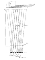
一般に、間隔の離れた部分瞳の光束を利用して焦点検出すると精度が良いことが知られている。したがって、図19のように隣接する2つのマイクロレンズ182,183と、それに対応する2つの光電変換素子アレイ184,185だけで構成すると検出精度が制約される。そこで、図22に示すように複数のマイクロレンズ187−1〜187−5に入射した光束を同数の光電変換素子アレイ188−1〜188−5で受光する。
In general, it is known that accuracy is good when focus detection is performed using light beams of partial pupils that are spaced apart from each other. Therefore, if only two
図22に示すように、焦点検出面181上の一点を通った光は、5つのマイクロレンズ187−1〜187−5に入射する。入射光の広がりは、点線で示した範囲になっているので、焦点検出面181上の一点を通った光は、図22に示した全てのマイクロレンズに入射することができる。これらマイクロレンズ187−1〜187−5に対応する複数の光電変換素子アレイ188−1〜188−5の信号出力を利用して像ずれ量を演算することができる。また、焦点検出を行うのであれば、これによりデフォーカス量を算出することができる。
As shown in FIG. 22, the light passing through one point on the
図19,図20の例では、部分瞳を5つとして説明したが、この5は最低限の例であり、好ましくは6以上であり、実用的には8以上とする。後述する図8は撮影レンズのF値が4の場合で、部分瞳は12個である。これをF値が8のものに変更すると、図9のように部分瞳は6個である。
尚、図を簡潔にするため、部分瞳の数を上述の値としているが、これに限るものではない。
In the example of FIGS. 19 and 20, the description has been made assuming that there are five partial pupils. However, this five is a minimum example, preferably 6 or more, and practically 8 or more. FIG. 8 to be described later shows a case where the F-number of the photographing lens is 4, and there are 12 partial pupils. If this is changed to an F value of 8, the number of partial pupils is 6, as shown in FIG.
In order to simplify the drawing, the number of partial pupils is set to the above-described value, but the present invention is not limited to this.
部分瞳の広がり(大きさ)が、F値相当でFPの光束が、マイクロレンズ下の受光部の配列ピッチに相当する広がりの範囲に入射(幾何光学的に)するとし、マイクロレンズの配列ピッチをP、マイクロレンズアレイと予定焦点面との距離をLとすると、焦点検出面におけるサンプリングピッチPdは、Pd=L/FPである。したがって、サンプリングピッチPdがマイクロレンズの配列ピッチPよりも小さく(P>Pd)なる条件は、P>L/FPである。すなわち、マイクロレンズアレイと予定焦点面との距離Lは、L<P×FPである。 Portion pupil spread (size) of the light flux F P in F value equivalent is incident on the range of expansion corresponding to the arrangement pitch of the light receiving portion of the lower microlenses (geometrical optics) Then, and arrangement of microlenses When the pitch P, and the distance between the microlens array and the predetermined focal plane is L, the sampling pitch Pd in the focus detection plane is Pd = L / F P. Accordingly, the sampling pitch Pd is smaller than the arrangement pitch P of the microlenses (P> Pd) following condition is P> L / F P. That is, the distance L between the microlens array and the planned focal plane is L <P × F P.
また、瞳の分割数をQ(≧5)とした時に、焦点検出面における受光部の像(逆投影像)が相関を取るのに十分な4つ以上重なるためには、(Q−4)×L/FP≧Pとなるため、上記距離Lは、L≧P×FP/(Q−4)となる。
[第1実施形態]
次に、図1、図2、図3、図4、図5、図6、図7、図8、図9、図10、図11、図23、図24、図25、図26、図27を参照して本発明の第1実施形態を説明する。本実施形態は、本発明の一実施の形態による結像状態検出装置(例えば焦点検出装置)を搭載した電子カメラシステムの実施形態である。先ず、電子カメラシステムの構成を説明する。
Further, when the number of pupil divisions is Q (≧ 5), in order for four or more images of the light receiving unit (back projection image) on the focus detection surface to overlap sufficiently to obtain a correlation, (Q-4) Since × L / F P ≧ P, the distance L is L ≧ P × F P / (Q-4).
[First Embodiment]
Next, FIGS. 1, 2, 3, 4, 5, 6, 7, 7, 8, 9, 10, 11, 23, 24, 25, 26, 27 The first embodiment of the present invention will be described with reference to FIG. The present embodiment is an embodiment of an electronic camera system equipped with an imaging state detection device (for example, a focus detection device) according to an embodiment of the present invention. First, the configuration of the electronic camera system will be described.
図1は、本実施形態の電子カメラシステムの構成図である。図1に示すように、電子カメラシステムは、カメラ本体200と、カメラ本体200に対し着脱可能な撮影レンズ100とを備えている。両者の接続箇所には、信号接続や駆動力伝達のためのカップリング部10が設けられている。
撮影レンズ100内には、被写体からの光束(被写体光束)を結像するレンズ群1、開口絞り2、駆動機構3などが備えられる。カメラ本体200内には、撮影レンズ100の光軸上に、クイックリターンミラー13が配置される。
FIG. 1 is a configuration diagram of the electronic camera system of the present embodiment. As shown in FIG. 1, the electronic camera system includes a
In the
カメラ本体200内において、クイックリターンミラー13の透過側には、シャッター11、撮像素子12が順に配置され、クイックリターンミラー13の反射側には、光学ファインダを構成するペンタプリズム6、接眼レンズ15が順に配置されている。
クイックリターンミラー13とシャッター11との間には、サブミラー14が配置され、そのサブミラー14の反射側に、焦点検出ユニット5が配置されている。なお、電子カメラシステムを銀塩フイルムを使用するカメラシステムにする場合は、撮像素子12の代わりにフイルムを配置すればよい。
In the
A sub mirror 14 is disposed between the
カメラ本体200には、各種の操作釦16が設けられている。換作者は、その操作釦16を介して電子カメラシステムに対し焦点調節の指示、撮影の指示、撮影レンズ100のF値の指定などをすることができる。
焦点調節の指示が入力されると、カメラ本体200内のマイクロプロセッサ9は、焦点検出ユニット5を駆動して焦点検出を行う。このとき、焦点検出ユニット5は、撮影レンズ100からの被写体光束の少なくとも1部に基づき、撮影レンズ100のデフオーカス量の情報を含む信号を取得し、マイクロプロセッサ9に送出する。焦点検出ユニット5の詳細は後述する。マイクロプロセッサ9は、その信号に基づきデフオーカス信号を生成し、そのデフオーカス信号を撮影レンズ100内の駆動機構3に与える。駆動機構3は、そのデフオーカス信号に基づいて、撮影レンズ100内の所定のレンズ群を変位させて焦点調節を行う。
When a focus adjustment instruction is input, the
撮影の指示が入力されると、マイクロプロセッサ9は、クイックリターンミラー13、シャッター11および開口絞り2を駆動し、撮影条件に見合った絞り値およびシャッタ速度により、撮影レンズ100からの被写体光束で撮像素子12を露光し、画像データを取得する。開口絞り2は駆動機構3を介して駆動される。
次に、焦点検出ユニット5の構成を詳しく説明する。
When a shooting instruction is input, the
Next, the configuration of the
図2は、焦点検出ユニット5及びその周辺の概略的な光路図である。図2において、符号14aはサブミラー14の反射面、符号12aは撮像素子12の撮像面であり、符号5aは反射面14aに関し撮像面12aと光学的に等価な予定焦点面である。この予定焦点面5aの近傍に、撮影レンズ100からの被写体光束が結像する。焦点検出ユニット5の焦点検出面は、この予定焦点面5aである。
FIG. 2 is a schematic optical path diagram of the
図2に示すように、焦点検出ユニット5には、予定焦点面5aから所定距離だけ離れた面にマイクロレンズアレイ52が配置され、さらにその後側にラインセンサアレイ53が配置され、マイクロレンズを通過した光が受光される。
像高の高い部分の光線を用いて焦点検出する場合に、光路中(予定焦点面5aの近傍からマイクロレンズの間)にフィールドレンズ51を挿入し、像高の高い部分の光線を光軸方向へ曲げるようにしてもよい。以下では、フィールドレンズ51を無視して説明する。
As shown in FIG. 2, in the
When focus detection is performed using a light beam having a high image height, a field lens 51 is inserted in the optical path (between the vicinity of the planned
図3は、焦点検出ユニット5の拡大図である。図3(A)は、焦点検出ユニット5を光軸を含む面で切断した概略断面図である。図3(B)は、マイクロレンズアレイ52とラインセンサアレイ53とを重ねて描いた場合の概略正面図である。
図3(A),(B)に示すように、マイクロレンズアレイ52には、複数の正のパワーを持つマイクロレンズ521−1〜521−12が、所定方向(図では左右方向)に所定ピッチで配置される。ラインセンサアレイ53は、マイクロレンズ521−1〜521−12のそれぞれに対応してラインセンサ531−1〜531−12を備えており、各ラインセンサ531−1〜531−12はそれぞれ同数の光電変換素子を有する。
FIG. 3 is an enlarged view of the
As shown in FIGS. 3A and 3B, in the
マイクロレンズアレイ52によるラインセンサ531−1〜531−12の逆投影像を図2に示す予定焦点面5a上に形成した場合、図4および図5で後述するように、少なくとも隣り合う一対のラインセンサの逆投影像は、少なくとも一部が互いに重複するように設計されている。個々のラインセンサ531内の光電変換素子531A,531B,・・・の並び方向は、マイクロレンズ521−1〜521−12及びラインセンサ531−1〜531−12の並び方向と同じ(図では左右方向)である。図3(A)、(B)においては、12個のラインセンサ531−1〜531−12を用いたが、連続した1本のラインセンサを用い、12個のマイクロレンズ521−1〜521−12に対応する12の範囲に存在する光電変換素子を使用してもよい。
When backprojected images of the line sensors 531-1 to 531-12 by the
図3(A)では、マイクロレンズアレイ52のマイクロレンズ521を平凸レンズのごとく表現したが、両凸レンズであってもよい。
この焦点検出ユニット5においては、互いに隣接するマイクロレンズ521の間のクロストーク(漏れ光の入射)を防ぐために、図3(A)に符号54で示したような遮光壁が設けられてもよい。
In FIG. 3A, the
In the
遮光壁54の代わりに絞りが設けられてもよい。この絞りの開口パターンは、複数の円をマイクロレンズ521と同じ配列パターンで並べたものである。この変形例のように、マイクロレンズアレイ52とラインセンサアレイ53との間に絞りを配置する代わりに、撮影レンズ100内や、クイックリターンミラー13の反射面、サブミラー14の反射面などに絞りを配置してもよい。以下では、遮光壁54や絞りを無視して説明する。
A diaphragm may be provided instead of the
図4は、焦点検出ユニット5内の個々のラインセンサ531と撮影レンズ100との関係を説明する図である。図4では、撮影レンズ100の概念を1枚のレンズで表し、撮影レンズ100から焦点検出ユニット5までの光路を、サブミラー14等を省略して直線的に表した。
図4に示すように、個々のラインセンサ531内の光電変換素子531A,531B,531D,・・・は、撮影レンズ100の瞳上の互いに異なる部分瞳A,B,C,D,・・・を個別に通過した光束を個別に受ける。これは、全てのラインセンサ531内の光電変換素子について当てはまる。
FIG. 4 is a diagram for explaining the relationship between the
As shown in FIG. 4,
そして、各ラインセンサ531は、対応する各マイクロレンズ521を介して、予定焦点面5a上の検出領域Eの輝度分布パターン、すなわち、図4の左右方向の輝度分布パターンを検出する。各ラインセンサ531による各検出領域Eは、概略マイクロレンズ521の配置ピッチに相当する距離ずつずれている。換言すると、少なくとも、隣り合う一対のラインセンサによる一対の検出領域は重複する。図5を参照してさらに検出領域Eを詳細に説明する。
Each
図5は、焦点検出ユニット5内の主要構成のサイズ及び位置関係を説明する図である。図5には、互いに隣接する2つの検出領域E−nおよびE−(n+1)を示した。これらの検出領域Eは、互いに隣接する2つのマイクロレンズ521−nおよび521−(n+1)のそれぞれに対応するラインセンサ531−nおよび531−(n+1)を、対応するマイクロレンズ521−nおよび521−(n+1)で予定焦点面5a上に個別に逆投影してできる逆投影像に対応する領域である。
FIG. 5 is a diagram for explaining the size and positional relationship of the main components in the
なお、図5では、説明の都合上、2つの検出領域Eを光軸方向にずらして描いた。検出領域E−n内の符号531A’,531B’,531C’,・・・は、ラインセンサ531−n内の光電変換素子531A,531B,531C,・・・を、対応するマイクロレンズ521−nで予定焦点面5a上に逆投影してできる逆投影像である。これらの逆投影像531A’ ,531B’,531C’,・・・のピッチPdは、ラインセンサ531による予定焦点面5a上のサンプルピッチに相当する。このように、予定焦点面5aから離れた位置にマイクロレンズアレイを配置し、マイクロレンズによって予定焦点面上に光電変換素子531A,531B,531C,・・・の逆投影像を形成するようにしたことにより、マイクロレンズ521−1〜521−12のピッチPよりも細かいピッチPdで焦点検出情報を抽出することができる。
In FIG. 5, for convenience of explanation, the two detection areas E are drawn shifted in the optical axis direction.
次に、マイクロレンズ521の光学的パワー、つまり予定焦点面5aとラインセンサ531との結像関係(共役関係)の詳細を説明する。
図6は、マイクロレンズ521による予定焦点面5aとラインセンサ531との結像関係(共役関係)を説明する図である。本焦点検出ユニット5では、図6(A)に示すように、予定焦点面5a上の1点がラインセンサ531上の1点にボケ無く結像される必要は無い。むしろ、図6(B)、(C)に示すように、若干のボケのある方が好ましい。以下、本焦点検出ユニット5に適したボケの程度について説明する。
Next, details of the optical power of the
FIG. 6 is a diagram for explaining the imaging relationship (conjugate relationship) between the planned
図7は、本焦点検出ユニット5に適したボケの程度を説明する図である。図7(A),(B)は、予定焦点面5a上に被写体の点像が形成されているときのラインセンサ531上の出力信号を示す図である。図7(A)にはボケが不足している場合を、図7(B)はボケの程度が適当である場合を示した。
図7(A)に示すように、ボケていないと、1つの光電変換素子でしか点像を検出しないので、点像の位置が僅か(1画素の幅寸法以下)にずれただけでは、光電変換素子の出力信号には変化が生じ無い。
FIG. 7 is a diagram for explaining the degree of blur suitable for the
As shown in FIG. 7A, since the point image is detected by only one photoelectric conversion element if it is not blurred, if the position of the point image is slightly shifted (below the width dimension of one pixel), No change occurs in the output signal of the conversion element.
一方、図7(B)に示すように、ボケの程度が複数画素に広がる程度だと、複数の光電変換素子で点像を検出するので、点像の位置が僅か(1画素の幅寸法以下)にずれただけでも、複数の光電変換素子の出力信号に変化が生じる。よって、ボケていない場合に比べ高精度な検出が可能である。
以上説明した理由により、本焦点検出ユニット5においては、個々のマイクロレンズ521、予定焦点面5a、及びラインセンサ531の関係は、このような適当なボケが生じるように、適当な量だけ共役関係からのずれが与えられる。
On the other hand, as shown in FIG. 7B, when the degree of blur spreads to a plurality of pixels, a point image is detected by a plurality of photoelectric conversion elements, and the position of the point image is slightly (less than the width dimension of one pixel). ), The output signals of the plurality of photoelectric conversion elements change. Therefore, highly accurate detection is possible as compared with the case where there is no blur.
For the reason described above, in the
但し、実際のボケは、マイクロレンズ521における回折、マイクロレンズ521の収差(球面収差)によっても生じるので、それらを総合したボケが適当なボケとなるように各部は設計される。
次に、上述した焦点検出ユニット5の具体例を説明する。
図8は、撮影レンズ100の検出につかえるF値(通常は開放F値)が「4」であるときの焦点検出ユニット5の具体例を示す図である。なお、図8では、複数のラインセンサ531及び複数の検出領域Eの互いに対応するもの同士に、互いに同じ識別番号i,(i+1),(i+2),(i+3),・・・を付した。
However, actual blur is also caused by diffraction in the
Next, a specific example of the
FIG. 8 is a diagram showing a specific example of the
この焦点検出ユニット5の各部の設計値は、以下のとおりである。
・マイクロレンズ521の径(有効径)A:50μm
・マイクロレンズ521の配置ピッチP:75μm
・予定焦点面5aからマイクロレンズアレイ52までの距離L:1200μm
・ラインセンサ531内の光電変換素子数Tn:12
・光電変換素子像の画素ピッチP d:25μm
図8では、互いに隣接する検出領域E−i,E−(i+1)のずれ量をPで表している。このずれ量は、マイクロレンズ521の配置ピッチに相当する長さである。焦点検出ユニット5では、長さP内に、逆投影像における光電変換素子の像が3個存在している。言い換えると、マイクロレンズ1ピッチあたりに1/3のピッチで(すなわち、3倍の分解能で)焦点検出信号が得られる。
Design values of each part of the
-
-
-Distance L from the planned
The number of photoelectric conversion elements in the
-Pixel pitch Pd of photoelectric conversion element image: 25 μm
In FIG. 8, the shift amount between the detection areas E-i and E- (i + 1) adjacent to each other is represented by P. This deviation amount is a length corresponding to the arrangement pitch of the
また、互いに隣接する検出領域E−i,E−(i+1)の重複幅D内に、光電変換素子像が9個存在している。したがって、互いに隣接するラインセンサ531−i,531−(i+1)を用いて、後述の第1のサンプリング方法による計算方法を用いる場合は、予定焦点面5a上で互いに重複する画素を最大9個まで用いてずれの計算を行うことができる。
In addition, nine photoelectric conversion element images exist within the overlapping width D of the detection areas E-i and E- (i + 1) adjacent to each other. Therefore, when the calculation method based on the first sampling method to be described later is used using the line sensors 531-i and 531-(i + 1) adjacent to each other, up to nine pixels overlapping each other on the planned
さらに、予定焦点面5a上では、最大で4つの検出領域E−i,E−(i+1),E−(i+2),E−(i+3)が重複する。つまり、予定焦点面5a上の1点に入射したF値=4の被写体光束は、4つのマイクロレンズ521に入射する。したがって、後述の第1のサンプリング方法を用いる場合は、図10で説明するように、F値=4の撮影レンズ100では、4つのマイクロレンズ521に対応する4つのラインセンサ531からの信号を用いて焦点検出演算を行うことができる。
Furthermore, on the planned
またさらに、後述の第2のサンプリング方法を用いる時は、4つ以上のマイクロレンズに対応するラインセンサの信号を用いて焦点検出演算を行うことができる。
次に、この焦点検出ユニット5を用いたカメラにおいて、撮影レンズ100のF値が「4」から「8」に変更された場合を説明する。
図9は、撮影レンズ100のF値が「8」であるときの焦点検出ユニット5の具体例を示す図である。
Furthermore, when a second sampling method described later is used, focus detection calculation can be performed using signals from line sensors corresponding to four or more microlenses.
Next, in the camera using the
FIG. 9 is a diagram illustrating a specific example of the
図9に示すように、撮影レンズ100のF値が「8」に設定されると、検出領域E内の光電変換素子像の数は6になる。すなわち、1つのラインセンサ531の12個の光電変換素子のうち中央部の6個の光電変換素子の出力信号を用いる。
このとき、互いに隣接する検出領域E−i,E−(i+1)の重複幅D内には、光電変換素子の逆投影像が3つ存在する。したがって、互いに隣接するラインセンサ531−i,531−(i+1)は、予定焦点面5a上で互いに3画素分の重複する領域を持つことができる。この場合、後述の第1のサンプリング方法を用いる計算では、相関を取れる画素が4画素に足りず、精度が十分でない場合もある。しかしながら、この場合でも、後述の第2のサンプリング方法を用いた計算を行えば、有効な焦点検出演算ができる。
As shown in FIG. 9, when the F value of the photographing
At this time, there are three back-projected images of the photoelectric conversion elements in the overlapping width D of the detection areas E-i and E- (i + 1) adjacent to each other. Therefore, the line sensors 531-i and 531-(i + 1) adjacent to each other can have an area of 3 pixels overlapping on the planned
次に、図8および図9で説明した焦点検出ユニット5から出力されるラインセンサの出力信号に基づいて、図1のマイクロプロセッサ9による像ずれの演算方法について説明する。撮影レンズ100のF値が「4」であるときと、F値が「8」であるときとでは、像ずれの演算手順(使用可能範囲)が異なるので、順に説明する。
図10は、撮影レンズ100のF値が「4」であるときのラインセンサ上の像のずれる様子を説明する図である。
Next, an image shift calculation method by the
FIG. 10 is a diagram for explaining how the image on the line sensor shifts when the F value of the photographing
撮影レンズ100により予定焦点面5a上に被写体の像Iが形成されると、互いに隣接する4つのラインセンサ531−i,531−(i+1),531−(i+2),531−(i+3)が、互いに同じ像Iの二次像I’を検出する。図10の下部に示すように、4つのラインセンサ531−i,531−(i+1),531−(i+2),531−(i+3)上の二次像は、4つのラインセンサの間で所定距離ずつ横方向にずれている。これら4つのラインセンサ531−i,531−(i+1),531−(i+2),531−(i+3)のうち、或る2つのラインセンサ531−i,531−jの間の二次像の横方向のずれ量は、それら2つのラインセンサ531−i,531−jの間隔が離れているほど、大きい。
When the image I of the subject is formed on the planned
一方、撮影レンズ100により図10の上部に矢印で示す方向の、予定焦点面5aからずれた面に被写体の像Iが形成されたときにも、互いに隣接する4つのラインセンサ531−i,531−(i+1),531−(i+2),531−(i+3)は、像Iの二次像を検出する。この場合は、像Iの二次像は、図10の下部に矢印で示すように、予定焦点面上に像Iが形成されているときと比較してそれぞれ横方向に、すなわち、素子の並び方向へずれる。その横ずれ量は、像Iのデフオーカス量に応じた量である。
On the other hand, even when the subject image I is formed on the surface deviated from the planned
このような状況において、デフオーカス量の演算手順は次のようになる。F値が「4」のときには、マイクロプロセッサ9は、互いに隣接する4つのラインセンサ531−i,531−(i+1),531−(i+2),531−(i+3)の出力信号の、いずれか一対のラインセンサに対応する出力信号に基づいて、後で図24で説明する演算手順を用いて像ずれ量を求め、続いてデフオーカス量を算出する。
In such a situation, the procedure for calculating the amount of differential is as follows. When the F value is “4”, the
たとえば、4つのラインセンサ531−i,531−(i+1),531−(i+2),531−(i+3)のうち、外側の2つのラインセンサ531−i,531−(i+3)の間では、二次像の横ずれ量が大きいので、それら2つのラインセンサ531−i,531−(i+3)の出力信号を利用すれば、マイクロプロセッサ9は、高精度にデフオーカス量を演算することができる。
For example, among the four line sensors 531-i, 531- (i + 1), 531- (i + 2), 531- (i + 3), between the two outer line sensors 531-i, 531- (i + 3), two Since the lateral shift amount of the next image is large, the
一方、デフオーカス量が大きいときには、二次像の横ずれ量が大き過ぎて外側の2つのラインセンサ531−i,531−(i+3)の出力信号から二次像の横ずれ量を検出できない場合がある。その場合には、互いに隣接する2つのラインセンサ531−i,531−(i+1)、もしくは531−(i+1),531−(i+2)、あるいは531−(i+3),531−(i+3)の出力信号を利用すれば、マイクロプロセッサ9は確実にデフオーカス量を演算することができる。
On the other hand, when the amount of the defocus is large, the lateral shift amount of the secondary image may be too large to detect the lateral shift amount of the secondary image from the output signals of the two outer line sensors 531-i and 531- (i + 3). In that case, the output signals of two line sensors 531-i, 531- (i + 1), 531- (i + 1), 531- (i + 2), or 531- (i + 3), 531- (i + 3) adjacent to each other. , The
なお、被写体の像によっては、特定の位置に配置された4つのラインセンサ531−i,531−(i+1),531−(i+2),531−(i+3)の出力信号から二次像の横ずれ量を検出できない場合もある。その場合には、配置箇所の異なる4つのラインセンサ531−j,531−(j+1),531−(j+2),531−(j+3)の出力信号を利用すれば、マイクロプロセッサ9は確実にデフオーカス量を演算することができる。
Depending on the image of the subject, the amount of lateral displacement of the secondary image from the output signals of the four line sensors 531-i, 531-(i + 1), 531-(i + 2), 531-(i + 3) arranged at a specific position. May not be detected. In that case, if the output signals of four line sensors 531-j, 531- (j + 1), 531- (j + 2), 531- (j + 3) having different arrangement locations are used, the
図11は、撮影レンズ100のF値が「8」であるときのデフオーカス量の計算手順を説明する図である。撮影レンズ100により予定焦点面5a上に被写体の像Iが形成されると、互いに隣接する2つのラインセンサ531−i,531−(i+1)が、互いに同じ像Iの二次像I’を検出することができる。
一方、撮影レンズ100により予定焦点面5aからずれた面に被写体の像Iが形成されたときにも、互いに隣接する2つのラインセンサ531−i,531−(i+1)は、像Iの二次像を検出することができる。その二次像は、図11の下部に矢印で示すように、予定焦点面上に像Iが形成されているときと比較してそれぞれ横方向に、すなわち、素子の並び方向へずれる。その横ずれ量は、デフォーカス量に応じた量である。
FIG. 11 is a diagram for explaining a calculation procedure of the amount of defocus when the F value of the photographing
On the other hand, even when the subject image I is formed on the surface deviated from the planned
この場合、マイクロプロセッサ9は、デフォーカス量の大小によらず、常に互いに隣接する2つのラインセンサ531−i,531−(i+1)の出力信号に基づいて、後で説明する図24による演算手順を用いて像ずれ量を求め、続いてデフオーカス量を計算する。
なお、被写体の像によっては、特定の位置に配置された2つのラインセンサ531−i,531−(i+1)の出力信号から二次像の横ずれを検出できない場合もある。その場合には、配置箇所の異なる2つのラインセンサ531−j,531−(j+1)の出力信号を利用すれば、マイクロプロセッサ9は確実にデフオーカス量を計算することができる。たとえば、図11の場合、2つのラインセンサ531−(i+1),531−(i+2)を用いてもよい。
In this case, the
Depending on the image of the subject, the lateral shift of the secondary image may not be detected from the output signals of the two line sensors 531-i and 531- (i + 1) arranged at specific positions. In that case, if the output signals of the two line sensors 531-j and 531- (j + 1) having different arrangement locations are used, the
上記の構成を有する焦点検出ユニット5における2種類の検出信号サンプリング方法について図23〜図26を参照して説明する。
―第1のサンプリング方法―
第1のサンプリング方法では、マイクロレンズ521のピッチPよりも細かいピッチにて第1信号列{a(i)}と第2信号列{b(i)}を抽出することが可能である。すなわち、図23に示すように、マイクロレンズ521−1に対応するラインセンサ531−1の複数の光電変換素子から第1信号列{a(i)}={a(1)、a(2)、・・・、a(8)、・・・}を形成し、マイクロレンズ521−2に対応するラインセンサ531−2の複数の光電変換素子から第2信号列{b(i)}={b(1)、b(2)、・・・、b(8)、・・・}を形成する。
Two types of detection signal sampling methods in the
―First sampling method―
In the first sampling method, it is possible to extract the first signal sequence {a (i)} and the second signal sequence {b (i)} at a pitch finer than the pitch P of the
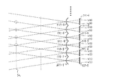
図23の焦点検出面5aにおけるラインセンサ531−1を構成する光電変換素子a1〜a8の逆投影像は、a1’〜a8 ’で示され、同様にラインセンサ531−2を構成する光電変換素子b1〜b8の逆投影像はb1’〜b8 ’で示される。そして、予定焦点面上では、a1’とb3’、a2’とb4’、a3’とb5’、a4’とb6’、・・・とがそれぞれ対応する。したがって、第1信号列{a(i)}および第2信号列{b(i)}において、a(1)とb(3)、a(2)とb(4)、a(3)とb(5)、a(4)とb(6)、・・・がそれぞれ対応する。すなわち、焦点検出面5a上の一点鎖線で示す微小領域5a12近傍の像が検出される。隣接する破線で示す微小領域5a23の像は、同様にしてラインセンサ531−2および531−3の出力信号を用いて検出される。像を検出するラインセンサ531のペアの選択方法は、隣接するラインセンサ531をペアとするものに限らず、予定焦点面5a上でラインセンサの逆投影像が重複するペアであれば良く、たとえば、ラインセンサ531−1と531−3を選択してもよい。いずれのラインセンサ531を選択するかにより、像ずれ量をデフオーカス量に換算する係数は異なる。
―第2のサンプリング方法―
第2のサンプリング方法では、第1信号列{a(i)}と第2信号列{b(i)}とを抽出するために、図25に示すように、マイクロレンズ521−1に対応するラインセンサ531−1の複数の光電変換素子の出力信号の中から信号a(1)を抽出し、以下マイクロレンズ521−2〜521−6のそれぞれに対して、信号a(1)に対応する信号a(2)〜a(6)を抽出して、第1信号列{a(i)}={a(1)、a(2)、・・・、a(6)}を形成する。同様にして、ラインセンサ531−1〜531−6の光電変換素子の出力信号の中で第1信号列{a(i)}として抽出されなかった出力信号から第2信号列{b(i)}={b(1)、b(2)、・・・、b(6)}を形成する。図25の焦点検出面5aにおける同一の像による信号出力を表す第1信号列{a(i)}および第2信号列{b(i)}の対応関係は、a(1)=b(3)、a(2)=b(4)、a(3)=b(5)、a(4)=b(6)、・・・である。
The back-projected images of the photoelectric conversion elements a1 to a8 constituting the line sensor 531-1 on the
-Second sampling method-
In the second sampling method, in order to extract the first signal sequence {a (i)} and the second signal sequence {b (i)}, as shown in FIG. 25, it corresponds to the microlens 521-1. The signal a (1) is extracted from the output signals of the plurality of photoelectric conversion elements of the line sensor 531-1 and corresponds to the signal a (1) for each of the microlenses 521-2 to 521-6 hereinafter. The signals a (2) to a (6) are extracted to form a first signal sequence {a (i)} = {a (1), a (2), ..., a (6)}. Similarly, the second signal sequence {b (i) from the output signal not extracted as the first signal sequence {a (i)} among the output signals of the photoelectric conversion elements of the line sensors 531-1 to 531-6. } = {B (1), b (2),..., B (6)}. The correspondence relationship between the first signal sequence {a (i)} and the second signal sequence {b (i)} representing the signal output by the same image on the
第1信号列{a(i)}と第2信号列{b(i)}は、たとえば、図26(a)〜(d)に示すようないずれかの組み合わせを選ぶことが可能である。明るいレンズの合焦近傍では、検出開角が大きくてデフオーカス検出精度を高くできる図26(a)のような信号列の選択が効率的である。また、デフオーカスの大きい場合は、大きなずれ量を捕捉できる図26(d)のように信号列を選択するのが効率的である。いずれの方式で信号列を選択するかにより検出開角は異なるので、像ずれ量をデフオーカス量に換算する係数は信号列の選び方、すなわち図26(a)〜(d)のいずれかを選択するかにより異なる。 For the first signal sequence {a (i)} and the second signal sequence {b (i)}, for example, any combination as shown in FIGS. 26A to 26D can be selected. In the vicinity of the in-focus state of a bright lens, it is efficient to select a signal sequence as shown in FIG. 26 (a) that can increase the detection aperture angle and increase the defocus detection accuracy. Further, when the differential focus is large, it is efficient to select a signal string as shown in FIG. Since the detection opening angle differs depending on which method is used to select the signal sequence, the coefficient for converting the image shift amount into the defocus amount selects one of the signal sequences, that is, any one of FIGS. 26 (a) to (d). It depends on what.
第1および第2のサンプリング方法により形成された第1信号列{a(i)}および第2信号列{b(i)}のずれ量を、以下で説明する公知の方法により算出する。
図25に示す第1信号列{a(i)}と第2信号列{b(i)}(i=1,2,・・・)の組み合わせから、一対の像(信号列)の相関量C(N)を以下の式(1)より求める。
The shift amount between the first signal sequence {a (i)} and the second signal sequence {b (i)} formed by the first and second sampling methods is calculated by a known method described below.
From the combination of the first signal sequence {a (i)} and the second signal sequence {b (i)} (i = 1, 2,...) Shown in FIG. 25, the correlation amount of a pair of images (signal sequences). C (N) is obtained from the following equation (1).

式(1)により離散的に算出された相関量C(N)を用いてシフト量Naを求める。シフト数Nのときに極小値を与える相関量をC0、シフト数(N−1)における相関量をCr、シフト数(N+1)における相関量をCfとして、シフト量Naは、以下の式(2)〜(4)により算出される。
DL=0.5×(Cr−Cf) ・・・(2)
E=MAX{Cf−C0、Cr−C0} ・・・(3)
Na=N+DL/E ・・・(4)
式(4)に焦点検出面の位置に応じた補正量Constを加えることにより、焦点検出面上での像ずれ量Δnを式(5)により算出する。
Δn=Na+Const ・・・(5)
この像ずれ量Δnを利用して、デフオーカス量Dfを式(6)を用いて算出できる。
Df=Kf×Δn ・・・(6)
なお、Kfは検出開角に依存した定数である。
The shift amount Na is obtained using the correlation amount C (N) discretely calculated by the equation (1). The shift amount Na giving the minimum value when the shift number is N is C0, the correlation amount at the shift number (N-1) is Cr, the correlation amount at the shift number (N + 1) is Cf, and the shift amount Na is expressed by the following equation (2 ) To (4).
DL = 0.5 × (Cr−Cf) (2)
E = MAX {Cf-C0, Cr-C0} (3)
Na = N + DL / E (4)
By adding the correction amount Const corresponding to the position of the focus detection surface to the equation (4), the image shift amount Δn on the focus detection surface is calculated by the equation (5).
Δn = Na + Const (5)
By using this image shift amount Δn, the defocus amount Df can be calculated using equation (6).
Df = Kf × Δn (6)
Kf is a constant depending on the detected opening angle.
さらに、KfはΔnに依存して変化する場合もあるので、実際には、実験的にKf(Δn)を決めるのが望ましい。
図27に示すフローチャートを用いて、焦点検出ユニット5による像ずれ検出動作を説明する。なお、このフローチャートに示す各処理は、マイクロプロセッサ9によりプログラムを実行して行われる。また、このフローチャートは操作釦16を操作することにより開始される。
Furthermore, since Kf may vary depending on Δn, it is actually desirable to experimentally determine Kf (Δn).
The image shift detection operation by the
ステップS1において、ラインセンサ53の電荷蓄積を開始して、所定の蓄積時間経過後にラインセンサ53の各素子から出力信号(画像データ)を取り込んでステップS2へ進む。
ステップS2においては、判定基準に応じて第1のサンプリング方法または第2のサンプリング方法を選択する。第1のサンプリング方法が選択された場合はステップS3へ進み、第2のサンプリング方法が選択された場合はステップS4へ進む。なお、判定基準は、たとえばデフオーカス量に基づく基準であり、デフオーカス量が所定値を越える場合は第2のサンプリング方法を選択し、デフオーカス量が所定値以内の場合は第1のサンプリング方法を選択するようにする。
In step S1, charge accumulation of the
In step S2, the first sampling method or the second sampling method is selected according to the determination criterion. If the first sampling method is selected, the process proceeds to step S3. If the second sampling method is selected, the process proceeds to step S4. Note that the determination criterion is, for example, a criterion based on the amount of defocus, and when the amount of defocus exceeds a predetermined value, the second sampling method is selected, and when the amount of defocus is within a predetermined value, the first sampling method is selected. Like that.
ステップS3においては、前述したように第1のサンプリング方法により第1信号列{a(i)}および第2信号列{b(i)}を抽出してステップS5へ進む。ステップS4においては、前述したように第2のサンプリング方法により第1信号列{a(i)}および第2信号列{b(i)}を抽出してステップS5へ進む。ステップS5では、前述したように第1信号列{a(i)}と第2信号列{b(i)}のずれ量を算出してステップS6へ進む。 In step S3, as described above, the first signal sequence {a (i)} and the second signal sequence {b (i)} are extracted by the first sampling method, and the process proceeds to step S5. In step S4, as described above, the first signal sequence {a (i)} and the second signal sequence {b (i)} are extracted by the second sampling method, and the process proceeds to step S5. In step S5, as described above, the shift amount between the first signal sequence {a (i)} and the second signal sequence {b (i)} is calculated, and the process proceeds to step S6.
ステップS6において、式(6)を用いてデフオーカス量を算出してステップS7へ進む。ステップS7においては、ステップS6で算出されたデフオーカス量を駆動機構3に出力し、撮影レンズ100内の所定のレンズ群を駆動させて、ステップS1へ戻る。
なお、以上の処理手順は、撮影レンズ100のF値に応じて選択された複数のラインセンサ531から出力される信号に対して実行される。
In step S6, the defocus amount is calculated using equation (6), and the process proceeds to step S7. In step S7, the defocus amount calculated in step S6 is output to the
The above processing procedure is executed for signals output from the plurality of
以上、本実施形態の焦点検出ユニット5によれば次の作用効果を奏する。
(1)マイクロプロセッサ9は、撮影レンズ100が明るい(F値が小さい)ときほど高精度に焦点検出をすることができる。
(2)本実施形態の焦点検出ユニット5は、予定焦点面5a上の互いにずれた検出領域Eを、多数のマイクロレンズ521及びラインセンサ531が分担して検出するので、仮に、従来の瞳分割再結像方式(特許文献1など)の逆投影像における素子のピッチPdを同じに設定したとしても、予定焦点面5aからマイクロレンズ521までの距離Lを、従来の瞳分割再結像方式(特許文献1など)のそれよりも短縮することができる。つまり、本実施形態の焦点検出ユニット5は、高精度でありながら小型化が容易である。
(3)本実施形態の焦点検出ユニット5においては、マイクロレンズアレイ52の形成された光学部材とラインセンサアレイ53とが近接するので、両者の位置合わせが容易かつ高精度であり、その結果、誤差によるバラツキが減って、焦点検出精度が高精度であるという利点もある。
(4)本実施形態の焦点検出ユニット5には、複数のラインセンサ531をライン方向に配列してなるラインセンサアレイ53が用いられたが、ラインセンサアレイ53の代わりに、それら複数のラインセンサ531を連結してできる1本のラインセンサが用いられてもよい。
As described above, according to the
(1) The
(2) The
(3) In the
(4) The
[第1実施形態の変形例]
なお、本実施形態の焦点検出ユニット5を次のように変形することができる。
(1)上述した焦点検出ユニット5を利用して、撮影レンズ100の絞り込み像面移動量を、電子カメラシステムが自己検出することも可能になる。すなわち、マイクロプロセッサ9は、焦点検出ユニット5の互いに隣接する4つのラインセンサ531−i,531−(i+1),531−(i+2),531−(i+3)のうち、外側の2つのラインセンサ531−i,531−(i+3)を利用して認識したデフオーカス量と、中央部で隣接する2つのラインセンサ531−(i+1),531−(i+2)を利用して認識したデフオーカス量との差異を求める。この差異によって、マイクロプロセッサ9は、撮影レンズ100の絞り込み像面移動量を認識することができる。絞り込み像面移動量とは、F値を「4」から「8」へと変化させたときの撮影レンズ100の焦点面のずれ量である。その情報を利用すれば、マイクロプロセッサ9は、より高精度な焦点調節を行うことができる。
(2)本実施形態のマイクロプロセッサ9は、撮影レンズ100に設定中のF値に応じて出力信号の参照元となるラインセンサ531を変更したが、撮影レンズ100に設定予定のF値(露光時の制御F値)に応じて出力信号の参照元となるラインセンサ531を変更してもよい。
(3)本実施形態のマイクロプロセッサ9は、撮影レンズ100に設定中のF値、及び/又は撮影レンズ100に設定予定のF値に応じて、デフオーカス信号を生成するための演算の内容を変更してもよい。
(4)第1実施形態の焦点検出ユニット5においては、焦点検出の精度を向上させるために、マイクロレンズアレイ52及びラインセンサアレイ53からなる光学系を、2方向に亘って配列することが望ましい。つまり、第1方向に配列されたラインセンサアレイを持つマイクロレンズアレイと、第2方向に配列されたラインセンサアレイを持つマイクロレンズアレイとを備えてもよい。
[Modification of First Embodiment]
Note that the
(1) Using the
(2) Although the
(3) The
(4) In the
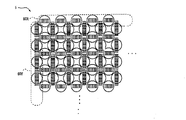
図12は、焦点検出ユニット5の変形例の正面図である。この焦点検出ユニット5においては、横方向にマイクロレンズアレイ52及びラインセンサアレイ53を並べた第1の光学系60Xと、縦方向にマイクロレンズアレイ52及びラインセンサアレイ53を並べた第2の光学系60Yとを、複数個ずつ密に並べてなる。
すなわち、図12の焦点検出ユニット5は、第1方向に配列された複数の光電変換素子(受光部)で構成される受光部群601、および、ひとつの受光部群601に光束を導くマイクロレンズ602で構成される第1検出光学系60Xを複数備える。また、第2方向に配列された複数の光電変換素子で構成される受光部群611、および、ひとつの受光部群611に光束を導くマイクロレンズ612で構成される第2検出光学系60Yを複数備える。そして、これら複数の第1および第2検出光学系60X,60Yを互い違いの市松状に配置して構成される。
FIG. 12 is a front view of a modified example of the
That is, the
このように、第1の光学系60Xと第2の光学系60Yとの双方が配置されれば、予定焦点面5a上の各位置のパターンを、縦横の2方向について検出(所謂「十字検出」)することが可能になる。
また、第1の光学系60X及び第2の光学系60Yが複数個ずつ密に配置されれば、予定焦点面5a上の検出領域の配置密度は高まり、被写体のいろいろな部分で焦点検出が可能となる。
As described above, when both the first
Further, if a plurality of the first
特に、複数の第1の光学系60Xと複数の第2の光学系60Yとが互い違いに(市松状に)配置されれば、前述した十字検出を、予定焦点面5a上の各位置について行うことが可能になる。高い面密度で検出が可能なことで、被写体が少し動いても、焦点検出のとび対策が可能なので、安定した焦点検出が可能となる。
(5)図12に示す配列を、図13に示すように変形することもできる。図13に示す焦点検出ユニット5においては、第1方向のラインセンサアレイ53よりも第2方向のラインセンサアレイ53の長さが長くなるように設けられている。二方向に配列されたラインセンサ53において、双方のラインセンサ53が干渉しないように一方向の長さを長くすることにより、F値の小さい明るいレンズに対する検出能力を増大させることができる。
(6)さらに、図12に示す配列を、図14に示すように変形することもできる。図14に示す焦点検出ユニット5においては、第1方向の配列ピッチP1と第2方向の配列ピッチP2とが異なるように設けられている。この場合、マイクロレンズの配列ピッチP1が小さく、密に並んだ方向の検出精度の向上が期待できる。
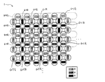
(7)上述した実施形態では、焦点検出ユニット5の分光感度については特に言及しなかったが、焦点検出ユニット5に分光感度特性を付与してもよい。図15は、分光感度特性を持つ焦点検出ユニット5の正面図である。図15においては、R(赤),G(緑),B(青)の3色の各々に感度を持つ3種類の光学系60XR,60XG,60XBが複数個ずつX方向に並べられるとともに、R(赤),G(緑),B(青)の3色の各々に感度を持つ3種類の光学系60YR,60YG,60YBが複数個ずつX方向に並べられている。
In particular, if the plurality of first
(5) The arrangement shown in FIG. 12 can be modified as shown in FIG. In the
(6) Furthermore, the arrangement shown in FIG. 12 can be modified as shown in FIG. In the
(7) Although the spectral sensitivity of the
すなわち、図15の焦点検出ユニット5においては、複数の第1検出光学系60XG、60XB、60XRは、異なる分光感度特性を有する受光部群601G、601B、601Rを含み、複数の第2検出光学系60YG、60YB、60YRも、異なる分光感度特性を有する受光部群611G、611B、611Rを含む。
なお、図では、光学系60XB、60YB内のラインセンサが黒く塗りつぶされているが、実際には、このラインセンサにも複数の光電変換素子が配列されている。
That is, in the
In the figure, the line sensors in the optical systems 60XB and 60YB are painted black, but actually, a plurality of photoelectric conversion elements are also arranged in this line sensor.
これらの3種類の光学系60XR,60XG,60XBと60YR,60YG,60YBを配列する場合、G色に感度を持つ光学系60XGと60YGの配置密度を、他の2種類の光学系60XRおよび60YRと、60XBおよび60XBのそれよりも高くすると、焦点検出ユニット5の全体の分光感度特性を、G色に敏感な人間の眼の分光感度特性に近づけることができるので、好ましい。
When these three types of optical systems 60XR, 60XG, 60XB and 60YR, 60YG, 60YB are arranged, the arrangement density of the optical systems 60XG and 60YG having sensitivity to the G color is set to the other two types of optical systems 60XR and 60YR. , 60XB and higher than that of 60XB are preferable because the overall spectral sensitivity characteristics of the
また、通常主に検出に用いるG色の配列の密度が高いので、効果的である。
(8)図15においては、可視光の3色に感度を持つ3種類の光学系60XR,60XG,60XBと60YR,60YG,60YBが配列されているが、可視光に感度を持つ光学系と、可視光及び赤外光に感度を持つ光学系との2種類を用意し、それらを配列してもよい。
Further, since the density of the G color array which is usually used mainly for detection is high, it is effective.
(8) In FIG. 15, three types of optical systems 60XR, 60XG, 60XB and 60YR, 60YG, 60YB having sensitivity to three colors of visible light are arranged, but an optical system having sensitivity to visible light, Two types of optical systems having sensitivity to visible light and infrared light may be prepared and arranged.
何れの場合も、互いに異なる複数種類の分光感度でデフオーカス量を検出することができるので、撮影レンズ100の色収差の大きさの検出、ひいては色収差の補正が可能となり、焦点検出精度のさらなる向上を図ることができる。
(9)図15に示した焦点検出ユニット5の光学系60XR,60XG,60XBと60YR,60YG,60YBは、それぞれ1種類の色(波長)しか検出しないが、図16又は図17に示すように、1種類の光学系が2種類以上の色(波長)を検出できるように構成されてもよい。
In either case, the defocus amount can be detected with a plurality of different types of spectral sensitivities, so that it is possible to detect the magnitude of chromatic aberration of the photographing
(9) The optical systems 60XR, 60XG, 60XB and 60YR, 60YG, 60YB of the
図16には、1つの検出列に対して2種類の色を検出可能な光学系を利用した焦点検出ユニット5を示した。図16において符号60XGRと60YGRで示すのは、G色及びR色を検出する光学系である。また、符号60XGBと60YGBで示すのは、G色及びB色を検出する光学系である。光学系60XGRと60YGRにおいては、G色に感度を有するラインセンサとR色に感度を有するラインセンサとが同一のマイクロレンズの後側に並列配置されており、光学系60XGBと60YGBにおいては、G色に感度を有するラインセンサとB色に感度を有するラインセンサとが同一のマイクロレンズの後側に並列配置されている。いずれの場合も、G色感度のラインセンサを持つようにして、多色化による検出密度の低下を防いでいる。
FIG. 16 shows the
図17には、1つの検出列に対して3種類の色を検出可能な光学系を利用した焦点検出ユニット5を示した。図17において符号60XRGBと60YRGBで示すのは、R色及びG色及びB色を検出する光学系である。光学系60XRGB、60YRGBにおいては、G色に感度を有するラインセンサ621G、631Gと、R色に感度を有するラインセンサ621R、631Rと、B色に感度を有するラインセンサ621B、631Bとが、同一のマイクロレンズの後側に並列配置されている。
FIG. 17 shows the
また、主要な検出アレイであるG色アレイの幅を広くするとともに、補助的に用いるR,B色アレイの幅を狭くして、通常の検出能力を保ちながら、多色化による性能劣化を防いでいる。
尚、G色としては、通常のイメージセンサのG感度分布より広く取る。例えば、視感度分布程度あるいはそれよりもさらに広い程度に取ると、光量の点で有利となり、好ましい。
(10)以上の焦点検出ユニット5においては、横方向にマイクロレンズアレイ52及びラインセンサアレイ53を並べた第1の光学系と、縦方向にマイクロレンズアレイ52及びラインセンサアレイ53を並べた第2の光学系とが交互に配置されたが、必ずしも交互でなくてよい。
(11)図18には、第1の光学系を密に配列したブロック70Xと、第2の光学系を密に配列したブロック70Yとを、ブロック交互に配置してなる焦点検出ユニット5を示した。
(12)上記説明ではマイクロレンズ毎に光電変換素子アレイを設けたが、1列に並ぶこれらの複数の光電変換素子アレイをまとめて、1本の光電変換素子アレイとしてもよいし、複数の光電変換素子アレイを2次元撮像素子で実現するように構成してもよい。又、図12〜図18の二次元配置は、これを面内に任意角度、例えば45°回転した配置にしてもよい。
(13)上述した実施形態では、結像状態検出装置(焦点検出装置)を搭載した電子カメラシステムを説明したが、本発明の実施形態による結像状態検出装置は、結像光学系を有した他の光学機器、例えばフィールドスコープなどの各種結像光学装置にも同様に搭載可能である。
(14)本発明の実施の形態による結像状態検出装置は、光学系の収差測定に適用することもできる。本発明の実施の形態による結像状態検出装置で被検光学系の瞳部分に依存したデフォーカス量や各像高におけるデフォーカス量をそれぞれ測定すれば、結果的にその被検光学系の収差が求まるからである。本発明の実施の形態による結像状態検出装置を適用した収差測定装置には、例えば、被検光学系を支持する機構と、被検光学系に対し物体側から測定光を投光する照明光学系と、被検光学系の像側に配置された本発明の実施の形態による結像状態検出装置と、結像状態検出装置の出力から被検光学系の収差を算出する演算装置とが備えられる。
In addition to widening the width of the G color array, which is the main detection array, and narrowing the width of the auxiliary R and B color arrays, maintaining the normal detection capability and preventing performance degradation due to multiple colors. It is out.
The G color is set wider than the G sensitivity distribution of a normal image sensor. For example, taking a luminous intensity distribution level or wider than that is advantageous in terms of light quantity, which is preferable.
(10) In the
(11) FIG. 18 shows the
(12) In the above description, a photoelectric conversion element array is provided for each microlens. However, a plurality of photoelectric conversion element arrays arranged in a row may be combined into one photoelectric conversion element array, or a plurality of photoelectric conversion elements may be combined. You may comprise so that a conversion element array may be implement | achieved by a two-dimensional image sensor. Further, the two-dimensional arrangements shown in FIGS. 12 to 18 may be arranged such that they are rotated at an arbitrary angle, for example, 45 ° in the plane.
(13) In the embodiment described above, the electronic camera system equipped with the imaging state detection device (focus detection device) has been described. However, the imaging state detection device according to the embodiment of the present invention has an imaging optical system. It can be similarly mounted on other optical devices, for example, various imaging optical devices such as a field scope.
(14) The imaging state detection device according to the embodiment of the present invention can also be applied to aberration measurement of an optical system. If the defocus amount depending on the pupil portion of the test optical system and the defocus amount at each image height are measured by the imaging state detection device according to the embodiment of the present invention, the aberration of the test optical system is consequently obtained. This is because The aberration measuring device to which the imaging state detecting device according to the embodiment of the present invention is applied includes, for example, a mechanism for supporting a test optical system and illumination optics for projecting measurement light from the object side to the test optical system. System, an imaging state detection device according to an embodiment of the present invention disposed on the image side of the test optical system, and an arithmetic unit that calculates the aberration of the test optical system from the output of the imaging state detection device It is done.
上記では、種々の実施の形態および変形例を説明したが、本発明はこれらの内容に限定されるものではない。本発明の技術的思想の範囲内で考えられるその他の態様も本発明の範囲内に含まれる。 Although various embodiments and modifications have been described above, the present invention is not limited to these contents. Other embodiments conceivable within the scope of the technical idea of the present invention are also included in the scope of the present invention.
Claims (15)
前記マイクロレンズアレイを構成する複数のマイクロレンズの後側へ個別に設けられた複数の受光部アレイと、
或るマイクロレンズに設けられた受光部アレイの光電変換出力から第1信号列{a(i);i=1,2,3,4,・・・}を作成すると共に、別のマイクロレンズに設けられた受光部アレイの光電変換出力から第2信号列{b(i);i=1,2,3,4,・・・}を作成する第1作成手段と、
i番目のマイクロレンズに設けられた受光部アレイのうち所定位置に配置された2つの受光部の光電変換出力から信号a(i),b(i)を抽出する処理を、複数のマイクロレンズについてそれぞれ行い、第1信号列{a(i);i=1,2,3,4,・・・}及び第2信号列{b(i);i=1,2,3,4,・・・}を作成する第2作成手段と、
前記第1作成手段が作成する1対の信号列と、前記第2作成手段が作成する1対の信号列とのうち一方を所定の判断基準で選択し、選択された1対の信号列が表す1対のパターンの間のズレ量により、前記結像光学系の前記予定焦点面における結像状態を検出する結像状態演算手段と
を備えることを特徴とする結像状態検出装置。 A microlens array having a plurality of microlenses arranged at a predetermined pitch on a plane deviated from a predetermined focal plane of the imaging optical system;
A plurality of light receiving section arrays individually provided on the rear side of the plurality of microlenses constituting the microlens array ;
A first signal sequence {a (i); i = 1, 2, 3, 4,...} Is created from the photoelectric conversion output of the light receiving unit array provided in a certain microlens, and another microlens is formed. First creating means for creating a second signal sequence {b (i); i = 1, 2, 3, 4,...} From the photoelectric conversion output of the provided light receiving section array;
A process of extracting signals a (i) and b (i) from photoelectric conversion outputs of two light receiving units arranged at predetermined positions in the light receiving unit array provided in the i-th micro lens is performed for a plurality of micro lenses. The first signal sequence {a (i); i = 1, 2, 3, 4,...} And the second signal sequence {b (i); i = 1, 2, 3, 4,. A second creation means for creating
One of the pair of signal sequences created by the first creation unit and the pair of signal sequences created by the second creation unit is selected based on a predetermined criterion, and the selected pair of signal sequences is An imaging state detection device comprising: an imaging state calculation means for detecting an imaging state on the predetermined focal plane of the imaging optical system based on a deviation amount between a pair of patterns to be expressed .
前記受光部アレイを前記予定焦点面上に逆投影した場合に形成される受光部像の配列ピッチPdは、前記マイクロレンズの配列ピッチPよりも小さい。 In the imaging state detection device according to claim 1,
The arrangement pitch Pd of the light-receiving section images formed when the light-receiving section array is back-projected onto the planned focal plane is smaller than the arrangement pitch P of the microlenses.
前記マイクロレンズの配列ピッチをP、前記結像光学系の部分瞳から1つの受光部へ入射する光束のF値をFP 、前記結像光学系の瞳の分割数をQとしたとき、前記マイクロレンズアレイの配置面から前記予定焦点面までの距離Lは、次式を満たす。
P×FP > L ≧ P×FP/(Q−4) In the imaging state detection device according to claim 1 or 2 ,
Wherein P the pitch of the microlenses, F value F P of the light beam incident from said imaging optical system portion pupil to one of the light receiving unit, when the division number of the pupil of the imaging optical system and is Q, the A distance L from the arrangement plane of the microlens array to the planned focal plane satisfies the following expression.
P × F P > L ≧ P × F P / (Q-4)
前記複数の受光部アレイの中には、受光部の配列方向が第1方向である複数の第1受光部アレイと、受光部の配列方向が前記第1方向とは異なる第2方向である複数の第2受光部アレイとが存在する。 In the imaging state detection apparatus according to any one of claims 1 to 3 ,
Multiple wherein the the plurality of light receiving portions array, a second direction different from the plurality of first light receiving unit array arrangement direction of the light receiving portion is the first direction, the arrangement direction of the light receiving portion is the first direction And a second light receiving section array .
前記複数の第1受光部アレイを個別に設けた複数のマイクロレンズと、前記複数の第2受光部アレイを個別に設けた複数のマイクロレンズとは、市松模様に配置される。 The imaging state detection device according to claim 4 ,
The plurality of microlenses provided with the plurality of first light receiving unit arrays and the plurality of microlenses provided with the plurality of second light receiving unit arrays are arranged in a checkered pattern.
前記複数の第1受光部アレイと前記複数の第2受光部アレイとは、市松模様に配置される。 The imaging state detection device according to claim 4 ,
The plurality of first light receiving unit arrays and the plurality of second light receiving unit arrays are arranged in a checkered pattern.
前記第1受光部アレイを設けたマイクロレンズの配列ピッチと、前記第2受光部アレイを設けたマイクロレンズの配列ピッチとは、互いに異なる。 The imaging state detection device according to claim 4 ,
The arrangement pitch of the microlenses provided with the first light receiving section array is different from the arrangement pitch of the microlenses provided with the second light receiving section array .
前記第1受光部アレイのアレイ方向の長さと、前記第2受光部アレイのアレイ方向の長さとは、互いに異なる。 The imaging state detection device according to claim 4 ,
Wherein the length of the array direction of the first light receiving portion array, the length of the array direction of the second light receiving section arrays are different from each other.
前記複数の受光部アレイの中には、互いに異なる分光感度特性を有した複数種類の受光部が存在する。 In the imaging state detection device according to any one of claims 1 to 8 ,
Wherein the the plurality of light receiving portions array, there are a plurality kinds of light-receiving portion which have a different spectral sensitivity characteristics.
前記複数の第1受光部アレイの中には、互いに異なる分光感度特性を有した複数種類の第1受光部アレイが存在する。 The imaging state detection device according to claim 4 ,
Wherein the the plurality of first light receiving section arrays, there are a plurality kinds of the first light receiving portion array have a different spectral sensitivity characteristics.
前記複数種類の受光部のうち、特定の分光感度特性を有した特定種類の受光部は、他の分光感度特性を有した他種類の受光部よりも高密度に配列される。 The imaging state detection device according to claim 9 ,
Among the plurality of types of light-receiving portion, the light receiving portion of the particular type that have a specific spectral sensitivity characteristics are densely arranged than other types of light receiving portions have a another spectral sensitivity characteristics.
前記複数の第1受光部アレイ及び前記複数の第2受光部アレイの各々の中には、特定の波長に感度を有した受光部が存在する。 In the imaging state detection device according to claim 10 ,
In each of the plurality of first light receiving portion array and the plurality of second light receiving section arrays, there is the light receiving section have a sensitivity to a specific wavelength.
互いに異なる分光感度特性を有した複数種類の受光部の間では、互いの大きさが異なる。 In the imaging state detection device according to claim 11 or 12 ,
Among a plurality of types of light-receiving portions having different spectral sensitivity characteristics from each other, they have different sizes each other.
Priority Applications (1)
| Application Number | Priority Date | Filing Date | Title |
|---|---|---|---|
| JP2006150686A JP4788481B2 (en) | 2005-05-30 | 2006-05-30 | Imaging state detection device, camera, and light receiving unit |
Applications Claiming Priority (3)
| Application Number | Priority Date | Filing Date | Title |
|---|---|---|---|
| JP2005157314 | 2005-05-30 | ||
| JP2005157314 | 2005-05-30 | ||
| JP2006150686A JP4788481B2 (en) | 2005-05-30 | 2006-05-30 | Imaging state detection device, camera, and light receiving unit |
Publications (3)
| Publication Number | Publication Date |
|---|---|
| JP2007011314A JP2007011314A (en) | 2007-01-18 |
| JP2007011314A5 JP2007011314A5 (en) | 2009-06-04 |
| JP4788481B2 true JP4788481B2 (en) | 2011-10-05 |
Family
ID=37749837
Family Applications (1)
| Application Number | Title | Priority Date | Filing Date |
|---|---|---|---|
| JP2006150686A Expired - Fee Related JP4788481B2 (en) | 2005-05-30 | 2006-05-30 | Imaging state detection device, camera, and light receiving unit |
Country Status (1)
| Country | Link |
|---|---|
| JP (1) | JP4788481B2 (en) |
Families Citing this family (19)
| Publication number | Priority date | Publication date | Assignee | Title |
|---|---|---|---|---|
| WO2006129677A1 (en) | 2005-05-30 | 2006-12-07 | Nikon Corporation | Image formation state detection device |
| JP5034556B2 (en) | 2007-02-27 | 2012-09-26 | 株式会社ニコン | Focus detection apparatus and imaging apparatus |
| JP4821674B2 (en) * | 2007-03-28 | 2011-11-24 | 株式会社ニコン | Focus detection apparatus and imaging apparatus |
| JP4973273B2 (en) * | 2007-03-28 | 2012-07-11 | 株式会社ニコン | Digital camera |
| JP5191168B2 (en) * | 2007-06-11 | 2013-04-24 | 株式会社ニコン | Focus detection apparatus and imaging apparatus |
| EP2028843B1 (en) | 2007-08-21 | 2013-10-23 | Ricoh Company, Ltd. | Focusing device and imaging apparatus using the same |
| JP4995002B2 (en) * | 2007-08-21 | 2012-08-08 | 株式会社リコー | Imaging device, focusing device, imaging method, and focusing method |
| WO2009044776A1 (en) | 2007-10-02 | 2009-04-09 | Nikon Corporation | Light receiving device, focal point detecting device and imaging device |
| JP5061858B2 (en) | 2007-11-12 | 2012-10-31 | 株式会社ニコン | Focus detection apparatus and imaging apparatus |
| JP5380857B2 (en) * | 2008-02-21 | 2014-01-08 | 株式会社ニコン | Focus detection apparatus and imaging apparatus |
| JP5130178B2 (en) * | 2008-03-17 | 2013-01-30 | 株式会社リコー | Focal length detection apparatus, imaging apparatus, imaging method, and camera |
| JP2010008873A (en) | 2008-06-30 | 2010-01-14 | Nikon Corp | Focus detecting device and imaging device |
| JP5272565B2 (en) * | 2008-08-05 | 2013-08-28 | 株式会社ニコン | Focus detection apparatus and imaging apparatus |
| JP5617157B2 (en) | 2008-08-20 | 2014-11-05 | 株式会社ニコン | Focus detection apparatus and imaging apparatus |
| EP2642260A4 (en) * | 2010-11-16 | 2015-12-09 | Nikon Corp | Multiband camera, and multiband image capturing method |
| JP5240591B2 (en) * | 2011-06-27 | 2013-07-17 | 株式会社リコー | Imaging device, focusing device, imaging method, and focusing method |
| JP5942697B2 (en) * | 2012-08-21 | 2016-06-29 | 株式会社ニコン | Focus detection apparatus and imaging apparatus |
| JP6476547B2 (en) * | 2014-01-28 | 2019-03-06 | 株式会社ニコン | Focus detection device and imaging device |
| JP2014149535A (en) * | 2014-03-03 | 2014-08-21 | Nikon Corp | Method and device for adjusting optical system |
-
2006
- 2006-05-30 JP JP2006150686A patent/JP4788481B2/en not_active Expired - Fee Related
Also Published As
| Publication number | Publication date |
|---|---|
| JP2007011314A (en) | 2007-01-18 |
Similar Documents
| Publication | Publication Date | Title |
|---|---|---|
| JP4788481B2 (en) | Imaging state detection device, camera, and light receiving unit | |
| WO2006129677A1 (en) | Image formation state detection device | |
| US7767946B2 (en) | Focus detection device and image pick-up device | |
| JP6202927B2 (en) | Distance detection device, imaging device, program, recording medium, and distance detection method | |
| JP5161702B2 (en) | Imaging apparatus, imaging system, and focus detection method | |
| EP2651118B1 (en) | Light receiving device, focus detection device and imaging device | |
| US20080205871A1 (en) | Focus detection device for image forming optical system, imaging apparatus, and focus detection method for image forming optical system | |
| JP5157128B2 (en) | Focus detection apparatus and imaging apparatus | |
| WO2010021195A1 (en) | Focal point detecting device | |
| JP4054422B2 (en) | Camera and interchangeable lens device | |
| JP2009198771A (en) | Focus detector and imaging device | |
| JP4802864B2 (en) | Focus detection apparatus and imaging apparatus | |
| JP2009151154A (en) | Photodetector, focus detector and imaging apparatus | |
| JP4208536B2 (en) | Focus detection device, imaging device having the same, and photographing lens | |
| JP2009294301A (en) | Light receiving device and focus detector | |
| JP2009128438A (en) | Focus detecting device for camera | |
| JP5493640B2 (en) | Focus detection device and imaging device | |
| JP2000258683A (en) | Focus detector and range-finding device | |
| JP4566804B2 (en) | Display device in viewfinder and camera having the same | |
| JP2009192882A (en) | Focus detection device and imaging apparatus | |
| JP4289707B2 (en) | Focus detection device | |
| JP4514202B2 (en) | Interchangeable lens, camera body and camera system | |
| JP2011043670A (en) | Focus detecting device and image pickup apparatus | |
| JP2006065070A (en) | Device and method for focus detection | |
| JP6153424B2 (en) | FOCUS DETECTION DEVICE, IMAGING DEVICE, FOCUS DETECTION METHOD, PROGRAM |
Legal Events
| Date | Code | Title | Description |
|---|---|---|---|
| A621 | Written request for application examination |
Free format text: JAPANESE INTERMEDIATE CODE: A621 Effective date: 20090319 |
|
| A521 | Written amendment |
Free format text: JAPANESE INTERMEDIATE CODE: A523 Effective date: 20090417 |
|
| A977 | Report on retrieval |
Free format text: JAPANESE INTERMEDIATE CODE: A971007 Effective date: 20110314 |
|
| TRDD | Decision of grant or rejection written | ||
| A01 | Written decision to grant a patent or to grant a registration (utility model) |
Free format text: JAPANESE INTERMEDIATE CODE: A01 Effective date: 20110621 |
|
| A01 | Written decision to grant a patent or to grant a registration (utility model) |
Free format text: JAPANESE INTERMEDIATE CODE: A01 |
|
| A61 | First payment of annual fees (during grant procedure) |
Free format text: JAPANESE INTERMEDIATE CODE: A61 Effective date: 20110704 |
|
| FPAY | Renewal fee payment (event date is renewal date of database) |
Free format text: PAYMENT UNTIL: 20140729 Year of fee payment: 3 |
|
| R150 | Certificate of patent or registration of utility model |
Ref document number: 4788481 Country of ref document: JP Free format text: JAPANESE INTERMEDIATE CODE: R150 Free format text: JAPANESE INTERMEDIATE CODE: R150 |
|
| FPAY | Renewal fee payment (event date is renewal date of database) |
Free format text: PAYMENT UNTIL: 20140729 Year of fee payment: 3 |
|
| R250 | Receipt of annual fees |
Free format text: JAPANESE INTERMEDIATE CODE: R250 |
|
| R250 | Receipt of annual fees |
Free format text: JAPANESE INTERMEDIATE CODE: R250 |
|
| R250 | Receipt of annual fees |
Free format text: JAPANESE INTERMEDIATE CODE: R250 |
|
| R250 | Receipt of annual fees |
Free format text: JAPANESE INTERMEDIATE CODE: R250 |
|
| R250 | Receipt of annual fees |
Free format text: JAPANESE INTERMEDIATE CODE: R250 |
|
| R250 | Receipt of annual fees |
Free format text: JAPANESE INTERMEDIATE CODE: R250 |
|
| LAPS | Cancellation because of no payment of annual fees |