JP4787404B2 - How to calculate the diameter of a traverse bobbin - Google Patents
How to calculate the diameter of a traverse bobbin Download PDFInfo
- Publication number
- JP4787404B2 JP4787404B2 JP2000384311A JP2000384311A JP4787404B2 JP 4787404 B2 JP4787404 B2 JP 4787404B2 JP 2000384311 A JP2000384311 A JP 2000384311A JP 2000384311 A JP2000384311 A JP 2000384311A JP 4787404 B2 JP4787404 B2 JP 4787404B2
- Authority
- JP
- Japan
- Prior art keywords
- diameter
- winding
- drum
- traverse bobbin
- bobbin
- Prior art date
- Legal status (The legal status is an assumption and is not a legal conclusion. Google has not performed a legal analysis and makes no representation as to the accuracy of the status listed.)
- Expired - Fee Related
Links
Images
Classifications
-
- B—PERFORMING OPERATIONS; TRANSPORTING
- B65—CONVEYING; PACKING; STORING; HANDLING THIN OR FILAMENTARY MATERIAL
- B65H—HANDLING THIN OR FILAMENTARY MATERIAL, e.g. SHEETS, WEBS, CABLES
- B65H54/00—Winding, coiling, or depositing filamentary material
- B65H54/02—Winding and traversing material on to reels, bobbins, tubes, or like package cores or formers
- B65H54/38—Arrangements for preventing ribbon winding ; Arrangements for preventing irregular edge forming, e.g. edge raising or yarn falling from the edge
-
- B—PERFORMING OPERATIONS; TRANSPORTING
- B65—CONVEYING; PACKING; STORING; HANDLING THIN OR FILAMENTARY MATERIAL
- B65H—HANDLING THIN OR FILAMENTARY MATERIAL, e.g. SHEETS, WEBS, CABLES
- B65H63/00—Warning or safety devices, e.g. automatic fault detectors, stop-motions ; Quality control of the package
- B65H63/08—Warning or safety devices, e.g. automatic fault detectors, stop-motions ; Quality control of the package responsive to delivery of a measured length of material, completion of winding of a package, or filling of a receptacle
- B65H63/082—Warning or safety devices, e.g. automatic fault detectors, stop-motions ; Quality control of the package responsive to delivery of a measured length of material, completion of winding of a package, or filling of a receptacle responsive to a predetermined size or diameter of the package
-
- B—PERFORMING OPERATIONS; TRANSPORTING
- B65—CONVEYING; PACKING; STORING; HANDLING THIN OR FILAMENTARY MATERIAL
- B65H—HANDLING THIN OR FILAMENTARY MATERIAL, e.g. SHEETS, WEBS, CABLES
- B65H2701/00—Handled material; Storage means
- B65H2701/30—Handled filamentary material
- B65H2701/31—Textiles threads or artificial strands of filaments
Abstract
Description
【0001】
【発明の属する技術分野】
本発明は、巻取機において粗巻で綾巻きボビンを巻き上げる際に、綾巻きボビンの直径を算出する方法であって、該巻取機の各巻取部位に、摩擦によって綾巻きボビンを駆動する1つの巻取ドラムが設けられており、生じ得るリボン巻きゾーンにおけるリボン巻きを防止するために、該巻き取りドラムが前記綾巻きボビンと前記巻取ドラムとの間にスリップを発生させるようになっており、前記綾巻きボビンの直径が前記巻き取りドラムの既知の直径と、該巻取ドラムおよび前記綾巻きボビンの測定された回転数とから算出される方法に関する。
【0002】
【従来の技術】
このような方法はドイツ連邦共和国特許出願公開第4339217号明細書によって公知であって、この場合直径算出は、たとえば空の巻管に対する綾巻きボビンの交換時点を直径に応じて規定するために用いられる。しかもこの方法では、空の巻管に対する綾巻きボビンの交換を巻き上げられる糸長さに関して規定することも公知である。この場合巻き上げられる糸長さは巻取ドラムの回転数を数えることによって求められ、この糸長さは1回転に搬出される既知の糸長さに乗算される。生じ得るリボン巻きゾーンにおけるスリップの発生は、巻取ドラムを駆動するモータの接続および遮断によってもたらされる。回転数の、設定された帯域幅において、巻取ドラムの回転数はモータの接続によって比較的迅速に下側の限界から上側の限界まで高められ、次いでモータは下側の限界に達するまで再び遮断される。モータの加速の間スリップが生じる。
【0003】
綾巻きボビンは旋回可能なボビンフレームに支承されており、支持押圧力(Auflagedruck)でもって巻取ドラムに圧着されている。ドイツ連邦共和国特許出願第19829597号明細書には、リボン巻きゾーンを通過する際にスリップを発生させるために支持押圧力を低下させることが開示されており、この支持押圧力の低下はそれぞれ独立してかまたはモータの接続および遮断に関連して行うことができる。
【0004】
このような方法において、綾巻きボビンの交換が、目標糸長さに関連して行うことが望まれている場合、比較的問題なく行われる。この場合スリップは重要な役割を果たさず、場合によってはスリップは、巻取ドラムの回転数発生装置、たとえば増分カウンタ(Inkrementalzaehler)の信号数値(Ergebnis)をスリップの大きさ分調整する修正ファクタに関して考慮することができる。
【0005】
しかしながら、直径に関連して綾巻きボビンの交換を行いたい場合、すなわち巻取位置を停止させようとする調節可能な直径が、リボン巻きゾーンの間に到達する場合に問題が生じる。この場合綾巻きボビンと巻取ドラムのそれぞれ目下の回転数比と、巻取ドラムの直径とを用いた綾巻きボビンの直径の算出では、数ミリメートルの誤差がもたらされる。こういうことは頻繁に起こりうる。なぜならばリボン巻きゾーンを通過するために必要な時間が数分間かかることもあるからである。
【0006】
【発明が解決しようとする課題】
本発明の課題は、冒頭で述べたような綾巻きボビンの直径を算出する方法において、リボン巻きゾーンでもできるだけ確実な直径検出が可能であり、ひいては設定された綾巻きボビンの直径に達する場合に、巻取部位を停止することができる方法を提供することである。
【0007】
【課題を解決するための手段】
この課題を解決するための本発明の方法によれば、リボン巻きゾーンを通過する際の、綾巻きボビンの目下の直径を算出するために予想される直径の増加の経過を算出し、リボン巻きゾーンを通過する際に生じる直径増加を、リボン巻きゾーンの到達前に綾巻きボビンおよび巻取ドラムの回転数比と、巻取ドラムの直径とから算出された前記綾巻きボビンの直径に加算する。
【0008】
【発明の効果】
本発明の方法によれば、リボン巻きゾーンを通過する間、綾巻きボビンの目下の直径を比較的正確に推測し、場合によっては設定された直径に到達する際に、該当する巻取部位を遮断することができる。
【0009】
本発明の1つの方法によれば、綾巻きボビンの直径の、時間に関する増加の経過が算出され、リボン巻きゾーンを通過する間の時間が検出される。したがって検出された時間に関して、この時間帯に存在する綾巻きボビンの直径を比較的正確に推測することができる。目標直径が予想される時間帯を設けて、この時間帯の経過後に巻取部位を停止することができる。
【0010】
本発明の別の方法によれば、綾巻きボビンの直径における増加の経過が巻き上げられた糸長さと計算された直径とから算出され、リボン巻きゾーンを通過する間巻き上げられた糸長さが検出される。簡単な解決方法によれば、巻き上げられた前記糸長さは巻取ドラムの回転数を検出することによって求められる。この場合巻取ドラムの回転ごとに搬送される糸長さが既知であることが前提条件となっている。この解決方法において、リボン巻きゾーンを通過する間に綾巻きボビンの目標直径が達成される場合には、リボン巻きゾーンの到達前に算出された直径と、予め設定可能な巻取ドラムの回転数とから目標直径が得られる。
【0011】
リボン巻きゾーンを通過する間に完成した綾巻きボビンの実際の直径を明示するために、予想される増加の経過から求めた直径を使用する。このようにして綾巻きボビンにおける適切でないかまたは誤差を備えた直径表示の割り当てを回避することができる。綾巻きボビンの交換が目標糸長さに応じて行われていても有利である。直径の明示はプリントアウトで行うことができる。さらなる明示形式として、ディスプレイまたはモニタが用いられる。
【0012】
本発明の別の方法および利点は、以下の説明から明らかである。
【0013】
【発明の実施の形態】
次に本発明の実施の形態を図示の実施例を用いて詳しく説明する。
【0014】
巻取機は広範囲にわたって互いに独立して作業する複数の巻取部位を有しており、これらの巻取部位ではそれぞれ1つの綾巻きボビン10が巻き上げられる。綾巻きボビン10に糸11が巻き上げられ、この糸11は矢印方向12で、図示していない紡績パッケージ(Spinnspule)から引き出される。複数の紡績パッケージの糸量が1つの綾巻きボビン10にまとめられる。
【0015】
綾巻きボビン10は巻取ドラム13によって、摩擦により駆動される。綾巻きボビン10はその巻管14によって、ボビンフレーム(Spulenrahmen)のアームのボビン皿15と16との間で保持され、このボビンフレームは巻取ドラム13の軸線方向に対して平行の軸線を中心に旋回可能に支承されている。
【0016】
巻取ドラム13はいわゆる反転ねじ溝(Kehrgewinderille)を備えており、この反転ねじ溝によって、巻取ドラム13に向かって走行する糸11は横方向でいわゆる粗巻(wilde Wicklung)で巻き付けられる。巻取ドラム13に向かう経路で、糸11は電子式の糸クリーナ17と切断装置18と糸ガイド19とを通走する。糸クリーナ17では、糸11はその欠陥(太い箇所および細い箇所)が検査され、欠陥は所定の許容誤差を超える場合、糸から取り除かれる。糸クリーナ17によって算出された、糸11の値は巻取部位コンピュータ20に伝達され、巻取部位コンピュータ20は糸11の値を、設定された値(たとえば巻取部位コンピュータ20に機械中央コンピュータから入力された値)と比較する。許容できない偏差が存在する場合は、切断装置18が操作される。許容できない糸欠陥を備えた糸片は、公知の形式で糸から切断され、そのあとで(巻取部位コンピュータ20によって制御されて)再び糸結合が形成され、巻き取り過程が再び開始される。
【0017】
巻取ドラム13は電動モータ21によって駆動され、この電動モータ21の回転数は周波数変換器22によって設定される。巻取ドラム13に回転数信号発生器(Drehzahlgeber)が対応配置されており、この回転数信号発生器は巻取部位コンピュータ20に接続されている。回転数信号発生器はたとえば磁極ディスク(Polrad)23とホールセンサ24とから成っている。さらに綾巻きボビン10の回転数が検出され、巻取部位コンピュータ20に入力される。これに対しボビン皿16には磁極ディスク25が取り付けられており、磁極ディスク25にホールセンサ26が対応配置されている。
【0018】
機械コンピュータによって、入力部27で示したように、全ての巻取部位のために共通の作業条件が巻取部位コンピュータ20に設定される。作業条件は、たとえば巻取速度、つまり巻取ドラム13の回転速度、および糸クリーナ17のための許容誤差であって、場合によっては図示していない、巻取張力を調整する張力調整装置が調節したい値も含まれる。綾巻きボビン10と巻取ドラム13との間の支持力が制御される場合、このために機械コンピュータの基本調節が設定される。巻取部位コンピュータ20自体が、該当する巻取部位の運転を、それぞれの巻取部位に存在する作業条件、たとえば紡績パッケージの巻き戻し状態、および綾巻きボビン10の巻き上げ状態または大きさなどに応じて変化させる。とくに巻取部位コンピュータ20はいわゆるリボン巻き防止をも規定し、これによって予想されるリボン巻きゾーンのリボン巻きが防止される。このためにたとえば巻取部位コンピュータは許容限界値の間で常にモータ21を接続および遮断し、この場合下側の許容限界値に達すると、モータ21は接続され、巻取ドラム13と綾巻きボビン10との間にスリップが生じる程度に強く加速され、次いでモータ21は、上側の許容限界値に達すると遮断されるので、スリップなく駆動される綾巻きボビン10と共に巻取ドラム13の回転数または角速度は下側の許容限界値まで減少されるようになっている。巻取ドラム13と綾巻きボビン10との間のスリップによってリボン巻き防止を達成するために、さらに巻取ドラム13に対する綾巻きボビン10の接触押圧力を変化させることが可能で、このためにボビンフレームは図示していない負荷装置を備えることができる。この負荷装置は巻取部位コンピュータ20によって制御され、綾巻きボビン10と巻取ドラム13との間の支持力を規定する。
【0019】
巻取ドラム13の回転数信号発生器23,24と、綾巻きボビン10の回転数信号発生器25,26とのデータに基づいて、巻取部位コンピュータ20は巻取ドラム13の既知の直径を評価して、綾巻きボビン10の目下の直径を常時算出することができる。このような形式で、設定された直径の到達を確認することが可能で、綾巻きボビン10がこの設定された直径に達する場合に、ボビン交換を行うこととも可能で、このためにたとえば巻取部位が遮断される、つまり駆動モータ21は停止される。これによって巻取機のあらゆる巻取部位で、同じ直径を備えた綾巻きボビン10を生産することができる。
【0020】
しかしながら綾巻きボビン10の目標直径の領域にちょうどリボン巻きゾーンが位置し、それに応じてリボン巻き防止が行われると、綾巻きボビン10の直径の算出に、比較的大きい誤差が生じる。
【0021】
この場合綾巻きボビン10の直径をできるだけ正確に規定できるようにするために、綾巻きボビン10の直径の算出は、巻取ドラム13および綾巻きボビン10の回転数または角速度、ならびに巻取ドラム13の既知の直径に基づいて、別のステップによって補足される。このためにリボン巻きゾーンに到達する前に検出される値に基づいて、リボン巻きゾーンにおいて予想される綾巻きボビンの直径の増加が算出され、前述の形式で、リボン巻きゾーンの到達前に算出された綾巻きボビン10の直径に加算される。
【0022】
たとえば巻取ドラム13の直径と回転数比に基づいて、綾巻きボビン10の直径を連続して算出することによって、直径の増加の経過が算出され、測定時間に関して当てはめられるので、綾巻きボビン10の時間に関する直径の増加は予め認識することができる。リボン巻きゾーンに位置する目標直径の到達は、直径がリボン巻きゾーンの到達前に算出され、予め算出可能な時間帯で得られる直径の増加に加算されることによって認識することができるので、この時間帯の経過したあとで巻取部位が遮断される。予想される時間単位ごとの綾巻きボビン10の直径の増加が、リボン巻きゾーンの到達の直前に算出されると、生じうる誤差は比較的小さい。場合によってはボビン直径が大きくなっていくにつれ、時間あたりの直径の増加が小さくなっていくことももちろん考慮される。
【0023】
前述の形式の巻取部位では、巻取ドラム13の回転ごとに搬送され、綾巻きボビン10に巻き上げられる糸長さは既知である。同様にリボン巻きゾーンにおいてリボン巻き防止を行う間でも、綾巻きボビン10の直径を規定するために、糸長さが既知であるということを利用することができる。このために巻取部位コンピュータ20はスリップのないゾーンで、綾巻きボビンの直径を設定された測定単位分、たとえば1ミリメートル分増加するためにどれだけの糸長さが必要であるか算出する。これは回転数比と巻取ドラム13の既知の直径とに基づいて、綾巻きボビン10の直径が連続して算出され、同時に綾巻きボビン10の直径を測定単位分、たとえば1ミリメートル分増加するために必要である糸長さが検出されるような形式で得られる。リボン巻きゾーンでは、巻き上げられた糸長さは巻取ドラムの回転数によって認識することができる。綾巻きボビン10の直径を、リボン巻きゾーンの到達前に、スリップのない段階で正確に算出し、次いで綾巻きボビン10の目標直径に到達するために、まだどれくらいの巻取ドラム13の回転数が必要であるか認識することができる。綾巻きボビン10の直径の増加に対する糸長さの比が、リボン巻きゾーンの到達の直前に算出されると、生じうる誤差は比較的小さい。綾巻きボビン10の直径が大きくなるにつれ、直径の増加に対する糸長さの比が変化することを考慮することもできる。
【0024】
綾巻きボビン10の交換が目標糸長さに応じて行われ、交換を行うために綾巻きボビン10の直径が正確でなくてもよい場合でも、リボン巻きゾーンを通過する間に完成された綾巻きボビンの直径の表示における比較的大きな誤差は不都合である。実際の直径を表示するために、この場合でも予想される増加の経過から算出される直径が用いられる。直径の表示はプリンタ28によってプリントアウトして行われる。選択的または付加的に、表示は、図示していない形式で表示装置としてディスプレイまたはモニタで行うことができる。
【図面の簡単な説明】
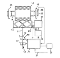
【図1】所属の制御装置を備えた巻取位置の上位領域を示す概略図である。
【符号の説明】
10 綾巻きボビン、 11 糸、 12 矢印方向、 13 巻取ドラム、14 巻管、 15,16 ボビン皿、 17 糸クリーナ、 18 切断装置、 19 糸ガイド、 20 巻取部位コンピュータ、 21 電動モータ、22 周波数変換器、 23,25 磁極ディスク、 24,26 ホールセンサ、 27 入力部、 28 プリンタ[0001]
BACKGROUND OF THE INVENTION
The present invention relates to a method for calculating the diameter of a traverse bobbin when winding a traverse bobbin with coarse winding in a winder, and the traverse bobbin is driven by friction at each winding part of the winder One take-up drum is provided so that the take-up drum generates a slip between the traverse bobbin and the take-up drum to prevent ribbon winding in the ribbon winding zone that may occur. The diameter of the traverse bobbin is calculated from the known diameter of the take-up drum and the measured rotational speed of the take-up drum and the traverse bobbin.
[0002]
[Prior art]
Such a method is known from German Offenlegungsschrift 4,339,217, in which the diameter calculation is used, for example, to define the point of exchange of a traverse bobbin for an empty winding tube according to the diameter. It is done. Moreover, it is also known in this method that the replacement of the traverse bobbin with respect to the empty winding tube is defined with respect to the yarn length that can be wound up. In this case, the yarn length to be wound is obtained by counting the number of rotations of the winding drum, and this yarn length is multiplied by the known yarn length carried out in one rotation. The occurrence of slip in the ribbon winding zone that can occur is caused by the connection and disconnection of the motor that drives the winding drum. At the set bandwidth of the speed, the speed of the winding drum is increased relatively quickly from the lower limit to the upper limit by connecting the motor, and then the motor is shut off again until the lower limit is reached. Is done. Slip occurs during motor acceleration.
[0003]
The traverse bobbin is supported on a swivelable bobbin frame, and is crimped to the winding drum with a supporting pressing force (Auflagedruck). German Patent Application No. 19829597 discloses that the support pressing force is reduced in order to generate a slip when passing through the ribbon winding zone. Or in connection with motor connection and disconnection.
[0004]
In such a method, if it is desired to replace the traverse bobbin in relation to the target yarn length, it is performed without any problems. In this case, the slip does not play an important role, and in some cases the slip takes into account a correction factor that adjusts the signal value (Ergebnis) of the winding drum speed generator, for example the incremental counter (Inkrementalzaehler), by the amount of slip. can do.
[0005]
However, a problem arises when it is desired to replace the traverse bobbin in relation to the diameter, i.e., when an adjustable diameter that attempts to stop the winding position reaches between ribbon winding zones. In this case, calculation of the diameter of the traverse bobbin using the current rotational speed ratio of the traverse bobbin and the winding drum and the diameter of the winding drum results in an error of several millimeters. This can happen frequently. This is because the time required to pass the ribbon winding zone may take several minutes.
[0006]
[Problems to be solved by the invention]
The object of the present invention is to calculate the diameter of a traverse bobbin as described at the beginning, so that it is possible to detect the diameter as reliably as possible even in the ribbon winding zone, and as a result, the diameter of the traverse bobbin set is reached. It is to provide a method capable of stopping the winding site.
[0007]
[Means for Solving the Problems]
According to the method of the present invention for solving this problem, it is possible to calculate the expected increase in diameter to calculate the current diameter of the traverse bobbin when passing through the ribbon winding zone, The diameter increase that occurs when passing through the zone is added to the traverse bobbin diameter calculated from the rotational speed ratio of the traverse bobbin and the take-up drum and the diameter of the take-up drum before reaching the ribbon winding zone. .
[0008]
【The invention's effect】
According to the method of the present invention, while passing through the ribbon winding zone, the current diameter of the traverse bobbin is estimated relatively accurately, and in some cases, when the set diameter is reached, the corresponding winding site is determined. Can be blocked.
[0009]
According to one method of the present invention, the course of time-related increase in the diameter of the twill-wound bobbin is calculated and the time while passing through the ribbon winding zone is detected. Therefore, with respect to the detected time, the diameter of the traverse bobbin existing in this time zone can be estimated relatively accurately. A time zone in which the target diameter is expected can be provided, and the winding site can be stopped after the time zone has elapsed.
[0010]
According to another method of the present invention, the course of an increase in the diameter of the cheese is whether we calculated the wound-up yarn length and the calculated diameter, the yarn length wound up while passing through the ribbon winding zone Detected. According to a simple solution, the wound yarn length can be determined by detecting the number of revolutions of the winding drum. In this case, it is a precondition that the yarn length conveyed every time the winding drum rotates is known. In this solution, the, the diameter calculated before the arrival of the ribbon winding zone, the rotational speed of the predeterminable winding drum when the target diameter of the cheese is achieved during passage through the ribbon winding zone And the target diameter is obtained.
[0011]
In order to you clearly the actual diameter of the finished cheese while passing through the ribbon winding zone, using the diameter determined from the course of the expected increase. In this way it is possible to avoid assignment of diameter indications in the traverse bobbin which are not appropriate or with errors. It is advantageous if the traverse bobbin is replaced according to the target yarn length. The diameter can be specified by printout. As a further explicit form, a display or monitor is used.
[0012]
Other methods and advantages of the present invention will be apparent from the description below.
[0013]
DETAILED DESCRIPTION OF THE INVENTION
Next, embodiments of the present invention will be described in detail using the illustrated examples.
[0014]
The winder has a plurality of winding parts that work independently from each other over a wide range, and one winding
[0015]
The
[0016]
The winding
[0017]
The winding
[0018]
As shown by the
[0019]
Based on the data of the rotational
[0020]
However, if the ribbon winding zone is located just in the region of the target diameter of the
[0021]
In this case, in order to be able to define the diameter of the
[0022]
For example, by continuously calculating the diameter of the
[0023]
In the winding portion of the above-described type, the yarn length that is conveyed every time the winding
[0024]
Even if the
[Brief description of the drawings]
FIG. 1 is a schematic diagram showing an upper region of a winding position provided with an associated control device.
[Explanation of symbols]
10 thread winding bobbin, 11 thread, 12 arrow direction, 13 winding drum, 14 winding tube, 15, 16 bobbin dish, 17 thread cleaner, 18 cutting device, 19 thread guide, 20 winding part computer, 21 electric motor, 22 Frequency converter, 23, 25 magnetic pole disk, 24, 26 Hall sensor, 27 input unit, 28 printer
Claims (4)
前記綾巻きボビン(10)と前記巻取ドラム(13)との間にスリップを発生させてリボン巻きを防止する間については、当該リボン巻きを防止する前の前記綾巻きボビン(10)の直径の、時間に関する増加の経過を算出することにより、算出した該経過を、当該リボン巻きを防止する間の、綾巻きボビン(10)の目下の直径を算出するための予想される直径の増加の経過とし、更に当該リボン巻きを防止する間の時間を検出し、検出した該時間と前記予想される直径の増加の経過とにより、当該リボン巻きを防止する際に生じる直径増加分を算出し、該直径増加分を、当該リボン巻きを防止する直前の前記綾巻きボビン(10)および前記巻取ドラム(13)の回転数比と該巻取ドラム(13)の直径とから算出された前記綾巻きボビン(10)の直径に加算することを特徴とする、綾巻きボビンの直径を算出する方法。 A method for calculating a diameter of a traverse bobbin when winding a traverse bobbin with a coarse winding in a winder, wherein each winding part of the winder drives a traverse bobbin by friction. and the drum (13) is provided, in order to prevent ribbon winding, to generate a slip between the winding drum (13) is the cheese (10) and said winding drum (13) has become manner, measured rotation speed of the known diameter, the winding-up drum (13) and the cheese (10) of the winding drum diameter of the cheese (10) (13) In the method of calculating from the ratio ,
The diameter of the traverse bobbin (10) before the ribbon winding is prevented while slippage is generated between the traverse bobbin (10) and the winding drum (13) to prevent ribbon winding. By calculating the time course of the increase in time, the calculated time course of the expected diameter increase for calculating the current diameter of the traverse bobbin (10) while preventing the ribbon winding . and passed further to detect the time between to prevent the ribbon winding, the the course of the increase in diameter which is the expected inter detected said time, and calculates the diameter increase occurring in preventing the ribbon winding, the diameter increase, the cheese (10) and the rotational speed ratio and the take-up drum (13) said Aya calculated from the diameter of the winding drum (13) just prior to prevent the ribbon winding Rolled bobby Characterized by adding to the diameter of the (10), a method of calculating the diameter of the cheese.
前記綾巻きボビン(10)と前記巻取ドラム(13)との間にスリップを発生させてリボン巻きを防止する間については、当該リボン巻きを防止する前の前記綾巻きボビン(10)の直径における増加の経過を巻き上げられた糸長さと算出した前記綾巻きボビン(10)の直径とから算出することにより、当該リボン巻きを防止する間の、綾巻きボビン(10)の目下の直径を算出するための予想される直径の増加の経過とし、更に当該リボン巻きを防止する間の巻き上げられた糸長さを検出し、検出した該糸長さと前記予想される直径の増加の経過とにより、当該リボン巻きを防止する際に生じる直径増加分を算出し、該直径増加分を、当該リボン巻きを防止する直前の前記綾巻きボビン(10)および前記巻取ドラム(13)の回転数比と該巻取ドラム(13)の直径とから算出された前記綾巻きボビン(10)の直径に加算することを特徴とする、綾巻きボビンの直径を算出する方法。The diameter of the traverse bobbin (10) before the ribbon winding is prevented while slippage is generated between the traverse bobbin (10) and the winding drum (13) to prevent ribbon winding. The current diameter of the traverse bobbin (10) is calculated while preventing the ribbon from being wound by calculating the progress of increase in yarn from the wound yarn length and the calculated diameter of the traverse bobbin (10). And the expected increase in diameter to detect the length of the wound yarn while preventing the ribbon winding, and the detected length of the yarn and the expected increase in diameter, The increase in diameter that occurs when the ribbon winding is prevented is calculated, and the increase in diameter is the rotation speed ratio of the traverse bobbin (10) and the winding drum (13) immediately before the ribbon winding is prevented. Characterized by adding to the diameter of the cheese calculated (10) from the diameter of the winding-up drum (13), a method of calculating the diameter of the cheese.
Applications Claiming Priority (2)
| Application Number | Priority Date | Filing Date | Title |
|---|---|---|---|
| DE19961982.4 | 1999-12-22 | ||
| DE19961982A DE19961982A1 (en) | 1999-12-22 | 1999-12-22 | Process for winding cross-wound bobbins |
Publications (3)
| Publication Number | Publication Date |
|---|---|
| JP2001180867A JP2001180867A (en) | 2001-07-03 |
| JP2001180867A5 JP2001180867A5 (en) | 2007-10-04 |
| JP4787404B2 true JP4787404B2 (en) | 2011-10-05 |
Family
ID=7933788
Family Applications (1)
| Application Number | Title | Priority Date | Filing Date |
|---|---|---|---|
| JP2000384311A Expired - Fee Related JP4787404B2 (en) | 1999-12-22 | 2000-12-18 | How to calculate the diameter of a traverse bobbin |
Country Status (5)
| Country | Link |
|---|---|
| US (1) | US6405965B2 (en) |
| EP (1) | EP1110896B1 (en) |
| JP (1) | JP4787404B2 (en) |
| AT (1) | ATE288872T1 (en) |
| DE (2) | DE19961982A1 (en) |
Families Citing this family (3)
| Publication number | Priority date | Publication date | Assignee | Title |
|---|---|---|---|---|
| JP2009023785A (en) * | 2007-07-19 | 2009-02-05 | Murata Mach Ltd | Yarn winding device |
| DE102008008083A1 (en) | 2008-01-28 | 2009-07-30 | Wilhelm Stahlecker Gmbh | Method and apparatus for making cross-wound packages |
| CN111232755B (en) * | 2020-01-17 | 2021-08-13 | 江苏恒力化纤股份有限公司 | Method for automatically adjusting coil diameter of wire coil to avoid abnormal formation of wire coil |
Family Cites Families (12)
| Publication number | Priority date | Publication date | Assignee | Title |
|---|---|---|---|---|
| CH663402A5 (en) | 1981-12-04 | 1987-12-15 | Loepfe Ag Geb | METHOD FOR DETERMINING THE YARN LENGTH WINDED ON A CROSS REEL WITH FRICTION DRIVE BY A SLOT DRUM. |
| DE3703869C2 (en) | 1987-02-07 | 1996-12-12 | Schlafhorst & Co W | Method for monitoring and / or controlling the winding process and winding unit for executing the method |
| DE3810365A1 (en) * | 1988-03-26 | 1989-10-05 | Schlafhorst & Co W | METHOD AND DEVICE FOR DETERMINING THE COIL SCOPE OF CRANES AND FOR EVALUATING THE RESULT |
| JPH0346966A (en) * | 1989-07-14 | 1991-02-28 | Murata Mach Ltd | Package take-up method |
| CA1330839C (en) * | 1989-08-30 | 1994-07-19 | Douglas Edward Turek | Method of predicting yarn package size |
| DE4339217A1 (en) * | 1993-11-18 | 1995-05-24 | Schlafhorst & Co W | Bobbin winder control |
| DE19619706A1 (en) * | 1995-05-29 | 1996-12-05 | Barmag Barmer Maschf | Bobbin winding |
| DE19607905B4 (en) * | 1996-03-01 | 2006-09-14 | Saurer Gmbh & Co. Kg | Method and device for producing cheeses in wild winding |
| DE19625510A1 (en) * | 1996-06-26 | 1998-01-02 | Schlafhorst & Co W | Slip size at yarn reel wound by friction roller |
| DE19625512A1 (en) * | 1996-06-26 | 1998-01-15 | Schlafhorst & Co W | Method and device for determining the diameter of a cheese |
| DE19625511A1 (en) * | 1996-06-26 | 1998-01-02 | Schlafhorst & Co W | Method and device for producing cross-wound bobbins in a wild winding |
| DE10021963A1 (en) * | 1999-05-14 | 2000-12-21 | Barmag Barmer Maschf | Winding of yarns on cross-wound packages involves arranging the variation of traverse length to ensure that turning points are spaced round periphery |
-
1999
- 1999-12-22 DE DE19961982A patent/DE19961982A1/en not_active Withdrawn
-
2000
- 2000-10-24 AT AT00122348T patent/ATE288872T1/en not_active IP Right Cessation
- 2000-10-24 DE DE50009472T patent/DE50009472D1/en not_active Expired - Lifetime
- 2000-10-24 EP EP00122348A patent/EP1110896B1/en not_active Expired - Lifetime
- 2000-12-18 JP JP2000384311A patent/JP4787404B2/en not_active Expired - Fee Related
- 2000-12-22 US US09/748,677 patent/US6405965B2/en not_active Expired - Fee Related
Also Published As
| Publication number | Publication date |
|---|---|
| ATE288872T1 (en) | 2005-02-15 |
| DE50009472D1 (en) | 2005-03-17 |
| US20010004998A1 (en) | 2001-06-28 |
| EP1110896B1 (en) | 2005-02-09 |
| JP2001180867A (en) | 2001-07-03 |
| EP1110896A2 (en) | 2001-06-27 |
| US6405965B2 (en) | 2002-06-18 |
| EP1110896A3 (en) | 2002-09-25 |
| DE19961982A1 (en) | 2001-07-05 |
Similar Documents
| Publication | Publication Date | Title |
|---|---|---|
| EP2433889B1 (en) | Yarn winding device and alarm threshold value determination method for detection of rotational faults in a package | |
| US4805844A (en) | Method and apparatus for monitoring and controlling winding operation of a winding station in a textile winding machine | |
| US4828191A (en) | Method for sorting cheeses on an automatic winding machine | |
| JP6732560B2 (en) | Method and apparatus for optimizing the density of a twill package produced in a twill winding autowinder working unit | |
| JPS62218370A (en) | Method and devoce for repeating yarn | |
| US5595351A (en) | Method for controlling a winding station of a bobbin winding machine when a take-up bobbin is changed and winding station for performing the method | |
| EP2671830B1 (en) | Textile machine, standby position determining method of driven member of winding unit, and winding unit | |
| JP6218592B2 (en) | Method for preventing ribbon winding and winding device for traverse winding package | |
| US4805846A (en) | Automatic winder | |
| JPH1072167A (en) | Manufacture of cross-wound package and device therefor | |
| JPH0192177A (en) | Method and device for obtaining speed of yarn on textile machine | |
| JP2010047406A (en) | Yarn winding device and automatic winder with the same | |
| US20200310388A1 (en) | Method for Controlling Means of a Workstation of a Textile Machine, a Device for Performing the Method and a Sensor of the State of a Workstation of a Textile Machine | |
| EP2805907B1 (en) | Yarn winding machine | |
| JP4787404B2 (en) | How to calculate the diameter of a traverse bobbin | |
| EP1795478B1 (en) | Textile machine | |
| EP1787936A2 (en) | Textile machine | |
| US5826815A (en) | Method and apparatus for determining a value of slippage in the winding of a yarn package | |
| JPH11240674A (en) | Monitoring method of paraffining | |
| EP1795477B1 (en) | Winder | |
| EP2690044B1 (en) | Yarn winding device | |
| JPS60213667A (en) | Control of length in winding of cotton | |
| JP3932950B2 (en) | Winding control monitoring device for yarn winding machine | |
| JPH09110299A (en) | Fixed quantity yarn strip winder | |
| JP4192746B2 (en) | Package weight prediction method, package manufacturing method, and yarn winder |
Legal Events
| Date | Code | Title | Description |
|---|---|---|---|
| A521 | Request for written amendment filed |
Free format text: JAPANESE INTERMEDIATE CODE: A523 Effective date: 20070821 |
|
| A621 | Written request for application examination |
Free format text: JAPANESE INTERMEDIATE CODE: A621 Effective date: 20070821 |
|
| A977 | Report on retrieval |
Free format text: JAPANESE INTERMEDIATE CODE: A971007 Effective date: 20090406 |
|
| A131 | Notification of reasons for refusal |
Free format text: JAPANESE INTERMEDIATE CODE: A131 Effective date: 20090513 |
|
| A601 | Written request for extension of time |
Free format text: JAPANESE INTERMEDIATE CODE: A601 Effective date: 20090810 |
|
| A602 | Written permission of extension of time |
Free format text: JAPANESE INTERMEDIATE CODE: A602 Effective date: 20090813 |
|
| A601 | Written request for extension of time |
Free format text: JAPANESE INTERMEDIATE CODE: A601 Effective date: 20090911 |
|
| A602 | Written permission of extension of time |
Free format text: JAPANESE INTERMEDIATE CODE: A602 Effective date: 20090916 |
|
| A601 | Written request for extension of time |
Free format text: JAPANESE INTERMEDIATE CODE: A601 Effective date: 20091009 |
|
| A602 | Written permission of extension of time |
Free format text: JAPANESE INTERMEDIATE CODE: A602 Effective date: 20091015 |
|
| A02 | Decision of refusal |
Free format text: JAPANESE INTERMEDIATE CODE: A02 Effective date: 20100303 |
|
| RD04 | Notification of resignation of power of attorney |
Free format text: JAPANESE INTERMEDIATE CODE: A7424 Effective date: 20101228 |
|
| RD13 | Notification of appointment of power of sub attorney |
Free format text: JAPANESE INTERMEDIATE CODE: A7433 Effective date: 20110215 |
|
| A521 | Request for written amendment filed |
Free format text: JAPANESE INTERMEDIATE CODE: A821 Effective date: 20110215 |
|
| A521 | Request for written amendment filed |
Free format text: JAPANESE INTERMEDIATE CODE: A523 Effective date: 20110520 |
|
| A01 | Written decision to grant a patent or to grant a registration (utility model) |
Free format text: JAPANESE INTERMEDIATE CODE: A01 |
|
| A61 | First payment of annual fees (during grant procedure) |
Free format text: JAPANESE INTERMEDIATE CODE: A61 Effective date: 20110715 |
|
| R150 | Certificate of patent or registration of utility model |
Ref document number: 4787404 Country of ref document: JP Free format text: JAPANESE INTERMEDIATE CODE: R150 Free format text: JAPANESE INTERMEDIATE CODE: R150 |
|
| FPAY | Renewal fee payment (event date is renewal date of database) |
Free format text: PAYMENT UNTIL: 20140722 Year of fee payment: 3 |
|
| S111 | Request for change of ownership or part of ownership |
Free format text: JAPANESE INTERMEDIATE CODE: R313113 |
|
| S531 | Written request for registration of change of domicile |
Free format text: JAPANESE INTERMEDIATE CODE: R313531 |
|
| S533 | Written request for registration of change of name |
Free format text: JAPANESE INTERMEDIATE CODE: R313533 |
|
| R350 | Written notification of registration of transfer |
Free format text: JAPANESE INTERMEDIATE CODE: R350 |
|
| R250 | Receipt of annual fees |
Free format text: JAPANESE INTERMEDIATE CODE: R250 |
|
| R250 | Receipt of annual fees |
Free format text: JAPANESE INTERMEDIATE CODE: R250 |
|
| R250 | Receipt of annual fees |
Free format text: JAPANESE INTERMEDIATE CODE: R250 |
|
| R250 | Receipt of annual fees |
Free format text: JAPANESE INTERMEDIATE CODE: R250 |
|
| R250 | Receipt of annual fees |
Free format text: JAPANESE INTERMEDIATE CODE: R250 |
|
| LAPS | Cancellation because of no payment of annual fees |