JP4787239B2 - Film sheet processing method and processing apparatus - Google Patents
Film sheet processing method and processing apparatus Download PDFInfo
- Publication number
- JP4787239B2 JP4787239B2 JP2007505400A JP2007505400A JP4787239B2 JP 4787239 B2 JP4787239 B2 JP 4787239B2 JP 2007505400 A JP2007505400 A JP 2007505400A JP 2007505400 A JP2007505400 A JP 2007505400A JP 4787239 B2 JP4787239 B2 JP 4787239B2
- Authority
- JP
- Japan
- Prior art keywords
- film sheet
- gripping
- film
- cutting
- edge piece
- Prior art date
- Legal status (The legal status is an assumption and is not a legal conclusion. Google has not performed a legal analysis and makes no representation as to the accuracy of the status listed.)
- Expired - Fee Related
Links
Images


Classifications
-
- B—PERFORMING OPERATIONS; TRANSPORTING
- B65—CONVEYING; PACKING; STORING; HANDLING THIN OR FILAMENTARY MATERIAL
- B65H—HANDLING THIN OR FILAMENTARY MATERIAL, e.g. SHEETS, WEBS, CABLES
- B65H23/00—Registering, tensioning, smoothing or guiding webs
- B65H23/02—Registering, tensioning, smoothing or guiding webs transversely
- B65H23/022—Registering, tensioning, smoothing or guiding webs transversely by tentering devices
- B65H23/025—Registering, tensioning, smoothing or guiding webs transversely by tentering devices by rollers
-
- B—PERFORMING OPERATIONS; TRANSPORTING
- B65—CONVEYING; PACKING; STORING; HANDLING THIN OR FILAMENTARY MATERIAL
- B65H—HANDLING THIN OR FILAMENTARY MATERIAL, e.g. SHEETS, WEBS, CABLES
- B65H20/00—Advancing webs
- B65H20/02—Advancing webs by friction roller
-
- B—PERFORMING OPERATIONS; TRANSPORTING
- B65—CONVEYING; PACKING; STORING; HANDLING THIN OR FILAMENTARY MATERIAL
- B65H—HANDLING THIN OR FILAMENTARY MATERIAL, e.g. SHEETS, WEBS, CABLES
- B65H2301/00—Handling processes for sheets or webs
- B65H2301/40—Type of handling process
- B65H2301/41—Winding, unwinding
- B65H2301/414—Winding
- B65H2301/41419—Starting winding process
- B65H2301/41427—Starting winding process involving arrangements for securing leading edge to core, e.g. adhesive tape
-
- B—PERFORMING OPERATIONS; TRANSPORTING
- B65—CONVEYING; PACKING; STORING; HANDLING THIN OR FILAMENTARY MATERIAL
- B65H—HANDLING THIN OR FILAMENTARY MATERIAL, e.g. SHEETS, WEBS, CABLES
- B65H2301/00—Handling processes for sheets or webs
- B65H2301/40—Type of handling process
- B65H2301/41—Winding, unwinding
- B65H2301/417—Handling or changing web rolls
- B65H2301/4187—Relative movement of core or web roll in respect of mandrel
- B65H2301/4189—Cutting
- B65H2301/41898—Cutting threading tail and leading it to new core
-
- B—PERFORMING OPERATIONS; TRANSPORTING
- B65—CONVEYING; PACKING; STORING; HANDLING THIN OR FILAMENTARY MATERIAL
- B65H—HANDLING THIN OR FILAMENTARY MATERIAL, e.g. SHEETS, WEBS, CABLES
- B65H2301/00—Handling processes for sheets or webs
- B65H2301/50—Auxiliary process performed during handling process
- B65H2301/52—Auxiliary process performed during handling process for starting
- B65H2301/522—Threading web into machine
- B65H2301/52202—Threading web into machine around several subsequent rollers (e.g. calendar)
-
- Y—GENERAL TAGGING OF NEW TECHNOLOGICAL DEVELOPMENTS; GENERAL TAGGING OF CROSS-SECTIONAL TECHNOLOGIES SPANNING OVER SEVERAL SECTIONS OF THE IPC; TECHNICAL SUBJECTS COVERED BY FORMER USPC CROSS-REFERENCE ART COLLECTIONS [XRACs] AND DIGESTS
- Y10—TECHNICAL SUBJECTS COVERED BY FORMER USPC
- Y10T—TECHNICAL SUBJECTS COVERED BY FORMER US CLASSIFICATION
- Y10T156/00—Adhesive bonding and miscellaneous chemical manufacture
- Y10T156/10—Methods of surface bonding and/or assembly therefor
- Y10T156/1052—Methods of surface bonding and/or assembly therefor with cutting, punching, tearing or severing
- Y10T156/1062—Prior to assembly
- Y10T156/1067—Continuous longitudinal slitting
-
- Y—GENERAL TAGGING OF NEW TECHNOLOGICAL DEVELOPMENTS; GENERAL TAGGING OF CROSS-SECTIONAL TECHNOLOGIES SPANNING OVER SEVERAL SECTIONS OF THE IPC; TECHNICAL SUBJECTS COVERED BY FORMER USPC CROSS-REFERENCE ART COLLECTIONS [XRACs] AND DIGESTS
- Y10—TECHNICAL SUBJECTS COVERED BY FORMER USPC
- Y10T—TECHNICAL SUBJECTS COVERED BY FORMER US CLASSIFICATION
- Y10T156/00—Adhesive bonding and miscellaneous chemical manufacture
- Y10T156/10—Methods of surface bonding and/or assembly therefor
- Y10T156/1052—Methods of surface bonding and/or assembly therefor with cutting, punching, tearing or severing
- Y10T156/108—Flash, trim or excess removal
-
- Y—GENERAL TAGGING OF NEW TECHNOLOGICAL DEVELOPMENTS; GENERAL TAGGING OF CROSS-SECTIONAL TECHNOLOGIES SPANNING OVER SEVERAL SECTIONS OF THE IPC; TECHNICAL SUBJECTS COVERED BY FORMER USPC CROSS-REFERENCE ART COLLECTIONS [XRACs] AND DIGESTS
- Y10—TECHNICAL SUBJECTS COVERED BY FORMER USPC
- Y10T—TECHNICAL SUBJECTS COVERED BY FORMER US CLASSIFICATION
- Y10T156/00—Adhesive bonding and miscellaneous chemical manufacture
- Y10T156/12—Surface bonding means and/or assembly means with cutting, punching, piercing, severing or tearing
-
- Y—GENERAL TAGGING OF NEW TECHNOLOGICAL DEVELOPMENTS; GENERAL TAGGING OF CROSS-SECTIONAL TECHNOLOGIES SPANNING OVER SEVERAL SECTIONS OF THE IPC; TECHNICAL SUBJECTS COVERED BY FORMER USPC CROSS-REFERENCE ART COLLECTIONS [XRACs] AND DIGESTS
- Y10—TECHNICAL SUBJECTS COVERED BY FORMER USPC
- Y10T—TECHNICAL SUBJECTS COVERED BY FORMER US CLASSIFICATION
- Y10T156/00—Adhesive bonding and miscellaneous chemical manufacture
- Y10T156/17—Surface bonding means and/or assemblymeans with work feeding or handling means
- Y10T156/1702—For plural parts or plural areas of single part
- Y10T156/1712—Indefinite or running length work
-
- Y—GENERAL TAGGING OF NEW TECHNOLOGICAL DEVELOPMENTS; GENERAL TAGGING OF CROSS-SECTIONAL TECHNOLOGIES SPANNING OVER SEVERAL SECTIONS OF THE IPC; TECHNICAL SUBJECTS COVERED BY FORMER USPC CROSS-REFERENCE ART COLLECTIONS [XRACs] AND DIGESTS
- Y10—TECHNICAL SUBJECTS COVERED BY FORMER USPC
- Y10T—TECHNICAL SUBJECTS COVERED BY FORMER US CLASSIFICATION
- Y10T156/00—Adhesive bonding and miscellaneous chemical manufacture
- Y10T156/17—Surface bonding means and/or assemblymeans with work feeding or handling means
- Y10T156/1798—Surface bonding means and/or assemblymeans with work feeding or handling means with liquid adhesive or adhesive activator applying means
-
- Y—GENERAL TAGGING OF NEW TECHNOLOGICAL DEVELOPMENTS; GENERAL TAGGING OF CROSS-SECTIONAL TECHNOLOGIES SPANNING OVER SEVERAL SECTIONS OF THE IPC; TECHNICAL SUBJECTS COVERED BY FORMER USPC CROSS-REFERENCE ART COLLECTIONS [XRACs] AND DIGESTS
- Y10—TECHNICAL SUBJECTS COVERED BY FORMER USPC
- Y10T—TECHNICAL SUBJECTS COVERED BY FORMER US CLASSIFICATION
- Y10T83/00—Cutting
- Y10T83/04—Processes
- Y10T83/0405—With preparatory or simultaneous ancillary treatment of work
- Y10T83/0419—By distorting within elastic limit
- Y10T83/0424—By stretching
-
- Y—GENERAL TAGGING OF NEW TECHNOLOGICAL DEVELOPMENTS; GENERAL TAGGING OF CROSS-SECTIONAL TECHNOLOGIES SPANNING OVER SEVERAL SECTIONS OF THE IPC; TECHNICAL SUBJECTS COVERED BY FORMER USPC CROSS-REFERENCE ART COLLECTIONS [XRACs] AND DIGESTS
- Y10—TECHNICAL SUBJECTS COVERED BY FORMER USPC
- Y10T—TECHNICAL SUBJECTS COVERED BY FORMER US CLASSIFICATION
- Y10T83/00—Cutting
- Y10T83/04—Processes
- Y10T83/0448—With subsequent handling [i.e., of product]
- Y10T83/0467—By separating products from each other
-
- Y—GENERAL TAGGING OF NEW TECHNOLOGICAL DEVELOPMENTS; GENERAL TAGGING OF CROSS-SECTIONAL TECHNOLOGIES SPANNING OVER SEVERAL SECTIONS OF THE IPC; TECHNICAL SUBJECTS COVERED BY FORMER USPC CROSS-REFERENCE ART COLLECTIONS [XRACs] AND DIGESTS
- Y10—TECHNICAL SUBJECTS COVERED BY FORMER USPC
- Y10T—TECHNICAL SUBJECTS COVERED BY FORMER US CLASSIFICATION
- Y10T83/00—Cutting
- Y10T83/323—With means to stretch work temporarily
Abstract
Description
本発明は、フィルムシートの加工法及び加工装置に関するものである。 The present invention relates to a film sheet processing method and processing apparatus.
その際、本発明は、従来技術(例えば、下記特許文献1)から公知の一軸又は二軸のフィルム延伸装置に基づくものである。
In this case, the present invention is based on a uniaxial or biaxial film stretching apparatus known from the prior art (for example,
一軸延伸又は二軸延伸を実施した後に、対応して製造されるフィルムは、公知の如く、ローラ装置(所謂排出台、引張りロール)の種々の工程及び試験区域を通って案内され、巻上装置で巻上げられる。通常、フィルムシートは、所謂開放式の引き込みスリットにより操作者の手でフィルム延伸装置から排出台及び巻上装置に引き込まれる。その際、巻付けられるローラにフィルム経路を交互に追従させなければならず、機械フレームの一部を把持しなければならない。従って、一方で、引き込み速度が操作者の生理学的特性により制限され、他方で、開放式の引き込みスリット(所謂C型柱状構造)により、使用される建物のコストが明らかに高くなる。 After carrying out uniaxial or biaxial stretching, the correspondingly produced film is guided through various processes and test areas of a roller device (so-called discharge table, pulling roll) as known in the art. It is wound up with. Usually, the film sheet is drawn from the film stretching device to the discharge table and the hoisting device by the operator's hand through a so-called open type drawing slit. At that time, the film path must be alternately followed by the roller to be wound, and a part of the machine frame must be gripped. Thus, on the one hand, the retraction speed is limited by the physiological characteristics of the operator, and on the other hand, the open retraction slit (so-called C-column structure) significantly increases the cost of the building used.
前記C型柱状構造は、交互に上方及び下方にローラを支持する構造原理に関する。図18Bに示す概略横断面図では、ローラ装置の一側のC型柱状体2bにより従来技術による所謂C型柱状構造を備えた適宜の装置を表わす。これにより、図18Bの断面で示す引き込みスリットEを介して装置内にフィルムの先行する始端を引き込むために、操作者が通過する長手方向通路をC型柱状体の側部に形成される。引き込みスリットEは、機械駆動式構造部品、特に回転するローラの前の操作者を保護するために付加的に必要である安全格子内に構成される。 The C-type columnar structure relates to a structural principle for alternately supporting the rollers upward and downward. In the schematic cross-sectional view shown in FIG. 18B, an appropriate device having a so-called C-shaped columnar structure according to the prior art is represented by a C-shaped columnar body 2b on one side of the roller device. Accordingly, a longitudinal passage through which an operator passes is formed in the side portion of the C-shaped columnar body in order to draw the preceding leading end of the film into the apparatus through the drawing slit E shown in the cross section of FIG. 18B. The lead-in slit E is configured in a safety grid which is additionally necessary to protect the operator in front of the mechanically driven structural parts, in particular the rotating roller.
一側で所謂操作者側で排出台に通されるフィルムは、排出台を通って全幅で搬送され、次に、巻上装置の所謂スクラップ位置で廃フィルムが空の巻上スリーブ又は巻上ローラ上に巻上げられる。フィルムが皺なしに幅方向に引張されて、適宜の品質基準が満たされて初めて、更なる加工のために決められた巻上ロールへの最終の巻上げが行なわれる。 The film that is passed on one side to the discharge table on the so-called operator side is conveyed in full width through the discharge table, and then the winding film or the winding roller in which the waste film is empty at the so-called scrap position of the winding device Rolled up. Only when the film is pulled in the width direction without wrinkles and the appropriate quality criteria are met, the final winding on the hoisting roll determined for further processing takes place.
従来から公知の装置によるフィルムシートの手動の引き込みは、前記欠点を有し、特に操作者は、ローラ装置を通してフィルムを引き込む所定の時間を必要とし、それにより始動の際又はフィルム裂断後の装置全体の中断時間が更に増大する。 Manual pulling of film sheets by means of hitherto known devices has the disadvantages mentioned above, and in particular the operator requires a certain time to pull the film through the roller device, so that the device at start-up or after film tearing. The overall interruption time is further increased.
また、幅延伸機から排出台への移送工程及び排出台から巻上装置への移送工程は、始動過程で速度が制限され特に安全上重要な要素である。 In addition, the transfer process from the width drawing machine to the discharge table and the transfer process from the discharge table to the hoisting device are particularly important in terms of safety because the speed is limited in the starting process.
また、駆動されるローラも、ローラ台の高価な構造となり、それにより排出台のローラを支持するより狭い引き込みスリットを設けなければならない。 The driven roller also has an expensive structure for the roller base, thereby providing a narrower pull-in slit that supports the roller on the discharge base.
部分的に他の解決法の原理に関連し又は例えば紙シートのような他の材料の加工にも関する解決法が従来技術から知られている。 Solutions are known from the prior art which are partly related to the principle of other solutions or also related to the processing of other materials, for example paper sheets.
下記特許文献2は、合成材料から成るアダプタを介してローラ装置に供給すべき紙を供給する紙供給装置を示す。
下記特許文献3は、空圧式搬送装置を介して巻上装置に搬送されるフィルムテープを切断するフィルムシートを処理する方法及び装置に関する。
The following
下記特許文献4は、爪に移送される縁部片が切断され、フィルムを二軸フィルム延伸装置内に通す装置及び方法を示す。
下記特許文献5は、レール構造の上を走行する電動台車により紙シートの始端を搬送し、回転式印刷機に紙シートを引き込む装置を示す。 Japanese Patent Application Laid-Open No. H10-228561 shows an apparatus that conveys the leading end of a paper sheet by an electric carriage that runs on a rail structure and draws the paper sheet into a rotary printing machine.
前記公報及び公知の従来技術では、フィルム延伸装置での搬送手順のより迅速でより安全な全過程を保証することができない。
本発明の課題は、それにより始動時及び例えば発生したフィルム裂断後にも、フィルム延伸装置全体の中断時間を短縮して、フィルムシートを加工する加工法及び加工装置を提供することにある。さらに、本発明の課題は、従来より簡単に構成されかつローラに巻回されるフィルムシートを製造する製造装置を提供することにある。 An object of the present invention is to provide a processing method and a processing apparatus for processing a film sheet by shortening the interruption time of the entire film stretching apparatus at the time of start-up and after, for example, generated film tearing. Furthermore, the subject of this invention is providing the manufacturing apparatus which manufactures the film sheet which is comprised more simply than before and is wound around a roller.
本発明では、この課題を独立請求項により解決する。本発明の好適な実施の形態及び他の構成を従属請求項に示す。 The present invention solves this problem by the independent claims. Preferred embodiments and other configurations of the invention are indicated in the dependent claims.
本発明では、従来の解決法に対して多数の利点を実現することができる。その際、最も重要な利点は、下記の通りである。
本発明の範囲内で、始動過程及び中断時間を短縮することができる。また、本発明の範囲内で、より安全な始動又は開始及び全体としてより安全なフィルム延伸装置の作動が可能である。
本発明では、故障発生率も全体として低減される。
中断時間の低減によって、本発明の範囲内で、初めて180m/分を超える引き込み速度も可能であり、それにより結局再び生産能力が明らかに高められるので、全体としてより高い装置速度を達成できる。
特に装置の始動時でのフィルム延伸装置の操作者に対する安全性が明らかに改良される。
従来技術による所謂C型柱状構造を放棄できるので、本発明によって、排出台及び巻上接触ローラ台の所謂操作側を、駆動側と同様の構造に置き換えられ、装置のコストを低減できる。
The present invention can realize a number of advantages over conventional solutions. In that case, the most important advantages are as follows.
Within the scope of the invention, the starting process and the interruption time can be shortened. Also, within the scope of the present invention, safer starting or starting and overall safer film stretching apparatus operation are possible.
In the present invention, the failure occurrence rate is also reduced as a whole.
Due to the reduction of the interruption time, it is possible for the first time to withdraw at speeds exceeding 180 m / min within the scope of the invention, so that the production capacity is obviously increased again, so that a higher apparatus speed as a whole can be achieved.
In particular, the safety for the operator of the film stretching apparatus at the start-up of the apparatus is clearly improved.
Since the so-called C-shaped columnar structure according to the prior art can be abandoned, according to the present invention, the so-called operation side of the discharge table and the hoisting contact roller table can be replaced with the same structure as the drive side, and the cost of the apparatus can be reduced.
その際、本発明は、特にその組合せで決まる改良となる多くの利点を生ずる手段を含む。 In so doing, the present invention includes means for producing a number of advantages, particularly improvements determined by the combination.
本発明では、フィルムシートは、まず縦方向に切断される。これにより、縁部片と、次に主フィルムシートと呼ばれる縁部の分だけ小さいフィルムシートとが形成される。フィルムシートの全幅のほぼ5から10%、特に少なくとも100から200mmの幅を縁部片に設けるのが好ましい。縁部片及び主フィルムシートは、その所定の時点までに、その各先行シートから横方向に分離される。その際、後続のフィルムシートからの各先行シートの分離過程は、既に縁部片の把持搬送装置への移送の前に始まり、移送後に完了することができる。 In the present invention, the film sheet is first cut in the longitudinal direction. As a result, an edge piece and a film sheet that is smaller than the edge called the main film sheet are formed. It is preferred to provide the edge piece with a width of approximately 5 to 10% of the total width of the film sheet, in particular at least 100 to 200 mm. The edge piece and the main film sheet are separated laterally from their respective preceding sheets by the predetermined point in time. In so doing, the separation process of each preceding sheet from the subsequent film sheets can already begin before the transfer of the edge piece to the gripping and conveying device and can be completed after the transfer.
縁部片の縦方向切断及び/又は主フィルムシートの横方向切断を移動可能な切断装置により自動的に行なうことが好ましい。しかしながら、他の構成では、手動又は半手動でも切断を行なうこともできる。実際には、必要に応じて、主フィルムシートの全有効幅に亘って横向きに切断しなくてもよい。引張力の下でフィルムが横方向に切れるので、一部の幅に亘ってのみ主フィルムシートに切れ目を入れれば十分な場合もある。 It is preferable to automatically perform the longitudinal cutting of the edge piece and / or the horizontal cutting of the main film sheet by a movable cutting device. However, in other configurations, cutting can be done manually or semi-manually. In practice, if necessary, it may not be cut laterally over the entire effective width of the main film sheet. Since the film is cut transversely under tensile force, it may be sufficient to cut the main film sheet only over a portion of the width.
本発明の装置では、フィルム延伸装置の出口領域に切断装置を配置するのが好ましい。 In the apparatus of the present invention, it is preferable to arrange a cutting device in the exit region of the film stretching apparatus.
垂直に整列する回転軸の周りに切断装置を回転可能に配置して、切断装置により縁部片を縦方向に切断し、主フィルムシートを横方向に切断できることが好ましい。切断工具は、例えば一体化された駆動装置により駆動できる回転刃を含むことが好ましい。 It is preferable that a cutting device is rotatably arranged around a rotation axis aligned vertically, the edge piece can be cut in the vertical direction by the cutting device, and the main film sheet can be cut in the horizontal direction. The cutting tool preferably includes a rotary blade that can be driven by, for example, an integrated driving device.
また、好適な構成では、切断工程中のフィルムシートの更なる裂断を阻止する所謂固定装置が切断装置に設けられる。切断装置の回転軸に固定装置を配置するのが好ましく、フィルムの上方又は下方に固定ローラを設けるのが好ましい。その際、フィルムシートの切断方向にて切断装置の前方に先行して固定ローラを配置するので、切断工程中に、固定ローラを超えて制御できない裂断が発生しない。従って、固定ローラは、切断工具の直近に配置される。 Also, in a preferred configuration, the cutting device is provided with a so-called fixing device that prevents further tearing of the film sheet during the cutting process. It is preferable to arrange a fixing device on the rotating shaft of the cutting device, and it is preferable to provide a fixing roller above or below the film. At that time, since the fixed roller is arranged in front of the cutting device in the cutting direction of the film sheet, the tearing that cannot be controlled beyond the fixed roller does not occur during the cutting process. Accordingly, the fixed roller is disposed in the immediate vicinity of the cutting tool.
フィルムシートの排出方向に対して予め選択可能な角度でかつフィルムシートの有効幅に亘ってフィルム延伸装置の出口に設けた切断装置を移動して、主フィルムシートを横方向に切断するできることが好ましい。 It is preferable that the main film sheet can be cut in the transverse direction by moving a cutting device provided at the exit of the film stretching device over an effective width of the film sheet at a preselectable angle with respect to the discharge direction of the film sheet. .
本発明の更なる実施の形態では、以下の数変形例で可能なように、縁部片の縦方向切断の後に、主フィルムシートの横方向切断に対して切断装置を位置決めできる。即ち、
一部の幅に亘ってのみ主フィルムシートを切断し、その後、引張力により横方向に完全にフィルムを切ることができる。このために、固定ローラの除去が必要な場合もある。
把持搬送装置とは反対側の駆動側でフィルム縁部の近くまで、主フィルムシートが横方向に切断される。フィルム延伸装置の走行クリップとの衝突を回避するために、再び切断装置を回転し、把持搬送装置とは反対側の駆動側に沿って第二の縦方向の縁部片を切断する。その後、第二の縁部片は、フィルム延伸装置から排出され、操作者により手動で第二の横方向切断装置により分離される。
前記可能性とは別に、切断工程をクリップの移動と同期させて、特に互いに連続する2つのクリップ間でフィルムシートを完全に切断し、フィルムの全排出幅に亘って切断することも可能である。
既にクリップからフィルムを開放するフィルムの進行方向の一位置で切断装置が作動される。このために、切断装置は、対向するガイドレールの後側に案内される。従って、横方向の切断装置は、主フィルムシートを完全に切断することができる。従って、第二の縦方向切断は、省略される。
In a further embodiment of the invention, the cutting device can be positioned with respect to the transverse cut of the main film sheet after the longitudinal cut of the edge piece, as is possible in the following several variants. That is,
The main film sheet can be cut only over a portion of the width, and then the film can be cut completely in the transverse direction by tensile force. For this reason, it may be necessary to remove the fixed roller.
The main film sheet is cut in the transverse direction to the vicinity of the film edge on the driving side opposite to the gripping and conveying device. In order to avoid a collision with the running clip of the film stretching device, the cutting device is rotated again, and the second longitudinal edge piece is cut along the drive side opposite to the gripping and conveying device. Thereafter, the second edge piece is ejected from the film stretching device and manually separated by the operator with a second transverse cutting device.
Apart from the above possibilities, it is also possible to synchronize the cutting process with the movement of the clips, in particular to completely cut the film sheet between two consecutive clips and cut over the entire discharge width of the film. .
The cutting device is actuated at one position in the direction of film travel which already releases the film from the clip. For this purpose, the cutting device is guided to the rear side of the opposing guide rail. Therefore, the transverse cutting device can completely cut the main film sheet. Thus, the second longitudinal cut is omitted.
続いて、縁部片は、把持搬送装置に移送される。 Subsequently, the edge piece is transferred to the gripping and conveying device.
その際、手動、半手動又は完全自動で把持搬送装置への移送を行なえることが好ましい。 At that time, it is preferable that transfer to the gripping and conveying apparatus can be performed manually, semi-manually or fully automatically.
操作者は、縁部片を受け取って、その縁部片を手動で前記把持搬送装置内に導入するのが最も簡単な場合である。 In the simplest case, the operator receives the edge piece and manually introduces the edge piece into the gripping and conveying apparatus.
半自動の移送の場合に、例えば、フィルム延伸装置の転回部(反転部)の近くでフィルムシートを受け取り、危険区画から搬送することができる。その後、まず縁部片の切断及び横方向切断を行うことが好ましい。次に、操作者は、切り口を受け取って、それを把持搬送装置の爪内に挿入することができ、それにより把持搬送装置の台車が走り出し、フィルムシートが後続の排出台装置内を通り得る。 In the case of semi-automatic transfer, for example, a film sheet can be received near the turning section (reversing section) of the film stretching apparatus and transported from the danger zone. Thereafter, it is preferred to first cut the edge pieces and cut in the transverse direction. Next, the operator can receive the cut and insert it into the claws of the gripping and conveying device, so that the carriage of the gripping and conveying device can run and the film sheet can pass through the subsequent discharge table device.
その際、フィルムシートを実質的に水平方向に案内する締付及び/又は吸引装置により前記移送装置を構成することが好ましい。本発明の好適な実施形態では、コンベヤベルト(所謂ベルトフィーダ)又は例えば真空テーブル等を使用し、それは例えば、パンタグラフ形態の昇降装置によってフィルム面まで持ち上げることができる。把持搬送装置の爪を備えた台車がフィルムシートを通すために走り出した後、例えば所謂「ベルトフィーダ」の形態の移送装置が再び降下される。 In that case, it is preferable that the said transfer apparatus is comprised by the clamping | tightening and / or suction apparatus which guide a film sheet to a horizontal direction substantially. In a preferred embodiment of the present invention, a conveyor belt (so-called belt feeder) or a vacuum table, for example, is used, which can be lifted up to the film surface by means of a lifting device in the form of a pantograph, for example. After the carriage provided with the grips of the gripping and conveying device starts to run through the film sheet, the transfer device, for example in the form of a so-called “belt feeder”, is lowered again.
しかしながら、適宜に切断されたフィルムシートの把持搬送装置への完全自動式の移送も更に行なうことができる。 However, fully automatic transfer of the appropriately cut film sheet to the gripping and conveying apparatus can also be performed.
本発明のこの好適な完全自動式の実施の形態では、フィルム引き込み装置の一部である把持搬送装置は、フィルム延伸装置の出口領域まで移動し、その後縁部片を自動的に把持して、縁部片を移送する。これにより、縁部片の把持搬送装置への自動移送が可能になる。縁部片の移送の際に、縁部片を横向きに切断することが更に好ましい。 In this preferred fully automatic embodiment of the present invention, the gripping and conveying device that is part of the film drawing device moves to the exit area of the film stretching device and automatically grips the trailing edge piece, Transfer the edge piece. As a result, the edge piece can be automatically transferred to the gripping and conveying apparatus. More preferably, the edge piece is cut sideways during the transfer of the edge piece.
把持搬送装置は、前記のように、フィルムの縁部片を把持する一体化された把持及び/又は締付機構、駆動装置及び搬送レールから成る移動可能な把持搬送装置を含む。締め付けられたフィルムは、ローラ装置の一側に沿う与えられた進路に沿って進み、フィルムシートをローラ装置内に通す。 As described above, the gripping and transporting device includes a movable gripping and transporting device including an integrated gripping and / or tightening mechanism for gripping an edge piece of a film, a driving device, and a transporting rail. The clamped film travels along a given path along one side of the roller device and passes the film sheet through the roller device.
フィルム延伸装置の出口領域からローラ装置の一側及び巻上装置の一側に沿って延伸するベルト状の搬送レール上を移動可能である一つ又は多数の駆動ローラを備えた、電気的及び/又は機械的に駆動される台車を把持搬送装置の駆動装置に設けることが好ましい。 Electrical and / or with one or multiple drive rollers that are movable on a belt-like transport rail extending from the exit region of the film stretching device along one side of the roller device and one side of the winding device Alternatively, it is preferable to provide a mechanically driven carriage in the driving device of the gripping and conveying device.
蓄電池又は搬送レールと並んで配置された導体レールを介して駆動ユニットにエネルギを供給することが好ましい。駆動ローラの一つ又はそれ以上は、搬送レールとの良好な摩擦係合(ロック)を可能にするため、高摩擦係数の表面コーティングを備える。また、駆動ローラが搬送レールに対して押圧される押圧装置を台車に設けてもよい。 It is preferable to supply energy to the drive unit via a conductor rail arranged alongside the storage battery or the transport rail. One or more of the drive rollers are provided with a high coefficient of friction surface coating to allow good frictional engagement (locking) with the transport rail. Moreover, you may provide the pressing device in which a drive roller is pressed with respect to a conveyance rail in a trolley | bogie.
最後に、フィルムは、巻上装置の終端位置まで搬送され、そこで把持搬送装置上で爪が縁部片を開放し、それによりフィルムシートは、フィルムへの前記粘着剤の塗布後に、巻上装置上に巻上げられる。 Finally, the film is conveyed to the end position of the hoisting device, where the nail releases the edge piece on the gripping and conveying device, so that the film sheet is applied after the application of the adhesive to the film. Rolled up.
把持搬送装置は、移送開始位置と巻上装置にフィルムを巻上げる開放位置との間で例えば往復して交互に移動できる。他の構成では、閉じた循環レール装置も可能である。 The gripping and conveying device can alternately move, for example, in a reciprocating manner between a transfer start position and an open position for winding the film on the hoisting device. In other configurations, a closed circulating rail device is also possible.
本発明の更なる有利な実施の形態では、巻上装置の一側に沿う領域で好ましくは自動的に、例えば移動又は回転により搬送レールの一部が制御される。 In a further advantageous embodiment of the invention, a part of the transport rail is controlled, preferably automatically, for example by movement or rotation, in a region along one side of the hoisting device.
本発明による装置では、更に、把持搬送装置の終端位置にて、把持搬送装置の爪を開放する開放機構を配置できる。この場合、開放機構は、好ましくは開放キーである。 In the apparatus according to the present invention, an opening mechanism for opening the claws of the gripping and conveying apparatus can be further arranged at the end position of the gripping and conveying apparatus. In this case, the opening mechanism is preferably an opening key.
また、巻上装置の領域内にて、粘着剤をフィルムシート上に塗布できる塗布装置を設けてもよい。巻上装置のある位置でのフィルムシートの有無を探知できる検出装置又は検出センサに塗布装置を作動連結することが好ましい。 Moreover, you may provide the coating device which can apply | coat an adhesive on a film sheet in the area | region of a winding apparatus. It is preferable that the coating device is operatively connected to a detection device or a detection sensor that can detect the presence or absence of a film sheet at a certain position of the hoisting device.
本発明の実施の形態を添付図面について以下説明する。 Embodiments of the present invention will be described below with reference to the accompanying drawings.
図1は、フィルム処理装置、即ちフィルム延伸装置1の出口、種々の移動及び試験区域を備える排出台2及び本発明の一実施の形態による巻上装置3を示す側面図である。屈曲する二点鎖線によりフィルム4の進路を示す。
FIG. 1 is a side view showing a film processing apparatus, that is, an outlet of a
フィルム又はフィルムシート4は、フィルム延伸装置1の出口から多数の支持ローラ2a及びローラ台2bを備える排出台2を通り案内される。排出台2を通過したフィルム4は、巻上装置3に供給され、巻上装置3では、フィルム4は、粘着剤が塗布された後に、所謂スクラップの巻上スリーブ、即ち巻上ローラ8上に巻上げられる。
The film or
巻上装置3では、全有効幅にわたりフィルムシート4が整列されかつ所望の品質要求を満たしながら、スクラップローラ8上に巻上げられる。
In the
次に、フィルムシート4は、横方向の切断刃を有する切断アーム7により切断された後に、巻上ローラ9(逆巻上工程)上に巻上げられる。
Next, after the
フィルム延伸装置1の出口領域に設けられる切断装置11(図1には図示しない)によりフィルム4の縁部片4aを切断し、その後、フィルム延伸装置1と巻上装置3の間でフィルム4を搬送するときに、操作者5は、フィルム4の縁部片4aを把持して、フィルム引込装置を構成する把持搬送装置10内に縁部片4aを装入し、把持搬送装置10により縁部片4を把持し、把持搬送装置10を移動することにより、把持搬送装置10によりフィルム4が移送される。フィルム4の搬送時に、把持搬送装置10は、ローラ装置2及び巻上装置3の一側に沿って屈曲する搬送レール15上を移動し、更に巻上装置3の終端位置Pから搬送レール15に沿って再び操作者5まで戻ることができる。このため、図1の側面図に屈曲して示す搬送レール15(後述する)は、フィルムシート4の通過に対応して巻上装置3まで案内する搬送通路を形成し、フィルムシート4の先行する前端部は、多数のローラ装置2に設けられる支持ローラ2aにより巻上装置3に搬送される。
The edge piece 4a of the
操作者5が把持搬送装置10内にフィルムシート4の縁部片4aを装入した後、操作者5は、把持搬送装置10から突出する縁部片4aの前方の部分を切断ユニット6により切断することができる。図1に示す実施の形態では、縁部片4aの切断後に、縁部片4aに続く主フィルムシート4は、操作者又は複数の操作者5により手動で切り離される。フィルムシート4に既に形成されたより短い切れ目から、現存するフィルムシート4を引張するときに発生する引張応力により、フィルムシート4の切れ目の残りの部分を十分に裂断できる場合もある。
After the operator 5 inserts the edge piece 4 a of the
最後に、把持搬送装置10は、搬送レール15に沿って移動し、フィルムシート4は、フィルムシート4の縁部片4aによりローラ装置2の支持ローラ2aに引き込まれる。把持搬送装置10は、フィルムシート4又はフィルムシート4の縁部片4aを把持する把持装置を構成する爪10aを備え、搬送レール15上を移動可能な台車等を構成する把持搬送装置10の構成を後に詳細に説明する。支持ローラ2aは、ローラ装置2の搬送レール15に対向する側に設けられるローラ装置2のローラ駆動装置により公知の方法で駆動される。
Finally, the gripping and conveying
従って、縁部片4aの前記切断により形成されるフィルムシート4の搬送紐である縁部片4aをローラ装置2に装入することができる。この場合、ローラ装置2の支持ローラ2aとローラ台2bとの間に搬送レール15が配置されるため、従来とは逆に、ローラ装置2の引込み側での複雑な柱状構造を省略できる。
Therefore, the edge piece 4a, which is a transport string of the
把持搬送装置10は、ローラ装置2を通過した後、巻上装置3内に進み、まず巻上ローラ8及び9のそばを通って搬送レール15により案内される。最後に、把持搬送装置10は、停止位置Pに達し、フィルムシート4の縁部片4aは、把持搬送装置10から停止位置Pで解放され、スクラップ式巻上ローラ8に当接する。フィルム4の適宜の位置に粘着剤又は接着剤が塗布され、接着剤を介してスクラップ式巻上ローラ8にフィルム4の始端が保持される。最後に、フィルムシート4は、スクラップ式巻上ローラ8に巻上げられる。
After passing through the
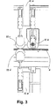
以下に、本発明によるフィルムシート4の切断工程及び関連する切断装置の可能な実施の形態を図2及び図3について説明する。
In the following, possible embodiments of the cutting process of the
図2は、フィルム延伸装置1の出口領域を通過するフィルムシート4の平面図を示す。公知のように、フィルム延伸装置1に設けられる図2に略示する複数の所謂クリップ1aは、フィルムシート4を把持しかつ搬送する。図2の線Cは、冷却ゾーンの終端を示し、線Kは、フィルムシート4の縁部をクリップ1aから解放する開放位置を示す所謂クリップ外し線を示す。
FIG. 2 shows a plan view of the
操作者が近付き難い破線で示すほぼ長方形の安全区画Sが出口領域に設けられる。後述するが、略示する切断装置11が安全区画Sに設けられる。操作者5側でクリップ1aにより未だ保持されるフィルムシート4のフィルム延伸装置1内の領域に切断装置11が配置される。これにより、フィルムシート4の切断に必要な張力が保持される。図2は、操作者5は、フィルムシート4の長さ方向、即ち側縁に沿ってフィルムシート4を切断装置11により切断して、フィルムシート4の縁部片4aと主フィルムシート4bとを形成することを示す。図2に示す実施の形態では、操作者5は、把持搬送装置10内に縁部片4aを装入し、次に主フィルムシート4bを分離し、操作者は、主フィルムシート4bの先行するシート4b’及び縁部片4aの前端を手動で切り離す。図2は、前端の切断を二つの鋏により図示する。最後に、把持搬送装置10により縁部片4aを搬送し、それによりフィルムシート4は、排出台2及び巻上装置3に搬送される。
A substantially rectangular safety section S indicated by a broken line that is difficult for an operator to approach is provided in the exit area. As will be described later, a cutting
図3は、本発明による方法の一実施の形態に使用する切断装置11と固定装置との詳細な側面図を示す。図3の側面図に示すように、切断装置11は、回転軸11aに軸支され、回転軸11aの右側に調整可能な切断刃11bが設けられ、回転軸11aの左側に調整可能な固定装置となる固定ローラ11cと11dとが取り付けられる。切断装置11は、切断刃11b及び固定装置と共に、排出幅に亘りリード角を調整できる。
FIG. 3 shows a detailed side view of the cutting
回転軸11aの周りに回転できる切断刃11bは、フィルムシート4の排出方向に対して角度調整される。その際、切断刃11bの角度を正確に調整して、フィルムシート4の排出速度及び切断刃11bの送り速度に対して、適宜に選定可能な切れ目がフィルムシート4に形成される。また、切断装置11と共に、所謂固定ローラ11c及び11dは、同様に回転軸11aを介して保持され且つ整列される。固定ローラ11c及び11dは、図示しない駆動手段により自由に回転され又は駆動される。
The cutting blade 11 b that can rotate around the rotation shaft 11 a is angle-adjusted with respect to the discharge direction of the
フィルムシート4を上方及び下方から押圧する支持ローラ2aは、フィルムシート4に形成される裂け目が更に裂けることを阻止する。
The support roller 2a that presses the
最終的に巻上げるべき後続のフィルムシート4から先行する残りのフィルム部分を切り離すため、図2とは異なる改良方法を示す図4について以下説明する。図4は、フィルム延伸装置1の出口領域にあるフィルムシート4の平面図を示し、フィルムシート4は、本発明の実施の態様では、切断装置11により自動的に切断される。図2について説明したように、把持搬送装置10上の爪10a内に導入される縁部片4aがまず切断装置11により切断される。フィルムシート4の縁部片4aを把持搬送装置10に導入した後、図4の位置P1に示すように、把持搬送装置10から前方に突出する縁部片4aの前端を切り離すことができる。また、図4では、フィルムシート4の縁部片4aを導入する位置にある把持搬送装置10を示す。切断装置11により縁部片4aを切断した後、切断装置11は、主フィルムシート4bの長手方向に対して横向きに操作者側から駆動方向に移動する。図4は、対応する矢印11’及び移動中の切断装置11の位置の対応する瞬間を示す。この場合、切断装置11の切断刃11bは、移動するフィルムシート4に対して横方向、即ち横断する方向に回転して整列され、それにより縁部Qが斜めに切断される。切断装置11がフィルムシート4の左縁部に達した後、切断刃11bは、フィルムシート4の長手方向に平行な方向に再び回転され、第二の縁部4cが切断される。切断装置11の位置によってはフィルム延伸装置1(TDO)の内側で切断装置11がクリップ1aに衝突して、フィルムシート4の左縁部を切断装置11により切断できないこともあるので、図4の実施の形態では、第二の縁部4cの切断が必要である。しかしながら、二つの隣接するクリップ1a間を通り抜けて、切断装置11を移動し制御できる場合には、第二の縁部4cの切断を省略してもよい。
FIG. 4, which shows an improved method different from FIG. 2, in order to cut off the remaining remaining film portion from the
即ち、先に切断される縁部片4aの移動と共に移動される切断装置11により徐々に幅が広がるフィルムシート4部分により形成される、先行するフィルム領域部分4’a内で、図4に示すフィルムシート4の先行するフィルム領域部分4’aが移送される。即ち、図4に示すように、フィルムシート4の右縁にある先の初期切断位置11aからより左に示す移動位置11bまで切断装置11を移動しながら、フィルム部分4’aの領域にある先行するフィルムシート4の縁部片4aが把持搬送装置10により固定されかつ移送される。換言すれば、一般に、図4の右側に配置されるフィルムシート4の縁部片4aからフィルムシート4の対向する側までの切断工程をまず開始し、その際、形成される三角形状に延びるフィルム縁部領域4’aを把持搬送装置10内に装入し、その後、後方のローラ装置2内にフィルムシート4を通しながら搬送レール15に沿ってフィルムシート4を移動できる。
That is, in the preceding
しかしながら、図4とは異なり、縁部片4aのみを形成し、三角形状のフィルム縁部領域4’aを形成しない例えば位置P2で、フィルムシート4の縁部片4aを把持搬送装置10で移送してもよい。この場合、縁部片4aの広く先行する縁部片4aを分離する分離切断をP’2で行なって、縁部片4a及びやや遅れて続く三角形状に拡大するフィルム部分4’aを介して後続のフィルムシート4を把持搬送装置10によりローラ装置2に引き込むことができる。
However, unlike FIG. 4, only the edge piece 4a is formed, and the edge piece 4a of the
最終的に、位置P2で示すフィルムシート4の左縁部で第二の縁部4cが別の切断要素12により切り離される。フィルムシート4に対して横方向にも切断要素12を移動できかつフィルムシート4の右縁部でフィルム縁部4aの縦方向切断も担当できることが好ましく、この場合、切断装置11は、フィルムシート4の横方向切断のみを行う場合もある。図4に示す方法の過程によって、搬送する縁部片4a及び切り離された主フィルムシート4bの自動切断を達成できる。操作者による縁部片4aの手動分離を補助する必要がなく、斜めに切断されるフィルム領域部分4’aを備えた縁部片4aを把持搬送装置10により把持して、ローラ装置2と巻上装置3内とを連続して良好に通すことができる。これにより、装置の始動時間を短縮でき、装置の故障を著しく低減できる。
Finally, the second edge 4c is cut by another cutting
図5は、図4とは異なる切断過程を示す。 FIG. 5 shows a cutting process different from FIG.
図5は、再びフィルム延伸装置1の出口領域でのフィルムシート4の平面図を示し、図4の切断工程との差異を示す。この実施の形態では、クリップ外し線Kの反対側の領域までフィルムシート4に対して斜め(矢印11’’で示す)に切断装置11が移動して、切断装置11の移動によるフィルムシート4の横方向切断が行なわれる。これにより、クリップ1aに衝突せずに切断装置が残りのフィルムシート4bを完全に切り離せるので、第二の縁部片4cの図4に示す縦方向切断を省略することができる。
FIG. 5 shows a plan view of the
図6は、縁部片4aの図1に示す横方向切断ユニット6の詳細図を示す。この場合、把持搬送装置10が切断ユニット6に隣接して設けられる構成を表わす。操作者5が先にフィルム4の端部片4aを把持搬送装置10内に導入し、把持搬送装置10を施錠する図式的にのみ示す施錠装置13を設けることができる。把持搬送装置10の爪10aを閉鎖するために、特に手動で、油圧式、空圧式等により施錠装置13を作動できる。続いて、切断ユニット6に設けられる切断要素14によってフィルム4の前部片4aを切り離すことができる。続いて、把持搬送装置10の始動により縁部片4aが搬送される。
FIG. 6 shows a detailed view of the
(最も簡単な場合を表わす)前記手動式移送とは異なり、半自動式又は完全自動式でも移送を行なうことができる。 Unlike the manual transfer (representing the simplest case), the transfer can also be carried out semi-automatically or fully automatically.
フィルム延伸装置1の転回部1cの近傍で半自動式移送を行うことが好ましい。この場合、例えば吸引ベルト、フィルム4の下方に設けられる単一ベルト、例えばフィルム4の上方と下方に配置される二重ベルト又は別の移送装置によっても、フィルム4を移送することができる。その際、半自動式移送の実施の形態を図19A〜図20Bについてより詳細に説明する。
Semi-automatic transfer is preferably performed in the vicinity of the turning
図19Aの側面図及び図19Bの平面図に本発明による移送装置への排出を示す。 The discharge to the transfer device according to the present invention is shown in the side view of FIG. 19A and the plan view of FIG. 19B.
さらに、例えば、フィルム4の全幅に亘り若しくは十分な部分幅のみに亘って延び又は個別に並置されかつ部分幅に亘って延びる幾つかのベルトコンベア100を備える所謂ベルトコンベア101が設けられる。ベルトコンベア101は、二つの回転ローラ105間に捲回されて循環して駆動される循環ベルトを有する。図示の実施の形態では、ベルトコンベア101は、高さを調整でき、図示の実施の形態では、パンタグラフ式昇降装置107が設けられる。
Furthermore, for example, a so-called
運転中に、パンタグラフ式昇降装置107によりフィルム面までベルトコンベア(ベルトフィーダ)101を持ち上げて、未切断のフィルム4が危険区域から搬出される。フィルム4の縁部片4aを切断しかつ追加して横方向に切断した後、先行する縁部片4’a又は先行する縁部に形成されるフィルム部分4’aの切り口(即ちフィルムシート4の前端)を操作者が把持して、フィルム部分4’aを把持搬送装置10の爪10a内に導入できることが好ましい。その後、フィルムシート4を後続の排出台2内に通すために、把持搬送装置10の爪10aを備えた台車を、例えば時間制御し又はスタートキーの解放により始動させる。続いて、ベルトコンベア101は、再び図20Aに示す降下位置に降下される。この半自動式の方法では、図19Aに側面図で示す操作者5は、フィルムシート4の側縁と並んで、先行するフィルムシート端4’a又は先行する縁部片4aを把持搬送装置10の爪10a内に導入するために、先行するフィルムの縁部片4aを単に把持して、右向きに半回転しなければならない。その際、爪10aを備える把持搬送装置10は、この時までに、図19A及び図19Bに示すスタート位置111に配置される。
During operation, the belt conveyor (belt feeder) 101 is lifted up to the film surface by the pantograph
しかしながら、フィルム延伸装置1の転回部1cの近傍で、自動的に把持搬送装置10が縁部片4aを完全に受取れることが好ましい。このために、把持搬送装置10をクリップ外し線Kまで移動して、縁部片4aを直接受け取ることができる。半自動式又は自動式でフィルムを受取る際に、縁部片4aの前端の切り離しに同期して、横方向の自動切断が行なわれる。
However, it is preferable that the gripping and conveying
全フィルムシート4の縁部片4aによる搬送を軽減しかつ促進し、フィルムシート4を引張する際に、ローラ装置2に対するフィルムシート4のジャミング、即ち詰まりのおそれを著しく低減することができる。また、縁部片4aの切断は、常に同一の搬送開始条件を可能にし、フィルム延伸装置1のクリップ外し線Kで把持搬送装置10によるフィルムシート4の直接自動式移送が可能になる。
When the
把持搬送装置10の更なる構成を図7〜図11について以下説明する。
A further configuration of the gripping and conveying
図7は、本発明に使用しかつ搬送レール15上を移動できる把持搬送装置10の底面斜視図を示す。移動可能な台車として構成される把持搬送装置10は、搬送レール15の一側に接触する対応する搬送ローラ(図7に図示せず)を駆動する固有のエネルギ源10bを備えることが好ましい。把持搬送装置10は、フィルム縁部片4aを挟持する把持アームを有しかつ適宜の機構により開放し閉鎖できる爪10aを備える。例えばトグルレバー装置の形態、空圧式、油圧式及び/又は電気式装置等の従来から十分に公知の形態で、把持搬送装置上に設けられる爪10aを開放し閉鎖する種々の機構を実現できる。
FIG. 7 shows a bottom perspective view of the gripping and conveying
また、把持搬送装置10は、駆動ローラ、即ち搬送ローラ10cを搬送レール15に確実に摩擦係合する押圧装置10fを備える。この種の押圧装置10fは、従来から公知であるが、図7の実施の形態では、4個の押圧ローラ101を介して搬送レール15の対応する側部に沿って案内されかつ把持搬送装置10の搬送ローラ10cを搬送レール15に確実に摩擦係合させる弾性力を発生するばねレバーとして構成される。搬送レール15自体は、多数の取付具16を介してローラ装置2又は巻上装置3の一側に固定される。
In addition, the gripping and conveying
図8は、搬送レール15を省略した本発明による把持搬送装置10の別の底面斜視図を示す。図8は、駆動ユニット(10b)により駆動される(この場合図示せず)二つの搬送ローラ10c及び10dを設けた把持搬送装置10を示す。一つ又はそれ以上の搬送ローラ10c、10dの表面は、高摩擦係数を有しこれにより搬送レール15との良好な摩擦係合が可能になるコーティングを備えている。
FIG. 8 shows another bottom perspective view of the gripping and conveying
図9は、取付具16の領域にて搬送レール15に対して垂直な平面に沿う図7の移動可能な把持搬送装置10の断面図を示す。直流モータ又は交流モータとしての駆動モータ10gとして構成される駆動装置は、遊星歯車装置10hに作動連結される。蓄電池(バッテリ)10oにより駆動モータ10gを駆動するのが好ましい。フレームハウジング10jに固定連結されたモータハウジング10iを介して、型部品10mが設けられる駆動シリンダ10kに対して、適宜の力伝動が行なわれる。駆動シリンダ10k及び型部品10mは、搬送ローラ10cを構成する。型部品10mは、搬送レール15の表面に対して確実に摩擦係合する。搬送ローラ10cは、玉軸受10l及び10qにより軸支される。また、フレームハウジング10jに支持される玉軸受10nは、搬送レール15上にて台車、即ち把持搬送装置10の側方の案内に役立つ。ころ軸受10pは、図7に示す押圧ローラ101を軸支する。
FIG. 9 shows a cross-sectional view of the movable gripping and conveying
図7〜図9に示す把持搬送装置10に設けられる駆動装置は、一連の利点を有する。特に、駆動装置は、高い駆動トルクを発生して、小型の構成体積を有する。この特徴は、屈曲する搬送レール15による案内通路の小さい曲率半径に沿って駆動装置が移動するので、本発明では非常に重要である。駆動装置の内部に設けられる駆動モータ10gによって、最大トルクを低減でき改良された重心位置を達成できる。また、搬送レール15への種々の要求に対して、表面コーティング又は表面形状の変更により、搬送ローラ10cを迅速に適合し、迅速に交換することができる。押圧装置10fの押圧力を調整することにより、把持搬送装置10の搬送ローラ10cを搬送レール15に確実に摩擦係合する摩擦係合構造に印加される押圧力を容易に調整できる。種々の状況を制御できる調整装置を駆動装置内に一体化することが好ましい。特に、始動、停止、安定した引張り力及び回転モーメントを調整できる調整装置を設けることが好ましい。
The driving device provided in the gripping and conveying
その際、搬送レール15に沿って移動可能な把持搬送装置10の速度は、フィルム延伸装置1の装置速度及び排出台2でのローラ速度に対して相関関係にあり、排出台2の支持ローラ2aの駆動により、常にフィルムシート4への引張力を加えながら、引き込むべきフィルムシート4の縁部片4aを把持しかつ搬送する把持搬送装置10の駆動装置を調整することが好ましい。
At this time, the speed of the gripping and conveying
腐食性環境条件の下で機能品質を確実に維持しつつ、耐食性材料から成る標準的な半製品から搬送レール15を製造することが好ましい。把持搬送装置10の爪10aに大きな把持開口を設け、過負荷の際に、フィルムシート4の把持を自動的に開放する自動解放装置を設けてもよい。
It is preferable to manufacture the
図10は、把持搬送装置10に設けられる爪10aの構成例を示す。
FIG. 10 shows a configuration example of the claw 10 a provided in the gripping and conveying
図10は、特に、高摩擦係数を有するコーティング構造(例えば、断面にてOリング10e)を有する搬送ローラ10dを通る断面を示す図7に示す把持搬送装置10の断面図である。また、図10は、トグルレバーリンクの形態に構成される爪10aの構造を示す。その限りでは、公知のトグルレバーの構造とその機能を参照できる。爪10aは、フィルムシート4の縁部片4aを保持する上方の挟持顎部201と下方の挟持顎部202とを備える。上方及び下方の挟持顎部201、202は、それぞれ回転可能に上方の顎部レバー203及び下方の顎部レバー204に軸支される。顎部レバー203、204は、回転軸206及び207により回転可能に軸支される。上方及び下方の挟持顎部201、202を介して縁部片4aに所定の挟持力を加えるばね(図示せず)により、トグルレバー208が張架される。この場合、上方の顎部レバー203の回転軸206と下方の顎部レバー204の回転軸207との間にばねの弾性力を作用させて、調整ネジによりばねの弾性力を調整することができる。矢示方向にトグルレバー208に外力を印加して、爪10aを開放し又は閉鎖することができる。操作者が手動で又は適宜の開放装置及び/又は閉鎖装置により、爪10aの開放動作又は閉鎖動作を行なうことができる。
FIG. 10 is a cross-sectional view of the gripping and conveying
フィルムシート4aの面が搬送レール15の中心に一致し、それによりフィルム引張りに対する駆動ユニット10bの最大トルクを低減できることも図10から明らかである。
It is also clear from FIG. 10 that the surface of the film sheet 4a coincides with the center of the
図11は、把持搬送装置10に使用する押圧装置10fの斜視図を示す。把持搬送装置10が移動する際に、押圧装置10fは、円弧状の搬送レール15に対する把持搬送装置10の形状又は搬送レール15に対する摩擦係合を平均し又は保持する。このために、引張ばね102の形態による力蓄積構造により、搬送レール15に把持搬送装置10の搬送ローラ10cを押圧する方向に押圧ローラ101が張架される。各押圧ローラ101は、垂直方向に移動可能な軸受スリーブ104に固定される対応する揺動部材103に取り付けられる。図示の揺動部材103は、互いに独立して運動することができる。チェーンリンク105を介して揺動部材103に固定される軸受スリーブ104を介して引張ばね102の弾性力が揺動部材103に伝達される。引張り力を調整するばね延伸機106が引張ばね102に設けられる。
FIG. 11 is a perspective view of a pressing device 10 f used for the gripping and conveying
図12Aは、本発明の実施の形態に使用される搬送レール15の斜視図を示す。図12Bは、図12Aに示す搬送レール15の断面図を示す。特に、図示の実施の形態では、搬送レール15の取付具16に導電レール17が搬送レール15に並行に螺着される。導電レール17は、搬送レール15上を移動する把持搬送装置10の駆動モータ10gにエネルギを供給するのに役立つ。このため、摺動接点を備える導体トラックが導電レール17上に敷設される。(図9及び図10に示す)蓄電池10oにより駆動モータ10gを駆動できることが好ましい。種々の機械形式に対して迅速に且つ価格上有利に適応できると共に、標準的搬送レール要素(直線、曲線、種々の半径及び角度)に適合するように、搬送レール(ガイドレール)15の経路が組合せられる。
FIG. 12A shows a perspective view of the
原則として、固有の駆動装置を使用せずに、従来から公知のロープ牽引又はチェーン牽引により搬送レール15に沿って把持搬送装置10を駆動することができる。
In principle, the gripping and conveying
図13A及び図13Bは、公知の巻上形式の巻上ローラの二つの実施の形態を示す。図13Aに示す実施の形態では、フィルムシート4は、巻上ローラ8及び9の上方を通過して、把持搬送装置10により下方の停止位置Pまで案内される。フィルムシート4を切断する切断アーム7は、巻上ローラ8及び9の上方に配置される。これに対して、図13Bに示す巻上装置3では、巻上ローラ8及び9の下方を通過して、上方の停止位置Pに把持搬送装置10によりフィルムシート4が案内される。切断アーム7は、巻上ローラ8及び9の下方に配置される。
13A and 13B show two embodiments of a known hoisting type hoisting roller. In the embodiment shown in FIG. 13A, the
図14は、図13AのI−I線に沿う断面図を示す。回転軸28に回転可能に搬送レール15の一部が軸支されることが特に図14から明らかである。図14に二点鎖線で示すように、回転軸28により上方に向かって搬送レール15の一部を回転することができる。切断工程中に切断アーム7がフィルムシート4に接近するので、搬送レール15によりフィルムシート4への切断アーム7の接近が通常妨げられるため、搬送レール15の一部を回転させて、切断アーム7との接触を回避するためである。この場合、適宜の制御により搬送レール15を自動的に回転できる。図14の拡大図として、回転可能な搬送レール15の一部を明示する詳細図を図14Aに示す。
FIG. 14 is a cross-sectional view taken along the line II of FIG. 13A. It is particularly clear from FIG. 14 that a part of the
図15A〜図15Eは、巻上装置3の巻上ローラ8へのフィルムシート4の移送工程の経過を概略的に示す。把持搬送装置10の進むべき各通路を図15A〜図15Eに点線で示す。図15Aは、巻上装置3に向かって直線状に把持搬送装置10を移動するときの状況を示す。巻上ローラ8と9との間に検出センサ20が設けられ、スクラップローラの近傍に粘着剤の塗布装置19が設けられる。検出センサ20は、検出センサ20の上を通過するフィルムシート4を検出し、下記のように、噴霧装置19の動作を適宜に制御する。図15Bでは、把持搬送装置10は、巻上ローラ9の直上に移動するが、そこでは、検出センサ20は、まだフィルムシート4を検出しない。把持搬送装置10は、最終的に図15Cに示す停止位置Pに移動する。把持搬送装置10により案内されるフィルムシート4の縁部片4aは、双方の巻上ローラ8及び9の上面に当接する。検出センサ20は、フィルムシート4の存在を検出して、接着剤又は粘着剤をフィルムシート4上に塗布する塗布装置19を制御する。塗布装置19からの粘着剤は、巻上ローラ8にフィルムシート4を貼着するのに役立つ。粘着剤は、液状の接着剤、接着剤粒子又は水でもよい。接着剤を使用する場合、例えばポリプロピレン(PP)ベースの熱接着剤が使用される。巻上ローラ8上への当接位置にフィルムシート4が到達する際に、フィルムシート4上に接着剤を噴霧する位置を調整して、接着剤の最適かつ確実な接着作用が生じさせることができる。粘着剤として水を使用すると、多数のスプレノズルを噴霧装置19に設けるので、接着剤に対してより大きな噴霧面積を形成することができる。噴霧工程が終了した後、フィルムシート4は、最終的に把持搬送装置10から開放され、図15Dに示すように、フィルムシート4は、粘着剤により巻上ローラ8に付着する。図15Eは、最終的に、既にフィルムシート4が捲回されたスクラップローラに新たにフィルムシート4を巻付ける状態を示す。
15A to 15E schematically show the process of transferring the
図16Aは、図15Aから図15Eに示す噴霧装置及び噴霧装置の上方を通過するフィルムシート4を備える接着区画の詳細を示す平面図である。噴霧工程では、把持搬送装置10の搬送工程との噴霧工程との正確な時間的同期を必要とする点に留意すべきである。
FIG. 16A is a plan view showing details of the bonding section including the spray device shown in FIGS. 15A to 15E and the
図17は、図13Aに示す停止位置Pに到着した把持搬送装置10の詳細図を示す。把持搬送装置10は、停止位置でストッパ23に当接する。例えば、把持搬送装置10の爪10aのトグルレバー208が開放キー22により作動され、把持搬送装置10の爪10aが開放される。この場合、必ずしも停止位置Pで搬送レール15を終了しなくてもよい。特に、進行方向を変更する必要せずに、把持搬送装置10が停止位置Pからフィルム延伸装置1の出口領域の搬送開始位置まで把持搬送装置10を更に移動できる閉鎖循環軌道として搬送レール15を構成することもできる。
FIG. 17 shows a detailed view of the gripping and conveying
原則的に、巻上ローラ8の領域では、把持搬送装置10から装置を通って搬送されるフィルムシート4の巻上ローラ8又はスクラップローラへの手動、半自動又は自動の移送を行なうことができる。少なくとも巻上装置3の巻上ローラ8上で移送を行なうことが好ましい。
In principle, in the region of the hoisting
1・・フィルム延伸装置、 1a・・クリップ、 2・・排出台(ローラ装置)、 2a・・ローラ、 3・・巻上装置、 4・・フィルムシート、 4a・・縁部片、 4b・・主フィルムシート、 5・・操作者、 6・・切断ユニット、 7・・切断刃、 8、9・・巻上ローラ、 10・・把持搬送装置、 11・・切断装置、 12・・切断要素、 13・・施錠装置、 14・・切断要素、 15・・搬送レール、 16・・取付具、 17・・導電レール、 18・・回転軸、 19・・噴霧装置、 20・・センサ 1 .. Film stretching device, 1a .. Clip, 2 .. Discharge stand (roller device), 2a .. Roller, 3 .. Hoisting device, 4 .. Film sheet, 4a. Main film sheet, 5 .... Operator, 6 .... Cutting unit, 7 .... Cutting blade, 8, 9 .... Hoisting roller, 10 .... Holding and conveying device, 11 .... Cutting device, 12 .... Cutting element, 13 .... Locking device, 14 .... Cutting element, 15 .... Conveying rail, 16 .... Mounting tool, 17 .... Conductive rail, 18 .... Rotary shaft, 19 .... Spraying device, 20 .... Sensor
Claims (42)
把持装置(10a)と、駆動モータ(10g)と、搬送レール(15)に摩擦係合して駆動モータ(10g)により駆動され、搬送レール(15)に沿って把持搬送装置(10)を移動する搬送ローラ(10c,10d)とを備える把持搬送装置(10)に設けられる把持装置(10a)により縁部片(4a,4’a)を把持する工程と、
把持装置(10a)による縁部片(4a)の把持前、把持中又は把持後に、縁部片(4a)及び主フィルムシート(4b)の先行部分を切断し又は裂断して、縁部片(4a)及び主フィルムシート(4b)から先行部分を完全に又は部分的に分離する工程と、
駆動モータ(10g)の駆動によりローラ装置(2)の一側に沿って搬送レール(15)上で把持搬送装置(10)を移動して、フィルムシート(4)をローラ装置(2)内に導入する工程と、
駆動モータ(10g)を駆動して、少なくとも一つの巻上ローラ(8)を備える巻上装置(3)の一側に沿って、解放位置(P)に把持搬送装置(10)を更に移動する工程と、
把持搬送装置(10)が開放位置(P)に到達したとき、把持搬送装置(10)の把持装置(10a)を開放して、把持搬送装置(10)から縁部片(4a)を解放する工程とを含むことを特徴とするフィルムシートの加工法。Main film sheet (4b) which is smaller by the width of edge piece (4a) and edge piece (4a, 4'a) by cutting film sheet (4) formed by film stretching device (1) in the longitudinal direction Forming a process; and
The gripping device (10a), the drive motor (10g), and the transport rail (15) are frictionally engaged and driven by the drive motor (10g), and the gripping transport device (10) is moved along the transport rail (15). Gripping the edge piece (4a, 4'a) by the gripping device (10a) provided in the gripping transport device (10) including the transport rollers (10c, 10d)
Before, during or after gripping the edge piece (4a) by the gripping device (10a), the edge piece (4a) and the leading part of the main film sheet (4b) are cut or torn, and the edge piece (4a) and a step of completely or partially separating the preceding part from the main film sheet (4b);
By driving the drive motor (10g), the gripping and conveying device (10) is moved on the conveying rail (15) along one side of the roller device (2), and the film sheet (4) is moved into the roller device (2). Introducing the process;
Drive the drive motor (10g) to further move the gripping and conveying device (10) to the release position (P) along one side of the hoisting device (3) including at least one hoisting roller (8) Process,
When the gripping transport device (10) reaches the open position (P), the gripping device (10a) of the gripping transport device (10) is opened and the edge piece (4a) is released from the gripping transport device (10). And a process for processing the film sheet.
次に、更に第二の側縁の近傍で縁部片(4c)をフィルムシート(4)の長手方向に切断し、ローラ装置(2)に引き込む前にフィルムシート(4)の縁部片(4c)を切り離す工程とを含む請求項1又は2に記載の加工法。After cutting the edge piece (4a), the step of cutting the leading portion of the main film sheet (4b) is the main film sheet (4b) from the first side edge along the longitudinal direction adjacent to the edge piece (4a). Cutting the preceding portion of the main film sheet (4b) to the vicinity of the second side edge along the longitudinal direction on the opposite side of
Next, the edge piece (4c) is further cut in the longitudinal direction of the film sheet (4) in the vicinity of the second side edge, and the edge piece (4) of the film sheet (4) before being drawn into the roller device (2). The processing method of Claim 1 or 2 including the process of cut | disconnecting 4c).
同時に、移送装置により未切断のフィルムシート(4)をフィルム延伸装置(1)の危険区画から搬出して、
その後、縁部片を切断しかつ横方向に切断した後に、把持搬送装置(10)の把持装置(10a)に手動で移送する請求項1〜11の何れか1項に記載の加工法。The operator grips the edge (4a) or the preceding film sheet portion (4′a) and introduces it into the gripping device (10a) of the gripping and conveying device (10),
At the same time, the uncut film sheet (4) is unloaded from the danger zone of the film stretching device (1) by the transfer device,
Then, after cutting an edge piece and cut | disconnecting to a horizontal direction, it is manually transferred to the holding | grip apparatus (10a) of a holding | grip conveyance apparatus (10), The processing method of any one of Claims 1-11.
フレームハウジング(10j)と、フレームハウジング(10j)に取り付けられた把持装置(10a)と、駆動モータ(10g)と、搬送レール(15)に摩擦係合して駆動モータ(10g)により駆動される搬送ローラ(10c,10d)とを有し、搬送レール(15)に沿って移動する把持搬送装置(10)と、
切断装置(11)に設けられかつフィルムシート(4)及び主フィルムシート(4b)の先行する部分を、フィルムシート(4b)の後続の部分から完全に又は部分的に切り離す第二の切断装置とを備え、
把持装置(10a)は、フィルムシート(4)の縁部片(4a,4’a)又は先行部分をローラ装置(2)の駆動側とは反対側の搬送レール(15)に沿って移送し、
把持搬送装置(10)の把持装置(10a)は、開放位置(P)で開放されて縁部片(4a,4’a)を開放し、巻上装置(3)の巻上ローラ(8,9)の周りにフィルムシート(4)を巻上げることを特徴とするフィルムシート加工装置。The main film is cut by the width of the edge piece (4a, 4'a) and the edge piece (4a, 4'a) by cutting the film sheet (4) formed by the film stretching apparatus (1) in the longitudinal direction. A cutting device (11) for forming a sheet (4b);
The frame housing (10j), the gripping device (10a) attached to the frame housing (10j), the drive motor (10g), and the conveyance rail (15) are frictionally engaged and driven by the drive motor (10g). Gripping and conveying device (10) having conveying rollers (10c, 10d) and moving along the conveying rail (15);
A second cutting device provided in the cutting device (11) and for completely or partially separating the preceding part of the film sheet (4) and the main film sheet (4b) from the subsequent part of the film sheet (4b); With
The gripping device (10a) transfers the edge piece (4a, 4'a) or the preceding portion of the film sheet (4) along the transport rail (15) opposite to the driving side of the roller device (2). ,
The gripping device (10a) of the gripping and transporting device (10) is opened at the open position (P) to open the edge pieces (4a, 4'a), and the hoisting rollers (8, 9) A film sheet processing apparatus characterized by winding a film sheet (4) around.
ローラ装置(2)の形態の排出台装置と、
ローラ装置(2)により形成されるフィルムシート(4)を巻上ローラ(8,9)に巻上げる巻上装置(3)とを備える請求項18〜41の何れか1項に記載の加工装置。A film stretching apparatus (1) for producing a plastic film;
A discharge table device in the form of a roller device (2);
The processing apparatus according to any one of claims 18 to 41, further comprising a winding device (3) for winding the film sheet (4) formed by the roller device (2) onto the winding rollers (8, 9). .
Applications Claiming Priority (3)
| Application Number | Priority Date | Filing Date | Title |
|---|---|---|---|
| DE200410016217 DE102004016217A1 (en) | 2004-04-01 | 2004-04-01 | Method and device for processing a film web |
| DE102004016217.4 | 2004-04-01 | ||
| PCT/EP2005/001088 WO2005105635A1 (en) | 2004-04-01 | 2005-02-03 | Process and device for processing a film web |
Publications (2)
| Publication Number | Publication Date |
|---|---|
| JP2007530389A JP2007530389A (en) | 2007-11-01 |
| JP4787239B2 true JP4787239B2 (en) | 2011-10-05 |
Family
ID=34960177
Family Applications (1)
| Application Number | Title | Priority Date | Filing Date |
|---|---|---|---|
| JP2007505400A Expired - Fee Related JP4787239B2 (en) | 2004-04-01 | 2005-02-03 | Film sheet processing method and processing apparatus |
Country Status (7)
| Country | Link |
|---|---|
| US (1) | US20070163699A1 (en) |
| EP (1) | EP1730061B1 (en) |
| JP (1) | JP4787239B2 (en) |
| CN (1) | CN1930069A (en) |
| AT (1) | ATE388917T1 (en) |
| DE (2) | DE102004016217A1 (en) |
| WO (1) | WO2005105635A1 (en) |
Families Citing this family (33)
| Publication number | Priority date | Publication date | Assignee | Title |
|---|---|---|---|---|
| TW200827274A (en) * | 2006-12-19 | 2008-07-01 | Snyang Yu Entpr Co Ltd | Film feeding machine |
| DE102007042025B4 (en) | 2007-09-05 | 2018-12-20 | Windmöller & Hölscher Kg | Device and method for guiding a material web |
| FR2972135B1 (en) * | 2011-03-01 | 2013-10-04 | Astea | HOT AND PRESSURE TRANSFER MACHINE OF A PROTECTIVE LAYER OF A SUBSTRATE |
| CN202062786U (en) * | 2011-06-02 | 2011-12-07 | 京东方科技集团股份有限公司 | Release film recovery detection device and release film reclaimer |
| KR101258783B1 (en) * | 2011-07-19 | 2013-04-29 | 세방전지(주) | Residue elemination apparatus for battery substrate |
| US9056742B2 (en) * | 2011-09-19 | 2015-06-16 | The Procter & Gamble Company | Process for initiating a web winding process |
| CN102718087B (en) * | 2012-04-24 | 2015-01-28 | 华中科技大学 | Synchronous driving pair roller device for compounding films |
| JP5833065B2 (en) * | 2013-08-22 | 2015-12-16 | 富士フイルム株式会社 | Web cutting method and web cutting device |
| DE102014201674A1 (en) * | 2013-10-14 | 2015-04-16 | Kampf Schneid- Und Wickeltechnik Gmbh & Co. Kg | Transport device for web and / or band-shaped material |
| CN103950773A (en) * | 2014-04-30 | 2014-07-30 | 长兴志恒服装辅料有限公司 | Selvedge adjusting device |
| CN104494287B (en) * | 2014-12-26 | 2016-09-07 | 陈益楷 | A kind of printed medium clamping guide of variable-ratio |
| CN104590934B (en) * | 2014-12-26 | 2016-01-20 | 广东宝佳利彩印实业有限公司 | A kind of printed medium clamping designating system |
| CN105084074B (en) * | 2014-12-26 | 2017-05-03 | 东莞市德宝机械设备有限公司 | Printing medium clamping and guiding device using front limiting sensor and rear limiting sensor |
| DE102015221919A1 (en) * | 2015-11-09 | 2017-05-11 | Koenig & Bauer Ag | Winding device for web-shaped material and method for drawing at least one material web in at least one winding device |
| CN107919225B (en) * | 2017-12-27 | 2023-12-08 | 国网安徽省电力有限公司利辛县供电公司 | Transformer coil winding machine with interlayer insulating adhesive adding function |
| TWI797154B (en) * | 2018-01-31 | 2023-04-01 | 日商三星鑽石工業股份有限公司 | Film peeling mechanism and substrate breaking system |
| CN108423467A (en) * | 2018-04-19 | 2018-08-21 | 深圳市顾美新材料有限公司 | Automatic drafting machine |
| CN108882530B (en) * | 2018-06-29 | 2024-01-23 | 广东思沃先进装备有限公司 | Switching device |
| CN109036835B (en) * | 2018-09-26 | 2023-07-28 | 珠海市艾森工匠科技有限公司 | Multi-shaft hollow winding machine and winding method thereof |
| CN109103015B (en) * | 2018-10-15 | 2023-08-08 | 江苏北辰互邦电力股份有限公司 | Automatic winding machine for bidirectionally wound power transformer coil and winding method thereof |
| CN110525754A (en) * | 2019-08-20 | 2019-12-03 | 江苏东旭亿泰智能装备有限公司 | Band body recyclable device |
| DE102019127701A1 (en) | 2019-10-15 | 2021-04-15 | Brückner Maschinenbau GmbH & Co. KG | Clip carriage for a transport chain arrangement of a stretching system and an associated stretching system |
| CN111231480B (en) * | 2020-01-10 | 2021-12-10 | 路德通电子设备(北京)有限公司 | Material strap cross cutting production facility that flat sword circular knife combines |
| TWI817118B (en) * | 2020-06-09 | 2023-10-01 | 瑞士商巴柏斯特麥克斯合資公司 | Sheet material processing unit and sheet material processing machine |
| CN112185683B (en) * | 2020-09-23 | 2022-02-11 | 四川合一电气科技有限公司 | Electric furnace induction coil production line |
| CN112908680B (en) * | 2021-01-22 | 2023-03-10 | 东莞市技立自动化科技有限公司 | Winding separation method for transformer coil |
| CN113650399A (en) * | 2021-07-21 | 2021-11-16 | 合肥三利谱光电科技有限公司 | RTP production line is with peeling off equipment from type membrane |
| CN114380103B (en) * | 2021-12-21 | 2024-01-02 | 浙江耀阳新材料科技有限公司 | Positioning mechanism for film processing |
| JP7387083B1 (en) | 2022-06-22 | 2023-11-27 | 芝浦機械株式会社 | Conveyance device and method |
| CN115139504B (en) * | 2022-08-31 | 2022-11-25 | 山东永健机械有限公司 | Film stretching equipment |
| CN115771175B (en) * | 2022-11-04 | 2023-09-12 | 南通得力净化器材厂有限公司 | Multilayer automatic molding equipment is used in production of humidification filter screen |
| CN115648649A (en) * | 2022-11-11 | 2023-01-31 | 芜湖市开化塑料包装有限公司 | Trimmer for production of laminating machine and using method thereof |
| CN115969128B (en) * | 2022-12-05 | 2023-09-12 | 世源科技(嘉兴)医疗电子有限公司 | Belt making machine |
Citations (3)
| Publication number | Priority date | Publication date | Assignee | Title |
|---|---|---|---|---|
| JPS6292259U (en) * | 1985-11-27 | 1987-06-12 | ||
| JPH10291193A (en) * | 1997-02-25 | 1998-11-04 | Kampf Gmbh & Co Mas Fab | Device for drawing material web into working machine |
| JPH10324439A (en) * | 1997-05-23 | 1998-12-08 | Teijin Ltd | Method and device for feeding film or sheet |
Family Cites Families (11)
| Publication number | Priority date | Publication date | Assignee | Title |
|---|---|---|---|---|
| US3756527A (en) * | 1970-10-29 | 1973-09-04 | Du Pont | Method of and apparatus for threading a web of plastic film onto a windup roll and winding it thereon |
| US5234549A (en) * | 1988-09-26 | 1993-08-10 | Weldon Scott B | Apparatus for forming a movable threading tail |
| DE3908451A1 (en) * | 1989-03-15 | 1990-09-20 | Agfa Gevaert Ag | CUTTING AND WRAPPING DEVICE FOR FILM STRIPS |
| EP0425741A1 (en) * | 1989-11-01 | 1991-05-08 | Hamada Printing Press Co. Ltd. | Paper feed device for rotary press |
| DE69016586T2 (en) * | 1989-11-10 | 1995-06-22 | Mitsubishi Heavy Ind Ltd | Method and device for automatically feeding a film. |
| DE4014227A1 (en) * | 1990-05-03 | 1991-11-07 | Brueckner Maschbau | CLOCK |
| US5037509A (en) * | 1990-10-29 | 1991-08-06 | Beloit Corporation | Apparatus for transferring a threading tail of a web |
| DE4415114A1 (en) * | 1993-09-23 | 1995-04-13 | Erapa Ceka Maschbau | Film stretching device for a plastics film |
| DE19510281C1 (en) * | 1995-03-21 | 1995-12-07 | Brueckner Maschbau | Transporting system for moving material strip, esp. in plastic film stretching appts. |
| US5709330A (en) * | 1995-04-24 | 1998-01-20 | Eastman Kodak Company | Apparatus for preparing and feeding strips of web |
| US6805317B1 (en) * | 2000-11-28 | 2004-10-19 | Valmet-Karlstad Ab | Adhesive dispenser in a reel-up in a paper machine |
-
2004
- 2004-04-01 DE DE200410016217 patent/DE102004016217A1/en not_active Withdrawn
-
2005
- 2005-02-03 JP JP2007505400A patent/JP4787239B2/en not_active Expired - Fee Related
- 2005-02-03 WO PCT/EP2005/001088 patent/WO2005105635A1/en active IP Right Grant
- 2005-02-03 DE DE200550003197 patent/DE502005003197D1/en active Active
- 2005-02-03 CN CNA2005800080950A patent/CN1930069A/en active Pending
- 2005-02-03 US US11/547,168 patent/US20070163699A1/en not_active Abandoned
- 2005-02-03 AT AT05701334T patent/ATE388917T1/en active
- 2005-02-03 EP EP05701334A patent/EP1730061B1/en not_active Not-in-force
Patent Citations (3)
| Publication number | Priority date | Publication date | Assignee | Title |
|---|---|---|---|---|
| JPS6292259U (en) * | 1985-11-27 | 1987-06-12 | ||
| JPH10291193A (en) * | 1997-02-25 | 1998-11-04 | Kampf Gmbh & Co Mas Fab | Device for drawing material web into working machine |
| JPH10324439A (en) * | 1997-05-23 | 1998-12-08 | Teijin Ltd | Method and device for feeding film or sheet |
Also Published As
| Publication number | Publication date |
|---|---|
| EP1730061B1 (en) | 2008-03-12 |
| ATE388917T1 (en) | 2008-03-15 |
| DE102004016217A1 (en) | 2005-10-20 |
| WO2005105635A1 (en) | 2005-11-10 |
| EP1730061A1 (en) | 2006-12-13 |
| US20070163699A1 (en) | 2007-07-19 |
| CN1930069A (en) | 2007-03-14 |
| DE502005003197D1 (en) | 2008-04-24 |
| JP2007530389A (en) | 2007-11-01 |
Similar Documents
| Publication | Publication Date | Title |
|---|---|---|
| JP4787239B2 (en) | Film sheet processing method and processing apparatus | |
| US5222679A (en) | Method of and apparatus for automatic replacement of a fully wound roll by a new sleeve in a winding machine | |
| CN102001549B (en) | Adhesive tape joining method and adhesive tape joining apparatus | |
| JP2007530383A (en) | Apparatus and method for drawing at least one material web or at least one web strip into a folding device | |
| JP2008258630A (en) | Coverlay attaching system and method thereof | |
| CN209737669U (en) | Feeding device | |
| KR20140077166A (en) | Apparatus and method for providing film sheets, application apparatus for populating articles with film sheets | |
| CN109773840A (en) | Feeding device | |
| US11472654B2 (en) | Feeding unit for a tissue converting machine for converting a web of two-layer tissue | |
| JP2001160328A (en) | Method and apparatus for supply of winding sheet for wire harness | |
| CN101734502A (en) | Web joint apparatus of fiber web wound roll splitting machine and new and old webs jointing method | |
| CN112830037B (en) | Outer membrane tearing device and edge covering equipment | |
| JP2005225540A (en) | Automatic film feeder for use in deep-drawing packaging machine | |
| JP3810722B2 (en) | Labeling device | |
| JPH11314815A (en) | Automatic tape sticking method and device | |
| JPH1159991A (en) | Paper web splitting device | |
| JP2008201444A (en) | Labeling apparatus and its labeling method | |
| JP2006199478A (en) | Peeling device of double-side films of glass | |
| JP5011251B2 (en) | Bonded substrate manufacturing apparatus and defective film disposal method thereof | |
| CN216376890U (en) | Chip frame coil stock unwinding device | |
| JP2009143080A (en) | Device for sticking tape | |
| JP7387082B1 (en) | Conveyance device and method | |
| US11286129B2 (en) | Sheet supply device and sheet supply method | |
| US20230031867A1 (en) | Feed device for automatically feeding a material web in a stretching unit, unit as well as method | |
| JPH06211393A (en) | Conveyer for web |
Legal Events
| Date | Code | Title | Description |
|---|---|---|---|
| A621 | Written request for application examination |
Free format text: JAPANESE INTERMEDIATE CODE: A621 Effective date: 20071107 |
|
| A977 | Report on retrieval |
Free format text: JAPANESE INTERMEDIATE CODE: A971007 Effective date: 20100421 |
|
| A131 | Notification of reasons for refusal |
Free format text: JAPANESE INTERMEDIATE CODE: A131 Effective date: 20100818 |
|
| A521 | Request for written amendment filed |
Free format text: JAPANESE INTERMEDIATE CODE: A523 Effective date: 20101118 |
|
| TRDD | Decision of grant or rejection written | ||
| A01 | Written decision to grant a patent or to grant a registration (utility model) |
Free format text: JAPANESE INTERMEDIATE CODE: A01 Effective date: 20110614 |
|
| A01 | Written decision to grant a patent or to grant a registration (utility model) |
Free format text: JAPANESE INTERMEDIATE CODE: A01 |
|
| A61 | First payment of annual fees (during grant procedure) |
Free format text: JAPANESE INTERMEDIATE CODE: A61 Effective date: 20110714 |
|
| R150 | Certificate of patent or registration of utility model |
Ref document number: 4787239 Country of ref document: JP Free format text: JAPANESE INTERMEDIATE CODE: R150 Free format text: JAPANESE INTERMEDIATE CODE: R150 |
|
| FPAY | Renewal fee payment (event date is renewal date of database) |
Free format text: PAYMENT UNTIL: 20140722 Year of fee payment: 3 |
|
| R250 | Receipt of annual fees |
Free format text: JAPANESE INTERMEDIATE CODE: R250 |
|
| R250 | Receipt of annual fees |
Free format text: JAPANESE INTERMEDIATE CODE: R250 |
|
| R250 | Receipt of annual fees |
Free format text: JAPANESE INTERMEDIATE CODE: R250 |
|
| R250 | Receipt of annual fees |
Free format text: JAPANESE INTERMEDIATE CODE: R250 |
|
| R250 | Receipt of annual fees |
Free format text: JAPANESE INTERMEDIATE CODE: R250 |
|
| LAPS | Cancellation because of no payment of annual fees |