JP5833065B2 - Web cutting method and web cutting device - Google Patents
Web cutting method and web cutting device Download PDFInfo
- Publication number
- JP5833065B2 JP5833065B2 JP2013172645A JP2013172645A JP5833065B2 JP 5833065 B2 JP5833065 B2 JP 5833065B2 JP 2013172645 A JP2013172645 A JP 2013172645A JP 2013172645 A JP2013172645 A JP 2013172645A JP 5833065 B2 JP5833065 B2 JP 5833065B2
- Authority
- JP
- Japan
- Prior art keywords
- web
- cutting
- upstream
- downstream
- point
- Prior art date
- Legal status (The legal status is an assumption and is not a legal conclusion. Google has not performed a legal analysis and makes no representation as to the accuracy of the status listed.)
- Active
Links
Images


Classifications
-
- B—PERFORMING OPERATIONS; TRANSPORTING
- B65—CONVEYING; PACKING; STORING; HANDLING THIN OR FILAMENTARY MATERIAL
- B65H—HANDLING THIN OR FILAMENTARY MATERIAL, e.g. SHEETS, WEBS, CABLES
- B65H35/00—Delivering articles from cutting or line-perforating machines; Article or web delivery apparatus incorporating cutting or line-perforating devices, e.g. adhesive tape dispensers
- B65H35/04—Delivering articles from cutting or line-perforating machines; Article or web delivery apparatus incorporating cutting or line-perforating devices, e.g. adhesive tape dispensers from or with transverse cutters or perforators
- B65H35/06—Delivering articles from cutting or line-perforating machines; Article or web delivery apparatus incorporating cutting or line-perforating devices, e.g. adhesive tape dispensers from or with transverse cutters or perforators from or with blade, e.g. shear-blade, cutters or perforators
-
- B—PERFORMING OPERATIONS; TRANSPORTING
- B65—CONVEYING; PACKING; STORING; HANDLING THIN OR FILAMENTARY MATERIAL
- B65H—HANDLING THIN OR FILAMENTARY MATERIAL, e.g. SHEETS, WEBS, CABLES
- B65H19/00—Changing the web roll
- B65H19/22—Changing the web roll in winding mechanisms or in connection with winding operations
- B65H19/26—Cutting-off the web running to the wound web roll
-
- B—PERFORMING OPERATIONS; TRANSPORTING
- B65—CONVEYING; PACKING; STORING; HANDLING THIN OR FILAMENTARY MATERIAL
- B65H—HANDLING THIN OR FILAMENTARY MATERIAL, e.g. SHEETS, WEBS, CABLES
- B65H19/00—Changing the web roll
- B65H19/22—Changing the web roll in winding mechanisms or in connection with winding operations
- B65H19/28—Attaching the leading end of the web to the replacement web-roll core or spindle
-
- B—PERFORMING OPERATIONS; TRANSPORTING
- B65—CONVEYING; PACKING; STORING; HANDLING THIN OR FILAMENTARY MATERIAL
- B65H—HANDLING THIN OR FILAMENTARY MATERIAL, e.g. SHEETS, WEBS, CABLES
- B65H23/00—Registering, tensioning, smoothing or guiding webs
- B65H23/04—Registering, tensioning, smoothing or guiding webs longitudinally
-
- B—PERFORMING OPERATIONS; TRANSPORTING
- B65—CONVEYING; PACKING; STORING; HANDLING THIN OR FILAMENTARY MATERIAL
- B65H—HANDLING THIN OR FILAMENTARY MATERIAL, e.g. SHEETS, WEBS, CABLES
- B65H20/00—Advancing webs
- B65H20/02—Advancing webs by friction roller
-
- B—PERFORMING OPERATIONS; TRANSPORTING
- B65—CONVEYING; PACKING; STORING; HANDLING THIN OR FILAMENTARY MATERIAL
- B65H—HANDLING THIN OR FILAMENTARY MATERIAL, e.g. SHEETS, WEBS, CABLES
- B65H23/00—Registering, tensioning, smoothing or guiding webs
- B65H23/04—Registering, tensioning, smoothing or guiding webs longitudinally
- B65H23/24—Registering, tensioning, smoothing or guiding webs longitudinally by fluid action, e.g. to retard the running web
- B65H23/245—Suction retarders
-
- B—PERFORMING OPERATIONS; TRANSPORTING
- B65—CONVEYING; PACKING; STORING; HANDLING THIN OR FILAMENTARY MATERIAL
- B65H—HANDLING THIN OR FILAMENTARY MATERIAL, e.g. SHEETS, WEBS, CABLES
- B65H2301/00—Handling processes for sheets or webs
- B65H2301/40—Type of handling process
- B65H2301/41—Winding, unwinding
- B65H2301/417—Handling or changing web rolls
- B65H2301/4187—Relative movement of core or web roll in respect of mandrel
- B65H2301/4189—Cutting
- B65H2301/41898—Cutting threading tail and leading it to new core
-
- B—PERFORMING OPERATIONS; TRANSPORTING
- B65—CONVEYING; PACKING; STORING; HANDLING THIN OR FILAMENTARY MATERIAL
- B65H—HANDLING THIN OR FILAMENTARY MATERIAL, e.g. SHEETS, WEBS, CABLES
- B65H2301/00—Handling processes for sheets or webs
- B65H2301/40—Type of handling process
- B65H2301/44—Moving, forwarding, guiding material
- B65H2301/443—Moving, forwarding, guiding material by acting on surface of handled material
- B65H2301/4431—Moving, forwarding, guiding material by acting on surface of handled material by means with operating surfaces contacting opposite faces of material
- B65H2301/44318—Moving, forwarding, guiding material by acting on surface of handled material by means with operating surfaces contacting opposite faces of material between rollers
-
- B—PERFORMING OPERATIONS; TRANSPORTING
- B65—CONVEYING; PACKING; STORING; HANDLING THIN OR FILAMENTARY MATERIAL
- B65H—HANDLING THIN OR FILAMENTARY MATERIAL, e.g. SHEETS, WEBS, CABLES
- B65H2301/00—Handling processes for sheets or webs
- B65H2301/40—Type of handling process
- B65H2301/44—Moving, forwarding, guiding material
- B65H2301/443—Moving, forwarding, guiding material by acting on surface of handled material
- B65H2301/4433—Moving, forwarding, guiding material by acting on surface of handled material by means holding the material
- B65H2301/44336—Moving, forwarding, guiding material by acting on surface of handled material by means holding the material using suction forces
-
- B—PERFORMING OPERATIONS; TRANSPORTING
- B65—CONVEYING; PACKING; STORING; HANDLING THIN OR FILAMENTARY MATERIAL
- B65H—HANDLING THIN OR FILAMENTARY MATERIAL, e.g. SHEETS, WEBS, CABLES
- B65H2301/00—Handling processes for sheets or webs
- B65H2301/50—Auxiliary process performed during handling process
- B65H2301/51—Modifying a characteristic of handled material
- B65H2301/515—Cutting handled material
- B65H2301/5151—Cutting handled material transversally to feeding direction
- B65H2301/51512—Cutting handled material transversally to feeding direction using a cutting member moving linearly in a plane parallel to the surface of the web and along a direction crossing the handled material
-
- B—PERFORMING OPERATIONS; TRANSPORTING
- B65—CONVEYING; PACKING; STORING; HANDLING THIN OR FILAMENTARY MATERIAL
- B65H—HANDLING THIN OR FILAMENTARY MATERIAL, e.g. SHEETS, WEBS, CABLES
- B65H2301/00—Handling processes for sheets or webs
- B65H2301/50—Auxiliary process performed during handling process
- B65H2301/51—Modifying a characteristic of handled material
- B65H2301/515—Cutting handled material
- B65H2301/5153—Details of cutting means
- B65H2301/51532—Blade cutter, e.g. single blade cutter
-
- B—PERFORMING OPERATIONS; TRANSPORTING
- B65—CONVEYING; PACKING; STORING; HANDLING THIN OR FILAMENTARY MATERIAL
- B65H—HANDLING THIN OR FILAMENTARY MATERIAL, e.g. SHEETS, WEBS, CABLES
- B65H2701/00—Handled material; Storage means
- B65H2701/10—Handled articles or webs
- B65H2701/17—Nature of material
- B65H2701/175—Plastic
Description
本発明はウエブ切断方法、及びウエブ切断装置、特に、搬送されるウエブを切断し、切断したウエブを新たな巻芯に巻き取るウエブ自動巻取機に好適なウエブ切断方法、及びウエブ切断装置に関する。 The present invention relates to a web cutting method and a web cutting device, and more particularly to a web cutting method and a web cutting device suitable for an automatic web winder that cuts a conveyed web and winds the cut web around a new winding core. .
薄い金属板、紙、プラスチックフィルム等のウエブを利用して物を製造する場合、処理(例えば、塗布、乾燥等)の施されたウエブが巻芯にロール状に巻き取られている。特に、連続的に処理を行うため、ウエブ自動巻取機により連続的に巻芯を切り替えて、ウエブを巻芯にロール状に巻取っている。ウエブ自動巻取機では、一定の長さのウエブを巻芯に巻き取った後、連続走行するウエブを幅方向に切断する。ウエブを切断すると、巻芯(旧巻芯)に巻き取られるウエブと、新たな巻芯(新巻芯)に巻き取られるウエブとに分離される。ウエブを切断することにより、旧巻芯から新巻芯への切り替えが行われるので、ウエブの連続的な巻取が実現される。 When a product is manufactured using a web such as a thin metal plate, paper, or a plastic film, a web subjected to processing (for example, coating, drying, etc.) is wound around a winding core in a roll shape. In particular, in order to perform processing continuously, the web core is continuously switched by an automatic web winder, and the web is wound around the core in a roll shape. In the automatic web winder, a web having a certain length is wound around a core, and then the continuously running web is cut in the width direction. When the web is cut, it is separated into a web wound around a core (old core) and a web wound around a new core (new core). By switching the web from the old core to the new core, continuous winding of the web is realized.
上述したように旧巻芯と新巻芯との切り替えに際し、ウエブが幅方向に切断される。そのため、ウエブ自動巻取機にはウエブ切断装置が取付けられている。例えば、特許文献1は、ウエブを切断する際に、切断方向と異なる方向にウエブが破断するのを防止するためのウエブ切断装置を開示する。特許文献1のウエブ切断装置は、一対のロータリーカッタと、ロータリーカッタの上流側と下流側とに設置され各一対のニップローラとを備えている。各一対のニップローラは厚さ方向からウエブを挟圧する。一対のロータリーカッタの刃接触点(切断点)と2つのニップローラの挟持点とが同一面上となるよう、ロータリーカッタと左右各一対のニップローラとが配置されている。 As described above, when switching between the old core and the new core, the web is cut in the width direction. For this reason, a web cutting device is attached to the automatic web winder. For example, Patent Document 1 discloses a web cutting device for preventing the web from being broken in a direction different from the cutting direction when the web is cut. The web cutting device of Patent Document 1 includes a pair of rotary cutters and a pair of nip rollers installed on the upstream side and the downstream side of the rotary cutter. Each pair of nip rollers clamps the web from the thickness direction. The rotary cutter and the pair of left and right nip rollers are arranged so that the blade contact point (cutting point) of the pair of rotary cutters and the sandwiching point of the two nip rollers are on the same plane.
ウエブ切断装置を幅方向に移動させると、ロータリーカッタの切断点が幅方向に移動する。各一対のニップローラによる挟持点が、切断点の移動に伴い上流ウエブと下流ウエブとを挟持しながら移動する。この際、各一対のニップローラによる挟持点が切断点の上流と下流とに存在するので、ウエブを搬送するための張力が、ロータリーカッタの切断点に作用するのを防止できる。 When the web cutting device is moved in the width direction, the cutting point of the rotary cutter moves in the width direction. The nipping point by each pair of nip rollers moves while nipping the upstream web and the downstream web as the cutting point moves. At this time, since the nipping points by each pair of nip rollers exist upstream and downstream of the cutting point, it is possible to prevent the tension for conveying the web from acting on the cutting point of the rotary cutter.
特許文献1のウエブ切断装置では、切断点の移動方向の後ろ側では、連続するウエブが上流ウエブと下流ウエブとに分離される。ウエブを巻芯に巻き取るため、ウエブには搬送方向に張力が付与されている。しかしながら、切断点の移動方向の後ろ側の上流ウエブ又は/及び下流ウエブは保持されていないため、意図しない外力(例えば、重力等)が、ウエブの垂直方向から作用する場合がある。外力が切断点の移動方向の後ろ側の上流ウエブ又は/及び下流ウエブに作用すると、上流ウエブ又は/及び下流ウエブがウエブに対して垂直方向に移動する。切断点の移動方向の後ろ側で上流ウエブ又は/及び下流ウエブがウエブに対して垂直方向に移動すると、切断点の移動方向の後ろ側で、下流ウエブと上流ウエブとの間で切断点を中心に開きが生じる。この開きに起因して、切断点の移動方向とウエブの実際の切断方向が一致しなくなる場合、すなわちウエブが破断する問題が発生してしまう場合があることが分かった。特に、80μm以下の厚さのウエブを使用すると、厚さの低下に伴いウエブ自体の剛性が低くなり、ウエブの破断が顕著に起きやすくなる。 In the web cutting apparatus of Patent Document 1, the continuous web is separated into an upstream web and a downstream web on the rear side in the moving direction of the cutting point. In order to wind the web around the core, tension is applied to the web in the transport direction. However, since the upstream web and / or downstream web behind the cutting point moving direction is not held, an unintended external force (for example, gravity or the like) may act from the vertical direction of the web. When an external force acts on the upstream web and / or downstream web behind the cutting point in the moving direction, the upstream web or / and downstream web moves in a direction perpendicular to the web. When the upstream web and / or downstream web moves in the direction perpendicular to the web behind the cutting point movement direction, the cutting point is centered between the downstream web and the upstream web behind the cutting point movement direction. Opening occurs. It has been found that due to this opening, there is a case where the moving direction of the cutting point does not coincide with the actual cutting direction of the web, that is, the web breaks. In particular, when a web having a thickness of 80 μm or less is used, the rigidity of the web itself decreases as the thickness decreases, and the web breaks easily.
本発明はこのような課題を考慮してなされたものであり、ウエブの破断頻度を抑制することができる、ウエブ切断方法、及びウエブ切断装置を提供することを目的とする。 The present invention has been made in consideration of such problems, and an object of the present invention is to provide a web cutting method and a web cutting device that can suppress the frequency of web breakage.
本発明の一態様によると、ウエブ切断方法は、張力を付与してウエブを搬送する工程と、切断手段による切断点をウエブの幅方向に移動させながら、搬送されるウエブを上流ウエブと下流ウエブとに切断する工程と、を備え、ウエブを切断する工程において、切断点に対してウエブの上流部分とウエブの下流部分とをウエブの厚み方向で挟持し、かつ切断点と上流部分及び下流部分の2つの挟持点とを同一面上に位置させ、かつ切断点のウエブ上での移動方向の後ろ側で、切断された上流ウエブ及び/又は下流ウエブがウエブに対して垂直方向へ移動することを規制する。 According to one aspect of the present invention, a web cutting method includes a step of transporting a web by applying tension, and a web to be transported is moved upstream and downstream by moving the cutting point by the cutting means in the width direction of the web. A step of cutting the web, wherein the upstream portion of the web and the downstream portion of the web are sandwiched in the thickness direction of the web with respect to the cutting point, and the cutting point, the upstream portion, and the downstream portion Are located on the same plane, and the cut upstream web and / or downstream web move in a direction perpendicular to the web behind the cutting point on the web. To regulate.
好ましくは、切断された上流ウエブ及び/又は下流ウエブが、ガイド部材によりウエブに対して垂直方向へ移動することを規制される。 Preferably, the cut upstream web and / or downstream web is restricted from moving in a direction perpendicular to the web by the guide member.
好ましくは、切断された上流ウエブ及び/又は下流ウエブが、エアの吹き付け及び/又はエアの吸引によりウエブに対して垂直方向へ移動することを規制される。 Preferably, the cut upstream web and / or downstream web is restricted from moving in a direction perpendicular to the web by air blowing and / or air suction.
好ましくは、ウエブが80μm以下の厚さを有する。 Preferably, the web has a thickness of 80 μm or less.
好ましくは、ウエブが樹脂で構成される。好ましくは、切断手段が上刃と下刃である。 Preferably, the web is made of resin. Preferably, the cutting means is an upper blade and a lower blade.
本発明の別の態様によると、搬送されるウエブを切断して、ウエブを上流ウエブと下流ウエブとに分離するウエブ切断装置であって、切断手段と、切断手段による切断点の両側に配置された2つの一対のニップローラであって、2つの一対のニップローラは切断点に対してウエブの上流部分とウエブの下流部分とをウエブの厚み方向でそれぞれ挟持し、切断点と上流部分及び下流部分の2つの挟持点とを同一面上に位置させている一対のニップローラと、切断点のウエブ上での移動方向の後ろ側に配置され、上流ウエブ及び/又は下流ウエブがウエブに対して垂直方向へ移動することを規制する移動規制機構と、を備える。 According to another aspect of the present invention, there is provided a web cutting device that cuts a web to be conveyed and separates the web into an upstream web and a downstream web, which are disposed on both sides of the cutting means and the cutting points by the cutting means. The two pairs of nip rollers each sandwich the upstream portion of the web and the downstream portion of the web with respect to the cutting point in the thickness direction of the web. A pair of nip rollers having two clamping points positioned on the same plane and a rear side in the moving direction of the cutting point on the web, the upstream web and / or the downstream web are perpendicular to the web. A movement restricting mechanism for restricting movement.
好ましくは、移動規制機構は、ガイド部材である。 Preferably, the movement restriction mechanism is a guide member.
好ましくは、移動規制機構は、エアを吹き付けるノズル及び/又はエアを吸引するノズルである。 Preferably, the movement restricting mechanism is a nozzle that blows air and / or a nozzle that sucks air.
本発明によれば、搬送されるウエブを幅方向に切断する際に、ウエブが破断するのを抑制することができる。 According to the present invention, it is possible to prevent the web from breaking when the web to be conveyed is cut in the width direction.
以下、添付図面にしたがって本発明の好ましい実施の形態について説明する。本発明は以下の好ましい実施の形態により説明されるが、本発明の範囲を逸脱することなく、多くの手法により変更を行うことができ、本実施の形態以外の他の実施の形態を利用することができる。したがって、本発明の範囲内における全ての変更が特許請求の範囲に含まれる。 Hereinafter, preferred embodiments of the present invention will be described with reference to the accompanying drawings. The present invention will be described by the following preferred embodiments, but can be modified in many ways without departing from the scope of the present invention, and other embodiments than the present embodiment are utilized. be able to. Accordingly, all modifications within the scope of the present invention are included in the claims.
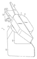
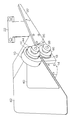
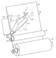
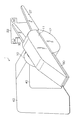
ウエブ切断装置の好ましい形態を図1〜4に基づいて説明する。図1は装置全体を示す平面図、図2はウエブ切断装置の要部拡大図、図3はウエブ切断装置のケーシングを省略した斜視図、図4はロータリーカッタの要部拡大図である。 A preferred embodiment of the web cutting device will be described with reference to FIGS. 1 is a plan view showing the entire apparatus, FIG. 2 is an enlarged view of a main part of the web cutting apparatus, FIG. 3 is a perspective view in which a casing of the web cutting apparatus is omitted, and FIG. 4 is an enlarged view of the main part of the rotary cutter.
ウエブ切断システム100は、ウエブ切断装置1と、ウエブ切断装置1をウエブWの搬送方向(矢印B方向)に対して略直角のウエブWの幅方向(矢印Aの方向)に移動させるための走行装置24を備える。走行装置24は、支持フレーム28と、支持フレーム28に設けられた一対のガイドレール30,30と、一対のガイドレール30,30に移動可能に支持される走行台26とを備える。走行台26はベルト34に連結板33を介して固定される。ベルト34はプーリ32に巻き回される。図示しないプーリ駆動モータによってベルト34が往復移動される。走行装置24の支持フレーム28にラック54が固定される。ウエブ切断装置1は、ホルダ22を介して走行装置24を構成する走行台26に連結される。走行台26を一対のガイドレール30,30に沿って移動させることにより、ウエブ切断装置1を、ウエブWの幅方向に移動させることができる。
Web cutting systems 1 00, the web cutting device 1, for moving in the width direction of the web W substantially perpendicular (the direction of arrow A) with respect to the web cutting device 1 the web W conveying direction (arrow B direction) The
図2、図3に示すように、ウエブ切断装置1は、上部ケーシング10,11と、下部ケーシング12,14を備えている。上部ケーシング10,11と、下部ケーシング12,14との間にはウエブWの厚みより大きい隙間が設けられている。さらに、上部ケーシング10には上部ガイド板40が設けられ、下部ケーシング14には下部ガイド板42が設けられている。上部ガイド板40と下部ガイド板42との間にはウエブWの厚みより大きい隙間が設けられている。
As shown in FIGS. 2 and 3, the web cutting device 1 includes
ウエブ切断装置1の上部ケーシング10,11と、下部ケーシング12,14の内部には上刃と下刃とで構成される一対のロータリーカッタ16,18が設けられている。一対のロータリーカッタ16,18は回転軸36,38を介して上部ケーシング10,11、及び下部ケーシング12,14内に支持される。一対のロータリーカッタ16,18は、ウエブWを挟んで上下にオーバラップ状態で隣接して配置される。一対のロータリーカッタ16,18をほぼ接触する状態でオーバラップさせることでウエブWが切断される。ウエブWが切断される場所が切断点となる。切断手段の一例として、本実施の形態では一対のロータリーカッタ16,18を示したが、これに限定されない。一対のロータリーカッタ16,18に代えて、例えば、レーザー等を使用することができる。なお、上述したように、切断手段はレーザー等であってもよいが、以下はロータリーカッタで説明する。
Inside the
ロータリーカッタ16,18の一方の側には一対のニップローラ44,46が配置されている。図4に示すように、ロータリーカッタ16,18の他方の側には一対のニップローラ48,50が配置されている。ロータリーカッタ16,18の両側に一対のニップローラ44,46と一対のニップローラ48,50とが配置される。
A pair of nip
一対のニップローラ44,46と一対のニップローラ48,50とが回転軸36,38により支持されている。一対のニップローラ44,46と一対のニップローラ48,50とが、ロータリーカッタ16,18に対してウエブWの上流部分とウエブWの下流部分とをウエブWを厚み方向で挟持する。ウエブWを厚み方向で挟持するとは、ウエブWを両面から所定の加圧力で挟み込むこと意味する。ウエブWを両面から挟み込む位置が挟持点となる。一対のニップローラ44,46、及び一対のニップローラ48,50は、ウエブWの種類に応じて、金属、ゴム、プラスチツク等の材料により構成される。
A pair of nip
ここで、ウエブWとは、長手方向に連続する帯状の支持体を意味する。ウエブWは、TAC(トリアセチルセルロース)、PET(ポリエチレンテレフタレート)等の樹脂、アルミニウム、銅等の金属で構成される。ウエブWは80μm以下の厚さを有することが好ましい。ウエブWの厚さが小さい場合、破断頻度が増加するので、本実施の形態を適用した場合に、破断頻度を抑制する効果は大きい。ウエブWの厚さに関して、製造されるフィルム製品に応じて適宜選択することができる。また、ウエブWは、例えば、300〜5000mmの幅を有している。ウエブWの幅に関しても、フィルム製品に応じて適宜選択することができる。 Here, the web W means a belt-like support continuous in the longitudinal direction. The web W is made of a resin such as TAC (triacetyl cellulose) or PET (polyethylene terephthalate), or a metal such as aluminum or copper. The web W preferably has a thickness of 80 μm or less. When the thickness of the web W is small, the breaking frequency increases. Therefore, when this embodiment is applied, the effect of suppressing the breaking frequency is large. The thickness of the web W can be appropriately selected according to the film product to be manufactured. Further, the web W has a width of 300 to 5000 mm, for example. The width of the web W can also be appropriately selected according to the film product.
図1に示すように、ウエブ切断装置1に配置される一対のロータリーカッタ16,18は、ウエブWの搬送方向に対して所定角度θ(ユニット角度)傾けて配置されている。ユニット角度は、例えば、30°以上85°以下の範囲に調整される。
As shown in FIG. 1, the pair of
ウエブ切断装置1は、一対のロータリーカッタ16,18の傾きに沿う前方に、図1、2に示すように、上部ケーシング10,11及び下部ケーシング12,14から上下に傾斜して突設したガイドアーム35,37が設けられている。ウエブ切断装置1がウエブWに向けて一対のガイドレール30,30に沿って移動すると、ガイドアーム35,37が搬送するウエブWを両面から保持し、一対のロータリーカッタ16,18へと案内する。
As shown in FIGS. 1 and 2, the web cutting device 1 is a guide projecting from the
次に、図面を参照してウエブ切断装置1を利用したウエブ切断方法の動作を説明する。図5はウエブ切断装置よる切断前の状態を示している。ウエブWは、所定の間隔で対向する新しい巻芯5とサポートローラ70との間を通過して、旧い巻芯4に巻き取られている。ウエブWを巻芯4に巻き取ることで、張力を付与してウエブWを搬送している。つまり、ウエブWの長手方向に沿う力で引っ張ることでウエブWを移動させている。ウエブ切断装置1は、ウエブWの幅方向の端部から一定の長さ離間して配置されている。ウエブ切断装置1は待機状態となる。
Next, the operation of the web cutting method using the web cutting device 1 will be described with reference to the drawings. FIG. 5 shows a state before cutting by the web cutting device. The web W passes between the
次に、巻芯4により一定の長さのウエブWを巻き取ると、ウエブWの巻き取りを巻芯4から巻芯5に切り替える。図6に示すように、切り替えに先立ち、ウエブWの切断が行われる。ウエブWの切断箇所が到着すると、ウエブ切断装置1を、ウエブWの幅方向(矢印Aの方向)、すなわち切断装置の移動方向に沿って移動させる。切断装置の移動方向AとウエブWの搬送方向Bとの成す角度は略直角である。ウエブWの搬送方向BとはウエブWの進行する方向を意味する。ウエブWの幅方向とは、ウエブWの一端部から他端部に横切る方向を意味する。なお、本出願において「上流」、「下流」の語は、ウエブWの搬送方向に対して用いられる。ある基準に対してウエブの搬送方向側に位置する場合を「下流」、ウエブの搬送方向と反対側に位置する場合を「上流」と定義される。
Next, when the web W having a certain length is wound by the winding
ウエブ切断装置1に組み込まれている一対のロータリーカッタ16,18は、ウエブ切断装置1のウエブWの幅方向への移動に伴い、ウエブWの幅方向にウエブWを切断し始める。ウエブ切断装置1がウエブWの幅方向へ移動するので、一対のロータリーカッタ16,18による切断点もウエブWの幅方向に移動する。
The pair of
ウエブWは、ウエブ切断装置1の移動方向AとウエブWの搬送方向Bとの合成ベクトルの方向に沿って、斜め方向に切断される。この合成ベクトルの方向が、一対のロータリーカッタ16,18による切断点のウエブW上での移動方向となる。切断点のウエブW上での移動方向(矢印Cの方向)は、ロータリーカッタ16,18のユニット角度の方向と略一致することが好ましい。
The web W is cut in an oblique direction along the direction of the combined vector of the moving direction A of the web cutting device 1 and the conveying direction B of the web W. The direction of this combined vector is the moving direction on the web W of the cutting point by the pair of
ウエブ切断装置1でウエブWを切断することにより、切断点のウエブW上での移動方向を基準にウエブWは上流ウエブW1と下流ウエブW2とに分離される。下流ウエブW2は、引き続き巻芯4に巻き取られて、フィルムロールとなる。ウエブ切断装置1が移動し、ウエブWの切断を開始すると、上部ガイド板40と下部ガイド板42の後端が巻芯5のほぼ真下に位置する。上流ウエブW1の切断端部は不安定な挙動を起こすことなく、巻芯5に導かれる。サポートローラ70は上昇して巻芯5に接する。切断された上流ウエブW1は巻芯5の外周面の貼着剤により貼り付けられ巻芯5に巻取られる。
By cutting the web W with the web cutting device 1, the web W is separated into the upstream web W1 and the downstream web W2 based on the moving direction of the cutting point on the web W. The downstream web W2 is continuously wound around the
図7,8は、本実施の形態の原理を説明するための概略平面図である。図7に示すように、本実施の形態では一対のロータリーカッタ16,18による切断点CPでウエブWが切断される。切断点CPの上流では、一対のニップローラ48,50によりウエブWが厚み方向で挟持され、挟持点NP1がウエブWの上に存在している。また、切断点CPの下流では、一対のニップローラ44,46によりウエブWが厚み方向で挟持され、挟持点NP2がウエブWの上に存在している。
7 and 8 are schematic plan views for explaining the principle of the present embodiment. As shown in FIG. 7, in this embodiment, the web W is cut at a cutting point CP by a pair of
さらに、切断点CPがウエブWの幅方向に移動すると、挟持点NP1、NP2も切断点CPの移動に同期して移動する。切断点CPと挟持点NP1、NP2との位置関係が維持される。 Furthermore, when the cutting point CP moves in the width direction of the web W, the clamping points NP1 and NP2 also move in synchronization with the movement of the cutting point CP. The positional relationship between the cutting point CP and the sandwiching points NP1 and NP2 is maintained.
切断点CPがウエブWの幅方向にさらに移動すれば、ウエブWも巻芯4からの張力が付与されているのでさらに搬送され、切断された上流ウエブW1の先端が巻芯5に到達し、上流ウエブW1の先端を巻芯5に貼り付けられる。上流ウエブW1が巻芯5に巻き取とられる。この巻取りにより、上流ウエブW1に張力が付与され、上流ウエブW1が搬送される。ウエブWが完全に切断され、上流ウエブW1が巻芯5に巻き取られる状態になると、上流ウエブW1はウエブWと見なされる。
If the cutting point CP further moves in the width direction of the web W, the web W is also conveyed because the tension from the
切断点CPと挟持点NP1、NP2とは、同一面上に配置されている。ここでいう「同一面」とは、完全に同一な面のみならず、実質的に同一な面も含む。すなわち、切断点CPと挟持点NP1、NP2とを含む仮想的な平面又は略平面が構成されればよい。 The cutting point CP and the sandwiching points NP1 and NP2 are arranged on the same plane. The “same surface” here includes not only completely the same surface but also substantially the same surface. That is, a virtual plane or a substantially plane including the cutting point CP and the sandwiching points NP1 and NP2 may be configured.
切断点CPと挟持点NP1、NP2とが上記の位置関係で配置されている。ウエブWの搬送やウエブWの切断に伴う張力がウエブWに作用していても、挟持点NP1、NP2が切断点CPに張力が作用するのを遮断する。切断点CPのウエブW上の移動方向と、ウエブの実際の切断方向を一致させることができる。ここでの「一致」は完全に一致する場合だけでなく、切断点CPのウエブW上の移動方向に対してウエブの実際の切断方向が±5°の角度以内であれば良い。一方で、ウエブの実際の切断方向が上記の角度大きい場合、いわゆるウエブWが破断したと判断される。 The cutting point CP and the clamping points NP1 and NP2 are arranged in the above positional relationship. Even if the tension accompanying the conveyance of the web W or the cutting of the web W acts on the web W, the clamping points NP1 and NP2 block the tension from acting on the cutting point CP. The moving direction of the cutting point CP on the web W can coincide with the actual cutting direction of the web. Here, “matching” is not limited to the case where they completely match, but the actual cutting direction of the web may be within an angle of ± 5 ° with respect to the moving direction of the cutting point CP on the web W. On the other hand, when the actual cutting direction of the web is larger than the above angle, it is determined that the so-called web W is broken.
さらに、本実施の形態においては、ウエブWを上流ウエブW1と下流ウエブW2とに切断した後、つまり、切断点CPのウエブW上での移動方向の後ろ側の位置において、上流ウエブW1及び/又は下流ウエブがウエブWに対して垂直方向へ移動するのが規制される。ここで「上流ウエブW1又は/及び下流ウエブW2がウエブWに対して垂直方向へ移動」とは、上流ウエブW1又は/及び下流ウエブW2に何らかの外力(重力等)が作用し、ウエブWと同一平面を構成しない方向へ移動することをいう。「規制」するとは、何もしない場合に比べて垂直方向の移動距離を小さくすることをいう。垂直方向の移動距離は20mm以下とするのが好ましく、10mm以下とすることがより好ましく、理想的には移動距離0mmである。 Further, in the present embodiment, after the web W is cut into the upstream web W1 and the downstream web W2, that is, at the position behind the cutting point CP in the movement direction on the web W, the upstream web W1 and / or Alternatively, the movement of the downstream web in the direction perpendicular to the web W is restricted. Here, “the upstream web W1 and / or the downstream web W2 moves in the direction perpendicular to the web W” means that some external force (gravity, etc.) acts on the upstream web W1 and / or the downstream web W2 and is the same as the web W. It means moving in a direction that does not constitute a plane. “Regulation” means to make the moving distance in the vertical direction smaller than when nothing is done. The moving distance in the vertical direction is preferably 20 mm or less, more preferably 10 mm or less, and ideally the moving distance is 0 mm.
切断点CPのウエブW上での移動方向の後ろ側とは、切断点を基準に、切断点のウエブW上での移動方向と反対側を意味する。つまり、切断点の移動方向の後ろ側とは、ウエブWが上流ウエブW1と下流ウエブW2とに分離されている側をいう。切断点CPのウエブW上での移動方向の後ろ側は図7,8において矢印Dで示す側を意味する。 The rear side of the moving direction of the cutting point CP on the web W means the side opposite to the moving direction of the cutting point on the web W with reference to the cutting point. That is, the rear side in the moving direction of the cutting point refers to the side where the web W is separated into the upstream web W1 and the downstream web W2. The rear side of the movement direction of the cutting point CP on the web W means the side indicated by the arrow D in FIGS.
上流ウエブW1及び/又は下流ウエブW2がウエブWに対して垂直方向へ移動するのが規制されるので、上流ウエブW1と下流ウエブW2との間で切断点CPを中心とする開きが生じるのを抑制できる。図9において、ウエブ切断装置1の下部ケーシング12が、切断点CPのウエブW上での移動方向の後ろ側に切断点CPから伸びている。ウエブ切断装置1において、上流ウエブW1と下流ウエブW2との間で切断点CPを中心とする開きが生じるのが抑制されているので、ウエブWに破断が生じないと考えられる。ウエブ切断装置1では下部ケーシング12が移動規制機構のガイド部材と機能している。図10に示すように、移動規制機構として下部ケーシング12とは別に板状の部材80でガイド部材を構成することもできる。上流ウエブW1及び/又は下流ウエブW2がウエブWに対して垂直方向へ移動するのが規制される限り、大きさ形状を適宜選択することができる。
Since the upstream web W1 and / or the downstream web W2 are restricted from moving in the direction perpendicular to the web W, an opening around the cutting point CP occurs between the upstream web W1 and the downstream web W2. Can be suppressed. In FIG. 9, the
図11に示すように、移動規制機構としてガイド部材に代えてノズル90を設けることができる。ノズル90からエアを吹き付けする及び/又はエアを吸引することで上流ウエブ及び/又は下流ウエブが移動することを規制することができる。板状の部材80とノズル90とを同時に使用することができる。
As shown in FIG. 11, a nozzle 90 can be provided as a movement restricting mechanism instead of the guide member. Upstream web and / or by sucking the to and / or air blowing the air from the nozzle 90 can be restricted that the downstream web moves. The plate-
移動規制機構としてガイド部材を使用する場合、ウエブ切断装置1に容易に取付けることができる。移動規制機構としてエアを吹き付けするノズル及び/又はエアを吸引するノズルを使用する場合、外力の値に応じて、規制力を調整することができる。 When a guide member is used as the movement restricting mechanism, it can be easily attached to the web cutting device 1. When a nozzle that blows air and / or a nozzle that sucks air is used as the movement restriction mechanism, the restriction force can be adjusted according to the value of the external force.
ここで、「上流ウエブW1と下流ウエブW2との間で切断点CPを中心とする開き」とは、図10に示すように、切断点CPのウエブW上で移動方向の後ろ側で、切断点CPの直後から上流ウエブW1及び/又は下流ウエブW2との間で隙間ができる状態をいう。 Here, “the opening around the cutting point CP between the upstream web W1 and the downstream web W2” means that cutting is performed on the web W at the cutting point CP on the rear side in the moving direction, as shown in FIG. A state where a gap is formed between the upstream web W1 and / or the downstream web W2 immediately after the point CP.
上流ウエブW1と下流ウエブW2との間での開きは、ウエブWの幅方向の全域で防止する必要はなく、切断点CPからウエブW上での移動方向の後ろ側の距離Lの間で開きが防止できればよい。つまり、切断点CPを中心とする開きが生じなければ良い。距離Lは、ウエブの規制距離を指す。ガイド板を用いる場合はガイド板の長さ、吹き付け/吸引エアノズルを用いる場合はウエブへのエア吹き付け/吸引長さを指す。距離Lは、切断点CPのウエブW上での移動方向とウエブWの切断方向を一致させてウエブWに破断が生じない範囲で選択すれば良い。距離Lを長くとるほど破断を防止できる方向なので、破断が起きる場合は距離をより長くとれば良い。距離Lは5mm以上とするのが好ましく、10mm以上とすることがより好ましく、50mm以上とすることがより好ましい。 The opening between the upstream web W1 and the downstream web W2 does not need to be prevented in the entire width direction of the web W, and is opened between the distance L on the rear side in the moving direction on the web W from the cutting point CP. If it can prevent. That is, it is sufficient that the opening around the cutting point CP does not occur. The distance L indicates the restricted distance of the web. When a guide plate is used, it indicates the length of the guide plate, and when a blowing / suction air nozzle is used, it indicates the length of air blowing / suction to the web. The distance L may be selected within a range in which the movement direction of the cutting point CP on the web W and the cutting direction of the web W coincide with each other and the web W does not break. Since the longer the distance L is, the more the fracture can be prevented, the longer the distance may be taken when the fracture occurs. The distance L is preferably 5 mm or more, more preferably 10 mm or more, and more preferably 50 mm or more.
上流ウエブW1又は/及び下流ウエブW2がウエブWに対して垂直方向へ移動することを規制する場合、切断点CPのウエブW上での移動方向の後ろ側で上流ウエブW1又は/及び下流ウエブW2を、切断点における挟持点の加圧力より弱い力で規制することが好ましい。つまり、垂直方向への移動を規制する際に、挟持しないことを含む。切断点における挟持点の加圧力より弱い力で規制することにより、切断点の移動方向の前後でのウエブWの送り速度を厳密に合致させる必要がなくなるからである。さらに、ウエブWの破断頻度が増加するのを抑制することができる。 When restricting the movement of the upstream web W1 and / or the downstream web W2 in the direction perpendicular to the web W, the upstream web W1 and / or the downstream web W2 is located behind the cutting point CP in the movement direction on the web W. Is preferably regulated with a force weaker than the pressing force at the clamping point at the cutting point. In other words, this includes not clamping when restricting movement in the vertical direction. This is because it is not necessary to strictly match the feeding speed of the web W before and after the cutting point in the moving direction by restricting with a force weaker than the pressing force of the clamping point at the cutting point. Furthermore, it is possible to suppress an increase in the breaking frequency of the web W.
以下、本発明の実施例を挙げ、本発明を、より詳細に説明する。但し、本発明は、これらの実施例に何ら限定されるものではない。 Hereinafter, the present invention will be described in more detail with reference to examples of the present invention. However, the present invention is not limited to these examples.
セルローストリアセテートフィルム(厚さ:40μm、幅:1500mm)を100Nの張力(全幅)、50m/分の速度で搬送した。搬送中にセルローストリアセテートフィルムを切断し、空の巻芯に巻き取った。移動規制機構を備えるウエブ切断装置と移動規制機構を備えないウエブ切断装置とを使用した。本実施例では移動規制機構として下部ケーシングをガイド部材として使用した。移動規制機構を備えるウエブ切断装置においては、ガイド部材の長さ(距離L)を変更した。 A cellulose triacetate film (thickness: 40 μm, width: 1500 mm) was conveyed at a tension of 100 N (full width) and a speed of 50 m / min. During the conveyance, the cellulose triacetate film was cut and wound around an empty core. A web cutting device having a movement restricting mechanism and a web cutting device not having a movement restricting mechanism were used. In this embodiment, the lower casing is used as a guide member as a movement restricting mechanism. In the web cutting device provided with the movement restricting mechanism, the length (distance L) of the guide member is changed.
ウエブの切断後、ウエブの破断の個数をカウントした。破断個数は、破断長さを定規で測定し、長さが1mm以上のものを1つとカウントした。破断の個数が1以下であれば製品とした優れたレベルでA評価となり、破断の個数が2以上6以下であれば製品として使用可能なレベルでB評価となり、破断の個数が7以上であると製品として使用できないレベルでありC評価となる。表1は、ウエブ切断の条件と評価結果を示す。この表1から移動規制機構を有する場合、破断頻度が抑制されることが理解できる。また、ガイド部材の距離Lが長い場合、距離Lが短い場合に比較して、破断抑制効果が大きいことが理解できる。 After the web was cut, the number of web breaks was counted. The number of breaks was determined by measuring the break length with a ruler and counting one with a length of 1 mm or more. If the number of breaks is 1 or less, the product is rated as A with an excellent level, and if the number of breaks is 2 or more and 6 or less, it is evaluated as B at a level usable as a product, and the number of breaks is 7 or more. It is a level that cannot be used as a product and is rated as C. Table 1 shows web cutting conditions and evaluation results. It can be understood from Table 1 that when the movement restricting mechanism is provided, the breaking frequency is suppressed. Further, it can be understood that when the distance L of the guide member is long, the effect of suppressing breakage is greater than when the distance L is short.

1:ウエブ切断装置、16,18:ロータリーカッタ、24:走行装置、44,46,48,50:ニップローラ、10,11:上部ケーシング、12,14:下部ケーシング 1: Web cutting device, 16, 18: Rotary cutter, 24: Traveling device, 44, 46, 48, 50: Nip roller, 10, 11 : Upper casing, 12, 14: Lower casing
Claims (9)
切断手段による切断点を前記ウエブの幅方向に移動させながら、搬送される前記ウエブを上流ウエブと下流ウエブとに切断する工程と、を備え、
前記ウエブを切断する工程において、前記切断点に対して前記ウエブの上流部分と前記ウエブの下流部分とを前記ウエブの厚み方向で挟持し、かつ前記切断点と前記上流部分及び前記下流部分の2つの挟持点とを同一面上に位置させ、
かつ前記切断点の前記ウエブ上での移動方向の後ろ側で、切断された前記上流ウエブ及び前記下流ウエブが前記ウエブに対して垂直方向へ移動することを規制するウエブ切断方法。 Applying tension and transporting the web;
Cutting the web being conveyed into an upstream web and a downstream web while moving a cutting point by a cutting means in the width direction of the web, and
In the step of cutting the web, the upstream portion of the web and the downstream portion of the web are sandwiched with respect to the cutting point in the thickness direction of the web, and the cutting point, the upstream portion, and the downstream portion Position two clamping points on the same plane,
And wherein behind a moving direction on the web of the cutting point, web cutting wherein said upstream web及beauty before Symbol downstream web which is cut to regulate the moving direction perpendicular to the web.
切断手段と、
前記切断手段による切断点の両側に配置された2つの一対のニップローラであって、前記2つの一対のニップローラは前記切断点に対して前記ウエブの上流部分と前記ウエブの下流部分とを前記ウエブの厚み方向でそれぞれ挟持し、前記切断点と前記上流部分及び前記下流部分の2つの挟持点とを同一面上に位置させている一対のニップローラと、
前記切断点の前記ウエブ上での移動方向の後ろ側に配置され、前記上流ウエブ及び前記下流ウエブが前記ウエブに対して垂直方向へ移動することを規制する移動規制機構と、
を備えるウエブ切断装置。 A web cutting device for cutting a conveyed web and separating the web into an upstream web and a downstream web,
Cutting means;
Two pairs of nip rollers disposed on both sides of a cutting point by the cutting means, wherein the two pairs of nip rollers connect an upstream portion of the web and a downstream portion of the web with respect to the cutting point. A pair of nip rollers that are sandwiched in the thickness direction, and the cutting point and the two sandwiching points of the upstream portion and the downstream portion are located on the same plane;
Wherein disposed on the rear side in the moving direction on the web of the cutting point, a movement restriction mechanism which the upstream web及beauty before Symbol downstream web to restrict the moving direction perpendicular to the web,
A web cutting device comprising:
Priority Applications (4)
| Application Number | Priority Date | Filing Date | Title |
|---|---|---|---|
| JP2013172645A JP5833065B2 (en) | 2013-08-22 | 2013-08-22 | Web cutting method and web cutting device |
| CN201410412490.6A CN104418136B (en) | 2013-08-22 | 2014-08-20 | Net cutting-off method and net shearing device |
| KR1020140108271A KR102171673B1 (en) | 2013-08-22 | 2014-08-20 | Method of cutting web and apparatus of cutting web |
| TW103128725A TWI621488B (en) | 2013-08-22 | 2014-08-21 | Method of cutting web and apparatus of cutting web |
Applications Claiming Priority (1)
| Application Number | Priority Date | Filing Date | Title |
|---|---|---|---|
| JP2013172645A JP5833065B2 (en) | 2013-08-22 | 2013-08-22 | Web cutting method and web cutting device |
Publications (3)
| Publication Number | Publication Date |
|---|---|
| JP2015039747A JP2015039747A (en) | 2015-03-02 |
| JP2015039747A5 JP2015039747A5 (en) | 2015-04-09 |
| JP5833065B2 true JP5833065B2 (en) | 2015-12-16 |
Family
ID=52694202
Family Applications (1)
| Application Number | Title | Priority Date | Filing Date |
|---|---|---|---|
| JP2013172645A Active JP5833065B2 (en) | 2013-08-22 | 2013-08-22 | Web cutting method and web cutting device |
Country Status (4)
| Country | Link |
|---|---|
| JP (1) | JP5833065B2 (en) |
| KR (1) | KR102171673B1 (en) |
| CN (1) | CN104418136B (en) |
| TW (1) | TWI621488B (en) |
Families Citing this family (4)
| Publication number | Priority date | Publication date | Assignee | Title |
|---|---|---|---|---|
| JP6448569B2 (en) * | 2016-03-03 | 2019-01-09 | 富士フイルム株式会社 | Web cutting method and web cutting device |
| CN110728803B (en) * | 2019-11-04 | 2021-10-08 | 深圳市点易达科技有限公司 | Integrative cabinet of unmanned commodity circulation in green city |
| CN112125048B (en) * | 2020-09-17 | 2022-04-15 | 青岛齐林智信自控技术有限公司 | Method and equipment for increasing winding length of casing |
| DE102021119893A1 (en) * | 2021-07-30 | 2023-02-02 | Windmöller & Hölscher Kg | Winder for winding a web of material |
Family Cites Families (11)
| Publication number | Priority date | Publication date | Assignee | Title |
|---|---|---|---|---|
| GB262975A (en) * | 1926-01-22 | 1926-12-23 | Walter Everett Molins | Improvements in or relating to mechanism for severing a moving web into lengths |
| US1782674A (en) * | 1928-06-30 | 1930-11-25 | Hoe & Co R | Web-cutting mechanism |
| ES400106A1 (en) * | 1971-02-27 | 1975-06-16 | Alberto | Automatic machine for forming rolls of piece-fabrics having a pre-established length and discarding of defective fabric |
| JPS61146494A (en) * | 1984-12-18 | 1986-07-04 | 富士写真フイルム株式会社 | Method and device for cutting web |
| JPS62140797A (en) * | 1985-12-13 | 1987-06-24 | 帝人製機株式会社 | Method and device for cutting thin band body |
| JPH11165922A (en) * | 1997-11-28 | 1999-06-22 | Kawakami Sangyo Kk | Rewinding device and method for sheet material |
| JP3041302B1 (en) * | 1999-05-25 | 2000-05-15 | 明産株式会社 | Overlap assist device in sheet cutting device |
| DE102004016217A1 (en) * | 2004-04-01 | 2005-10-20 | Brueckner Maschbau | Method and device for processing a film web |
| EP1741525A1 (en) * | 2005-07-06 | 2007-01-10 | Trumpf Werkzeugmaschinen GmbH + Co. KG | Device for supporting plate materials |
| JP5883660B2 (en) * | 2012-01-24 | 2016-03-15 | 小倉工業株式会社 | Web winding device and web winding method using this device |
| JP2019038657A (en) * | 2017-08-24 | 2019-03-14 | 株式会社ヒラノテクシード | Suction device and web connection device |
-
2013
- 2013-08-22 JP JP2013172645A patent/JP5833065B2/en active Active
-
2014
- 2014-08-20 CN CN201410412490.6A patent/CN104418136B/en active Active
- 2014-08-20 KR KR1020140108271A patent/KR102171673B1/en active IP Right Grant
- 2014-08-21 TW TW103128725A patent/TWI621488B/en active
Also Published As
| Publication number | Publication date |
|---|---|
| CN104418136B (en) | 2017-10-10 |
| JP2015039747A (en) | 2015-03-02 |
| KR102171673B1 (en) | 2020-10-29 |
| KR20150022696A (en) | 2015-03-04 |
| TW201515744A (en) | 2015-05-01 |
| TWI621488B (en) | 2018-04-21 |
| CN104418136A (en) | 2015-03-18 |
Similar Documents
| Publication | Publication Date | Title |
|---|---|---|
| JP5833065B2 (en) | Web cutting method and web cutting device | |
| TWI820156B (en) | How to make glass rolls | |
| KR20150083112A (en) | Method of processing a glass ribbon | |
| JP2008200788A (en) | Optical film cutting device and optical film manufacturing method | |
| CN104936908B (en) | The method that continuous glass tape is processed | |
| US20160137543A1 (en) | Apparatus and method for processing lengths of flexible glass | |
| JP2012166893A5 (en) | ||
| US20170369356A1 (en) | Methods and apparatus for fabricating respective sections from a glass web | |
| JP6322591B2 (en) | Film edge cutting method, film edge cutting apparatus, and optical film manufacturing method | |
| JP2015039747A5 (en) | ||
| JP5466056B2 (en) | Solution casting method | |
| JP5480315B2 (en) | Web cutting method and web cutting device | |
| JP6087418B1 (en) | Sheet winding device | |
| JP6324913B2 (en) | Web winding method and web winding device | |
| JP6448569B2 (en) | Web cutting method and web cutting device | |
| JP2013173192A5 (en) | ||
| JP5718504B1 (en) | Folding device | |
| CN220465974U (en) | Packaging attaching device | |
| JP2013198968A (en) | Trimming device | |
| WO2013018440A1 (en) | Device and method for supplying shape retaining material | |
| JP2009220964A (en) | Web conveying device and web splicing method | |
| JP6394664B2 (en) | Electrode plate pressing device and electrode plate manufacturing method | |
| JP2015003368A (en) | Trimming apparatus, and manufacturing method of optical film | |
| JPH08141823A (en) | Trimming device | |
| JP2015189147A5 (en) |
Legal Events
| Date | Code | Title | Description |
|---|---|---|---|
| A621 | Written request for application examination |
Free format text: JAPANESE INTERMEDIATE CODE: A621 Effective date: 20141210 |
|
| A521 | Request for written amendment filed |
Free format text: JAPANESE INTERMEDIATE CODE: A523 Effective date: 20150113 |
|
| A977 | Report on retrieval |
Free format text: JAPANESE INTERMEDIATE CODE: A971007 Effective date: 20150604 |
|
| A131 | Notification of reasons for refusal |
Free format text: JAPANESE INTERMEDIATE CODE: A131 Effective date: 20150608 |
|
| A521 | Request for written amendment filed |
Free format text: JAPANESE INTERMEDIATE CODE: A523 Effective date: 20150713 |
|
| TRDD | Decision of grant or rejection written | ||
| A01 | Written decision to grant a patent or to grant a registration (utility model) |
Free format text: JAPANESE INTERMEDIATE CODE: A01 Effective date: 20151009 |
|
| A61 | First payment of annual fees (during grant procedure) |
Free format text: JAPANESE INTERMEDIATE CODE: A61 Effective date: 20151028 |
|
| R150 | Certificate of patent or registration of utility model |
Ref document number: 5833065 Country of ref document: JP Free format text: JAPANESE INTERMEDIATE CODE: R150 |
|
| R250 | Receipt of annual fees |
Free format text: JAPANESE INTERMEDIATE CODE: R250 |
|
| R250 | Receipt of annual fees |
Free format text: JAPANESE INTERMEDIATE CODE: R250 |
|
| R250 | Receipt of annual fees |
Free format text: JAPANESE INTERMEDIATE CODE: R250 |
|
| R250 | Receipt of annual fees |
Free format text: JAPANESE INTERMEDIATE CODE: R250 |
|
| R250 | Receipt of annual fees |
Free format text: JAPANESE INTERMEDIATE CODE: R250 |
|
| R250 | Receipt of annual fees |
Free format text: JAPANESE INTERMEDIATE CODE: R250 |