JP4786355B2 - Power supply voltage control method for vehicles - Google Patents
Power supply voltage control method for vehicles Download PDFInfo
- Publication number
- JP4786355B2 JP4786355B2 JP2006022303A JP2006022303A JP4786355B2 JP 4786355 B2 JP4786355 B2 JP 4786355B2 JP 2006022303 A JP2006022303 A JP 2006022303A JP 2006022303 A JP2006022303 A JP 2006022303A JP 4786355 B2 JP4786355 B2 JP 4786355B2
- Authority
- JP
- Japan
- Prior art keywords
- current
- voltage
- battery
- control
- regression line
- Prior art date
- Legal status (The legal status is an assumption and is not a legal conclusion. Google has not performed a legal analysis and makes no representation as to the accuracy of the status listed.)
- Expired - Fee Related
Links
Images

Classifications
-
- H—ELECTRICITY
- H01—ELECTRIC ELEMENTS
- H01M—PROCESSES OR MEANS, e.g. BATTERIES, FOR THE DIRECT CONVERSION OF CHEMICAL ENERGY INTO ELECTRICAL ENERGY
- H01M10/00—Secondary cells; Manufacture thereof
- H01M10/42—Methods or arrangements for servicing or maintenance of secondary cells or secondary half-cells
- H01M10/48—Accumulators combined with arrangements for measuring, testing or indicating the condition of cells, e.g. the level or density of the electrolyte
-
- H—ELECTRICITY
- H02—GENERATION; CONVERSION OR DISTRIBUTION OF ELECTRIC POWER
- H02J—ELECTRIC POWER NETWORKS; CIRCUIT ARRANGEMENTS OR SYSTEMS FOR SUPPLYING OR DISTRIBUTING ELECTRIC POWER; SYSTEMS FOR STORING ELECTRIC ENERGY
- H02J7/00—Circuit arrangements for charging or discharging batteries or for supplying loads from batteries
- H02J7/14—Circuit arrangements for charging or discharging batteries or for supplying loads from batteries for charging batteries from dynamo-electric generators driven at varying speed, e.g. on vehicle
- H02J7/1438—Circuit arrangements for charging or discharging batteries or for supplying loads from batteries for charging batteries from dynamo-electric generators driven at varying speed, e.g. on vehicle in combination with power supplies for loads other than batteries
-
- G—PHYSICS
- G01—MEASURING; TESTING
- G01R—MEASURING ELECTRIC VARIABLES; MEASURING MAGNETIC VARIABLES
- G01R19/00—Arrangements for measuring currents or voltages or for indicating presence or sign thereof
- G01R19/165—Indicating that current or voltage is either above or below a predetermined value or within or outside a predetermined range of values
- G01R19/16533—Indicating that current or voltage is either above or below a predetermined value or within or outside a predetermined range of values characterised by the application
- G01R19/16538—Indicating that current or voltage is either above or below a predetermined value or within or outside a predetermined range of values characterised by the application in AC or DC supplies
- G01R19/16542—Indicating that current or voltage is either above or below a predetermined value or within or outside a predetermined range of values characterised by the application in AC or DC supplies for batteries
-
- G—PHYSICS
- G01—MEASURING; TESTING
- G01R—MEASURING ELECTRIC VARIABLES; MEASURING MAGNETIC VARIABLES
- G01R31/00—Arrangements for testing electric properties; Arrangements for locating electric faults; Arrangements for electrical testing characterised by what is being tested not provided for elsewhere
- G01R31/36—Arrangements for testing, measuring or monitoring the electrical condition of accumulators or electric batteries, e.g. capacity or state of charge [SoC]
- G01R31/3644—Constructional arrangements
- G01R31/3648—Constructional arrangements comprising digital calculation means, e.g. for performing an algorithm
-
- G—PHYSICS
- G01—MEASURING; TESTING
- G01R—MEASURING ELECTRIC VARIABLES; MEASURING MAGNETIC VARIABLES
- G01R31/00—Arrangements for testing electric properties; Arrangements for locating electric faults; Arrangements for electrical testing characterised by what is being tested not provided for elsewhere
- G01R31/36—Arrangements for testing, measuring or monitoring the electrical condition of accumulators or electric batteries, e.g. capacity or state of charge [SoC]
- G01R31/382—Arrangements for monitoring battery or accumulator variables, e.g. SoC
- G01R31/3842—Arrangements for monitoring battery or accumulator variables, e.g. SoC combining voltage and current measurements
-
- H—ELECTRICITY
- H02—GENERATION; CONVERSION OR DISTRIBUTION OF ELECTRIC POWER
- H02J—ELECTRIC POWER NETWORKS; CIRCUIT ARRANGEMENTS OR SYSTEMS FOR SUPPLYING OR DISTRIBUTING ELECTRIC POWER; SYSTEMS FOR STORING ELECTRIC ENERGY
- H02J7/00—Circuit arrangements for charging or discharging batteries or for supplying loads from batteries
- H02J7/14—Circuit arrangements for charging or discharging batteries or for supplying loads from batteries for charging batteries from dynamo-electric generators driven at varying speed, e.g. on vehicle
- H02J7/16—Regulation of the charging current or voltage by variation of field
- H02J7/24—Regulation of the charging current or voltage by variation of field using discharge tubes or semiconductor devices
-
- H—ELECTRICITY
- H02—GENERATION; CONVERSION OR DISTRIBUTION OF ELECTRIC POWER
- H02J—ELECTRIC POWER NETWORKS; CIRCUIT ARRANGEMENTS OR SYSTEMS FOR SUPPLYING OR DISTRIBUTING ELECTRIC POWER; SYSTEMS FOR STORING ELECTRIC ENERGY
- H02J7/00—Circuit arrangements for charging or discharging batteries or for supplying loads from batteries
- H02J7/80—Circuit arrangements for charging or discharging batteries or for supplying loads from batteries including monitoring or indicating arrangements
- H02J7/82—Control of state of charge [SOC]
-
- Y—GENERAL TAGGING OF NEW TECHNOLOGICAL DEVELOPMENTS; GENERAL TAGGING OF CROSS-SECTIONAL TECHNOLOGIES SPANNING OVER SEVERAL SECTIONS OF THE IPC; TECHNICAL SUBJECTS COVERED BY FORMER USPC CROSS-REFERENCE ART COLLECTIONS [XRACs] AND DIGESTS
- Y02—TECHNOLOGIES OR APPLICATIONS FOR MITIGATION OR ADAPTATION AGAINST CLIMATE CHANGE
- Y02E—REDUCTION OF GREENHOUSE GAS [GHG] EMISSIONS, RELATED TO ENERGY GENERATION, TRANSMISSION OR DISTRIBUTION
- Y02E60/00—Enabling technologies; Technologies with a potential or indirect contribution to GHG emissions mitigation
- Y02E60/10—Energy storage using batteries
-
- Y—GENERAL TAGGING OF NEW TECHNOLOGICAL DEVELOPMENTS; GENERAL TAGGING OF CROSS-SECTIONAL TECHNOLOGIES SPANNING OVER SEVERAL SECTIONS OF THE IPC; TECHNICAL SUBJECTS COVERED BY FORMER USPC CROSS-REFERENCE ART COLLECTIONS [XRACs] AND DIGESTS
- Y02—TECHNOLOGIES OR APPLICATIONS FOR MITIGATION OR ADAPTATION AGAINST CLIMATE CHANGE
- Y02T—CLIMATE CHANGE MITIGATION TECHNOLOGIES RELATED TO TRANSPORTATION
- Y02T10/00—Road transport of goods or passengers
- Y02T10/60—Other road transportation technologies with climate change mitigation effect
- Y02T10/70—Energy storage systems for electromobility, e.g. batteries
Landscapes
- Engineering & Computer Science (AREA)
- Power Engineering (AREA)
- Physics & Mathematics (AREA)
- General Physics & Mathematics (AREA)
- Manufacturing & Machinery (AREA)
- Chemical & Material Sciences (AREA)
- Chemical Kinetics & Catalysis (AREA)
- Electrochemistry (AREA)
- General Chemical & Material Sciences (AREA)
- Secondary Cells (AREA)
- Charge And Discharge Circuits For Batteries Or The Like (AREA)
- Tests Of Electric Status Of Batteries (AREA)
Description
本発明は、バッテリの電源電圧を所定の目標レベルに収束させる車両用電源電圧制御方法に関する。 The present invention relates to a vehicle power supply voltage control method for converging a battery power supply voltage to a predetermined target level .
車両用に用いられるバッテリは容量管理や安全管理の必要性からバッテリの状態を高精度に推定する必要がある。従来、この目的のために、バッテリの電池状態量(たとえば電池の電圧や電流や残存容量や開路電圧や内部抵抗など)を演算するバッテリの状態量演算装置が種々提案乃至実用されている。 A battery used for a vehicle needs to estimate the state of the battery with high accuracy from the necessity of capacity management and safety management. Conventionally, for this purpose, various battery state quantity computing devices for computing battery state quantities (for example, battery voltage, current, remaining capacity, open circuit voltage, internal resistance, etc.) have been proposed or put into practical use.
これらのバッテリの状態量演算装置に共通する構成は、入力パラメータとしてバッテリの多数の電圧・電流ペアを採取し、それに基づいて得た電圧と電流との間の関係を電池状態量推定に利用することである。 The configuration common to these battery state quantity calculation devices collects a large number of battery voltage / current pairs as input parameters, and uses the relationship between the voltage and current obtained based on them to estimate the battery state quantity. That is.
しかし、電池の残存容量状態や温度や劣化状態や分極状態など電圧と電流との間の関係に関与する多くの現象が存在するため、電圧と電流との間の関係は単純な線形関係とはならなかった。 However, since there are many phenomena related to the relationship between voltage and current, such as the remaining capacity state, temperature, deterioration state, and polarization state of the battery, the relationship between voltage and current is a simple linear relationship did not become.
従来用いられていた電圧と電流との間の関係を推定する方式の一つは、多数の電圧・電流ペアを電圧(V)及び電流(I)を二次元空間にプロットして回帰線を創成し、この回帰線を用いて入力電圧値に対応する電流値、もしくは、入力電流値に対応する電圧値を推定する方式(回帰線利用方式)であり、現在広く用いられている。なお、この回帰線の傾斜率は、バッテリの内部抵抗を示す値となる。 One method of estimating the relationship between voltage and current used in the past is to create a regression line by plotting multiple voltage / current pairs in voltage (V) and current (I) in a two-dimensional space. A method of using this regression line to estimate a current value corresponding to an input voltage value or a voltage value corresponding to an input current value (regression line utilization method) is widely used at present. The slope of the regression line is a value indicating the internal resistance of the battery.
その他、サンプリングした多数の電圧・電流ペアやそれ以外の電池状態量(たとえば温度や運転時間など)をニューラルネットワークに投入して、出力パラメータとしての電池状態量(たとえばSOCなど)を推定することも提案されている(特許文献1、2)。
しかし、上記した従来の回帰線利用方式を用いる電池状態量の推定では、多数の電圧・電流ペアの座標点が二次元空間に広く分散するため、求めた回帰線の精度が低いため、この回帰線を用いて得た電池状態量の誤差が非常に大きいことが広く知られていた。 However, in the estimation of the battery state quantity using the above-described conventional regression line utilization method, since the coordinate points of a large number of voltage / current pairs are widely dispersed in the two-dimensional space, the accuracy of the obtained regression line is low. It was widely known that the battery state quantity error obtained using the line was very large.
また、上記したニューラルネット演算方式は従来の回帰線利用方式を用いた電池状態量推定に比べて格段に処理装置及び処理負担が増大するにもかかわらず、まだ満足すべき演算精度を得ることができないというのが実状であった。 In addition, the above-described neural network calculation method can obtain satisfactory calculation accuracy even though the processing device and the processing load are significantly increased as compared with the battery state quantity estimation using the conventional regression line utilization method. The fact was that it was impossible.
次に、車両用電源系について考えると、電源電圧の大きな変動は、負荷動作の不安定やヘッドランプのちらつきやバッテリ寿命の低下など種々の問題が生じる。そこで、負荷状況変化などにもかかわらず電源電圧(バッテリ電圧)を安定化させたいという強い要求がある。従来の車両における電源電圧管理は、検出した電源電圧とその目標電圧との差を0に収束するようにフィードバック制御するのが一般的である。しかし、このフィードバック制御により電源電圧を変更すると、それに応じてバッテリの内部状態が変化するため電源電圧にハンチングが生じたり、遅れたりしてたとえば電気負荷の変動などによる電源電圧の急変に精密に即応して安定化制御を行うことが困難であった。 Next, considering a vehicle power supply system, a large fluctuation in power supply voltage causes various problems such as unstable load operation, flickering of headlamps, and a decrease in battery life. Therefore, there is a strong demand to stabilize the power supply voltage (battery voltage) in spite of changes in load conditions. In conventional power supply voltage management in a vehicle, feedback control is generally performed so that the difference between a detected power supply voltage and its target voltage converges to zero. However, if the power supply voltage is changed by this feedback control, the internal state of the battery changes accordingly, so that hunting occurs or delays in the power supply voltage, so that it can respond quickly and quickly to sudden changes in the power supply voltage due to fluctuations in the electrical load, etc. Therefore, it is difficult to perform stabilization control.
本発明は上記問題点に鑑みなされたものであり、電源電圧の高速高精度の安定制御が可能な車両用電源電圧制御方法を提供することをその発明課題としている。 The present invention has as its invention aims to provide the has been made in view of the problems, the power supply voltage control method for a vehicle capable of stably controlling a high-speed, high-precision of the supply voltage.
上記課題を解決する本発明のバッテリの状態量演算方法は、バッテリ、発電手段及び電気負荷が接続された車両の電源ラインの電圧である電源電圧を所定の目標電圧に制御する車両用電源電圧制御方法において、前記バッテリから検出した複数の電圧・電流ペアに基づいて前記バッテリの電圧と電流との間の回帰線を所定タイミングごとに更新し、前記目標電圧と前記回帰線とから前記バッテリの電流である制御電流の値を算出し、前記バッテリの電流を前記制御電流の値に調整する制御することにより、前記バッテリに接続された回路系に印加する電源電圧を所定の目標レベルに収束させることを特徴としている。 The battery state quantity calculation method of the present invention that solves the above-described problem is a vehicle power supply voltage control that controls a power supply voltage that is a voltage of a power supply line of a vehicle to which a battery, power generation means, and an electric load are connected to a predetermined target voltage. In the method, a regression line between the voltage and current of the battery is updated at predetermined timing based on a plurality of voltage / current pairs detected from the battery, and the current of the battery is calculated from the target voltage and the regression line. The power supply voltage applied to the circuit system connected to the battery is converged to a predetermined target level by calculating the control current value and controlling the battery current to the control current value. It is characterized by.
すなわち、この発明は、走行状況などにより電圧変化が大きい車両用電源系の電源電圧制御を、バッテリの充放電電流を算出した制御電流に制御することにより行う。このようにすれば、電源電圧とその目標電圧との差に応じて発電量を制御する従来の電源電圧フィードバック制御に比較して、制御実施によるバッテリの内部状態の変化を加味して電源電圧を調整できるため、制御レスポンスの改善を図ることができる。 That is, according to the present invention, the power supply voltage control of the vehicle power supply system having a large voltage change depending on the traveling condition or the like is performed by controlling the control current calculated from the charge / discharge current of the battery. In this way, compared with the conventional power supply voltage feedback control that controls the amount of power generation according to the difference between the power supply voltage and its target voltage, the power supply voltage is adjusted by taking into account the change in the internal state of the battery due to control execution. Since it can be adjusted, the control response can be improved.
本発明において、前記バッテリから検出した複数の電圧・電流ペアに基づいて前記バッテリの電圧と電流との間の回帰線を所定の更新タイミングごとに更新し、前記目標電圧と前記回帰線とから前記バッテリの電流である制御電流の値を算出し、前記バッテリの電流を前記制御電流の値に調整する。本発明では、電源電圧の目標値である目標電圧に対応するバッテリの充放電電流値への制御電流の値の変更を、バッテリの電圧と電流との間の関係を示す回帰線を用いて行うため、精度良く電源電圧を目標電圧に収束させることができる。更新タイミングとしては、短期間の間に電流が大きく変化する電流急変期間が好適であるが、長期にわたって電流急変が発生しない場合には、現時点以前にて長期間にわたって採取した多数の電圧・電流ペアを用いて回帰線を更新することが好適である。 In the present invention, based on a plurality of voltage and current pairs detected from the battery to update the regression line between the voltage and current of the battery for each predetermined update timing, the from and the target voltage and the regression line A control current value that is a battery current is calculated, and the battery current is adjusted to the control current value. In the present invention , the control current value is changed to the charge / discharge current value of the battery corresponding to the target voltage, which is the target value of the power supply voltage, using a regression line indicating the relationship between the battery voltage and current. Therefore, the power supply voltage can be converged to the target voltage with high accuracy. The update timing, but it is preferred that the current sudden change in the period in which current changes greatly within a short period of time, when the long-term over current sudden change does not occur, a number of voltage and current pairs taken over a long period of time at the moment before It is preferable to update the regression line using.
以下、本発明の好適な実施形態を説明する。ただし、本発明は下記の実施形態に限定解釈されるものではなく、本発明の技術思想を他の公知技術などを用いて実施してもよい。 Hereinafter, preferred embodiments of the present invention will be described. However, the present invention is not limited to the following embodiments, and the technical idea of the present invention may be implemented using other known techniques.
(実施形態1)
この実施例のバッテリの状態量演算方法を用いた車両用電源電圧制御装置を図1を参照して説明する。
(Embodiment 1)
A vehicle power supply voltage control apparatus using the battery state quantity calculation method of this embodiment will be described with reference to FIG.
(全体構成)
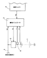
1はバッテリ、2は双方向電流制御装置、3は電池コントローラ、4は車両用ECUである。バッテリ1は双方向電流制御装置2を通じて電源ライン5に接続され、電源ライン5を通じて図示しない車載の各電気負荷や発電機に接続されている。6はバッテリ1の充放電電流を検出する電流センサである。
(overall structure)
1 is a battery, 2 is a bidirectional current control device, 3 is a battery controller, and 4 is a vehicle ECU. The
バッテリ1の電圧V、電流I、並びに、電源ライン5の電圧である電源電圧VLは、マイコン内蔵の電池コントローラ3に入力される。電池コントローラ3は、車両用ECU4から指定される電源電圧VLの目標値(制御電圧とも言う)Vaに基づいて双方向電流制御装置2を通じてバッテリ1の充放電電流を制御して電源電圧VLを制御電圧Vaに収束させる電源電圧安定化制御を行う。下記の説明では、バッテリ1の充放電電流は、双方向電流制御装置2により制御されるため、制御電流Isとも呼称される。
The voltage V and current I of the
(電源電圧安定化制御)
電池コントローラ3が行う電源電圧安定化制御動作を図2を参照して説明する。
(Power supply voltage stabilization control)
The power supply voltage stabilization control operation performed by the
まず、バッテリ1の電圧V、電流I、制御電圧Va、及び、電源ライン5の電圧である電源電圧VLを読み込み(S1000)、あらかじめ記憶するか今回創成したバッテリ1の電圧と電流との間の関係に電源電圧の目標値である制御電圧Vaを代入して、この制御電圧Vaに対応するバッテリ1の電流の目標値である制御電流Isを算出し(S2000)、この制御電流Isを双方向電流制御装置2に送信する(S3000)。双方向電流制御装置2は、たとえば双方向電流制御回路であって、バッテリ1の充放電電流がこの制御電流Isとなるように内蔵スイッチング素子をスイッチング制御する。その後、走行終了かどうかを判定し(S4000)、走行中ならステップS1000にリターンする。なお、電池コントローラ3は、上記した制御電流Isの算出関数をあらかじめ求めるために、定期的に又は所定のバッテリ状態にて実施される割り込みルーチンを有しており、この割り込みルーチンは、入力情報に基づいて演算誤差が小さい制御電流Isの算出関数を選択する処理を行う。したがって、ステップS2000は割り込みルーチンにて演算された制御電流Isの値を読み出す処理となっている。
First, the voltage V, current I, control voltage Va of the
(変形態様)
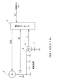
図1に示す車両用電源電圧制御装置の変形態様を図3に示す。この変形態様は、図1において双方向電流制御装置2で行っていたバッテリ1の充放電電流制御を発電機7側にて行うようにすることにより、双方向電流制御装置2を省略したものである。
(Modification)
FIG. 3 shows a modification of the vehicle power supply voltage control apparatus shown in FIG. In this modification, the charging / discharging current control of the
この変形態様の電源電圧安定化制御動作を説明する。まず、バッテリ1の電圧V(=電源電圧VL)、電流I、並びに、発電機7の出力電流(発電電流)IGを読み込み、次にあらかじめ記憶するか今回創成したバッテリ1の電圧と電流との間の関係に電源電圧の目標値である制御電圧Vaを代入してバッテリ1の電流の目標値である制御電流Isを算出し、その後、制御電流Isと発電電流IGとバッテリ1の実測電流Iとから次回に発電機7が出力すべき発電電流IGSを次式から算出する。
IGS=(IGーI)+Is
The power supply voltage stabilization control operation of this modification will be described. First, the voltage V of the battery 1 (= power supply voltage VL), the current I, and the output current (power generation current) IG of the generator 7 are read, and then stored in advance or the voltage and current of the
IGS = (IG-I) + Is
すなわち、(IGーI)は車載の電気負荷の消費電流合計であり、これと今回の制御電流Isの合計に次回の発電電流IGSが一致するように発電機7に発電電流IGSの出力を指令する。発電機7に内蔵されたレギュレータは、指令された発電電流IGSに対応する界磁電流値を演算し、界磁電流値に相当する界磁電流が界磁コイルに通電する。これにより、上記実施例1と同様にバッテリ1の特性を加味した車両用電源電圧制御を実現することができる。
That is, (IG-I) is the total current consumption of the in-vehicle electric load, and the generator 7 is instructed to output the generated current IGS so that the next generated current IGS matches the total current control current Is. To do. The regulator built in the generator 7 calculates a field current value corresponding to the commanded generation current IGS, and a field current corresponding to the field current value is supplied to the field coil. Thereby, the power supply voltage control for vehicles which considered the characteristic of the
(回帰直線を用いた制御電流Is決定方法の説明)
(回帰直線の選択)
ステップS2000で用いる制御電流Isを算出する処理を図4を参照して説明する。
(Description of control current Is determination method using regression line)
(Regression line selection)
Processing for calculating the control current Is used in step S2000 will be described with reference to FIG.
なお、この実施例では、複数の算出関数(制御電流Is算出式)すなわち回帰式により定義される回帰線を用いており、状況に応じてそのうちの好適な一つを選択して制御電流Isの算出を行う。また、新たな算出関数の算出において単に電圧・電流ペアの今回値を追加する以外に過去の算出関数をバッテリ状態に応じて修正することも行う。下記の実施例にて用いる各制御電流Is算出式は、回帰直線も用いたがそれに限定されない。たとえば、多数の電圧・電流ペアがプロットされた二次元平面に所定曲率の回帰曲線を創成し、この回帰曲線に目標電圧を代入して制御電流Isを算出しても良いし、この回帰曲線式上の実測座標点の接線と目標電圧を示す線との交点座標の電流値を制御電流Isとしてもよい。 In this embodiment, a plurality of calculation functions (control current Is calculation formula), that is, regression lines defined by regression formulas are used, and a suitable one of them is selected according to the situation, and the control current Is is selected. Perform the calculation. Further, in addition to simply adding the current value of the voltage / current pair in calculating a new calculation function, the past calculation function is also corrected according to the battery state. Each control current Is calculation formula used in the following examples uses a regression line, but is not limited thereto. For example, a regression curve having a predetermined curvature may be created on a two-dimensional plane on which a large number of voltage / current pairs are plotted, and the control current Is may be calculated by substituting the target voltage into this regression curve. The current value at the intersection coordinate between the tangent line of the upper measured coordinate point and the line indicating the target voltage may be used as the control current Is.
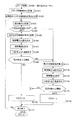
図4おいて、ルーチンはスタータ始動により開始され(S100)、スタータ始動によるバッテリ1の大きな電流変化期間に多数の電圧・電流ペアを計測する(S101)。次に、エンジン始動期間に採取した多数の電圧・電流ペアを用いてバッテリ1の内部抵抗Rを算出して記憶する(S102)。
In FIG. 4, the routine is started by starter start (S100), and a large number of voltage / current pairs are measured during a large current change period of the
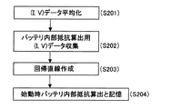
ステップS102の内部抵抗Rの算出処理を図5を参照して更に詳しく説明する。スタータ始動に取得した多数の電圧・電流ペア群を用いて電圧・電流ペアの群を平均化することにより、計測時のノイズ成分を除去する(S201)。次に、安定して計測、取得できること、また始動時の電圧降下を予測する時に推定電圧値と実測電圧値との差が最小になるバッテリ内部抵抗を算出できる電流、電圧範囲となるようにたとえばスタータに最初に流れる突入時の電圧・電流ペアから電圧が下限値となってから回復する時の電圧・電流ペアを選択する(S202)。次に、選択した電圧・電流ペア群から公知の方法で回帰直線(始動時回帰直線)を創成し、その傾きを内部抵抗として算出して記憶する(S204)。 The calculation process of the internal resistance R in step S102 will be described in more detail with reference to FIG. By averaging a group of voltage / current pairs using a number of voltage / current pair groups acquired at starter start, noise components at the time of measurement are removed (S201). Next, the current and voltage range can be calculated so that the battery internal resistance can be calculated so that the difference between the estimated voltage value and the measured voltage value can be minimized when predicting the voltage drop at start-up. A voltage / current pair for recovery after the voltage reaches the lower limit is selected from the voltage / current pair at the time of first flowing into the starter (S202). Next, a regression line (starting regression line) is created from the selected voltage / current pair group by a known method, and the slope is calculated and stored as an internal resistance (S204).
その後、走行開始とともに再び電圧・電流ペアを採取し(S103)、制御電流Is算出方式(内部抵抗利用制御電流算出方式と言う)を選択するためのフラグが0かどうかを調べる(S104)。ここで、フラグの値0は、後述するステップS105〜ステップS107に示す内部抵抗利用制御電流算出方式を制御電流Isの算出に用いるべきことを示し、フラグの値1は、後述するステップS111〜ステップS113に示す回帰線利用制御電流算出方式を制御電流Isの算出に用いるべきことを示す。なお、走行直後は、ルーチン開始直後に行われるリセット初期化ステップによりフラグは0にリセットされる。したがって、走行直後にはステップS105に進む。
Thereafter, the voltage / current pair is collected again at the start of traveling (S103), and it is checked whether or not the flag for selecting the control current Is calculation method (referred to as the internal resistance use control current calculation method) is 0 (S104). Here, the flag value 0 indicates that the internal resistance utilization control current calculation method shown in steps S105 to S107 described later should be used for the calculation of the control current Is, and the
ステップS105では、ステップS103にて走行中に採取した電圧・電流ペアからステップS102と同じように回帰直線(走行時回帰直線)を創成し、この走行時回帰直線の傾斜から走行中の内部抵抗Rを算出して記憶する。なお、走行時のバッテリ1の電圧、電流変化が少なく回帰直線を確度良く創成するのに十分な分散をもつ電圧・電流ペアを採用できなかった場合には、始動時回帰直線を用いてよい。
In step S105, a regression line (running regression line) is created from the voltage / current pair collected during traveling in step S103, as in step S102, and the internal resistance R during traveling is determined from the slope of the traveling regression line. Is calculated and stored. Note that when the voltage / current pair having sufficient dispersion to generate a regression line with high accuracy with little change in the voltage and current of the
次に、車両用ECU4から読み込んだ電源ライン5の電源電圧VLの目標値である制御電圧Vaを読み込み(S106)、読み込んだ制御電圧VaとステップS105で算出した内部抵抗Rとから制御電流Isすなわちバッテリ1の充放電電流の目標値を算出し、この制御電流Isを双方向電流制御装置2に指令してバッテリ1の充放電電流をこの制御電流Isに制御させる(S107)。この制御電流Isの算出はたとえば次式で行われる。Vは直前に採取したバッテリ電圧のデータである。
Is=(VーVa)/R
Next, the control voltage Va which is the target value of the power supply voltage VL of the power supply line 5 read from the vehicle ECU 4 is read (S106), and the control current Is, that is, the control current Is calculated from the read control voltage Va and the internal resistance R calculated in step S105. The target value of the charging / discharging current of the
Is = (V-Va) / R
なお、バッテリ1の充放電電流を制御する双方向電流制御装置2は内部抵抗をもつが、この双方向電流制御装置2の内部抵抗Rは相対的に小さいので無視する。すなわち、双方向電流制御装置2はたとえばスイッチングレギュレータのように所定周期所定デューティにて開閉されるため、閉時すなわち電流通電時におけるオン抵抗損失は小さく無視することができるものとする。
The bidirectional
次に、再び電圧・電流ペアを採取し、採取した電圧Vと制御電圧Vaとの間の電圧誤差αを算出し(S108)、この電圧誤差αが所定閾値以下かどうかを判定する(S109)。電圧誤差αが閾値未満なら今回の制御電流Is算出方式は誤差が小さく今後も採用すべきであると判定してステップS103〜ステップS107に示す走行時回帰直線を用いた制御電流Is算出方式(内部抵抗利用制御電流算出方式と言う)を採用するためのフラグ値として0を選択し(S110)、走行が終了したかどうかを判定し(S117)、終了していればルーチンを終了し、終了していなければステップS103に戻る。次に、ステップS104において、フラグが1であれば、ステップS111〜ステップS113に示す第2の回帰直線利用制御電流算出方式を制御電流Isの算出に用いるべく、ステップS111に進む。 Next, a voltage / current pair is sampled again, a voltage error α between the sampled voltage V and the control voltage Va is calculated (S108), and it is determined whether the voltage error α is equal to or less than a predetermined threshold value (S109). . If the voltage error α is less than the threshold value, it is determined that the current control current Is calculation method is small and should be used in the future, and the control current Is calculation method using the travel regression line shown in steps S103 to S107 (internal) 0 is selected as a flag value for adopting the resistance utilization control current calculation method (S110), and it is determined whether or not the traveling is finished (S11 7 ). If not, the process returns to step S103. Next, if the flag is 1 in step S104, the process proceeds to step S111 in order to use the second regression line utilization control current calculation method shown in steps S111 to S113 for calculation of the control current Is.
ステップS111では、ステップS105で走行時回帰直線創成のために選択した電圧・電流ペア群とは異なる電圧・電流ペア群を、ステップS101及びステップS103で採取した電圧・電流ペア群から選択して第2の回帰直線を創成する。この第2の回帰直線のために選択する電圧・電流ペア群としては、たとえば直前の電圧・電流ペアのグループだけを選択しても良く、あるいはすべての電圧・電流ペアを採用しても良く、更には現在のバッテリ1の運転モードと近似する運転モードで採取した電圧・電流ペア群を採用しても良い。現在のバッテリ1の運転モードと近似する運転モードとしては、充電電流増加状態、充電電流減少状態、放電電流増加状態、放電電流減少状態などで区分し、これらの4つの状態のうち現在の状態と同じ状態に所属する電圧・電流ペア群を採用しても良く、あるいは別に算出した残存容量値が近似する電圧・電流ペア群を採用しても良い。
In step S111, a voltage / current pair group that is different from the voltage / current pair group selected for the generation of the regression line at the time of traveling in step S105 is selected from the voltage / current pair group collected in steps S101 and S103. Create 2 regression lines. As the voltage / current pair group to be selected for the second regression line, for example, only the immediately preceding voltage / current pair group may be selected, or all voltage / current pairs may be adopted. Furthermore, a voltage / current pair group collected in an operation mode approximate to the current operation mode of the
次に、車両用ECU4から読み込んだ電源ライン5の電源電圧VLの目標値である制御電圧Vaを読み込み(S112)、読み込んだ制御電圧Vaを第2の回帰直線に代入して制御電流Isすなわちバッテリ1の充放電電流を算出し、この制御電流Isを双方向電流制御装置2に指令してバッテリ1の充放電電流をこの制御電流Isに制御させる(S113)。
Next, the control voltage Va which is the target value of the power supply voltage VL of the power supply line 5 read from the vehicle ECU 4 is read (S112), and the read control voltage Va is substituted into the second regression line to obtain the control current Is, that is, the battery. 1 is calculated, and the control current Is is commanded to the bidirectional
次に、再び電圧・電流ペアを採取し、採取した電圧Vと制御電圧Vaとの間の電圧誤差αを算出し(S114)、この電圧誤差αが所定閾値以下かどうかを判定し(S115)。電圧誤差αが閾値未満なら今回の制御電流Is算出方式は誤差が小さく今後も採用すべきであると判定してステップS103〜ステップS107に示す制御電流Is算出方式(第2の回帰直線を利用する制御電流Is算出式)を採用するためにフラグ値を1にセットし(S116)、走行が終了したかどうかを判定していればルーチンを終了し、終了していなければステップS103に進む。 Next, a voltage / current pair is sampled again, a voltage error α between the sampled voltage V and the control voltage Va is calculated (S114), and it is determined whether the voltage error α is equal to or less than a predetermined threshold value (S115). . If the voltage error α is less than the threshold value, it is determined that the current control current Is calculation method has a small error and should be used in the future, and the control current Is calculation method shown in steps S103 to S107 (using the second regression line) is used. In order to adopt the control current Is calculation formula), the flag value is set to 1 (S116), and if it is determined whether or not the running is finished, the routine is finished, and if not finished, the process proceeds to step S103.
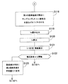
ステップS115において、電圧誤差αが閾値以上なら図6に示すステップS118に進む。 If it is determined in step S115 that the voltage error α is equal to or greater than the threshold value, the process proceeds to step S118 shown in FIG.
(回帰直線の修正)
ステップS118では、ステップS111で算出した第2の回帰直線を、直前の電圧・電流ペアの座標点(Vx、Ix)に平行移動(シフト)して第3の回帰直線(直前シフト回帰直線)とする。次に、制御電圧Vaを読み込み(S119)、この制御電圧Vaを直前シフト回帰直線に代入して制御電流Isを算出する。なお、第2の回帰直線の傾斜角度すなわち内部抵抗をRとすれば、ステップS120での演算は次の式の演算に等しい。
Is=(VxーVa)/R+Ix
(Revision line correction)
In step S118, the second regression line calculated in step S111 is translated (shifted) to the coordinate point (Vx, Ix) of the immediately preceding voltage / current pair to obtain a third regression line (immediately shifted regression line). To do. Next, the control voltage Va is read (S119), and the control current Is is calculated by substituting the control voltage Va into the previous shift regression line. If the inclination angle of the second regression line, that is, the internal resistance is R, the calculation in step S120 is equivalent to the calculation of the following equation.
Is = (Vx-Va) / R + Ix
次に、再び電圧・電流ペアを採取し、採取した電圧Vと制御電圧Vaとの間の電圧誤差αを算出し(S121)、この電圧誤差αが所定閾値以下かどうかを判定し(S122)。電圧誤差αが閾値未満なら今回の制御電流Is算出方式は誤差が小さく今後も採用すべきであると判定してステップS116に進み、電圧誤差αが閾値以上ならステップS123に進む。 Next, a voltage / current pair is sampled again, a voltage error α between the sampled voltage V and the control voltage Va is calculated (S121), and it is determined whether the voltage error α is equal to or less than a predetermined threshold value (S122). . If the voltage error α is less than the threshold value, it is determined that the current control current Is calculation method has a small error and should be used in the future, and the process proceeds to step S116.
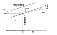
ステップS123では、直前シフト回帰直線の傾斜角度すなわち内部抵抗を電圧誤差αが小さくなる向きに少しの量だけ変更する。この変更を図7に示す説明図を利用して具体的に説明する。 In step S123, the inclination angle of the previous shift regression line, that is, the internal resistance is changed by a small amount so that the voltage error α decreases. This change will be specifically described with reference to an explanatory diagram shown in FIG.
直前の電圧・電流ペアの座標点(Vx、Ix)に平行移動(シフト)して第3の回帰直線(直前シフト回帰直線)とする。図7において、直前シフト回帰直線に制御電圧Vaを代入して得た制御電流Isと、この制御電流Isへバッテリ1の電流を制御した後に得たバッテリ1の実測電圧Vnが目標電圧である制御電圧Vaよりも小さかった場合(図7を参照されたい)には、制御電流Isが増加する向き、すなわち直前シフト回帰直線mの傾斜角度が減少する向きにこの直前シフト回帰直線mの傾斜角度を減少させて新しい回帰直線m+1を創成して記憶する。この新しい回帰直線m+1は次回のステップS111での第2の回帰直線の創成の代わりにステップS112にて利用される。もちろん、バッテリ1の実測電圧Vnが目標電圧である制御電圧Vaよりも大きかった場合には、制御電流Isが減少する向き、すなわち直前シフト回帰直線mの傾斜角度が減少する向きにこの直前シフト回帰直線mの傾斜角度を減少させて新しい回帰直線m+1を創成して記憶する。
A third regression line (immediate shift regression line) is obtained by parallel translation (shift) to the coordinate point (Vx, Ix) of the immediately preceding voltage / current pair. In FIG. 7, the control current Is obtained by substituting the control voltage Va for the previous shift regression line, and the control in which the measured voltage Vn of the
ただし、図6に示す第2の回帰直線の修正は時々停止して、ステップS112にて前回の回帰直線の創成以後に得られた新しい電圧・電流ペアを利用して新規な回帰直線式を時々創成することが好適である。 However, the correction of the second regression line shown in FIG. 6 is sometimes stopped, and a new regression line equation is sometimes created using the new voltage / current pair obtained after the creation of the previous regression line in step S112. It is preferable to create it.
(変形態様)
上記した実施形態では、回帰線として回帰直線を用いたが、非線形な回帰曲線を採用しても良い。この回帰曲線を直前の電圧・電流ペアの座標点にシフトするには二次元平面上にてシフト距離が最小となるように電圧軸及び電流軸にそれぞれ平行に2回平行移動することがこのましい。
(Modification)
In the above-described embodiment, a regression line is used as a regression line, but a nonlinear regression curve may be adopted. In order to shift this regression curve to the coordinate point of the previous voltage / current pair, it is better to translate the voltage curve and current axis twice in parallel so that the shift distance is minimized on the two-dimensional plane. Yes.
(効果)
上記説明したこの実施形態では、走行状況などにより電圧変化が大きい車両用電源系の電源電圧変動を、バッテリの充放電電流をその所定目標値に制御することにより行うため、制御実施によるバッテリの内部状態の変化を加味して電源電圧を調整できるため、制御レスポンスの改善を図ることができる。
(effect)
In this embodiment described above, the power supply voltage fluctuation of the vehicle power supply system, which has a large voltage change depending on the driving situation, is performed by controlling the charge / discharge current of the battery to the predetermined target value. Since the power supply voltage can be adjusted in consideration of the state change, the control response can be improved.
また、上記実施形態では、電圧と電流との間の関係を示す回帰線を直前に採取した電圧・電流ペアの座標点を通るようにシフトするため、演算誤差を低減することができる。 Moreover, in the said embodiment, since the regression line which shows the relationship between a voltage and an electric current is shifted so that it may pass through the coordinate point of the voltage / current pair collected immediately before, a calculation error can be reduced.
また、上記実施形態では、創成した回帰線を用いて得た出力パラメータであるとその実測値との間の演算誤差が大きい場合に、元の回帰線とは異なる電圧・電流ペア群により創成した電圧・電流ペア群を選択して求めた他の回帰線、あるいは元の回帰線とは異なる方法で創成した回帰線を利用して演算を行うため、演算誤差を低減することができる。 In the above embodiment, the output parameter obtained using the created regression line is created with a group of voltage / current pairs different from the original regression line when the calculation error between the measured value and the measured value is large. Since computation is performed using another regression line obtained by selecting a voltage / current pair group or a regression line created by a method different from the original regression line, computation errors can be reduced.
また、上記実施形態によれば、演算誤差が大きい場合に、次回の演算のための回帰線、特にその傾斜角度(内部抵抗)を演算誤差が小さくなるとみなす向きへ修正するので、演算誤差を大幅に低減することができる。 Further, according to the above embodiment, when the calculation error is large, the regression line for the next calculation, in particular, the inclination angle (internal resistance) is corrected to a direction in which the calculation error is considered to be small. Can be reduced.
(実施形態2)
他の実施形態を説明する。この実施形態は、回帰線を決定するに対して、バッテリが放電状態かつ電流増加傾向時の回帰線である放電電流増加時回帰線と、バッテリが放電状態かつ電流減少傾向時の回帰線である放電電流減少時回帰線と、バッテリが充電状態かつ電流増加傾向時の回帰線である充電電流増加時回帰線と、バッテリが充電状態かつ電流減少傾向時の回帰線である充電電流減少時回帰線とを別々に決定しておき、現在のバッテリの状態が上記4つの状態(運転モードと称するものとする)のどれに該当するかを判定し、現在の運転モードと一致する回帰線を用いて電池状態を演算することをその特徴としている。
(Embodiment 2)
Another embodiment will be described. In this embodiment, a regression line is determined, and a regression line when the battery is in a discharged state and a current increasing tendency is a regression line when the battery is in a discharged state and a current is decreasing. The regression line when the discharge current decreases, the regression line when the battery is charged and the current increases, and the regression line when the battery is charged and the current decreases. The regression line when the battery is charged and the current decreases. And determine which of the above four states (referred to as operation mode) corresponds to the current battery state, and use a regression line that matches the current operation mode. It is characterized by calculating the battery state.
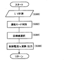
図8に示すフローチャートを参照して更に具体的に説明する。 This will be described more specifically with reference to the flowchart shown in FIG.
まず、電圧・電流ペアを計測し(S300)、この計測した電圧・電流ペアを含む直前の複数の電圧・電流ペアを用いて、現在の電池の運転モードを判別する(S302)。この実施形態では、上記運転モードとして放電電流増加状態、放電電流減少状態、充電電流増加状態、充電電流減少状態の4つの運転モードを設定した。次に、ステップS302で判別した運転モードに一致する回帰線を、予め記憶する4つの回帰線から選択する(S304)。この4つの回帰線は、放電電流増加時回帰線、放電電流減少時回帰線、充電電流増加時回帰線及び充電電流減少時回帰線により構成される。次に、既述の方法で今回計測した電圧・電流ペアが示す座標位置に、今回選択した回帰線をシフトする(S306)。更に具体的に言えば、今回計測した電圧・電流ペアが示す座標位置を通過し、選択した回帰線の傾きをもつ直線を、電圧・電流平面上に引き、この直線上で目標電圧値に該当する座標位置の電流値を制御電流Isとして決定し、出力する。
First, a voltage / current pair is measured (S300), and the current battery operation mode is determined using a plurality of voltage / current pairs immediately before including the measured voltage / current pair (S302). In this embodiment, four operation modes of a discharge current increase state, a discharge current decrease state, a charge current increase state, and a charge current decrease state are set as the operation modes. Next, a regression line that matches the operation mode determined in the step S302, selects four of the regression line for storing in advance (
このようにすれば、用いる回帰線が現在の電池の運転モードと同一の運転モードで作成した回帰線であるため、演算誤差を大幅に減少することができる。 In this way, since the regression line used is a regression line created in the same operation mode as the current battery operation mode, the calculation error can be greatly reduced.
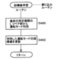
次に、上記4つの回帰線を作成する方法を図9に示すフローチャートを参照して説明する。 Next, a method for creating the four regression lines will be described with reference to the flowchart shown in FIG.
まず、直前の所定期間に採取した複数の電圧・電流ペアから現在の運転モードを判別する(S400)。次に、判別した運転モードに一致する回帰線を、既に記憶する4つの回帰線(放電電流増加時回帰線、放電電流減少時回帰線、充電電流増加時回帰線及び充電電流減少時回帰線)から選択し、この選択した回帰線を更新する(S402)。 First, the current operation mode is determined from a plurality of voltage / current pairs collected during the immediately preceding predetermined period (S400). Next, the four regression lines that have already been stored as the regression line that matches the determined operation mode (return line when discharge current increases, regression line when discharge current decreases, regression line when charge current increases, and regression line when charge current decreases) The selected regression line is updated (S402).
回帰線の更新を放電電流増加時回帰線を例として以下に具体的に説明する。過去に採取された電圧・電流ペアは、上記4つの運転モードにグループ分けされている。直前の所定期間に採取された複数の電圧・電流ペアを、同一運転モード(ここでは放電電流増加状態)の電圧・電流ペアに混ぜて新たにこの運転モード(放電電流増加時)での特性曲線を決定する。なお、今回採取した電圧・電流ペアを混ぜる時に、たとえば最も古い電圧・電流ペアのデータを除外することも可能である。このようにすれば、記憶する回帰線の更新を行うことができる。他の運転モードも同様にして更新することができる。なお、回帰線決定の具体的な算出方式としては、上記の他、直前の回帰線と今回追加する電圧・電流ペアとからより簡単に次の回帰線を決定する算出方式も考えられるが、演算上の問題に過ぎないため説明は省略する。 The update of the regression line will be specifically described below by taking the regression line when the discharge current increases as an example. The voltage / current pairs collected in the past are grouped into the above four operation modes. A characteristic curve in this operation mode (when the discharge current is increased) is newly created by mixing multiple voltage / current pairs collected during the previous specified period with the voltage / current pair in the same operation mode (in this case, the discharge current is increased). To decide. When mixing the voltage / current pairs collected this time, for example, the data of the oldest voltage / current pair can be excluded. In this way, the regression line to be stored can be updated. Other operation modes can be updated in the same manner. As a specific calculation method for determining the regression line, in addition to the above, there is a calculation method for determining the next regression line more easily from the previous regression line and the voltage / current pair added this time. Since it is only the above problem, description is abbreviate | omitted.
1 バッテリ
2 双方向電流制御装置
3 電池コントローラ
5 電源ライン
7 発電機
DESCRIPTION OF
Claims (1)
前記バッテリから検出した複数の電圧・電流ペアに基づいて前記バッテリの電圧と電流との間の回帰線を所定タイミングごとに更新し、
前記目標電圧と前記回帰線とから前記バッテリの電流である制御電流の値を算出し、
前記バッテリの電流を前記制御電流の値に調整することにより、前記バッテリに接続された回路系に印加する電源電圧を所定の目標レベルに収束させることを特徴とする車両用電源電圧制御方法。 In a vehicle power supply voltage control method for controlling a power supply voltage, which is a voltage of a power supply line of a vehicle to which a battery, power generation means, and an electrical load are connected, to a predetermined target voltage,
Updating the regression line between the battery voltage and current based on a plurality of voltage / current pairs detected from the battery at predetermined timings,
From the target voltage and the regression line to calculate the value of the control current that is the current of the battery,
A power supply voltage control method for vehicles, wherein the power supply voltage applied to the circuit system connected to the battery is converged to a predetermined target level by adjusting the current of the battery to the value of the control current .
Priority Applications (5)
| Application Number | Priority Date | Filing Date | Title |
|---|---|---|---|
| JP2006022303A JP4786355B2 (en) | 2006-01-31 | 2006-01-31 | Power supply voltage control method for vehicles |
| DE102007004368.8A DE102007004368B4 (en) | 2006-01-31 | 2007-01-29 | Method and device for controlling the supply voltage of a vehicle |
| KR1020070009585A KR100869584B1 (en) | 2006-01-31 | 2007-01-30 | Method and apparatus for calculating battery state and apparatus for controlling power voltage in vehicle |
| FR0700640A FR2896926A1 (en) | 2006-01-31 | 2007-01-30 | BATTERY CONDITION CALCULATION METHOD AND DEVICE AND POWER SUPPLY VOLTAGE CONTROL DEVICE IN VEHICLE |
| US11/700,183 US7777446B2 (en) | 2006-01-31 | 2007-01-31 | Method and apparatus for calculating battery state and apparatus for controlling power voltage in vehicle |
Applications Claiming Priority (1)
| Application Number | Priority Date | Filing Date | Title |
|---|---|---|---|
| JP2006022303A JP4786355B2 (en) | 2006-01-31 | 2006-01-31 | Power supply voltage control method for vehicles |
Related Child Applications (1)
| Application Number | Title | Priority Date | Filing Date |
|---|---|---|---|
| JP2011107094A Division JP5191014B2 (en) | 2011-05-12 | 2011-05-12 | Battery state quantity calculation method |
Publications (2)
| Publication Number | Publication Date |
|---|---|
| JP2007203788A JP2007203788A (en) | 2007-08-16 |
| JP4786355B2 true JP4786355B2 (en) | 2011-10-05 |
Family
ID=38266145
Family Applications (1)
| Application Number | Title | Priority Date | Filing Date |
|---|---|---|---|
| JP2006022303A Expired - Fee Related JP4786355B2 (en) | 2006-01-31 | 2006-01-31 | Power supply voltage control method for vehicles |
Country Status (5)
| Country | Link |
|---|---|
| US (1) | US7777446B2 (en) |
| JP (1) | JP4786355B2 (en) |
| KR (1) | KR100869584B1 (en) |
| DE (1) | DE102007004368B4 (en) |
| FR (1) | FR2896926A1 (en) |
Cited By (2)
| Publication number | Priority date | Publication date | Assignee | Title |
|---|---|---|---|---|
| CN107171418A (en) * | 2017-07-26 | 2017-09-15 | 深圳天珑无线科技有限公司 | Data processing method, device and non-transitory computer-readable medium |
| CN109066857A (en) * | 2018-08-15 | 2018-12-21 | 深圳市烽焌信息科技有限公司 | The method and charging robot charge to patrol robot |
Families Citing this family (22)
| Publication number | Priority date | Publication date | Assignee | Title |
|---|---|---|---|---|
| JP4786355B2 (en) * | 2006-01-31 | 2011-10-05 | 株式会社日本自動車部品総合研究所 | Power supply voltage control method for vehicles |
| JP4341652B2 (en) * | 2006-09-04 | 2009-10-07 | トヨタ自動車株式会社 | Power storage control device and power storage control method |
| TWI413270B (en) * | 2008-03-12 | 2013-10-21 | Ind Tech Res Inst | Method for forming optimal characteristic curves of solar cell and system thereof |
| JP4499810B2 (en) * | 2008-05-28 | 2010-07-07 | 株式会社日本自動車部品総合研究所 | In-vehicle battery state estimation device |
| US8111037B2 (en) * | 2008-06-27 | 2012-02-07 | GM Global Technology Operations LLC | Method for battery state-of-health monitoring using battery voltage during vehicle starting |
| DE102008041546A1 (en) * | 2008-08-26 | 2010-03-04 | Robert Bosch Gmbh | Method for calculating the state of charge of a battery |
| JP5347583B2 (en) * | 2009-03-09 | 2013-11-20 | トヨタ自動車株式会社 | Battery system, vehicle and battery-equipped equipment |
| US8552693B2 (en) * | 2009-07-17 | 2013-10-08 | Tesla Motors, Inc. | Low temperature charging of Li-ion cells |
| DE102010006965A1 (en) | 2010-02-05 | 2011-08-11 | Continental Automotive GmbH, 30165 | Apparatus and method for determining a range of a battery characteristic |
| JP5719236B2 (en) * | 2011-05-31 | 2015-05-13 | プライムアースEvエナジー株式会社 | Secondary battery control device |
| JP2013221790A (en) * | 2012-04-13 | 2013-10-28 | Toyota Industries Corp | Battery internal state estimating device mounted on vehicle |
| JP5888315B2 (en) * | 2013-12-18 | 2016-03-22 | トヨタ自動車株式会社 | Power storage system |
| DE102014205495A1 (en) * | 2014-03-25 | 2015-10-01 | Robert Bosch Gmbh | Electronic battery sensor and method for determining an internal resistance of a battery |
| JP6549876B2 (en) * | 2015-03-31 | 2019-07-24 | 株式会社Subaru | Power supply for vehicles |
| JP6456809B2 (en) * | 2015-11-30 | 2019-01-23 | 株式会社Subaru | Vehicle power supply |
| KR20170114579A (en) * | 2016-04-05 | 2017-10-16 | 주식회사 만도 | Voltage control method and system thereof |
| US11811248B2 (en) | 2016-07-21 | 2023-11-07 | C.E. Niehoff & Co. | Vehicle generator using battery charging profiles |
| CN107803350B (en) * | 2017-10-31 | 2018-10-02 | 深圳市恒翼能科技有限公司 | A kind of method of lithium battery automatic sorting, storage medium and battery sorting device |
| US11131713B2 (en) * | 2018-02-21 | 2021-09-28 | Nec Corporation | Deep learning approach for battery aging model |
| US10770914B2 (en) | 2018-11-05 | 2020-09-08 | C.E. Niehoff & Co. | Dual control loop for charging of batteries |
| CN111129623B (en) * | 2019-12-31 | 2021-08-17 | 东风小康汽车有限公司重庆分公司 | A kind of vehicle battery charging protection method and system |
| DE102020007411B4 (en) | 2020-12-04 | 2022-10-06 | Mercedes-Benz Group AG | Method for determining a current resistance value of a battery cell in a motor vehicle, and evaluation device |
Family Cites Families (20)
| Publication number | Priority date | Publication date | Assignee | Title |
|---|---|---|---|---|
| JP3084789B2 (en) | 1990-10-12 | 2000-09-04 | 株式会社デンソー | Vehicle charge control device |
| US5280231A (en) * | 1990-07-02 | 1994-01-18 | Nippondenso Co., Ltd. | Battery condition detecting apparatus and charge control apparatus for automobile |
| JP3136926B2 (en) * | 1994-11-08 | 2001-02-19 | 松下電器産業株式会社 | Storage battery status management system |
| JP3540437B2 (en) * | 1995-06-05 | 2004-07-07 | 本田技研工業株式会社 | Battery status determination device |
| JP3387287B2 (en) * | 1995-09-19 | 2003-03-17 | 日産自動車株式会社 | Regenerative charging control device |
| JP3520886B2 (en) | 1996-03-08 | 2004-04-19 | サンケン電気株式会社 | Rechargeable battery status determination method |
| KR100247115B1 (en) * | 1996-09-11 | 2000-03-15 | 정병천 | Automotive Battery Discharge Prevention Device |
| JPH1138105A (en) | 1997-07-15 | 1999-02-12 | Toyota Autom Loom Works Ltd | Method for calculating residual capacity of battery and method for outputting alarm to insufficient residual capacity |
| JP3395694B2 (en) * | 1999-03-09 | 2003-04-14 | 日産自動車株式会社 | Calculation method for battery capacity deterioration of secondary battery |
| JP2001069680A (en) * | 1999-08-24 | 2001-03-16 | Auto Network Gijutsu Kenkyusho:Kk | Vehicle power supply |
| JP4491917B2 (en) * | 2000-06-02 | 2010-06-30 | ソニー株式会社 | Battery pack |
| US6268712B1 (en) * | 2000-09-26 | 2001-07-31 | Vb Autobatterie Gmbh | Method for determining the starting ability of a starter battery in a motor vehicle |
| JP3711881B2 (en) | 2001-03-12 | 2005-11-02 | 日産自動車株式会社 | Charge / discharge control device |
| DE10125819B4 (en) * | 2001-05-26 | 2013-06-06 | Burani Consulting Limited Liability Company | Method and device for determining the startability of a vehicle |
| JP3671901B2 (en) * | 2001-11-21 | 2005-07-13 | 日産自動車株式会社 | Capacity display device and capacity display method |
| JP4038788B2 (en) | 2002-02-22 | 2008-01-30 | アクソンデータマシン株式会社 | Battery remaining capacity determination method and apparatus |
| US6850038B2 (en) * | 2002-05-14 | 2005-02-01 | Yazaki Corporation | Method of estimating state of charge and open circuit voltage of battery, and method and device for computing degradation degree of battery |
| JP2004031014A (en) | 2002-06-24 | 2004-01-29 | Nissan Motor Co Ltd | Method and apparatus for calculating maximum charge / discharge power of battery pack including parallel connected batteries |
| JP2005206085A (en) * | 2004-01-23 | 2005-08-04 | Sumitomo Electric Ind Ltd | Power distribution system, power distributor, and brake device |
| JP4786355B2 (en) * | 2006-01-31 | 2011-10-05 | 株式会社日本自動車部品総合研究所 | Power supply voltage control method for vehicles |
-
2006
- 2006-01-31 JP JP2006022303A patent/JP4786355B2/en not_active Expired - Fee Related
-
2007
- 2007-01-29 DE DE102007004368.8A patent/DE102007004368B4/en not_active Expired - Fee Related
- 2007-01-30 KR KR1020070009585A patent/KR100869584B1/en not_active Expired - Fee Related
- 2007-01-30 FR FR0700640A patent/FR2896926A1/en not_active Withdrawn
- 2007-01-31 US US11/700,183 patent/US7777446B2/en not_active Expired - Fee Related
Cited By (2)
| Publication number | Priority date | Publication date | Assignee | Title |
|---|---|---|---|---|
| CN107171418A (en) * | 2017-07-26 | 2017-09-15 | 深圳天珑无线科技有限公司 | Data processing method, device and non-transitory computer-readable medium |
| CN109066857A (en) * | 2018-08-15 | 2018-12-21 | 深圳市烽焌信息科技有限公司 | The method and charging robot charge to patrol robot |
Also Published As
| Publication number | Publication date |
|---|---|
| KR20070079029A (en) | 2007-08-03 |
| DE102007004368B4 (en) | 2019-12-05 |
| DE102007004368A1 (en) | 2007-08-16 |
| KR100869584B1 (en) | 2008-11-21 |
| US20070182385A1 (en) | 2007-08-09 |
| FR2896926A1 (en) | 2007-08-03 |
| US7777446B2 (en) | 2010-08-17 |
| JP2007203788A (en) | 2007-08-16 |
Similar Documents
| Publication | Publication Date | Title |
|---|---|---|
| JP4786355B2 (en) | Power supply voltage control method for vehicles | |
| JP6029751B2 (en) | Storage battery state detection device and storage battery state detection method | |
| CN110549900B (en) | Parameter update method and device for electric vehicle and power battery after standing still | |
| CN107181312B (en) | Vehicle power system | |
| CN111864282B (en) | Remaining power correction method, power automobile and readable storage medium | |
| US20120215517A1 (en) | Method for Determining and/or Predicting the Maximum Power Capacity of a Battery | |
| JP2008189090A (en) | Vehicle control device | |
| JP6100595B2 (en) | Crude range calculation device | |
| KR101887770B1 (en) | Method and system for limiting output power of fuelcell | |
| JP4630113B2 (en) | Secondary battery deterioration state determination method and secondary battery deterioration state determination device | |
| CN115959012B (en) | Start-stop control method and device for fuel cell engine, vehicle and storage medium | |
| JP2010024906A (en) | Automatic stop/start device for internal combustion engine | |
| CN102540085B (en) | The optimization method of electric component parameter and system in energy-storage system model | |
| JP2019030189A (en) | Power system | |
| JP5191014B2 (en) | Battery state quantity calculation method | |
| JP4407826B2 (en) | Power generation control device for internal combustion engine | |
| JP5562195B2 (en) | Charge control device | |
| US11137451B2 (en) | Battery resistance measuring device | |
| US20230411708A1 (en) | Battery device | |
| KR20210038127A (en) | Method of Predicting SOC Control Based On Variable Time and Vehicle Thereof | |
| JP2017146194A (en) | Secondary battery diagnosis device | |
| JP2007057422A (en) | Current sensor error correction device | |
| JP7363448B2 (en) | electronic equipment | |
| JP7334769B2 (en) | AUTOMATIC DRIVING CONTROL DEVICE, VEHICLE, AND AUTOMATIC DRIVING CONTROL METHOD | |
| JP4492802B2 (en) | Air-fuel ratio control device |
Legal Events
| Date | Code | Title | Description |
|---|---|---|---|
| A621 | Written request for application examination |
Free format text: JAPANESE INTERMEDIATE CODE: A621 Effective date: 20080516 |
|
| A977 | Report on retrieval |
Free format text: JAPANESE INTERMEDIATE CODE: A971007 Effective date: 20110303 |
|
| A131 | Notification of reasons for refusal |
Free format text: JAPANESE INTERMEDIATE CODE: A131 Effective date: 20110315 |
|
| A521 | Request for written amendment filed |
Free format text: JAPANESE INTERMEDIATE CODE: A523 Effective date: 20110512 |
|
| TRDD | Decision of grant or rejection written | ||
| A01 | Written decision to grant a patent or to grant a registration (utility model) |
Free format text: JAPANESE INTERMEDIATE CODE: A01 Effective date: 20110712 |
|
| A01 | Written decision to grant a patent or to grant a registration (utility model) |
Free format text: JAPANESE INTERMEDIATE CODE: A01 |
|
| A61 | First payment of annual fees (during grant procedure) |
Free format text: JAPANESE INTERMEDIATE CODE: A61 Effective date: 20110713 |
|
| R150 | Certificate of patent or registration of utility model |
Ref document number: 4786355 Country of ref document: JP Free format text: JAPANESE INTERMEDIATE CODE: R150 Free format text: JAPANESE INTERMEDIATE CODE: R150 |
|
| FPAY | Renewal fee payment (event date is renewal date of database) |
Free format text: PAYMENT UNTIL: 20140722 Year of fee payment: 3 |
|
| R250 | Receipt of annual fees |
Free format text: JAPANESE INTERMEDIATE CODE: R250 |
|
| R250 | Receipt of annual fees |
Free format text: JAPANESE INTERMEDIATE CODE: R250 |
|
| R250 | Receipt of annual fees |
Free format text: JAPANESE INTERMEDIATE CODE: R250 |
|
| R250 | Receipt of annual fees |
Free format text: JAPANESE INTERMEDIATE CODE: R250 |
|
| R250 | Receipt of annual fees |
Free format text: JAPANESE INTERMEDIATE CODE: R250 |
|
| R250 | Receipt of annual fees |
Free format text: JAPANESE INTERMEDIATE CODE: R250 |
|
| R250 | Receipt of annual fees |
Free format text: JAPANESE INTERMEDIATE CODE: R250 |
|
| R250 | Receipt of annual fees |
Free format text: JAPANESE INTERMEDIATE CODE: R250 |
|
| R250 | Receipt of annual fees |
Free format text: JAPANESE INTERMEDIATE CODE: R250 |
|
| LAPS | Cancellation because of no payment of annual fees |