JP4783533B2 - FAIMS apparatus and method using carrier gas of mixed composition - Google Patents
FAIMS apparatus and method using carrier gas of mixed composition Download PDFInfo
- Publication number
- JP4783533B2 JP4783533B2 JP2001567612A JP2001567612A JP4783533B2 JP 4783533 B2 JP4783533 B2 JP 4783533B2 JP 2001567612 A JP2001567612 A JP 2001567612A JP 2001567612 A JP2001567612 A JP 2001567612A JP 4783533 B2 JP4783533 B2 JP 4783533B2
- Authority
- JP
- Japan
- Prior art keywords
- gas
- ions
- electric field
- ion
- analysis region
- Prior art date
- Legal status (The legal status is an assumption and is not a legal conclusion. Google has not performed a legal analysis and makes no representation as to the accuracy of the status listed.)
- Expired - Fee Related
Links
Images


Classifications
-
- H—ELECTRICITY
- H01—ELECTRIC ELEMENTS
- H01J—ELECTRIC DISCHARGE TUBES OR DISCHARGE LAMPS
- H01J49/00—Particle spectrometers or separator tubes
- H01J49/004—Combinations of spectrometers, tandem spectrometers, e.g. MS/MS, MSn
-
- G—PHYSICS
- G01—MEASURING; TESTING
- G01N—INVESTIGATING OR ANALYSING MATERIALS BY DETERMINING THEIR CHEMICAL OR PHYSICAL PROPERTIES
- G01N27/00—Investigating or analysing materials by the use of electric, electrochemical, or magnetic means
- G01N27/62—Investigating or analysing materials by the use of electric, electrochemical, or magnetic means by investigating the ionisation of gases, e.g. aerosols; by investigating electric discharges, e.g. emission of cathode
- G01N27/622—Ion mobility spectrometry
- G01N27/624—Differential mobility spectrometry [DMS]; Field asymmetric-waveform ion mobility spectrometry [FAIMS]
Abstract
Description
【0001】
(技術分野)
本発明は、イオン分離装置および方法に関し、詳細には、本発明は、高電場非対称波形イオン移動度解析法(以下、「FAIMS」という)のイオン集束原理に基づくイオン分離装置および方法に関する。
【0002】
(背景技術)
運搬可能な場の適用法のための小型化に伴う高い感度および敏感さが、イオン移動度解析法(以下、「IMS」という。)を、多数の化合物、麻酔剤、爆薬、化学兵器薬剤の発見のための重要な技術たらしめることに役立っている。この点は例えば、G.Eiceman およびZ.Karpasによる、「イオン移動度解析法」(CRC、 Boca Raton, 1994)という題名の本に記載されている。IMSでは、気相イオン移動度は、一定電場をもったドリフト管を用いて決定される。イオンは、ドリフト管内にゲート制御され、それらの移動速度の差異に依存して実質上分離される。イオン移動速度は低電場強度では、電場の強度に比例する。例えば、200V/cmでは、実験から決定された移動度Kは、印加された電場に独立である。加えて、IMSでは、イオンは十分に高い圧力の浴用気体を通して移動し、時間的空間的に一定の電場の力によってイオンは高速に一定速度に到達する。この点は、大部分が質量分析法に関係する技術とは明瞭に異なる。これらの技術では一定電場の影響下であれば、イオンが加速し続ける程度に、気体の圧力は十分に低いものである。
【0003】
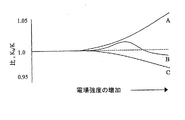
E.A.Mason およびE.W.McDaniel は、「気体中のイオンの輸送性」という題名の本(Wiley, ニューヨーク、1988)で、高い電場の強度、例えば、約5,000V/cmより強い場では、イオン移動速度は、及ぼされた場に直接的にはもはや比例せず、Kは印加された電場に依存するようになる。高電場強度では、Kは、非定数高電場移動度項Khで表されるのが適当である。印加された電場へのKhの依存性は高電場非対称波形イオン移動度解析法(FAIMS)の開発の基礎であり、この語句は発明者によって明細書中で用いられており、横方向電場補償イオン移動度解析法または場イオン解析法とも呼ばれている。イオンは、FAIMSで、高電場強度でのイオンの移動度における差異に基づいて分離され、その移動度Khは、低電場強度でのイオン移動度Kと関連している。言い換えれば、イオンは、印加された電場の関数として、Khの複雑な依存的振る舞いのために分離される。測定するのはイオン移動度における変化であって、イオン移動度の絶対値ではないという点で、FAIMSは大気圧気体相の研究に新しい道具を提供する。
【0004】
平面電極を用いるFAIMSの操作の原理は、I.A.Buryakove, E.V.Krylov, E.G.NararovおよびU.KH.Rasulevによる、質量分析法およびイオン過程の国際ジャーナル(International Journal of Mass Spectrometry and Ion Processes)、第28巻(1993)、143頁〜148頁の論文で、発表された。電場の下で与えられたイオンの移動度は、Kh=K(1+F(E))によって表される。ここで、Khは高電場強度でのイオン移動度、Kは低電場強度でのイオン移動度の係数であり、F(E)はイオン移動度の電場への関数的な依存性を表している。イオンは、印加された電場の強度の関数としてイオン移動度における変化に基づいて、3つの広いカテゴリーの1つに分類されている。タイプAのイオンの移動度は、電場強度とともに増加し、タイプCのイオンの移動度は減少し、タイプBのイオンの移動度は、さらに高電場強度で減少する前に最初に増加する。FAIMSでのイオンの分離は、高電場強度での移動度の変化に基礎を置いている。イオン、例えば、タイプAのイオンが、FAIMS装置の2つの離間した平行な金属板電極間の気体流によって運ばれる場合を考える。その金属板の間の空間は、イオンの分離が行われる解析領域を表す。前記金属板間のイオンの正味の動作は、気体の流れによる水平のx軸成分と平行金属板電極間の電場による横のy軸成分の和である。「正味の動作」という語句は、たとえ並進運動がその上に重畳されたより速い振動をもつ場合でさえ、イオン、例えば、上記タイプAイオンが経験する全並進運動を表す。しばしば、第1の金属板は、第2の金属板がその上に印加された非対称波形、V(t)をもつのに対して、基底状態のポテンシャルが維持されている。非対称波形V(t)は、高圧成分V1が時間t2の短時間続いた後、反対極の低圧成分V2が時間t1より長い時間続くパターンの繰り返しからなっている。その波形は、波形の完全な一周期間に金属板に印加される積分された電圧時間積およびそのような電場―時間積が0である。例えば、V1 t2+V2t1=0に対して例えば、10μsの間2,000Vで、次に20μsの間-1,000Vである。短期間の方の最高電圧、すなわち、波形の高電圧部分は、「分散電圧」またはこの開示ではDVと呼んでいる。
【0005】
波形の高電圧部分の間、電場はイオンをV1=KhEhigh の横方向のy軸速度成分で移動させる。ここで、Ehighは印加された電場であり、Khは周囲の電場、圧力および温度条件の下での高電場イオン移動度である。移動した距離はD1=V1t2=KhEhight2であり、t2は、印加された高電圧の時間周期である。反対の極性をもつ低電圧部分の前記非対称波形の長時間期間の間に、イオンのy軸の速度成分は、V2=KElow、であり、Kは周囲の圧力および温度の条件の下での低圧イオン移動度である。移動した距離は、d2= V2t1= KElowt1である。非対称波形は、(V1t2)+(V2t1)=0と保証しているので、電場‐時間積Ehight2およびElowt1は、大きさが等しい。このようにして、KhおよびKが同一である場合には、d1とd2は等しく、負の波形の周期の間にイオンはy軸に沿って元の位置に戻る。このことは、もし波形の両方の部分が低電圧である場合に予想される。もし、Ehighで、移動度がKh>Kである場合には、イオンは、y軸に関して元の位置からの正味の変移を経験する。例えば、タイプAの正のイオンが、波形の正の位置の間により遠く、例えば、d1>d2に移動し、タイプAのイオンは、第2の金属板から移動する。同様にして、タイプCの正のイオンは第2の金属板に向かって移動する。
【0006】
もし、タイプAの正のイオンが第2の金属板から移動するのなら、一定の負のDC電圧が、この横移動を逆転し、または「補償する」ために第2の金属板に印加される。このDC電圧は、「補償電圧」またはこの発表では、CVと呼ばれ、イオンが、第2または第1の金属板のどちらかへの移動を防止する。もし、2つの化合物から導かれたイオンが、印加された高強度電場に対して異なるように応答するならば、Kに対するKhの比は、各化合物に対して異なる。このようにして、イオンの種々の種類を含有する混合物が、FAIMSによって分析されるならば、イオンの唯一の種類がCVとDVの与えられた組合せに対して選択的に送られる。イオンの残りの種類、例えば、FAIMSを通じて選択的に送られたもの以外のイオンは、FAIMSの平行な金属板電極の一方に向けて移動し、中性化される。もちろん、イオンの残りの種類がFAIMSの電極に向かって移動する速度は、CVおよびDVの一般的な条件の下での選択的に送られたイオンの速度とは異なる高電場移動性の程度に依存する。
【0007】
前述したようなFAIMS原理に応じて機能する道具は、イオンフィルターであって、Kに対するKhの適当な比を持ったイオンのみの選択的な移送が可能である。FAIMSを用いる1のタイプの実験において、印加されたCVが時間によって走査され、例えば、CVはゆっくりと斜面が付けられまたは希望により、CVはある電圧値から次の電圧値に変化され、移送されたイオンの強度結果が測定される。このようにして、CVの関数として全イオン流を示すCVスペクトルが得られる。CVスペクトルに表れた極値の同一性は、1種類のイオンの移送についてのCVに基づいてのみ明確に確定されるものとは異なるということが、電子測定検出機を使用した初期のFAIMS装置の重大な限界である。この限界は、電場強度におけるKhの予測不能な化合物−特性依存性が原因である。言い換えれば、CVスペクトルでの極値は、誤って簡単に1化合物へ割り当てられる。なぜならば、例えば、イオンの構造から、どこにそのイオンがCVスペクトルに現れるべきかということを前もって予測しまたは評価する方法がないからである。言い換えれば、正しくCVスペクトルにおける極値を割り当てる見込みを改良するためには、追加の情報が必要である。例えば、選択的に移送されたイオンのそれに続く質量分析的解析は、CVスペクトルの極値の指定の正確さを非常に高める。
【0008】
1995年5月30日に発行された米国特許第5,420,424において、B.L.CarnahanおよびA.S.Tarassoveは、改良されたFAIMS電極配置構造を開示し、該配置構造中においてイオンの分離に用いる平坦な金属板が、同心の円柱で置き換えられており、その配置構造の内容をここに引用する。同心の円柱の設計は、いくつかの利点があり、その利点には、平坦な金属板の配置構造と比較してより高い感度が含まれる。これは、R.W.Purves, R.Gueveremont, S.Day, C.W.Pipich およびM.S.Maryjaszczykによって、科学的装置のレヴュー(Reviews of Scientific Instruments)、第69巻(1998)第4094〜第4105頁、に発表された論文で議論されている。円柱状のFAIMSの高い感度は、同心の円柱状電極間の解析領域で発生する2次元の大気圧のイオン焦点効果に基づく。電圧が円柱に印加されていない場合には、イオンの半径方向分布はFAIMS解析機を横切って略均一である。しかしながら、DVおよびCVの印加の間には、半径方向のイオンの分布は、FAIMSの解析領域の環状空間を通じて均一ではない。好都合なことには、目的イオンに対する適当なDVおよびCVの印加によって、これらのイオンは電極間の帯域に集束するようになり、イオンの損失率を、FAIMS電極との衝突の結果として、減少させることができる。目的イオンのFAIMSの解析領域を通る移送の効率は、この2次元の焦点効果の結果として増進される。
【0009】
非対称波形の使用によるイオンの集束化についてこれまで議論してきた。完全を期するために、円柱状配置構造のFAIMSの解析領域内に集束していないイオンの振る舞いを簡単にここで記述する。以前議論したように、高電場イオン移動性を有するイオンであって、DVとCVの与えられた組および配置構造条件の下で集束するために適当ではないものはFAIMS装置の1または他の壁部に向かって移動するだろう。これらのイオンが壁部に向かって移動する速度は、前述した条件の下で選択的に移送されたイオンの速度と異なるKh/Kの程度に依存する。極端な場合では、完全に都合の悪い性質を持つイオン、例えば、タイプAのイオンは、タイプCのイオンに比較して、FAIMS装置の壁で非常に早く消失する。
【0010】
FAIMS装置でのイオンの消失は、もう1つの方法で考察されるべきである。例えば、与えられた配置構造で、2,500ボルトのDVおよび-11ボルトのCVでもしタイプAのイオンが集束すると、もし、例えば-2,500ボルトのDVおよび+11ボルトのCVのようにDVとCVの極性が反転すると、イオンはまた集束すると予想するのが合理的なように見えるだろう。しかしながら、これは観測されず、事実このような態様での極性の反転は、FAIMSのイオン集束動作の鏡像効果を生み出す。このような極性反転の結果は、イオンは集束されず、むしろ装置から非常に速く除去される。集束谷の鏡像は、山状のポテンシャル表面である。イオンは、集束ポテンシャル谷(2または3次元)の中央にすべるように進む。しかし、山状の表面の頂点から滑り去り、電極の壁部を打つ。これが1および2と呼ばれる独立モードの、円柱状のFAIMSにおける存在の理由である。このようなFAIMS装置は4つの可能なモードP1、P2、N1およびN2のうちの1つで操作される。「P」および「N」は、イオンの極性、正(P)および負(N)を記述する。DVが非対称波形の高電圧部分の電圧の極値を表すとすると、正のDVを持つ波形はタイプP1およびN2のスペクトルを生じ、反転した負の極性を持つDVの波形はP2およびN1を生ずる。ここまでの議論は、正のイオンを考慮したが、しかし、一般に、同一の原理が負のイオンにも等しく適用される。
【0011】
円柱状FAIMSの設計に対する更なる改良が、内部の電極の曲面を持つ端部を設けることによって実現されている。曲面を持つ端部は内部の電極の円柱形状と連続し、FAIMS解析領域のイオン吐出口と同軸に配列されている。非対称波形の内部電極への印加は上述した通常のイオン集束動作に帰着するが、内部電極の一般的に球状の端部の周りに延長する点が異なる。これは選択的に移送されたイオンは内部電極の端部の周囲にある領域から逃れることができないことを意味している。これは、もし内部電極に印加された電圧が、2次元の集束に関連して上記議論中で記述したようにCVとDVとの適当な組合せである場合にのみ生ずる。もしCVおよびDVが、FAIMSの解析領域でのイオンの集束に適当であって、外部の電極の内面の物理的配置が、このバランスを乱さないならば、イオンは端部の近傍にある3次元領域空間内に集束するだろう。いくつかの反力が内部電極の端部近傍にあるこの領域にあるイオンに作用する。キャリヤガスの流れによる力はイオン吐出口に向かって移動するイオン雲に影響を与える傾向にある。都合の良いことには、このことは、捕獲されたイオンが逆方向、すなわち、イオン化源への戻り方向、に移動することを防止する。加えて、印加された電場の集束動作により、内部電極にあまりに接近するイオンは内部電極から離れるように押し戻され、外部電極近くのイオンは内部電極の方に戻る。イオンに作用する全力が釣り合うと、流れる気体の力により、またはFAIMSの電場の集束効果により、イオンはあらゆる方向で効率的に捕獲される。これは、R.Guvremont およびR.GueveremontおよびR.Purvesの名義の係属中のPCT出願に開示されているように、3次元大気圧イオン捕獲の例であり、その内容をここに引用する。
【0012】
イオン集束およびイオン捕獲は空間的に一定以外の、通常、電極が曲がっていて、および/または相互に平行でないFAIMSの幾何学的配置で生じる。例えば、空間的に一定でない電場は、円柱またはその一部、球状の電極またはその一部、円錐状の電極またはその一部を使用することで生じる。随意に、これらの電極の形状の種々の組合せが使用される。
【0013】
上で議論したように、円柱状のFAIMS技術の1つの従来の限界は、CVスペクトルで現れる極値は、高電場強度でのKhにおける予想できない変化に起因してあいまいに確認される。こうして、FAIMS概念に基礎を置いた装置の能力を広げる1つの方法は、FAIMS装置からイオンを、対電荷質量(m/z)解析のための質量分析計に導入するように、CVスペクトルの組立てをより正確に決定する方法を提供することである。好都合なことには、円柱状のFAIMS装置のイオン集束性はイオンをFAIMSの解析領域から外部のサンプル穴、例えば質量分析計の引入口に移送するための効率を増大するように作動する。イオンを質量分析計の引入口に移送するための改良された効率は、ほぼ捕獲条件で操作されたFAIMSの3次元捕獲バージョンを使用することによって随意に極大化される。ほぼ捕獲条件下では、内部電極の球状端近傍の空間の3次元領域に集まったイオンは、イオン吐出口の穴に向かう流れによって引き寄せられ、この領域から洩れ出る。この領域から洩れ出るイオンは、狭い、略平行化した光線のように洩れ出て、イオン吐出口を通り質量分析計の真空システムに導く小さな穴へ進む気体流により引き寄せられる。
【0014】
加えて、FAIMS装置の分解能は、電場強度の関数と同様の移動性を持つイオンが予め定めた操作条件の組の下で分離される程度を表す表現で定義される。こうして、高分解能FAIMS装置は選択的に、同様の移動性をもつ種々のイオン種類の相対的に小さな領域を移送するのに対し、低分解能FAIMS装置は同様の移動性をもつ種々のイオン種類の比較的大きな領域を移送する。円柱状配置構造のFAIMSにおけるFAIMSの分解能は平行金属板配置構造のFAIMSにおける分解能よりも劣っている。これは、円柱状配置構造のFAIMSはイオンを集束化する能力を持っているからである。この集束動作は、広い移動性の範囲にあるイオンが同時に円柱状配置構造のFAIMSの解析領域に集束することを意味する。狭い電極を持った円柱状配置構造のFAIMSは最強の集束動作をもつが、イオンの分離に対する最も低い分解能をもつ。曲率半径が増加すると、集束動作は弱くなり、同様の高電場移動性を持つイオンを同時に集束させるFAIMSの能力は同時に減少する。これは、曲率半径が増加するとFAIMSの分解能は増加し、平行金属板配置構造のFAIMSは到達しうる最大の分解能を持つことを意味する。
【0015】
上記の議論は「捕獲され」または「せき止められた」ようなイオンに言及しているが、事実、イオンは連続的な「拡散」を被っている点に注意すべきである。拡散は常に、集束化および捕獲化に反するように働く。イオンは常に拡散過程に逆流させるために電気的または気体流的な力を必要とする。こうして、イオンは、ほとんど0の厚さを持った空間にまたは3次元のイオンの落とし穴内における想像上の円柱区域に集束するけれども、実際には、イオンは拡散のために空間におけるこの理想化された区域の近傍に分散していることがよく知られている。これは重要であり、これは、この明細書において議論されているイオン移動度のすべての上に重ねられた総体の特徴として認識されるべきである。これは、いくつかの物理的化学的理由から、例えば、3次元イオンのせき止めは実際には現実的な空間の幅をもち、イオンは連続的に3次元のイオンのせき止めから洩れる。もちろん、イオンは、もしせき止めポテンシャル・ウェルがより深くなれば、空間上の小さな物理的領域を占める。
【0016】
高電場でのイオンの振る舞いに関して引用した既発表の科学文献は、2つの気体の混合における特定のイオンの振る舞いは、Eを電場強度、Nを気体の数密度とすると、低いE/Nでは、おのおの純粋の状態での2つの気体におけるイオンの振る舞いから予想されることを明らかにしている。これはイオン移動度の理論および気体の運動理論と整合している。高いE/Nでは、純粋な気体のおのおのにおけるイオンの有効温度が少し異なることから、この予測された値からの小さなずれが生じる。イオンは混合気体中では1の有限な有効温度を体験することだけができるからである。これらの調整はViehkandおよびMason (At. Data, Nucl. Data Tables 60, 37(1995) および21,113、(1984)および17, 177(1976))によって議論されている。理想的な振る舞いに対するこれらの修正は小さい。
【0017】
先行技術のFAIMS装置は典型的には、窒素、酸素および空気のうちの1の純粋化された流れからなるキャリヤガスを使用する。しかしながら、FAIMSに関する最近の実験的な研究は、ある場合には混合気体中におけるイオンの予想される明らかな振る舞いからの非常に重大なずれがあることを指摘している。これらのずれはFAIMSの適用には、大きな意味をもつ。なぜならばある場合には、混合気体の使用はあるイオンの分離を弱くするからである。ここで、純粋な気体の通常の選択については不可能である。調節可能な混合された組成をもつキャリヤガスの流れを使用するFAIMS装置のイオン分離能力を拡張するための方法および装置を提供することは有益である。
【0018】
(発明が解決しようとする課題)
従来技術のこれらの限界および他の限界を乗り越えるために、本発明の目的は、種々のよく知られた組成を持つキャリヤガス源によって供給される高電場イオン移動度解析装置を提供することである。
【0019】
従来技術のこれらの限界および他の限界を乗り越えるために、キャリヤガスの組成が最初のキャリヤガスに少なくとも1の第2の異なる気体を追加することにより調節可能であるような高電場イオン移動度解析装置を提供することである。
【0020】
(課題を解決するための手段)
本発明によれば、イオン移動度に影響を与えるために少なくとも1の電極への非対称波形の印加から生ずる電場を電極間に供給しかつ電極間を少なくとも1の気体が通過可能とする2つの電極と、少なくとも1の気体引入口とを有する解析領域を有するとともに、前記気体引入口は、第1の気体および第2の異なる気体を前記解析領域に導入するためのものであり、前記第1の気体および第2の異なる気体が前記解析領域内に予め定めた混合気体を供給する高電場非対称波形イオン移動度解析装置を有するイオン分離装置である。
【0021】
本発明によれば、イオン移動度に影響を与えるために少なくとも1の電極への非対称波形の印加から生ずる電場を電極間に供給しかつ電極間を少なくとも1の気体を通過可能とする2つの電極と、第1の気体源に連通し第1の気体の流れを受け入れる第1の気体引入口と、第2の気体供給源に連通し第2の異なる気体の流れを受け入れる第2の気体引入口と、を有する解析領域を有するとともに、使用の際には、第1の気体引入口を通過する気体が第2の気体引入口を通過する気体と混合する高電場非対称波形イオン移動度解析装置を有するイオン分離装置である。
【0022】
本発明によれば、a) 第1の電極および第2の電極を有する2つの電極を供給し、
b) 非対称波形および直流補償電圧を、2つの電極のうちの少なくとも1つに供給して、その間に電場を形成し、その電場は、その部分集合を形成することによってイオンの分離を生ずるように印加された非対称波形の1周期の時間内にイオン間に正味の変位の差異を生ぜしめるためであり、
c) 少なくとも2つの異なる化学成分を含有する予め定めた組成を有するキャリヤガスの流れを電場を通して供給し、
d) 電場をほぼ横切る方向に電場を通って移動する各工程を有するとともに、前記2つの異なる化学成分は電場と連動して、イオンの分離を生ずるイオン分離方法。
【0023】
(発明の実施の形態)
図1は、前に議論したように電場強度を増加するにつれて、イオン移動性における変化の3つの可能な例を示す。FAIMSにおけるイオンの分離は、第2のイオンに対する第1のイオンの移動性についての差異に基づくものである。例えば、もし、高電場強度の影響下では、K1,high/K1,lowは、K2,high /K2,lowと等しいので、低電場移動度K1,lowをもつ第1のタイプAイオンは、第2の異なる低電場移動度K2,lowをもつ第2のタイプAのイオンから、FAIMS装置内で分離されない。しかし、興味深いことにはこの同一の分離が、印加された低電場強度でイオン移動度における差異に基づいて、従来のイオン移動度解析装置を使用して達成される。
【0024】
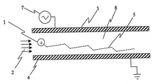
図2aは、FAIMS原理によるイオン分離のメカニズムを示す概略図である。イオン1、例えば、正に荷電されたタイプAのイオンは2つの平行に離間した金属板電極3、4の間を流れる気体流2によって運ばれる。金属板4の1つは、基底状態のポテンシャルに維持され、他の金属板3はV(t)で記述される非対称波形がそこに印加されている。図2bに示すように、その波形の間に印加される極大電圧は分散電圧(DV)と呼ばれる。図2bは、波形が合成されて、時間thighとtlowとの2つの周期の間の電場は等しくない。もしKhとKが高電場と低電場で等しいならば、イオン1は、波形の1周期の最後でもとの位置に戻る。しかしながら、十分に高い電場の条件の下では、KhはKよりも大きくthighとtlowとの間で移動した距離はもはや等しくない。第1と第2の離間した電極金属板3,4の間の空間8によって画定された解析領域内において、それぞれ、イオン1は図2aの破線によって表されるように、金属板3,4に関する当初の位置からの正味のずれにあう。
【0025】
もし、タイプAイオンが上側金属板3から離れるならば、一定の負の補償電圧CVが、逆流またはこの変位移動を「補償」するために金属板3に印加される。もしイオンの2つの種類が、印加された高電場に対して異なるように応答するならば、例えば、Kに対するKhの比が異なるように、金属板への移動を妨げるのに必要な補償電圧は同様に異なる。イオン混合を解析するためには、補償電圧は、例えば、順番に混合の成分の各々を送るように走査される。これは、補償電圧スペクトルまたはCVスペクトルを生む。
【0026】
図3について、先行技術に応じたFAIMS装置は、符号30で概略的に表している。イオン化源(図示せず)で生成されたイオンは、FAIMS解析機34に供給され、FAIMS解析機34は気体引入口35および気体吐出口36を有し、気体引入口35および気体吐出口36は、使用の際に、FAIMS解析機34を通してキャリヤガスの流れを供給するためのものである。キャリヤガスは、例えば、圧縮気体シリンダ37のような外部源から供給される。検出手段(図示せず)、例えば、電位イオン検出機は、また、選択的に移送されたイオンを検出すために設けられている。加えて、電子コントローラ(図示せず)は、分散電圧および補償電圧を印加するために供給してFAIMS解析機34内に、FAIMS原理に基づいてイオンを分離するように電場を生成する。
【0027】
図4において、本発明によるFAIMS装置が概略的に符号40で示されている。イオン化源(図示せず)において生成されたイオンが、FAIMS解析機34に供給される。該FAIMS解析機34は、気体引入口35および気体吐出口36を有し、気体引入口35および気体吐出口36は使用の際にFAIMS解析機34を通してキャリヤガスの流れを供給するためのものである。キャリヤガスは外部源から供給され、例えば、図4において、37a、37bで示される一連の圧縮気体シリンダと接続した気体マニホルド41である。バルブ42a、42b、42cはおのおのシリンダ37a、37b、37cから気体マニホルド41への気体の流れを調節するために提供されている。バルブ42a、42b、42cは手動および電子的の一方で駆動される。もちろん、実際に備えられた圧縮気体シリンダの数は、各システムのユーザーの要求に応じて変更する。希望するならば、圧縮気体シリンダ以外の気体源、例えば、化学反応による気体状生成物を供給するための容器および組織内の気体供給ラインのどちらか一方が、マニホルドと接続される。さらに希望するならば、FAIMS解析機34は、多数の気体引入口をもち、各引入口は、FAIMS解析機34内の混合室(図示せず)への気体の流れを供給するためである。検出手段(図示せず)、例えば、電位イオン検出機は、選択的に移送されたイオンを検出するために設けられている。希望するならば、他の代替のイオン検出手段、例えば、質量分析検出器が用いられる。FAIMS解析機34の配置構造は本発明の操作に決定的なものではない。図4に示されたFAIMS解析機34は、希望するならば、n電極並行金属板FAIMS(n≧2)、湾曲した電極金属板をもつn電極FAIMS(n≧2)、円柱状配置構造のFAIMS装置および半球状端面の円柱状配置構造のFAIMS装置を有するFAIMS解析機のグループから選択される。FAIMS解析機34に課せられた唯一の要件は、電子的コントローラ(図示せず)が分散電圧と補償電圧を、FAIMS原理に基づいて、イオンを分離するために解析機の少なくとも1つに印加することである。
【0028】
操作に際し、イオン化源(図示せず)によってイオンが生成される。イオン化源の性質は、検査の下にあるサンプルに依存して決定される。例えば、電子噴霧のイオン化源からFAIMS解析機34の電源側電極に印加されたDCバイアスおよびキャリヤガスによって、イオンが運ばれる。決定された分散電圧および補償電圧の組合せがFAIMS解析機34の少なくとも1の電極に印加され、そこを通って選択的にイオンを移送するために少なくとも1の電場を生成する。目的とするイオンの分離を達成するために、予め定めた組成のキャリヤガスがFAIMS解析機34の気体引入口35を通って供給される。少なくともキャリヤガスの一部は、印加された非対称波形の少なくとも1周期の間に移送されたイオンが少なくとも1のキャリヤガスの成分と相互作用するように強電場領域を通って振り向けられる。キャリヤガスの組成は、キャリヤガス混合の各成分の、FAIMS解析機34の外部に設けた気体マニホルド41のような混合室へのより適当な流れ率を設定することによって制御される。希望するならば、予め定めた組成をもつキャリヤガスを供給するために、単独の源、例えば、レクチャー・ボトルが直接的に気体引入口35と接続する。選択的に移送されたイオンは適当な検出手段(図示せず)を使用することによって検出される。例えば、電位検出機が使用される。しかし、より好ましくは移送されたイオンを明瞭に識別する質量分析検出システムが使用される。
【0029】
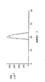
図5a、5b、および図5cには、m/z79およびm/z81の負の電荷を持つ臭素イオンの同位体の3つの補償電圧が示されている。3つのスペクトルは同一の条件の下にあるが、異なるキャリヤガス組成を持つ状態で集められている。図5aのCVスペクトルは、アルゴン気体を用いて集められ、図5bのCVスペクトルは、二酸化炭素ガスを使用して集められ、図5cのCVスペクトルは、アルゴンガスと二酸化炭素ガスとの混合気体を用いて集められたものである。臭素の高電場移動度の従来の知識によると、臭素の高電場移動度は、アルゴンと二酸化炭素の移動度の間の中間に現れるべきである。言い換えれば、臭素イオンは、図5aに示されたものと図5bに示されたもののCVの中間の値のように現れるべきである。アルゴンと二酸化炭素の混合気体を使用して現実に観測されたCVスペクトルは、例えば、図5cに示すように、純粋の気体を使用して観測されたものの中間値とは明らかに異なる。図5cに示された結果は、理論から、または図5aと5bに示されたデータから予想されるものではない。しかしながら、FAIMSの原理の理解は、この現象を説明しかつ異なるキャリヤガスを使用することによって実行された実験と矛盾がない合理的な仮定を可能にする。もちろん、そのような仮定は、提案された説明が正しいものであるという絶対的な確かさの声明としてとらえるべきではない。
【0030】
イオンはFAIMSにおいて、FAIMSの解析領域を横切る高電場または低電場の印加する際にイオンの移動度における差異に基づいて分離される。純粋な、汚染物質のない気体中では、高電場および低電場の移動度はイオンと中性の気体分子との間の衝突の間における相互作用の結果である。結果として、低電場条件に比較して、高電場では、衝突はより力強く、イオンと中性ガスとの間のやや異なる相互作用が現れる。不純物分子を含有する気体中では、その状況はあまり良く定義されない。なぜならば、イオンは一時的で、弱く結合した不純物分子との複合体を形成するだろうからである。一時的な複合体に対する比Kh/Kは、親イオンのそれとは異なるだろう。その結果として、FAIMSでのイオンの振る舞いは、予想がより困難となる。イオンと不純分子との間の複合体が、印加された波形の低電場部分の間に存在するという1つの極端な条件では、その複合体は、波形の高電場部分で乖離するであろう。なぜならば、イオンは、弱く結合した不純分子がイオンから離脱するのに十分なエネルギーをもつ浴用気体を通して引きづられるからである。したがって、波形の各周期では、イオンの移動度には、低電場での複合体として、および高電場での裸のイオンとして、顕著な差異がある。このことは、イオンが現れるCVを高める。これは、わずかな水蒸気のキャリヤガス流への追加の結果として観測される。
【0031】
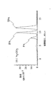
実験は、水蒸気についてよりもむしろ二酸化炭素について容易に実行され、やや大きな、そしてより容易に定量可能な気体の量が使用されることを可能にする。二酸化炭素は、多くのイオンと弱く結合した複合体を形成することが知られている。図6は、負の電荷を持つHSO4 -イオンの、窒素中に0%から100%の二酸化炭素の種々の気体組成を含む一連の実験条件および3つの異なるDVに対するCVの測定実験データの図面を示す。ここで、FAIMS装置は、N1モードで操作されている。例えば、DVの-3,300ボルトでは、HSO4 -イオンは、FAIMSを通して、純粋な窒素では、約22ボルトで、純粋な二酸化炭素では約17ボルトで移送される。窒素中に25%の二酸化炭素で、DVが-3,300ボルトで、HSO4 -の移送は、CVが、22と17ボルトとの間では起こらないことは明らかである。しかし、現実には、約34ボルトで移送される。図6に示すように、DV-2,700およびDV-2,100ボルトの印加に対して同様の結果が示されている。
【0032】
図6に関連して記述されたデータの傾向は、FAIMS装置への非対称波形の印加の間に動力学的な方法で、複合体の形成と解離を考慮して説明される。二酸化炭素を伴うHSO4 -について形成された複合体は非常に弱く結合しているが、複合体の形成率は、例えば、実質的な体積の10%の二酸化炭素成分を持つ気体中で、非常に高い二酸化炭素分子数によって拡大される。低電圧、低電場の非対称波形の部分の印加の間に、HSO4 -と二酸化炭素の間の1または2以上の複合体の形成の傾向がある。上述したように、この弱く結合した複合体は、その際、高電場の波形の間に解離する。なぜならば、イオンの動作は、温度の明らかな上昇に寄与し、そのことは、次々と平衡状態を複合体の解離の方に変移させる。この結び付けられた形成/解離のサイクルは、非対称波形の周期ごとに繰り返され、補償電圧の外見上の値が純粋気体のどちらかで観測されたものに比較して拡大されている。非対称波形を通して印加された電圧上の変化に比較して短い時間枠において平衡状態に到達したという仮定の下で、そのような複合体の形成および破壊の運動は図6に示した結果の理由の説明がもっともらしいことを示唆している。
【0033】
図7は、酸素および窒素中の0%から100%の二酸化炭素の種々の気体組成を持つ一連の実験的条件において、正の電荷を持つCs+イオンの移送に対するCVの絶対値の測定実験データの図を示している。印加されたDVは、300ボルトであり、FAIMSは、P1モードで操作されている。各場合において、キャリヤガスが純粋の二酸化炭素となるまで二酸化炭素が純粋気体に加えられる。明らかに、両方の図形は、純粋な二酸化炭素キャリヤガスとなる図の右側で一致している。この実験は、酸素と窒素の純粋な気体から初めて繰り返される。酸素中に約30%の二酸化炭素の混合気体では、セシウムイオンのCVは約43ボルトである。Cs+イオンの極大の移送は、純粋な酸素での約24ボルト、または、純粋な二酸化炭素での約17ボルトよりも非常に無視できない高いCV値で発生する。図7に示された実験データは、約30%の二酸化炭素の気体組成では、Cs+イオンは、窒素に対して35ボルト近くで移送される。図7の右側の軸で、両者の図が一致している。なぜならば、浴用気体が純粋な100%の二酸化炭素に変更されるからである。
【0034】
図8a、8bおよび8cは、FAIMSを使用することによる解析のための混合気体への適用を示す実験結果を表している。3つの異性体、フタール酸(PA)、イソフタール酸(IPA)およびテレフタール酸(TPA)、であって、各異性体が、約166.2g/molの分子量をもち、各異性体は、電子スプレイイオン化源でイオン化されて、対電荷質量(m/z)が165.2をもつ気相の陽子を除去した分子イオンを生成する。この三つの種類は、質量分析法のみでは分離することはできない。図8aに示すように、テレフタール酸の擬分子イオンが、FAIMSにおける純粋の窒素キャリヤガスをもつESI-FAIMS-MSを使用することによって他の2つの擬分子イオンから分離される。図8aに現れるCVスペクトルは、m/zが-165.2のイオンに対してFAIMSから抽出された移送されたイオンを監視することによって得られる。図8aに現れる標識をつけていない極値は、FAIMSを通して完全な状態で移動するフタール酸イオンを付加させるために寄与する。しかし、質量分析計では、当初のフタール酸のイオンを与えるために付加生成物の損失によって破壊されてm/zが-165.2の破片を生成する。
【0035】
図8bに示されたCVスペクトルは、キャリヤガスが、純粋の二酸化炭素に変更された点を除いて、図8aに関して記述されたものと同一の条件で得られる。図8bは、異なる異性体、フタール酸が、キャリヤガスが純粋の二酸化炭素に変更された際に、他の2つの異性体から分解される。もちろん、純粋気体のいずれか、例えば、窒素または二酸化炭素を使用することによって、FAIMSを用いて、3つの異性体の各々のための別々の極値を決定することは不可能である。好都合なことには、2つの気体の混合、例えば、窒素ガスと二酸化炭素ガスの比が約19:1のものを使用することによって、すべての3つの異性体が、図8cのCVスペクトルについて示したように、容易に分析される。この例は、混合気体の異なる組合せが、FAIMSにおけるイオンの分離に深く非予測的な効果を与えることを示している。FAIMSを用いる異性体分離への可能な応用は、これらの混合気体中におけるイオンの非予測的な振る舞いの発見によって拡大した。
【0036】
図9aおよび図9bは、FAIMSを使用することにより、ペプチドおよびたんぱく質を含むより大きなイオンの分析のための混合気体の適用を表す実験結果を示す。図9aは、FAIMSで純粋の窒素キャリヤガスを使用することによって集め、m/z531を監視することによって、ペプチドのブラディキニンの[M+2H]2+イオンに対して得られたCVスペクトルが示されている。非常に小さな肩状のものが見られるけれども、単独のピークがそのスペクトルを支配している。図9bに表されたCVスペクトルは、FAIMSでのキャリヤガスが、窒素とヘリウムとの混合比が1:1に変化した場合を除いて、同一の条件を使用することによって得られる。このCVスペクトルでは、2つの種類、m/zが531の場合には、別々に分析される。
【0037】
図10aは、図9bのCVスペクトルが、次の議論を容易化するために再現されている。図10bに示した質量スペクトルは、窒素とヘリウムの1:1の混合において、-12.3ボルトのCVで選択的に移送されたイオンに対応する。図10cに示された質量スペクトルは、窒素とヘリウムの1:1混合において、-15.5ボルトのCVで選択的に移送されたイオンに対応する。2つの質量スペクトルはお互いに類似し、CVスペクトルにおける2つのピークがペプチドブラディキニンの[M+2H]2+のイオンの異なる類似物を示している。R.Guevremong, R.Purves およびD.Barnettの名義による同時に係属しているPCT出願に開示されているように、たんぱく質の類似物の分離は、FAIMSを使用することによって達成されるが、FAIMSでの混合気体を使用するブラディキニンの分離は、[M+2H]2+、ブラディキニンイオン、および他のイオンの純粋気体中での振る舞いからは未知でありかつ非予測的である。これらの混合気体がこれらのより大きな種類の分離を改善する理由は、現在知られていないが、混合気体の使用が、FAIMSで、純粋な気体を用いて相互に他の方法では分離できないような類似物の分離に導くことは明らかである。
【0038】
好都合なことには、混合気体の使用が、FAIMSに基づいて、純粋気体の通常の分離によっては不可能な所定イオンの分離に適当である。これは、FAIMS有用性を非常に拡大する。これは、また、例えば、分離を行うための「魔法の弾丸」の探索のような、目的イオンの分離を行うために予想される可能な努力を非常に拡大する。さらに、好都合なことに、本発明により記述されたFAIMSの改良は、既存のFAIMS装置に容易に組み込める。なぜならば、外部の混合室は、希望するならば、混合気体を生成するために提供される。さらに希望するならば、例えば、運搬可能なFAIMS装置を使用する分野での応用において、混合気体は単一のかんによって供給され、かんの気相の内容は、特定の分野の応用に依存して選択された予め定めた組成を有する。
【0039】
当然のなりゆきとして、本発明の教示からあまり離れることなく、多数の他の実施例を想定することができる。
【図面の簡単な説明】
【図1】 電場強度の関数としてイオン移動度における3つの可能な変形例を示す図
【図2a】 電気ポテンシャルV(t)の影響の下での2枚の平行金属板電極間にあるイオンの軌跡を示す図
【図2b】 V(t)によって記述される非対称波形を示す図
【図3】 単一成分のキャリヤガスを用いる先行技術のFAIMS装置を示す図
【図4】 本発明に係る変更可能な組成のキャリヤガスを使用するFAIMS装置を示す図
【図5a】 純粋なアルゴン気体を使用して得られた臭素イオンの例のFAIMSのCVスペクトルを示す図
【図5b】 純粋なアルゴン気体を使用して得られた臭素イオンの例のFAIMSのCVスペクトルを示す図
【図5c】 純粋なアルゴン気体を使用して得られた臭素イオンの例のFAIMSのCVスペクトルを示す図
【図6】 窒素の浴用気体を使用するFAIMSにおける種々のDV電圧でのHSO4 -のCVスペクトルにおける二酸化炭素追加の効果を示す実験データを示す図
【図7】 種々の浴用気体のCs+のCVスペクトルでの二酸化炭素追加の効果を示す実験データを示す図
【図8a】 FAIMSにおいて純粋な窒素の浴用気体を使用してフタル酸(PA)、イソフタル酸(IPA)およびテレフタル酸(TPA)の混合から得られたCVスペクトルを示す図
【図8b】 FAIMSにおいて純粋な二酸化炭素の浴用気体を使用して、フタル酸(PA)、イソフタル酸(IPA)およびテレフタル酸(TPA)の混合から得られたCVスペクトルを示す図
【図8c】 FAIMSにおいて窒素と二酸化炭素の浴用気体の19対1の混合を使用して、フタル酸(PA)、イソフタル酸(IPA)およびテレフタル酸(TPA)の混合から得られたCVスペクトルを示す図
【図9a】 FAIMSにおいて純粋な窒素の浴用気体を使用するペプチドブラジキニンのサンプルから得られたCVスペクトルを示す図
【図9b】 FAIMSにおける窒素とヘリウムの浴用気体の1対1混合を使用したペプチドブラジキニンのサンプルから得られたCVスペクトルを示す図
【図10a】 図9bのCVスペクトルを示す図
【図10b】 図10aの-12.3ボルトCVに相当する選択的に移送されたイオンを解析することにより得られた質量スペクトルを示す図
【図10c】 図10aの-15.5ボルトCVに相当する選択的に移送されたイオンを解析することにより得られた質量スペクトルを示す図
【符号の説明】
1 イオン
2 気体流
3,4 金属板電極
30,40 FAIMS装置
34 FAIMS解析機
35 気体引入口
36 気体吐出口
37 圧縮気体シリンダ[0001]
(Technical field)
The present invention relates to an ion separation apparatus and method, and more particularly, the present invention relates to an ion separation apparatus and method based on the ion focusing principle of a high-field asymmetric waveform ion mobility analysis method (hereinafter referred to as “FAIMS”).
[0002]
(Background technology)
The high sensitivity and sensitivity associated with miniaturization for transportable field applications has led to ion mobility analysis (hereinafter “IMS”) for many compounds, anesthetics, explosives, chemical warfare agents. It helps to make it an important technology for discovery. This point is described, for example, in a book entitled “Ion Mobility Analysis” (CRC, Boca Raton, 1994) by G. Eiceman and Z. Karpas. In IMS, gas phase ion mobility is determined using a drift tube with a constant electric field. Ions are gated into the drift tube and are substantially separated depending on their travel speed differences. The ion transfer rate is proportional to the electric field strength at low electric field strengths. For example, at 200 V / cm, the mobility K determined from experiments is independent of the applied electric field. In addition, in IMS, ions move through a sufficiently high pressure bath gas, and ions reach a constant velocity at high speed by the force of a constant electric field in time and space. This is clearly different from the techniques that are mostly related to mass spectrometry. In these techniques, the gas pressure is sufficiently low so that ions continue to accelerate under the influence of a constant electric field.
[0003]
EAMason and EWMcDaniel are books titled “Ion Transportability in Gases” (Wiley, New York, 1988), and at high electric field strengths, eg, fields above about 5,000 V / cm, ion transfer rates are , Is no longer directly proportional to the applied field, and K becomes dependent on the applied electric field. For high electric field strength, K is a non-constant high electric field mobility term KhIt is appropriate that K to the applied electric fieldhIs the basis for the development of a high field asymmetric waveform ion mobility analysis method (FAIMS), and this term is used in the specification by the inventor to describe the lateral field compensated ion mobility analysis method or field ions. It is also called analysis method. Ions are separated in FAIMS based on differences in ion mobility at high electric field strengths and their mobility KhIs related to the ion mobility K at low electric field strength. In other words, ions are expressed as a function of the applied electric field, KhSeparated for complex dependency behavior. FAIMS provides a new tool for the study of atmospheric gas phases in that it measures changes in ion mobility, not absolute values of ion mobility.
[0004]
The principle of operation of FAIMS using planar electrodes is described by IABuryakove, EVKrylov, EGNararov and U.KH. Rasulev, International Journal of Mass Spectrometry and Ion Processes, Vol. 28. (1993), published in pages 143-148. The mobility of ions given under an electric field is Kh= K (1 + F (E)). Where KhIs the ion mobility at high electric field strength, K is the coefficient of ion mobility at low electric field strength, and F (E) represents the functional dependence of the ion mobility on the electric field. Ions are classified into one of three broad categories based on changes in ion mobility as a function of the strength of the applied electric field. The mobility of type A ions increases with electric field strength, the mobility of type C ions decreases, and the mobility of type B ions first increases before decreasing at higher electric field strengths. The separation of ions in FAIMS is based on changes in mobility at high electric field strengths. Consider the case where ions, for example type A ions, are carried by a gas flow between two spaced parallel metal plate electrodes of a FAIMS device. The space between the metal plates represents an analysis region where ions are separated. The net motion of the ions between the metal plates is the sum of the horizontal x-axis component due to the gas flow and the horizontal y-axis component due to the electric field between the parallel metal plate electrodes. The phrase “net motion” refers to the total translational motion experienced by an ion, eg, the type A ion, even if the translational motion has a faster vibration superimposed thereon. Often, the first metal plate maintains a ground state potential while the second metal plate has an asymmetric waveform, V (t), applied thereon. The asymmetric waveform V (t) is the high-pressure component V1Has time t2After a short period of time, the low-pressure component V of the opposite pole2Has time t1It consists of repeating patterns that last longer. The waveform has an integrated voltage time product applied to the metal plate during the complete period of the waveform and such an electric field-time product is zero. For example, V1 t2+ V2t1For example, = 0 for 2,000 V for 10 μs and then -1,000 V for 20 μs. The shortest maximum voltage, ie, the high voltage portion of the waveform, is referred to as the “distributed voltage” or DV in this disclosure.
[0005]
During the high voltage portion of the waveform, the electric field1= KhEhigh The y-axis velocity component in the horizontal direction is moved. Where EhighIs the applied electric field and KhIs the high field ion mobility under ambient electric field, pressure and temperature conditions. The distance moved is D1= V1t2= KhEhight2And t2Is the time period of the applied high voltage. During the long period of the asymmetric waveform of the low voltage portion having the opposite polarity, the velocity component of the y-axis of the ion is V2= KElowK is the low pressure ion mobility under ambient pressure and temperature conditions. The distance moved is d2= V2t1= KElowt1It is. The asymmetric waveform is (V1t2) + (V2t1) = 0, so electric field-time product Ehight2And Elowt1Are equal in size. In this way, KhD and K are the same1And d2Are equal, and during the period of the negative waveform, the ions return to their original positions along the y-axis. This is expected if both parts of the waveform are low voltage. If EhighAnd mobility is KhIf> K, the ion experiences a net transition from its original position with respect to the y-axis. For example, type A positive ions are farther between the positive positions of the waveform, eg, d1> D2And type A ions move from the second metal plate. Similarly, type C positive ions move toward the second metal plate.
[0006]
If type A positive ions move from the second metal plate, a constant negative DC voltage is applied to the second metal plate to reverse or "compensate" this lateral movement. The This DC voltage is referred to as the “compensation voltage” or CV in this announcement, preventing ions from moving to either the second or first metal plate. If ions derived from two compounds respond differently to the applied high-intensity electric field, K versus KhThe ratio of is different for each compound. In this way, if a mixture containing different types of ions is analyzed by FAIMS, only one type of ions is sent selectively for a given combination of CV and DV. Ions other than the remaining types of ions, for example those selectively sent through FAIMS, move toward one of the parallel metal plate electrodes of FAIMS and are neutralized. Of course, the rate at which the remaining types of ions move toward the FAIMS electrode is of a high electric field mobility that differs from the rate of selectively delivered ions under the general conditions of CV and DV. Dependent.
[0007]
The tool that functions according to the FAIMS principle as described above is an ion filter,hIt is possible to selectively transfer only ions having an appropriate ratio. In one type of experiment using FAIMS, the applied CV is scanned by time, for example, the CV is slowly ramped or, if desired, the CV is changed from one voltage value to the next and transferred. The intensity results of the ions are measured. In this way, a CV spectrum showing the total ion flow as a function of CV is obtained. The identity of the extreme values appearing in the CV spectrum is different from that clearly determined only on the basis of the CV for the transfer of one type of ion. This is a serious limitation. This limit is the K in electric field strength.hThis is due to the unpredictable compound-property dependence. In other words, the extreme values in the CV spectrum are easily mistakenly assigned to one compound. This is because, for example, from the structure of an ion, there is no way to predict or evaluate in advance where the ion should appear in the CV spectrum. In other words, additional information is needed to improve the likelihood of correctly assigning extreme values in the CV spectrum. For example, subsequent mass spectrometric analysis of selectively transferred ions greatly enhances the accuracy of specifying extreme values in the CV spectrum.
[0008]
In US Pat. No. 5,420,424, issued May 30, 1995, BLCarnahan and AStarassove disclose an improved FAIMS electrode arrangement, in which a flat metal plate used for ion separation in the arrangement is It is replaced by a concentric cylinder, and the content of the arrangement structure is quoted here. The concentric cylinder design has several advantages, including higher sensitivity compared to a flat metal plate arrangement. This was published by RWPurves, R. Gueveremont, S. Day, CWPipich and MSMaryjaszczyk in Review of Scientific Instruments, Volume 69 (1998) 4094-4105. Discussed in the paper. The high sensitivity of the cylindrical FAIMS is based on the two-dimensional atmospheric pressure ion focus effect generated in the analysis region between concentric cylindrical electrodes. When no voltage is applied to the cylinder, the radial distribution of ions is substantially uniform across the FAIMS analyzer. However, during the application of DV and CV, the radial ion distribution is not uniform throughout the annular space of the FAIMS analysis region. Conveniently, application of appropriate DV and CV to the target ions will cause these ions to focus in the zone between the electrodes, reducing the rate of ion loss as a result of collisions with the FAIMS electrode. be able to. The efficiency of transport of the target ions through the FAIMS analysis region is enhanced as a result of this two-dimensional focus effect.
[0009]
So far, ion focusing by using asymmetric waveforms has been discussed. For the sake of completeness, the behavior of ions that are not focused within the analysis region of the FAIMS with a cylindrical arrangement is briefly described here. As previously discussed, ions having high field ion mobility that are not suitable for focusing under a given set of DV and CV and configuration conditions are one or other walls of the FAIMS device. Will move towards the department. The speed at which these ions move toward the wall is different from the speed of the selectively transferred ions under the conditions described above.hDepends on the degree of / K. In extreme cases, ions with completely unfavorable properties, for example type A ions, disappear very quickly at the wall of the FAIMS device compared to type C ions.
[0010]
The disappearance of ions in the FAIMS device should be considered in another way. For example, with a given configuration, if a type A ion is focused with a 2,500 volt DV and a -11 volt CV, for example, a DV and CV of -2,500 volt DV and a +11 volt CV. As the polarity reverses, it would seem reasonable to expect the ions to focus again. However, this is not observed, and in fact polarity reversal in this manner creates the mirror effect of the FAIMS ion focusing operation. The result of this polarity reversal is that the ions are not focused but rather removed from the device very quickly. The mirror image of the focused valley is a mountain-shaped potential surface. Ions travel to slide to the center of the focused potential valley (2 or 3 dimensions). However, it slides away from the top of the mountain-shaped surface and strikes the electrode wall. This is the reason for the existence in the columnar FAIMS of independent modes called 1 and 2. Such a FAIMS device is operated in one of four possible modes P1, P2, N1 and N2. “P” and “N” describe the polarity of the ions, positive (P) and negative (N). If DV represents the extreme value of the voltage in the high voltage portion of the asymmetric waveform, a waveform with a positive DV yields a spectrum of types P1 and N2, and a DV waveform with an inverted negative polarity yields P2 and N1. . The discussion so far has considered positive ions, but in general the same principles apply equally to negative ions.
[0011]
Further improvements to the cylindrical FAIMS design have been realized by providing an end with a curved surface of the internal electrode. The end portion having the curved surface is continuous with the cylindrical shape of the internal electrode and is arranged coaxially with the ion ejection port in the FAIMS analysis region. Application of an asymmetric waveform to the internal electrode results in the normal ion focusing operation described above, except that it extends around the generally spherical end of the internal electrode. This means that selectively transferred ions cannot escape from the area around the edge of the internal electrode. This only occurs if the voltage applied to the internal electrode is an appropriate combination of CV and DV as described in the discussion above in connection with two-dimensional focusing. If CV and DV are suitable for ion focusing in the FAIMS analysis region and the physical arrangement of the inner surface of the outer electrode does not disturb this balance, the ion is in the three-dimensional vicinity of the edge. Will focus in the domain space. Several reaction forces act on ions in this region near the edge of the internal electrode. The force due to the flow of the carrier gas tends to affect the ion cloud moving toward the ion outlet. Conveniently, this prevents the trapped ions from moving in the reverse direction, i.e. returning to the ionization source. In addition, due to the focusing action of the applied electric field, ions that are too close to the internal electrode are pushed back away from the internal electrode, and ions near the external electrode return toward the internal electrode. When the total force acting on the ions is balanced, the ions are efficiently trapped in all directions by the force of the flowing gas or by the focusing effect of the electric field of the FAIMS. This is an example of three-dimensional atmospheric pressure ion capture, as disclosed in the pending PCT application in the name of R.Guvremont and R.Gueveremont and R.Purves, the contents of which are hereby incorporated by reference.
[0012]
Ion focusing and ion trapping occur other than spatially constant, usually in FAIMS geometries where the electrodes are bent and / or not parallel to each other. For example, a spatially non-constant electric field is generated by using a cylinder or part thereof, a spherical electrode or part thereof, a conical electrode or part thereof. Optionally, various combinations of these electrode shapes are used.
[0013]
As discussed above, one conventional limitation of the cylindrical FAIMS technique is that the extreme values appearing in the CV spectrum are the K at high field strength.hVaguely confirmed due to unpredictable changes in Thus, one way to expand the capabilities of a device based on the FAIMS concept is to assemble the CV spectrum to introduce ions from the FAIMS device into a mass spectrometer for counter-charge mass (m / z) analysis. It is to provide a method for more accurately determining. Conveniently, the ion focusability of the cylindrical FAIMS device operates to increase the efficiency for transferring ions from the analysis region of the FAIMS to an external sample hole, such as a mass spectrometer inlet. The improved efficiency for transferring ions to the mass spectrometer inlet is optionally maximized by using a three-dimensional capture version of FAIMS operated at approximately capture conditions. Under almost trapping conditions, ions gathered in a three-dimensional region in the space near the spherical end of the internal electrode are attracted by the flow toward the hole of the ion discharge port and leak out of this region. Ions leaking from this region will be attracted by a gas stream that leaks like a narrow, generally collimated beam and travels through a small hole that leads through the ion outlet to the vacuum system of the mass spectrometer.
[0014]
In addition, the resolution of the FAIMS device is defined by an expression representing the degree to which ions having mobility similar to the electric field strength function are separated under a set of predetermined operating conditions. Thus, a high resolution FAIMS device selectively transports relatively small regions of different ion types with similar mobility, whereas a low resolution FAIMS device has different ion types with similar mobility. Transfer relatively large areas. The resolution of FAIMS in the columnar arrangement structure FAIMS is inferior to the resolution in FAIMS of the parallel metal plate arrangement structure. This is because FAIMS having a cylindrical arrangement structure has an ability to focus ions. This focusing operation means that ions in a wide mobility range are simultaneously focused on the analysis region of the FAIMS having a cylindrical arrangement structure. A columnar arrangement of FAIMS with narrow electrodes has the strongest focusing action but the lowest resolution for ion separation. As the radius of curvature increases, the focusing action weakens and the ability of FAIMS to simultaneously focus ions with similar high field mobility decreases simultaneously. This means that as the radius of curvature increases, the resolution of FAIMS increases, and the FAIMS of the parallel metal plate arrangement has the maximum resolution that can be reached.
[0015]
Although the above discussion refers to ions that are “captured” or “damped”, it should be noted that in fact ions undergo continuous “diffusion”. Diffusion always works counter to focusing and capture. Ions always require electrical or gas flow forces to back flow into the diffusion process. Thus, although the ions are focused in a space with almost zero thickness or in an imaginary cylindrical area within the pitfalls of a three-dimensional ion, in reality, the ions are idealized in space due to diffusion. It is well known that it is distributed near the area. This is important and should be recognized as a gross feature overlaid on all of the ion mobility discussed in this specification. This is due to several physicochemical reasons, for example, three-dimensional ion damming actually has a realistic space width, and ions continuously leak out of the three-dimensional ion damming. Of course, ions occupy a small physical area in space if the damming potential well becomes deeper.
[0016]
The published scientific literature quoted on ion behavior in high electric fields shows that the behavior of certain ions in a mixture of two gases is that E is the electric field strength and N is the number density of the gas. It reveals what is expected from the behavior of ions in two gases, each in a pure state. This is consistent with the theory of ion mobility and the theory of gas motion. At high E / N, the effective temperature of the ions in each pure gas is slightly different, resulting in a small deviation from this predicted value. This is because ions can only experience a finite effective temperature of 1 in the gas mixture. These adjustments are discussed by Viehkand and Mason (At. Data, Nucl. Data Tables 60, 37 (1995) and 21,113, (1984) and 17, 177 (1976)). These modifications to the ideal behavior are small.
[0017]
Prior art FAIMS devices typically use a carrier gas consisting of one purified stream of nitrogen, oxygen and air. However, recent experimental studies on FAIMS point out that in some cases there is a very significant deviation from the expected apparent behavior of ions in the gas mixture. These deviations have a significant meaning for the application of FAIMS. This is because in some cases the use of a gas mixture weakens the separation of certain ions. Here, the usual selection of pure gas is not possible. It would be beneficial to provide a method and apparatus for extending the ion separation capabilities of a FAIMS apparatus that uses a carrier gas stream having a tunable mixed composition.
[0018]
(Problems to be solved by the invention)
In order to overcome these and other limitations of the prior art, it is an object of the present invention to provide a high field ion mobility analyzer supplied by a carrier gas source having various well known compositions. .
[0019]
To overcome these and other limitations of the prior art, high field ion mobility analysis such that the composition of the carrier gas can be adjusted by adding at least one second different gas to the initial carrier gas. Is to provide a device.
[0020]
(Means for solving the problem)
In accordance with the present invention, two electrodes provide an electric field resulting from the application of an asymmetric waveform to at least one electrode to affect ion mobility and allow at least one gas to pass between the electrodes. And an analysis region having at least one gas inlet, wherein the gas inlet is for introducing a first gas and a second different gas into the analysis region. An ion separation apparatus having a high electric field asymmetric waveform ion mobility analyzer for supplying a predetermined mixed gas into the analysis region by a gas and a second different gas.
[0021]
In accordance with the present invention, two electrodes provide an electric field resulting from the application of an asymmetric waveform to at least one electrode to affect ion mobility and allow at least one gas to pass between the electrodes. A first gas inlet that communicates with the first gas source and receives a first gas flow, and a second gas inlet that communicates with a second gas source and receives a second different gas flow And a high electric field asymmetric waveform ion mobility analyzer that mixes the gas passing through the first gas inlet with the gas passing through the second gas inlet in use. It is an ion separation device.
[0022]
According to the invention, a) providing two electrodes having a first electrode and a second electrode,
b) supplying an asymmetric waveform and a dc compensation voltage to at least one of the two electrodes to form an electric field therebetween, such that the electric field causes separation of ions by forming a subset thereof; In order to produce a net displacement difference between ions within a period of the applied asymmetric waveform,
c) supplying a stream of carrier gas having a predetermined composition containing at least two different chemical components through an electric field;
d) An ion separation method comprising steps of moving through the electric field in a direction substantially transverse to the electric field, wherein the two different chemical components are linked with the electric field to cause ion separation.
[0023]
(Embodiment of the Invention)
FIG. 1 shows three possible examples of changes in ion mobility as the electric field strength is increased as previously discussed. The separation of ions in FAIMS is based on the difference in mobility of the first ion relative to the second ion. For example, if under the influence of high electric field strength, K1, high/ K1, lowK2, high / K2, lowLow field mobility K1, lowThe first type A ion with a second different low field mobility K2, lowIs not separated in the FAIMS apparatus from second type A ions with Interestingly, however, this same separation is achieved using conventional ion mobility analyzers based on differences in ion mobility at the applied low field strength.
[0024]
FIG. 2a is a schematic diagram showing the mechanism of ion separation according to the FAIMS principle.
[0025]
If type A ions leave the upper metal plate 3, a constant negative compensation voltage CV is applied to the metal plate 3 to "compensate" backflow or this displacement movement. If the two types of ions respond differently to the applied high electric field, for example, K to KhThe compensation voltage required to prevent movement to the metal plate is different as well, so that the ratios of the two are different. To analyze ion mixing, the compensation voltage is scanned, for example, to send each of the components of the mixture in turn. This yields a compensation voltage spectrum or CV spectrum.
[0026]
With reference to FIG. 3, the FAIMS device according to the prior art is schematically represented by the
[0027]
In FIG. 4, a FAIMS device according to the present invention is schematically indicated at 40. Ions generated in an ionization source (not shown) are supplied to the
[0028]
In operation, ions are generated by an ionization source (not shown). The nature of the ionization source is determined depending on the sample under examination. For example, ions are carried by a DC bias and carrier gas applied to the power supply side electrode of the
[0029]
FIGS. 5a, 5b, and 5c show three compensation voltages for isotopes of bromide ions with negative charges of m / z79 and m / z81. The three spectra are collected under the same conditions but with different carrier gas compositions. The CV spectrum of FIG. 5a is collected using argon gas, the CV spectrum of FIG. 5b is collected using carbon dioxide gas, and the CV spectrum of FIG. 5c is a mixture of argon gas and carbon dioxide gas. It was collected using. According to conventional knowledge of bromine high field mobility, bromine high field mobility should appear intermediate between the mobility of argon and carbon dioxide. In other words, bromine ions should appear as intermediate values of CV between those shown in FIG. 5a and those shown in FIG. 5b. The CV spectrum actually observed using a mixed gas of argon and carbon dioxide is clearly different from the intermediate value observed with a pure gas, for example, as shown in FIG. 5c. The results shown in FIG. 5c are not expected from theory or from the data shown in FIGS. 5a and 5b. However, an understanding of the principles of FAIMS allows rational assumptions that explain this phenomenon and are consistent with experiments performed by using different carrier gases. Of course, such an assumption should not be taken as a statement of absolute certainty that the proposed explanation is correct.
[0030]
Ions are separated in FAIMS based on differences in ion mobility when a high or low electric field is applied across the FAIMS analysis region. In a pure, contaminant-free gas, the high and low field mobilities are the result of interactions during collisions between ions and neutral gas molecules. As a result, compared to low electric field conditions, collisions are stronger at high electric fields and a slightly different interaction between ions and neutral gas appears. In gases containing impurity molecules, the situation is not well defined. This is because ions will be temporary and will form a complex with weakly bound impurity molecules. Ratio K to transient complexh/ K will be different from that of the parent ion. As a result, the behavior of ions in FAIMS is more difficult to predict. In one extreme condition where a complex between an ion and an impure molecule exists between the low field portions of the applied waveform, the complex will diverge in the high field portion of the waveform. This is because ions are attracted through a bathing gas with sufficient energy for weakly bound impurity molecules to leave the ion. Thus, at each period of the waveform, there is a significant difference in ion mobility as a complex at low electric fields and as a bare ion at high electric fields. This increases the CV at which ions appear. This is observed as a result of the addition of a small amount of water vapor to the carrier gas stream.
[0031]
The experiment is easily performed on carbon dioxide rather than on water vapor, allowing a somewhat larger and more easily quantifiable amount of gas to be used. Carbon dioxide is known to form weakly bound complexes with many ions. Figure 6 shows HSO with negative chargeFour -FIG. 2 shows a drawing of a series of experimental conditions including various gas compositions of 0% to 100% carbon dioxide in nitrogen and CV measurement experimental data for three different DVs. Here, the FAIMS device is operated in N1 mode. For example, at -3300 volts DV, HSOFour -Ions are transported through FAIMS at about 22 volts for pure nitrogen and about 17 volts for pure carbon dioxide. 25% carbon dioxide in nitrogen, DV -3,300 volts, HSOFour -It is clear that CV does not occur between 22 and 17 volts. However, in reality, it is transported at about 34 volts. As shown in FIG. 6, similar results are shown for the application of DV-2,700 and DV-2,100 volts.
[0032]
The data trends described in connection with FIG. 6 are explained in a kinetic manner, taking into account the formation and dissociation of the complex during the application of the asymmetric waveform to the FAIMS device. HSO with carbon dioxideFour -The complex formed for is bound very weakly, but the rate of formation of the complex is, for example, due to the very high number of carbon dioxide molecules in a gas with a substantial volume of carbon dioxide component of 10%. Enlarged. During the application of the low voltage, low electric field asymmetric waveform part, HSOFour -There is a tendency for the formation of one or more complexes between and carbon dioxide. As mentioned above, this weakly bound complex then dissociates between the waveforms of the high electric field. Because the action of ions contributes to a clear increase in temperature, which in turn shifts the equilibrium state towards the dissociation of the complex. This coupled formation / dissociation cycle is repeated for each period of the asymmetric waveform, expanding the apparent value of the compensation voltage compared to that observed for either pure gas. Under the assumption that equilibrium was reached in a short time frame compared to the change in voltage applied through the asymmetric waveform, the formation and breakdown movement of such a complex is the reason for the results shown in FIG. The explanation suggests that it is plausible.
[0033]
FIG. 7 shows positively charged Cs in a series of experimental conditions with various gas compositions of 0% to 100% carbon dioxide in oxygen and nitrogen.+CV for ion transferAbsolute valueThe figure of measurement experiment data is shown. The applied DV is 300 volts and the FAIMS is operated in P1 mode. In each case, carbon dioxide is added to the pure gas until the carrier gas is pure carbon dioxide. Obviously, both figures coincide on the right side of the diagram, which is a pure carbon dioxide carrier gas. This experiment is repeated for the first time from pure oxygen and nitrogen gases. In a gas mixture of about 30% carbon dioxide in oxygen, the CV of cesium ions is about 43 volts. Cs+The maximal transport of ions occurs at high CV values that are much more negligible than about 24 volts with pure oxygen or about 17 volts with pure carbon dioxide. The experimental data shown in FIG. 7 shows that for a gas composition of about 30% carbon dioxide, Cs+Ions are transported near 35 volts relative to nitrogen. In the right axis of FIG. 7, both figures are in agreement. This is because the bath gas is changed to pure 100% carbon dioxide.
[0034]
Figures 8a, 8b and 8c represent experimental results showing application to gas mixtures for analysis by using FAIMS. Three isomers, phthalic acid (PA), isophthalic acid (IPA) and terephthalic acid (TPA), each isomer having a molecular weight of about 166.2 g / mol, each isomer being electron spray ionized It is ionized at the source to produce molecular ions that have removed protons in the gas phase with a counter charge mass (m / z) of 165.2. These three types cannot be separated by mass spectrometry alone. As shown in FIG. 8a, the terephthalic acid quasimolecular ion is separated from the other two quasimolecular ions by using ESI-FAIMS-MS with pure nitrogen carrier gas in FAIMS. The CV spectrum appearing in FIG. 8a is obtained by monitoring the transported ions extracted from FAIMS for ions with m / z -165.2. The unlabeled extreme value appearing in FIG. 8a contributes to the addition of phthalate ions that migrate in their entirety through FAIMS. However, in the mass spectrometer, it is broken by the loss of adduct to give the original phthalic acid ions, producing fragments with m / z -165.2.
[0035]
The CV spectrum shown in FIG. 8b is obtained under the same conditions as described with respect to FIG. 8a, except that the carrier gas has been changed to pure carbon dioxide. FIG. 8b shows that a different isomer, phthalic acid, is decomposed from the other two isomers when the carrier gas is changed to pure carbon dioxide. Of course, it is not possible to determine separate extreme values for each of the three isomers using FAIMS by using any of the pure gases, such as nitrogen or carbon dioxide. Conveniently, by using a mixture of two gases, eg, a ratio of nitrogen gas to carbon dioxide gas of about 19: 1, all three isomers are shown for the CV spectrum of FIG. 8c. As such, it is easily analyzed. This example shows that different combinations of gas mixtures have a deep and unpredictable effect on the separation of ions in FAIMS. Possible applications for isomer separation using FAIMS have been expanded by the discovery of unpredictable behavior of ions in these gas mixtures.
[0036]
Figures 9a and 9b show experimental results representing the application of gas mixtures for the analysis of larger ions containing peptides and proteins by using FAIMS. FIG. 9a is collected by using pure nitrogen carrier gas in FAIMS and monitoring the m /
[0037]
FIG. 10a is a reproduction of the CV spectrum of FIG. 9b to facilitate the following discussion. The mass spectrum shown in FIG. 10b corresponds to ions selectively transferred at a CV of −12.3 volts in a 1: 1 mixture of nitrogen and helium. The mass spectrum shown in FIG. 10c corresponds to ions selectively transferred at a CV of -15.5 volts in a 1: 1 mixture of nitrogen and helium. The two mass spectra are similar to each other, and the two peaks in the CV spectrum are the [M + 2H] of peptide bradykinin2+The different analogs of the ions are shown. As disclosed in the co-pending PCT application in the name of R. Guevremong, R. Purves and D. Barnett, separation of protein analogs is achieved by using FAIMS, but in FAIMS Of bradykinin using a mixed gas of [M + 2H]2+It is unknown and unpredictable from the behavior of bradykinin ions and other ions in pure gas. The reasons why these gas mixtures improve these larger types of separation are not currently known, but the use of gas mixtures is not possible with FAIMS in any other way with pure gas. Clearly it leads to the separation of analogues.
[0038]
Conveniently, the use of a gas mixture is suitable for the separation of certain ions, based on FAIMS, which is not possible by the usual separation of pure gases. This greatly expands the FAIMS utility. This also greatly expands the possible efforts expected to perform the separation of the target ions, such as searching for “magic bullets” to perform the separation. Furthermore, advantageously, the FAIMS improvements described by the present invention can be easily incorporated into existing FAIMS devices. This is because an external mixing chamber is provided to produce a gas mixture if desired. If further desired, for example in applications in the field using transportable FAIMS devices, the gas mixture is supplied by a single can, and the gas phase content of the can depends on the application in the particular field. Having a selected predetermined composition.
[0039]
Naturally, numerous other embodiments can be envisaged without departing significantly from the teachings of the present invention.
[Brief description of the drawings]
FIG. 1 shows three possible variations in ion mobility as a function of electric field strength.
FIG. 2a shows a trajectory of ions between two parallel metal plate electrodes under the influence of electric potential V (t).
FIG. 2b shows an asymmetric waveform described by V (t)
FIG. 3 shows a prior art FAIMS device using a single component carrier gas.
FIG. 4 shows a FAIMS device using a carrier gas of variable composition according to the present invention.
FIG. 5a shows the FAIMS CV spectrum of an example bromine ion obtained using pure argon gas.
FIG. 5b shows the FAIMS CV spectrum of an example bromine ion obtained using pure argon gas.
FIG. 5c shows the FAMS CV spectrum of an example bromine ion obtained using pure argon gas.
FIG. 6: HSO at various DV voltages in FAIMS using nitrogen bath gas.Four -The figure which shows the experimental data which show the effect of the carbon dioxide addition in the CV spectrum of
FIG. 7 Cs of various bath gases+The figure which shows the experimental data which show the effect of the carbon dioxide addition in the CV spectrum of
FIG. 8a shows a CV spectrum obtained from a mixture of phthalic acid (PA), isophthalic acid (IPA) and terephthalic acid (TPA) using a pure nitrogen bath gas in FAIMS.
FIG. 8b shows a CV spectrum obtained from a mixture of phthalic acid (PA), isophthalic acid (IPA) and terephthalic acid (TPA) using a pure carbon dioxide bath gas in FAIMS.
FIG. 8c shows a CV spectrum obtained from a mixture of phthalic acid (PA), isophthalic acid (IPA) and terephthalic acid (TPA) using a 19: 1 mixture of nitrogen and carbon dioxide bath gases in FAIMS. Illustration
FIG. 9a shows a CV spectrum obtained from a sample of peptide bradykinin using pure nitrogen bath gas in FAIMS.
FIG. 9b shows a CV spectrum obtained from a sample of peptide bradykinin using a 1: 1 mixture of nitrogen and helium bath gases in FAIMS.
FIG. 10a shows the CV spectrum of FIG. 9b.
10b shows a mass spectrum obtained by analyzing selectively transferred ions corresponding to the −12.3 volt CV of FIG. 10a.
10c shows a mass spectrum obtained by analyzing selectively transferred ions corresponding to -15.5 volts CV in FIG. 10a.
[Explanation of symbols]
1 ion
2 Gas flow
3,4 metal plate electrode
30, 40 FAIMS equipment
34 FAIMS analyzer
35 Gas inlet
36 Gas outlet
37 Compressed gas cylinder
Claims (22)
b)非対称波形および直流補償電圧を、2つの電極のうちの少なくとも1つに供給して、電極間に電場を形成し、その電場は、その部分集合を形成することによってイオンの分離を生ずるように印加された非対称波形の1周期の時間内にイオン間に正味の変位の差異を生ぜしめるためであり、
c)空気と同一の組成以外の少なくとも2つの異なる化学成分を含有する予め定めた組成を有するキャリヤガスの流れを電場を通して供給し、
d)電場を横切る方向に電場を通って移送する各工程を有するとともに、
前記2つの異なる化学成分は電場と連動して、イオンの分離を生ずるイオン分離方法。a) providing two electrodes having a first electrode and a second electrode;
b) Supplying an asymmetric waveform and a DC compensation voltage to at least one of the two electrodes to form an electric field between the electrodes, such that the electric field causes separation of ions by forming a subset thereof. To produce a net displacement difference between ions within one period of the asymmetric waveform applied to
c) fed through an electric field to a carrier gas stream having a predetermined composition comprising at least two different chemical components other than the composition of the air and the same,
together with the steps of transferring through an electric field in a direction to cut sideways d) electric field,
An ion separation method in which the two different chemical components work together with an electric field to cause separation of ions.
b2)選択的に移送されたイオンに対する補償電圧の走査を生み出すために、補償電圧を変更し、かつ、生じている選択的に移送されたイオンを測定し、
b3)純粋のキャリヤガス内での同一の高電場移動度の性質をもつイオンの分離を生ずるようにキャリヤガス組成を決定する各工程を前記工程c)の前に有する請求項9に記載の方法。b1) changing the carrier gas composition;
b2) changing the compensation voltage to produce a scan of the compensation voltage for selectively transported ions and measuring the resulting selectively transported ions;
Each step of determining a carrier gas composition to produce a separation of the ions having the same properties of high field mobility within b3) pure carrier gas according to claim 9 having before said step c) Method.
b)非対称波形で直流の補償電圧を、その間に電場を形成する2つの電極の少なくとも一方に供給し、その電場は、それの部分集合を形成することによって、イオンの分離を生じるように印加された非対称波形の1周期の時間内にイオンの間の正味の変位における差異を生じさせるものであり、
c)前記電場を通して第1のキャリヤガスの流れを供給し、
d)第2の異なる気体を第1の気体の流れに加えて、前記電場を通って、混合キャリヤガスを供給し、その混合気体は電場を通って前記イオンを運ぶものであり、
e)第1のキャリヤガスおよび第2のキャリヤガスのどちらか一方の流れ内に同一の高電場移動性をもち異なるイオンを含有するイオンの分離をもたらすために混合されたキャリヤガス組成を決定し、
f)前記電場を横切る方向に、電場を通ってイオンを運ぶ工程を有するイオン分離方法。a) providing two electrodes having a first electrode and a second electrode;
b) Supplying a DC compensation voltage in an asymmetric waveform to at least one of the two electrodes forming an electric field therebetween, the electric field being applied to form an ion separation by forming a subset thereof. A difference in the net displacement between ions within one cycle of the asymmetric waveform,
c) supplying a first carrier gas stream through the electric field;
d) adding a second different gas to the first gas stream and supplying a mixed carrier gas through the electric field, the mixed gas carrying the ions through the electric field;
determining a carrier gas composition mixed to effect separation of ions containing having different ion same high field mobility either within the one flow of e) the first carrier gas and the second carrier gas And
f) in the direction of cutting transverse the electric field, the ion separation method having a step of carrying ions through an electric field.
Applications Claiming Priority (3)
| Application Number | Priority Date | Filing Date | Title |
|---|---|---|---|
| US18908500P | 2000-03-14 | 2000-03-14 | |
| US60/189,085 | 2000-03-14 | ||
| PCT/CA2001/000310 WO2001069646A2 (en) | 2000-03-14 | 2001-03-14 | Faims apparatus and method using carrier gas of mixed composition |
Publications (3)
| Publication Number | Publication Date |
|---|---|
| JP2003527734A JP2003527734A (en) | 2003-09-16 |
| JP2003527734A5 JP2003527734A5 (en) | 2011-06-16 |
| JP4783533B2 true JP4783533B2 (en) | 2011-09-28 |
Family
ID=22695859
Family Applications (1)
| Application Number | Title | Priority Date | Filing Date |
|---|---|---|---|
| JP2001567612A Expired - Fee Related JP4783533B2 (en) | 2000-03-14 | 2001-03-14 | FAIMS apparatus and method using carrier gas of mixed composition |
Country Status (8)
| Country | Link |
|---|---|
| US (6) | US6653627B2 (en) |
| EP (4) | EP1266395A2 (en) |
| JP (1) | JP4783533B2 (en) |
| AT (2) | ATE308115T1 (en) |
| AU (10) | AU3907301A (en) |
| CA (6) | CA2402798C (en) |
| DE (2) | DE60114394T2 (en) |
| WO (6) | WO2001069646A2 (en) |
Families Citing this family (144)
| Publication number | Priority date | Publication date | Assignee | Title |
|---|---|---|---|---|
| US7157700B2 (en) * | 2001-06-30 | 2007-01-02 | Sionex Corporation | System for collection of data and identification of unknown ion species in an electric field |
| US6690004B2 (en) | 1999-07-21 | 2004-02-10 | The Charles Stark Draper Laboratory, Inc. | Method and apparatus for electrospray-augmented high field asymmetric ion mobility spectrometry |
| US6806463B2 (en) * | 1999-07-21 | 2004-10-19 | The Charles Stark Draper Laboratory, Inc. | Micromachined field asymmetric ion mobility filter and detection system |
| US7129482B2 (en) | 1999-07-21 | 2006-10-31 | Sionex Corporation | Explosives detection using differential ion mobility spectrometry |
| US7005632B2 (en) * | 2002-04-12 | 2006-02-28 | Sionex Corporation | Method and apparatus for control of mobility-based ion species identification |
| US6815668B2 (en) * | 1999-07-21 | 2004-11-09 | The Charles Stark Draper Laboratory, Inc. | Method and apparatus for chromatography-high field asymmetric waveform ion mobility spectrometry |
| US7399958B2 (en) * | 1999-07-21 | 2008-07-15 | Sionex Corporation | Method and apparatus for enhanced ion mobility based sample analysis using various analyzer configurations |
| US6815669B1 (en) | 1999-07-21 | 2004-11-09 | The Charles Stark Draper Laboratory, Inc. | Longitudinal field driven ion mobility filter and detection system |
| US7148477B2 (en) * | 1999-07-21 | 2006-12-12 | Sionex Corporation | System for trajectory-based ion species identification |
| US7098449B1 (en) | 1999-07-21 | 2006-08-29 | The Charles Stark Draper Laboratory, Inc. | Spectrometer chip assembly |
| US7057168B2 (en) * | 1999-07-21 | 2006-06-06 | Sionex Corporation | Systems for differential ion mobility analysis |
| CA2401772C (en) * | 2000-03-14 | 2009-11-24 | National Research Council Of Canada | Tandem high field asymmetric waveform ion mobility spectrometry (faims)/ion mobility spectrometry |
| WO2001069216A2 (en) * | 2000-03-14 | 2001-09-20 | National Research Council Canada | Improved parallel plate geometry faims apparatus and method |
| US6653627B2 (en) | 2000-03-14 | 2003-11-25 | National Research Council Canada | FAIMS apparatus and method with laser-based ionization source |
| WO2001095999A1 (en) * | 2000-06-09 | 2001-12-20 | University Of Delaware | System and method for chemical analysis using laser ablation |
| AU2002257177B2 (en) * | 2001-04-17 | 2004-11-25 | The Charles Stark Draper Laboratory, Inc. | Methods and apparatus for electrospray-augmented high field asymmetric ion mobility spectrometry |
| US7586088B2 (en) | 2001-06-21 | 2009-09-08 | Micromass Uk Limited | Mass spectrometer and method of mass spectrometry |
| EP1405065B1 (en) * | 2001-06-30 | 2012-04-11 | Dh Technologies Development Pte. Ltd. | System for collection of data and identification of unknown ion species in an electric field |
| US7119328B2 (en) * | 2001-06-30 | 2006-10-10 | Sionex Corporation | System for DMS peak resolution |
| US7091481B2 (en) | 2001-08-08 | 2006-08-15 | Sionex Corporation | Method and apparatus for plasma generation |
| US7274015B2 (en) * | 2001-08-08 | 2007-09-25 | Sionex Corporation | Capacitive discharge plasma ion source |
| US6727496B2 (en) * | 2001-08-14 | 2004-04-27 | Sionex Corporation | Pancake spectrometer |
| WO2003044526A1 (en) * | 2001-11-16 | 2003-05-30 | Waters Investments Limited | Parallel concentration, desalting and deposition onto maldi targets |
| US6998608B2 (en) * | 2002-02-08 | 2006-02-14 | Ionalytics Corporation | FAIMS with non-destructive detection of selectively transmitted ions |
| US7005633B2 (en) * | 2002-02-08 | 2006-02-28 | Ionalytics Corporation | Method and apparatus for desolvating ions for introduction into a FAIMS analyzer region |
| US7223967B2 (en) * | 2002-02-08 | 2007-05-29 | Thermo Finnigan Llc | Side-to-side FAIMS apparatus having an analyzer region with non-uniform spacing and method therefore |
| US7026612B2 (en) * | 2002-02-08 | 2006-04-11 | Ionalytics Corporation | FAIMS apparatus and method using carrier gases that contain a trace amount of a dopant species |
| US6987262B2 (en) * | 2002-02-08 | 2006-01-17 | Ionalytics Corporation | FAIMS apparatus and method for detecting trace amounts of a vapour in a carrier gas |
| US7034286B2 (en) | 2002-02-08 | 2006-04-25 | Ionalytics Corporation | FAIMS apparatus having plural ion inlets and method therefore |
| US7122794B1 (en) | 2002-02-21 | 2006-10-17 | Sionex Corporation | Systems and methods for ion mobility control |
| FI118277B (en) | 2002-03-25 | 2007-09-14 | Environics Oy | Cell structure, instruments and method |
| US6906319B2 (en) | 2002-05-17 | 2005-06-14 | Micromass Uk Limited | Mass spectrometer |
| DE10236344B4 (en) * | 2002-08-08 | 2007-03-29 | Bruker Daltonik Gmbh | Ionize to atmospheric pressure for mass spectrometric analysis |
| US7041969B2 (en) * | 2004-03-03 | 2006-05-09 | Ionalytics Corporation | Method and apparatus for selecting inlets of a multiple inlet FAIMS |
| US7358504B2 (en) * | 2002-09-25 | 2008-04-15 | Thermo Finnigan Llc | FAIMS apparatus and method for separating ions |
| US6822225B2 (en) * | 2002-09-25 | 2004-11-23 | Ut-Battelle Llc | Pulsed discharge ionization source for miniature ion mobility spectrometers |
| AU2003249796A1 (en) * | 2002-09-25 | 2004-04-19 | Ionalytics Corporation | Faims apparatus and method for separating ions |
| US7378651B2 (en) * | 2002-09-25 | 2008-05-27 | Thermo Finnigan Llc | High field asymmetric waveform ion mobility spectrometer FAIMS |
| US7417225B2 (en) * | 2002-09-25 | 2008-08-26 | Thermo Finnigan Llc | Apparatus and method for adjustment of ion separation resolution in FAIMS |
| US7019291B2 (en) * | 2002-10-12 | 2006-03-28 | Sionex Corporation | NOx monitor using differential mobility spectrometry |
| DE10310394A1 (en) * | 2003-03-07 | 2004-09-23 | Wma Airsense Analysentechnik Gmbh | Process and measuring system for the detection of hazardous substances |
| US7470898B2 (en) | 2003-04-01 | 2008-12-30 | The Charles Stark Draper Laboratory, Inc. | Monitoring drinking water quality using differential mobility spectrometry |
| WO2004090534A1 (en) * | 2003-04-01 | 2004-10-21 | The Charles Stark Draper Laboratory, Inc. | Non-invasive breath analysis using field asymmetric ion mobility spectrometry |
| EP1614141A4 (en) * | 2003-04-09 | 2007-09-12 | Univ Brigham Young | Cross-flow ion mobility analyzer |
| WO2004097396A1 (en) * | 2003-04-24 | 2004-11-11 | Sionex Corporation | Apparatus and method for controlling ion behavior in ion mobility spectrometry |
| US7075070B2 (en) * | 2003-06-20 | 2006-07-11 | Brigham Young University | Single device for ion mobility and ion trap mass spectrometry |
| US7057166B2 (en) * | 2003-06-27 | 2006-06-06 | Ionalytics Corporation | Method of separating ions |
| EP1651941B1 (en) * | 2003-06-27 | 2017-03-15 | Brigham Young University | Virtual ion trap |
| EP1668298A4 (en) * | 2003-09-17 | 2010-04-14 | Sionex Corp | Solid-state flow generator and related systems, applications, and methods |
| WO2005050159A2 (en) | 2003-10-14 | 2005-06-02 | Washington State University Research Foundation | Ion mobility spectrometry method and apparatus |
| US7186972B2 (en) * | 2003-10-23 | 2007-03-06 | Beckman Coulter, Inc. | Time of flight mass analyzer having improved mass resolution and method of operating same |
| WO2005052546A2 (en) | 2003-11-25 | 2005-06-09 | Sionex Corporation | Mobility bases apparatus and methods using dispersion characteristics to improve analysis of a sample |
| EP1697024B1 (en) * | 2003-12-18 | 2017-08-30 | DH Technologies Development Pte. Ltd. | Methods and apparatus for enhanced ion based sample detection using selective pre-separation and amplification |
| WO2005067582A2 (en) * | 2004-01-13 | 2005-07-28 | Sionex Corporation | Methods and apparatus for enhanced sample identification based on combined analytical techniques |
| CA2493836A1 (en) * | 2004-01-22 | 2005-07-22 | Ionalytics Corporation | Method and apparatus for faims for in-line analysis of multiple samples |
| CA2493528C (en) * | 2004-01-22 | 2010-03-30 | Ionalytics Corporation | Apparatus and method for establishing a temperature gradient within a faims analyzer region |
| CA2554997A1 (en) * | 2004-02-02 | 2005-08-18 | Sionex Corporation | Compact sample analysis systems and related methods using combined chromatography and mobility spectrometry techniques |
| US20080251732A1 (en) * | 2004-02-03 | 2008-10-16 | Louis Dick | Radiation Detector |
| GB0408751D0 (en) | 2004-04-20 | 2004-05-26 | Micromass Ltd | Mass spectrometer |
| EP1756561A1 (en) | 2004-04-28 | 2007-02-28 | Sionex Corporation | System and method for ion species analysis with enhanced condition control and data interpretation using differential mobility spectrometers |
| GB0417184D0 (en) * | 2004-08-02 | 2004-09-01 | Owlstone Ltd | Microchip ion mobility spectrometer |
| EP1779409A2 (en) * | 2004-08-02 | 2007-05-02 | Owlstone Ltd | Ion mobility spectrometer |
| US7368709B2 (en) * | 2004-08-05 | 2008-05-06 | Thermo Finnigan Llc | Low field mobility separation of ions using segmented cylindrical FAIMS |
| US7388195B2 (en) * | 2004-09-30 | 2008-06-17 | Charles Stark Draper Laboratory, Inc. | Apparatus and systems for processing samples for analysis via ion mobility spectrometry |
| JP2008517268A (en) * | 2004-10-14 | 2008-05-22 | エレクトロニック・バイオサイエンシーズ・エルエルシー | Integrated sensing array for generating biometric fingerprints of specimens |
| US7439498B2 (en) * | 2004-10-28 | 2008-10-21 | Albert Edward Litherland | Method and apparatus for separation of isobaric interferences |
| GB0424426D0 (en) | 2004-11-04 | 2004-12-08 | Micromass Ltd | Mass spectrometer |
| EP1820204A1 (en) * | 2004-11-24 | 2007-08-22 | Thermo Finnigan LLC | Apparatus and method for adjustment of ion separation resolution in faims |
| WO2006060807A1 (en) * | 2004-12-03 | 2006-06-08 | Sionex Corporation | Method and apparatus for enhanced ion based sample filtering and detection |
| JP4911781B2 (en) | 2004-12-07 | 2012-04-04 | マイクロマス ユーケー リミテッド | Mass spectrometer |
| US8754366B2 (en) * | 2005-01-11 | 2014-06-17 | Hamilton Sundstrand Corporation | Tandem differential mobility ion mobility spectrometer for chemical vapor detection |
| US7812309B2 (en) * | 2005-02-09 | 2010-10-12 | Thermo Finnigan Llc | Apparatus and method for an electro-acoustic ion transmittor |
| GB0503010D0 (en) * | 2005-02-14 | 2005-03-16 | Micromass Ltd | Mass spectrometer |
| US8440968B2 (en) * | 2005-02-14 | 2013-05-14 | Micromass Uk Limited | Ion-mobility analyser |
| CA2595288A1 (en) * | 2005-02-17 | 2006-08-24 | Thermo Finnigan Llc | Apparatus and method for forming a gas composition gradient between faims electrodes |
| US7148474B2 (en) * | 2005-04-11 | 2006-12-12 | Battelle Memorial Institute | Device for two-dimensional gas-phase separation and characterization of ion mixtures |
| US7608818B2 (en) * | 2005-04-29 | 2009-10-27 | Sionex Corporation | Compact gas chromatography and ion mobility based sample analysis systems, methods, and devices |
| US7351960B2 (en) * | 2005-05-16 | 2008-04-01 | Thermo Finnigan Llc | Enhanced ion desolvation for an ion mobility spectrometry device |
| US8581178B2 (en) * | 2005-05-24 | 2013-11-12 | Dh Technologies Development Pte. Ltd. | Combined mass and differential mobility spectrometry and associated methods, systems, and devices |
| WO2007014303A2 (en) | 2005-07-26 | 2007-02-01 | Sionex Corporation | Ultra compact ion mobility based analyzer system and method |
| GB0808344D0 (en) * | 2008-05-08 | 2008-06-18 | Owlstone Ltd | Sensor |
| US7358487B2 (en) * | 2005-09-19 | 2008-04-15 | Owlstone Nanotech, Inc. | Ion gate |
| EP1927125A2 (en) * | 2005-09-19 | 2008-06-04 | Owlstone Ltd | Ion pump |
| US7449683B2 (en) * | 2005-09-28 | 2008-11-11 | Battelle Memorial Institute | Method and apparatus for high-order differential mobility separations |
| FI119660B (en) * | 2005-11-30 | 2009-01-30 | Environics Oy | Method and apparatus for measuring ion mobility in a gas |
| BRPI0620036B1 (en) * | 2005-12-19 | 2018-07-24 | Koninklijke Philips N.V. | STEAM GENERATOR AND METHOD OF CONTROLING STEAM PRESSURE IN A STEAM GENERATOR |
| CA2632251C (en) * | 2005-12-22 | 2011-06-21 | Thermo Finnigan Llc | Apparatus and method for pumping in an ion optical device |
| WO2007120373A2 (en) * | 2006-01-26 | 2007-10-25 | Sionex Corporation | Differential mobility spectrometer analyzer and pre-filter apparatus, methods and systems |
| US8563322B2 (en) | 2006-04-20 | 2013-10-22 | Axel Mie | Method for separation of molecules |
| US7397027B2 (en) * | 2006-05-30 | 2008-07-08 | Agilent Technologies, Inc. | Multi-channel high-field asymmetric waveform ion mobility spectrometry |
| US7468511B2 (en) | 2006-06-13 | 2008-12-23 | Thermo Finnigan, Llc | FAIMS electrodes with lateral ion focusing |
| US7812305B2 (en) * | 2006-06-29 | 2010-10-12 | Sionex Corporation | Tandem differential mobility spectrometers and mass spectrometer for enhanced analysis |
| GB0613900D0 (en) * | 2006-07-13 | 2006-08-23 | Micromass Ltd | Mass spectrometer |
| GB0622780D0 (en) * | 2006-11-15 | 2006-12-27 | Micromass Ltd | Mass spectrometer |
| US7550717B1 (en) * | 2006-11-30 | 2009-06-23 | Thermo Finnigan Llc | Quadrupole FAIMS apparatus |
| WO2008094704A2 (en) * | 2007-02-01 | 2008-08-07 | Sionex Corporation | Differential mobility spectrometer pre-filter assembly for a mass spectrometer |
| WO2008103492A2 (en) * | 2007-02-23 | 2008-08-28 | Brigham Young University | Coaxial hybrid radio frequency ion trap mass analyzer |
| WO2008101998A2 (en) * | 2007-02-24 | 2008-08-28 | Sociedad Europea De Análisis Diferencial De Movilidad, S.L. | Method to accurately discriminate gas phase ions with several filtering devices in tandem |
| DE102007017055B4 (en) * | 2007-04-11 | 2011-06-22 | Bruker Daltonik GmbH, 28359 | Measuring the mobility of mass-selected ions |
| JP4862738B2 (en) * | 2007-05-08 | 2012-01-25 | 株式会社日立製作所 | Ion mobility analyzer and ion mobility separation / mass spectrometry combined device |
| US7863562B2 (en) * | 2007-06-22 | 2011-01-04 | Shimadzu Corporation | Method and apparatus for digital differential ion mobility separation |
| JP4905270B2 (en) * | 2007-06-29 | 2012-03-28 | 株式会社日立製作所 | Ion trap, mass spectrometer, ion mobility analyzer |
| US8173959B1 (en) * | 2007-07-21 | 2012-05-08 | Implant Sciences Corporation | Real-time trace detection by high field and low field ion mobility and mass spectrometry |
| US7638765B1 (en) | 2007-07-27 | 2009-12-29 | Thermo Finnigan Llc | FAIMS cell with separate desolvation and carrier gas inlets |
| US8334506B2 (en) | 2007-12-10 | 2012-12-18 | 1St Detect Corporation | End cap voltage control of ion traps |
| US7858934B2 (en) * | 2007-12-20 | 2010-12-28 | Thermo Finnigan Llc | Quadrupole FAIMS apparatus |
| US8067731B2 (en) * | 2008-03-08 | 2011-11-29 | Scott Technologies, Inc. | Chemical detection method and system |
| EP2112683A1 (en) | 2008-04-22 | 2009-10-28 | IEE INTERNATIONAL ELECTRONICS & ENGINEERING S.A. | Differential mobility spectrometer and operating method therefor |
| US7973277B2 (en) | 2008-05-27 | 2011-07-05 | 1St Detect Corporation | Driving a mass spectrometer ion trap or mass filter |
| US8084736B2 (en) * | 2008-05-30 | 2011-12-27 | Mds Analytical Technologies, A Business Unit Of Mds Inc. | Method and system for vacuum driven differential mobility spectrometer/mass spectrometer interface with adjustable resolution and selectivity |
| US20100282966A1 (en) * | 2008-05-30 | 2010-11-11 | DH Technologies Development Pte Ltd. | Method and system for vacuum driven mass spectrometer interface with adjustable resolution and selectivity |
| DE102008063233B4 (en) * | 2008-12-23 | 2012-02-16 | Bruker Daltonik Gmbh | High mass resolution with ICR measuring cells |
| GB0907619D0 (en) * | 2009-05-01 | 2009-06-10 | Shimadzu Res Lab Europe Ltd | Ion analysis apparatus and method of use |
| JP5985989B2 (en) * | 2010-01-28 | 2016-09-06 | エムディーエス アナリティカル テクノロジーズ, ア ビジネス ユニット オブ エムディーエス インコーポレイテッド | Mass spectrometry system with low pressure differential mobility spectrometer |
| GB201002445D0 (en) * | 2010-02-12 | 2010-03-31 | Micromass Ltd | Improved differentiation and determination of ionic conformations by combining ion mobility and hydrogen deuterium exchange reactions |
| US8158932B2 (en) | 2010-04-16 | 2012-04-17 | Thermo Finnigan Llc | FAIMS having a displaceable electrode for on/off operation |
| EP2603307B1 (en) * | 2010-08-10 | 2018-10-10 | Shimadzu Corporation | Curtain gas filter for high-flux ion sources |
| GB201021360D0 (en) * | 2010-12-16 | 2011-01-26 | Thermo Fisher Scient Bremen Gmbh | Apparatus and methods for ion mobility spectrometry |
| DE102011008713B4 (en) * | 2011-01-17 | 2012-08-02 | Bruker Daltonik Gmbh | Kingdon ion traps with higher order Cassini potentials |
| US9395333B2 (en) | 2011-06-22 | 2016-07-19 | Implant Sciences Corporation | Ion mobility spectrometer device with embedded faims |
| US9068943B2 (en) | 2011-04-27 | 2015-06-30 | Implant Sciences Corporation | Chemical analysis using hyphenated low and high field ion mobility |
| WO2012167254A1 (en) * | 2011-06-03 | 2012-12-06 | Dh Technologies Development Pte. Ltd. | Method and system for reducing interferences in the spectrometric analysis of steroids |
| US8502138B2 (en) * | 2011-07-29 | 2013-08-06 | Sharp Kabushiki Kaisha | Integrated ion mobility spectrometer |
| CN102354650A (en) * | 2011-09-20 | 2012-02-15 | 中国科学院化学研究所 | Electrospray ion source device |
| RU2476870C1 (en) * | 2011-11-02 | 2013-02-27 | Федеральное государственное унитарное предприятие "Научно-исследовательский технологический институт имени А.П. Александрова" | Method of separating and detecting ions in gas (versions) |
| US9400261B2 (en) * | 2011-11-17 | 2016-07-26 | Owlstone Limited | Sensor apparatus and method for use with gas ionization systems |
| WO2013152344A1 (en) | 2012-04-06 | 2013-10-10 | Implant Sciences Corporation | Selective ionization using high frequency filtering of reactive ions |
| CN104380098B (en) * | 2012-05-18 | 2018-03-27 | Dh科技发展私人贸易有限公司 | Method for selective enumeration method biology related acid |
| US9188565B2 (en) * | 2012-05-31 | 2015-11-17 | The University Of North Carolina At Chapel Hill | High field asymmetric ion mobility spectrometry (FAIMS) methods and devices with voltage-gas composition linked scans |
| CN102901753A (en) * | 2012-09-24 | 2013-01-30 | 杭州泰林生物技术设备有限公司 | Liquid oxidation detection electrode and equipment thereof |
| GB201314977D0 (en) | 2013-08-21 | 2013-10-02 | Thermo Fisher Scient Bremen | Mass spectrometer |
| CN108008054B (en) * | 2013-10-28 | 2019-09-27 | 同方威视技术股份有限公司 | Ion mobility spectrometer system |
| WO2015191569A1 (en) | 2014-06-13 | 2015-12-17 | Perkinelmer Health Sciences, Inc. | Rf ion guide with axial fields |
| CN106575065A (en) * | 2014-07-30 | 2017-04-19 | 惠普发展公司,有限责任合伙企业 | Ion writing unit with heating |
| GB2569059B (en) * | 2014-10-14 | 2019-09-25 | Smiths Detection Watford Ltd | Method and apparatus |
| GB2531292B (en) * | 2014-10-14 | 2019-06-12 | Smiths Detection Watford Ltd | Method and apparatus |
| US9766218B2 (en) * | 2014-10-31 | 2017-09-19 | Morpho Detection, Llc | Gas curtain at inlet for trace detectors |
| EP3270148B1 (en) | 2015-03-09 | 2019-11-20 | Shimadzu Corporation | Parallel plate-type non-uniform electric field ion mobility spectrometry device |
| US11480178B2 (en) | 2016-04-27 | 2022-10-25 | Mark W. Wood | Multistage compressor system with intercooler |
| US10030658B2 (en) | 2016-04-27 | 2018-07-24 | Mark W. Wood | Concentric vane compressor |
| US11686309B2 (en) | 2016-11-07 | 2023-06-27 | Mark W. Wood | Scroll compressor with circular surface terminations |
| US11339786B2 (en) | 2016-11-07 | 2022-05-24 | Mark W. Wood | Scroll compressor with circular surface terminations |
| US10049868B2 (en) | 2016-12-06 | 2018-08-14 | Rapiscan Systems, Inc. | Apparatus for detecting constituents in a sample and method of using the same |
| US11092569B1 (en) | 2020-07-05 | 2021-08-17 | Cannabix Technologies Inc. | Apparatus and methods for detection of molecules |
Citations (3)
| Publication number | Priority date | Publication date | Assignee | Title |
|---|---|---|---|---|
| JPS50119696A (en) * | 1974-03-04 | 1975-09-19 | ||
| JPH0854373A (en) * | 1994-04-29 | 1996-02-27 | Mine Safety Appliances Co | Ionic-mobility spectrometer |
| WO2000008454A1 (en) * | 1998-08-05 | 2000-02-17 | National Research Council Canada | Method for separation of isomers and different conformations of ions in gaseous phase |
Family Cites Families (55)
| Publication number | Priority date | Publication date | Assignee | Title |
|---|---|---|---|---|
| US2003A (en) * | 1841-03-12 | Improvement in horizontal windivhlls | ||
| US2001A (en) * | 1841-03-12 | Sawmill | ||
| US2002A (en) * | 1841-03-12 | Tor and planter for plowing | ||
| US3668383A (en) * | 1969-01-09 | 1972-06-06 | Franklin Gno Corp | Apparatus and methods for separating, detecting, and measuring trace gases |
| US4234791A (en) * | 1978-11-13 | 1980-11-18 | Research Corporation | Tandem quadrupole mass spectrometer for selected ion fragmentation studies and low energy collision induced dissociator therefor |
| US4311669A (en) * | 1980-08-21 | 1982-01-19 | The Bendix Corporation | Membrane interface for ion mobility detector cells |
| US4501965A (en) * | 1983-01-14 | 1985-02-26 | Mds Health Group Limited | Method and apparatus for sampling a plasma into a vacuum chamber |
| US5106468A (en) * | 1985-12-30 | 1992-04-21 | Exxon Research And Engineering Company | Electrophoretic separation |
| US5026987A (en) * | 1988-06-02 | 1991-06-25 | Purdue Research Foundation | Mass spectrometer with in-line collision surface means |
| US5073713A (en) * | 1990-05-29 | 1991-12-17 | Battelle Memorial Institute | Detection method for dissociation of multiple-charged ions |
| US5283199A (en) * | 1990-06-01 | 1994-02-01 | Environmental Technologies Group, Inc. | Chlorine dioxide monitor based on ion mobility spectrometry with selective dopant chemistry |
| US5248875A (en) * | 1992-04-24 | 1993-09-28 | Mds Health Group Limited | Method for increased resolution in tandem mass spectrometry |
| US5523566A (en) * | 1994-07-20 | 1996-06-04 | Fuerstenau; Stephen D. | Method for detection and analysis of inorganic ions in aqueous solutions by electrospray mass spectrometry |
| US5520424A (en) | 1995-01-30 | 1996-05-28 | U.S. Controls Copr. | Tamper-proof door switch and latch device |
| EP0843887A1 (en) * | 1995-08-11 | 1998-05-27 | Mds Health Group Limited | Spectrometer with axial field |
| US5811800A (en) * | 1995-09-14 | 1998-09-22 | Bruker-Franzen Analytik Gmbh | Temporary storage of ions for mass spectrometric analyses |
| RU2105298C1 (en) | 1995-10-03 | 1998-02-20 | Владилен Федорович Минин | Method of analysis of microimpurities of substances in air |
| US5801379A (en) * | 1996-03-01 | 1998-09-01 | Mine Safety Appliances Company | High voltage waveform generator |
| US5736739A (en) * | 1996-04-04 | 1998-04-07 | Mine Safety Appliances Company | Recirculating filtration system for use with a transportable ion mobility spectrometer in gas chromatography applications |
| US5723861A (en) * | 1996-04-04 | 1998-03-03 | Mine Safety Appliances Company | Recirculating filtration system for use with a transportable ion mobility spectrometer |
| US5763876A (en) * | 1996-04-04 | 1998-06-09 | Mine Safety Appliances Company | Inlet heating device for ion mobility spectrometer |
| US5869831A (en) | 1996-06-27 | 1999-02-09 | Yale University | Method and apparatus for separation of ions in a gas for mass spectrometry |
| RU2105296C1 (en) | 1996-07-24 | 1998-02-20 | Всероссийский научно-исследовательский институт минерального сырья им.Н.М.Федоровского | Method of determining nitrite ion in solution |
| US5905258A (en) * | 1997-06-02 | 1999-05-18 | Advanced Research & Techology Institute | Hybrid ion mobility and mass spectrometer |
| US6960761B2 (en) | 1997-06-02 | 2005-11-01 | Advanced Research & Technology Institute | Instrument for separating ions in time as functions of preselected ion mobility and ion mass |
| US6323482B1 (en) * | 1997-06-02 | 2001-11-27 | Advanced Research And Technology Institute, Inc. | Ion mobility and mass spectrometer |
| US6498342B1 (en) * | 1997-06-02 | 2002-12-24 | Advanced Research & Technology Institute | Ion separation instrument |
| US5955886A (en) * | 1997-07-10 | 1999-09-21 | Pcp, Inc. | Microliter-sized ionization device and method |
| CA2245022C (en) * | 1997-08-22 | 2007-06-12 | Mds Inc. | Ion source |
| US6040573A (en) * | 1997-09-25 | 2000-03-21 | Indiana University Advanced Research & Technology Institute Inc. | Electric field generation for charged particle analyzers |
| US5789745A (en) * | 1997-10-28 | 1998-08-04 | Sandia Corporation | Ion mobility spectrometer using frequency-domain separation |
| US6041734A (en) * | 1997-12-01 | 2000-03-28 | Applied Materials, Inc. | Use of an asymmetric waveform to control ion bombardment during substrate processing |
| DE69825789T2 (en) * | 1997-12-04 | 2005-09-01 | University Of Manitoba, Winnipeg | DEVICE AND METHOD FOR THE SHOCK-INDUCED DISSOCIATION OF IONES IN A QUADRUPOL ION LADDER |
| CA2312806A1 (en) | 1997-12-05 | 1999-06-17 | University Of British Columbia | Method of analyzing ions in an apparatus including a time of flight mass spectrometer and a linear ion trap |
| US6015972A (en) * | 1998-01-12 | 2000-01-18 | Mds Inc. | Boundary activated dissociation in rod-type mass spectrometer |
| AU2463299A (en) * | 1998-01-23 | 1999-08-09 | Analytica Of Branford, Inc. | Mass spectrometry from surfaces |
| US6124592A (en) * | 1998-03-18 | 2000-09-26 | Technispan Llc | Ion mobility storage trap and method |
| US6621077B1 (en) * | 1998-08-05 | 2003-09-16 | National Research Council Canada | Apparatus and method for atmospheric pressure-3-dimensional ion trapping |
| US6504149B2 (en) * | 1998-08-05 | 2003-01-07 | National Research Council Canada | Apparatus and method for desolvating and focussing ions for introduction into a mass spectrometer |
| CA2255122C (en) * | 1998-12-04 | 2007-10-09 | Mds Inc. | Improvements in ms/ms methods for a quadrupole/time of flight tandem mass spectrometer |
| US6410914B1 (en) * | 1999-03-05 | 2002-06-25 | Bruker Daltonics Inc. | Ionization chamber for atmospheric pressure ionization mass spectrometry |
| EP1688987A1 (en) * | 1999-04-06 | 2006-08-09 | Micromass UK Limited | Improved methods of identifying peptides and proteins by mass spectrometry |
| WO2000063949A1 (en) | 1999-04-16 | 2000-10-26 | Mds Inc. | Mass spectrometer, including coupling of an atmospheric pressure ion source to a low pressure mass analyzer |
| JP2003525515A (en) * | 1999-06-11 | 2003-08-26 | パーセプティブ バイオシステムズ,インコーポレイテッド | Tandem time-of-flight mass spectrometer with attenuation in a collision cell and method for its use |
| US6815668B2 (en) | 1999-07-21 | 2004-11-09 | The Charles Stark Draper Laboratory, Inc. | Method and apparatus for chromatography-high field asymmetric waveform ion mobility spectrometry |
| US6495823B1 (en) * | 1999-07-21 | 2002-12-17 | The Charles Stark Draper Laboratory, Inc. | Micromachined field asymmetric ion mobility filter and detection system |
| US6512224B1 (en) * | 1999-07-21 | 2003-01-28 | The Charles Stark Draper Laboratory, Inc. | Longitudinal field driven field asymmetric ion mobility filter and detection system |
| US6525314B1 (en) * | 1999-09-15 | 2003-02-25 | Waters Investments Limited | Compact high-performance mass spectrometer |
| WO2001022049A2 (en) | 1999-09-24 | 2001-03-29 | Haley Lawrence V | A novel ion-mobility based device using an oscillatory high-field ion separator with a multi-channel array charge collector |
| WO2001069216A2 (en) * | 2000-03-14 | 2001-09-20 | National Research Council Canada | Improved parallel plate geometry faims apparatus and method |
| US6653627B2 (en) | 2000-03-14 | 2003-11-25 | National Research Council Canada | FAIMS apparatus and method with laser-based ionization source |
| CA2401772C (en) | 2000-03-14 | 2009-11-24 | National Research Council Of Canada | Tandem high field asymmetric waveform ion mobility spectrometry (faims)/ion mobility spectrometry |
| JP3976470B2 (en) * | 2000-04-13 | 2007-09-19 | 本州化学工業株式会社 | Method for debutylating butylphenols |
| US6417511B1 (en) * | 2000-07-17 | 2002-07-09 | Agilent Technologies, Inc. | Ring pole ion guide apparatus, systems and method |
| US6598553B1 (en) * | 2002-02-13 | 2003-07-29 | Mark X Steering Systems, Llc | Power assist marine steering system |
-
2001
- 2001-03-14 US US10/220,602 patent/US6653627B2/en not_active Expired - Lifetime
- 2001-03-14 WO PCT/CA2001/000310 patent/WO2001069646A2/en active Application Filing
- 2001-03-14 AU AU3907301A patent/AU3907301A/en active Pending
- 2001-03-14 AU AU3907201A patent/AU3907201A/en active Pending
- 2001-03-14 CA CA2402798A patent/CA2402798C/en not_active Expired - Fee Related
- 2001-03-14 CA CA2401802A patent/CA2401802C/en not_active Expired - Fee Related
- 2001-03-14 WO PCT/CA2001/000313 patent/WO2001069220A2/en active Application Filing
- 2001-03-14 AU AU2001239072A patent/AU2001239072B2/en not_active Ceased
- 2001-03-14 WO PCT/CA2001/000314 patent/WO2001069647A2/en active Application Filing
- 2001-03-14 US US10/221,624 patent/US6703609B2/en not_active Expired - Lifetime
- 2001-03-14 AU AU2001239074A patent/AU2001239074B2/en not_active Expired - Fee Related
- 2001-03-14 CA CA002401722A patent/CA2401722C/en not_active Expired - Fee Related
- 2001-03-14 AT AT01913444T patent/ATE308115T1/en not_active IP Right Cessation
- 2001-03-14 US US10/220,605 patent/US6822224B2/en not_active Expired - Fee Related
- 2001-03-14 CA CA002402628A patent/CA2402628A1/en not_active Abandoned
- 2001-03-14 EP EP01913443A patent/EP1266395A2/en not_active Withdrawn
- 2001-03-14 AU AU2001239075A patent/AU2001239075A1/en not_active Abandoned
- 2001-03-14 WO PCT/CA2001/000312 patent/WO2001069219A2/en active IP Right Grant
- 2001-03-14 AU AU3907401A patent/AU3907401A/en active Pending
- 2001-03-14 WO PCT/CA2001/000309 patent/WO2001069217A2/en active IP Right Grant
- 2001-03-14 CA CA002401735A patent/CA2401735C/en not_active Expired - Lifetime
- 2001-03-14 JP JP2001567612A patent/JP4783533B2/en not_active Expired - Fee Related
- 2001-03-14 US US10/221,479 patent/US6799355B2/en not_active Expired - Lifetime
- 2001-03-14 US US10/221,481 patent/US6825461B2/en not_active Expired - Fee Related
- 2001-03-14 DE DE60114394T patent/DE60114394T2/en not_active Expired - Lifetime
- 2001-03-14 CA CA2402812A patent/CA2402812C/en not_active Expired - Fee Related
- 2001-03-14 DE DE60141455T patent/DE60141455D1/en not_active Expired - Lifetime
- 2001-03-14 EP EP01914868A patent/EP1266394B1/en not_active Expired - Lifetime
- 2001-03-14 AU AU42138/01A patent/AU780704B2/en not_active Ceased
- 2001-03-14 AU AU2001242139A patent/AU2001242139B2/en not_active Expired - Fee Related
- 2001-03-14 US US10/220,604 patent/US6774360B2/en not_active Expired - Lifetime
- 2001-03-14 AU AU2001239073A patent/AU2001239073B2/en not_active Ceased
- 2001-03-14 EP EP01913444A patent/EP1273029B8/en not_active Expired - Lifetime
- 2001-03-14 WO PCT/CA2001/000311 patent/WO2001069218A2/en active IP Right Grant
- 2001-03-14 AU AU4213901A patent/AU4213901A/en active Pending
- 2001-03-14 EP EP01913446A patent/EP1266393A2/en not_active Withdrawn
- 2001-03-14 AT AT01914868T patent/ATE459976T1/en not_active IP Right Cessation
Patent Citations (4)
| Publication number | Priority date | Publication date | Assignee | Title |
|---|---|---|---|---|
| JPS50119696A (en) * | 1974-03-04 | 1975-09-19 | ||
| JPH0854373A (en) * | 1994-04-29 | 1996-02-27 | Mine Safety Appliances Co | Ionic-mobility spectrometer |
| WO2000008454A1 (en) * | 1998-08-05 | 2000-02-17 | National Research Council Canada | Method for separation of isomers and different conformations of ions in gaseous phase |
| WO2000008457A1 (en) * | 1998-08-05 | 2000-02-17 | National Research Council Canada | Apparatus and method for atmospheric pressure 3-dimensional ion trapping |
Also Published As
Similar Documents
| Publication | Publication Date | Title |
|---|---|---|
| JP4783533B2 (en) | FAIMS apparatus and method using carrier gas of mixed composition | |
| AU2001242139A1 (en) | Faims apparatus and method using carrier gas of mixed composition | |
| EP1102985B8 (en) | Method for separation and enrichment of isotopes in gaseous phase | |
| CA2401772C (en) | Tandem high field asymmetric waveform ion mobility spectrometry (faims)/ion mobility spectrometry | |
| Wyttenbach et al. | Design of a new electrospray ion mobility mass spectrometer | |
| CA2474684C (en) | Faims apparatus and method using carrier gases that contain a trace amount of a dopant species | |
| Krylov | Comparison of the planar and coaxial field asymmetrical waveform ion mobility spectrometer (FAIMS) | |
| Viehland et al. | Comparison of high-field ion mobility obtained from drift tubes and a FAIMS apparatus | |
| US7714282B2 (en) | Apparatus and method for forming a gas composition gradient between FAIMS electrodes | |
| Guevremont et al. | Ion trapping at atmospheric pressure (760 Torr) and room temperature with a high-field asymmetric waveform ion mobility spectrometer | |
| JP2009517814A (en) | Ion mobility spectrometer | |
| US7026612B2 (en) | FAIMS apparatus and method using carrier gases that contain a trace amount of a dopant species | |
| CN101578684A (en) | Electrostatic ion trap | |
| US20090127457A1 (en) | Apparatus and method for an electro-acoustic ion transmittor | |
| US9395333B2 (en) | Ion mobility spectrometer device with embedded faims | |
| WO2012148836A1 (en) | Ion mobility spectrometer device with embedded faims cells | |
| CA2468586A1 (en) | Apparatus for ion desolvation in faims | |
| Hollerbach et al. | Implementation of ion mobility spectrometry-based separations in structures for lossless ion manipulations (SLIM) | |
| Glaskin | New techniques for high mobility resolution and ion dynamics in a circular drift tube | |
| CA2339549C (en) | Method for separation and enrichment of isotopes in gaseous phase | |
| Olenici-Craciunescu | Micro capillary dielectric barrier plasma jet discharge: Characterisation by optical spectroscopy | |
| Koeniger | Multidimensional ion mobility spectrometry coupled to time-of-flight mass spectrometry | |
| Moonen et al. | On the determination of the ion internal energy in an electrospray source |
Legal Events
| Date | Code | Title | Description |
|---|---|---|---|
| A621 | Written request for application examination |
Free format text: JAPANESE INTERMEDIATE CODE: A621 Effective date: 20080311 |
|
| A977 | Report on retrieval |
Free format text: JAPANESE INTERMEDIATE CODE: A971007 Effective date: 20110114 |
|
| A131 | Notification of reasons for refusal |
Free format text: JAPANESE INTERMEDIATE CODE: A131 Effective date: 20110125 |
|
| A521 | Request for written amendment filed |
Free format text: JAPANESE INTERMEDIATE CODE: A523 Effective date: 20110420 |
|
| A524 | Written submission of copy of amendment under article 19 pct |
Free format text: JAPANESE INTERMEDIATE CODE: A524 Effective date: 20110420 |
|
| TRDD | Decision of grant or rejection written | ||
| A01 | Written decision to grant a patent or to grant a registration (utility model) |
Free format text: JAPANESE INTERMEDIATE CODE: A01 Effective date: 20110621 |
|
| A01 | Written decision to grant a patent or to grant a registration (utility model) |
Free format text: JAPANESE INTERMEDIATE CODE: A01 |
|
| A61 | First payment of annual fees (during grant procedure) |
Free format text: JAPANESE INTERMEDIATE CODE: A61 Effective date: 20110711 |
|
| FPAY | Renewal fee payment (event date is renewal date of database) |
Free format text: PAYMENT UNTIL: 20140715 Year of fee payment: 3 |
|
| R150 | Certificate of patent or registration of utility model |
Free format text: JAPANESE INTERMEDIATE CODE: R150 |
|
| R250 | Receipt of annual fees |
Free format text: JAPANESE INTERMEDIATE CODE: R250 |
|
| R250 | Receipt of annual fees |
Free format text: JAPANESE INTERMEDIATE CODE: R250 |
|
| R250 | Receipt of annual fees |
Free format text: JAPANESE INTERMEDIATE CODE: R250 |
|
| R250 | Receipt of annual fees |
Free format text: JAPANESE INTERMEDIATE CODE: R250 |
|
| LAPS | Cancellation because of no payment of annual fees |