JP4782266B2 - Non-aqueous electrolyte battery - Google Patents
Non-aqueous electrolyte battery Download PDFInfo
- Publication number
- JP4782266B2 JP4782266B2 JP35771099A JP35771099A JP4782266B2 JP 4782266 B2 JP4782266 B2 JP 4782266B2 JP 35771099 A JP35771099 A JP 35771099A JP 35771099 A JP35771099 A JP 35771099A JP 4782266 B2 JP4782266 B2 JP 4782266B2
- Authority
- JP
- Japan
- Prior art keywords
- active material
- negative electrode
- positive electrode
- electrolyte
- battery
- Prior art date
- Legal status (The legal status is an assumption and is not a legal conclusion. Google has not performed a legal analysis and makes no representation as to the accuracy of the status listed.)
- Expired - Lifetime
Links
Images


Classifications
-
- Y—GENERAL TAGGING OF NEW TECHNOLOGICAL DEVELOPMENTS; GENERAL TAGGING OF CROSS-SECTIONAL TECHNOLOGIES SPANNING OVER SEVERAL SECTIONS OF THE IPC; TECHNICAL SUBJECTS COVERED BY FORMER USPC CROSS-REFERENCE ART COLLECTIONS [XRACs] AND DIGESTS
- Y02—TECHNOLOGIES OR APPLICATIONS FOR MITIGATION OR ADAPTATION AGAINST CLIMATE CHANGE
- Y02E—REDUCTION OF GREENHOUSE GAS [GHG] EMISSIONS, RELATED TO ENERGY GENERATION, TRANSMISSION OR DISTRIBUTION
- Y02E60/00—Enabling technologies; Technologies with a potential or indirect contribution to GHG emissions mitigation
- Y02E60/10—Energy storage using batteries
-
- Y—GENERAL TAGGING OF NEW TECHNOLOGICAL DEVELOPMENTS; GENERAL TAGGING OF CROSS-SECTIONAL TECHNOLOGIES SPANNING OVER SEVERAL SECTIONS OF THE IPC; TECHNICAL SUBJECTS COVERED BY FORMER USPC CROSS-REFERENCE ART COLLECTIONS [XRACs] AND DIGESTS
- Y02—TECHNOLOGIES OR APPLICATIONS FOR MITIGATION OR ADAPTATION AGAINST CLIMATE CHANGE
- Y02P—CLIMATE CHANGE MITIGATION TECHNOLOGIES IN THE PRODUCTION OR PROCESSING OF GOODS
- Y02P70/00—Climate change mitigation technologies in the production process for final industrial or consumer products
- Y02P70/50—Manufacturing or production processes characterised by the final manufactured product
Description
【0001】
【発明の属する技術分野】
本発明は、ラミネートフィルムからなる外装材に電池素子を収容してなる非水電解質電池に関し、特にゲル電解質電池、固体電解質電池等における電池素子電極の構造の改良に関する。
【0002】
【従来の技術】
近年、カメラ一体型のビデオテープレコーダや携帯型電話機、携帯型のパーソナルコンピュータ等のポータブル電子機器が数多く登場し、その小型軽量化が図られている。そして、これらポータブル電子機器の駆動電源として、電池、特に二次電池、そのなかでも非水電解質二次電池(いわゆるリチウムイオン二次電池)について、軽量、薄型化や、形状の自由度が高い電池の研究開発が活発に進められている。
【0003】
上述したような電池に使用する電解質としては、固体化した電解液の研究が盛んであり、特に可塑剤を含んだ固体電解質であるゲル状の電解質や、高分子にリチウム塩を溶かし込んだ高分子固体電解質が注目を浴びている。このような固体電解質を使用する電池では、電解液の漏液のおそれがないため、プラスチックフィルムや、プラスチックと金属とを張り合わせたいわゆるラミネートフィルムを外装材として使用し、このラミネートフィルム内に電池素子を封入することがで、薄型、軽量化や形状の自由度の向上を達成することができる。
【0004】
【発明が解決しようとする課題】
非水電解質二次電池等の非水電解質電池においては、上述した薄型軽量かつ形状の自由度が高いというメリットを活かし、ポータブル電子機器内にあるスペースを有効に利用することができる。このようなポータブル機器内にできるスペースは様々であり、これに伴って非水電解質電池にも様々な形状に対応することが要請され、その電池素子を構成する電極形状も複雑化している。
【0005】
従来の非水電解質電池においては、電極集電体となる金属箔の原反に活物質層と電解質層とを塗工した後、金型を使用した押し抜き等によって、所定形状に切り抜くことにより電池素子を構成する負極及び正極を作製している。このように作製される負極及び正極においては、電極集電体とともに、この電極集電体に形成された活物質層と電解質層も裁断されるため、活物質層の切断面が露出する。従来の非水電解質電池は、この活物質層の切断面から活物質が脱落し、内部ショート等の電池の故障の原因となって、電池自体の品質を低下させている。
【0006】
そこで、本発明は、電池素子を構成する電池電極からの活物質の脱落を防止して、品質、安全性が向上した非水電解質電池を提供することを目的とする。
【0007】
【課題を解決するための手段】
上述した目的を有する本発明に係る非水電解質電池は、電極集電体と、電極集電体上に電極材料を塗布して形成される活物質層と、活物質層上に、マトリクス高分子中に電解質を相溶させた高分子複合体からなるゲル状電解質又は固体電解質で形成された電解質層とを有する負極及び正極を有する電池素子を備え、負極及び正極のそれぞれにおいて、活物質層の外周縁が電極集電体の外周縁よりも後退しているとともに、活物質層の周囲において負極合剤又は正極合剤が塗布されていない未塗布部が設けられ、該未塗布部の幅が0.1mm乃至2mmとなっており、電極集電体の一端は、電極リード端子が取り付けられるリード取付部を有し、活物質層の外周端面を含む全体及びリード取付部を除く未塗布部が電解質層によって覆われている。
【0008】
上述した構成を有する本発明に係る非水電解質電池は、電解質層の外周縁を電極集電体の外周縁よりも後退させて形成することで、電極集電体を所定の形状に切り抜く際に、活物質層を切断せずに負極及び正極が作製される。また、本発明に係る非水電解質電池では、負極活物質層及び正極活物質層の周囲において、負極集電体上の負極合剤及び正極集電体の正極合剤が塗布されていない未塗布部を設け、この未塗布部の幅が0.1mm乃至2mmとなるようにする。また、本発明に係る非水電解質電池は、電極集電体の一端は、電極リード端子が取り付けられるリード取付部が設けられ、電極集電体上に形成された活物質層の外周端面を含む全体及びリード取付部を除く未塗布部が電解質層によって被覆される。このような本発明に係る非水電解質電池によれば、活物質層からの活物質の脱落を有効に防ぐことができ、内部ショートの発生による電池の故障を防止して、電池の品質、安全性を向上させる。
【0009】
【発明の実施の形態】
以下、本発明に係る非水電解質電池の具体的な実施の形態について、図面を参照しながら詳細に説明する。本発明に係るリチウムイオン二次電池は、例えば固体電解質電池、またはゲル状電解質電池である。
【0010】
具体的には、リチウムイオン二次電池1は、図1及び図2に示すように、正極活物質層と負極活物質層との間に固体電解質、又はゲル状電解質が配設されてなる電池素子2と、シート状のラミネートフィルムが二つに折り畳まれてなる外装材3とを備える。リチウムイオン二次電池1は、電池素子2が外装材3内に収容され、この外装材3の周囲を熱溶着することにより電池素子3が密封されてなるものである。
【0011】
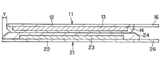
電池素子2は、図3に示すように、負極11と正極21とが積層されて構成される。負極11は、図4に示すように、負極集電体12上に、この負極集電体12の外周縁よりも後退した位置に外周縁がくるように負極合剤が塗布されてなる活物質層13と、この活物質層13の外周端面を覆うようにゲルポリマーが塗布されてなる電解質層14とが形成されている。また、負極11には、後述する負極端子リード4が取り付けられるリード取付部16が設けられる。
【0012】
このように、負極11においては、活物質層13の外周縁が負極集電体12の外周縁よりも後退した位置にくるように塗布されることで、活物質層13の周囲に亘って負極合剤が塗布されていない未塗布部15が設けられる。この未塗布部15は、後述する負極11の作製の際に負極集電体12の原反となるシート状の銅箔から所定形状に切り抜く際に、この銅箔上に塗布、形成された活物質層13からの活物質の脱落、剥離を防ぐことができ、内部ショート等の電池の故障を防止する。
【0013】
負極11においては、上述した未塗布部15の幅寸法xが0.1mm乃至2mmとなるように、好ましくは0.5mm乃至1mmとなるように負極合剤が塗布される。未塗布部15の幅が0.1mm未満であると上述した内部ショート等の原因となる活物質の脱落、剥離が有効に防止できず、また未塗布部15の幅が2mmよりも大きいと電池素子2のデッドスペースが大きくなり体積当たりの電池容量が低下する。なお、負極11は、未塗布部15がその幅寸法xが、上述した寸法の範囲内にあればその全周に亘って一様である必要はない。
【0014】
また、負極11は、活物質層12の外周端面を含む全体が電解質層13により覆われているため、一層活物質の脱落、剥離が防ぐことができ、内部ショート等の電池の故障を防止する。
【0015】
なお、正極12も、上述した負極11と同様の構成を有する。すなわち、正極21は、正極集電体22上に、この正極集電体22の外周縁よりも後退した位置に外周縁がくるように正極合剤が塗布されてなる活物質層23と、この活物質層23の外周端面を含む全体を覆うようにゲルポリマーが塗布されてなる電解質層24とが形成されている。また、正極12は、活物質層23の周囲に未塗布部25が設けられるとともに、後述する正極リード端子5が取り付けられるリード取付部26が設けられる。
【0016】
電池素子2においては、非水電解質電池の原理と安全性の観点から、通常、図3に示すように、負極11に比して正極21が小さく形成されている。しかしながら、塗布された活物質層の脆さという点では、負極11の活物質層13に比して正極21の活物質層23の方が弱い。また、正極21は、その集電体である金属箔に、通常アルミニウム箔が使用されており、シート状の原反から切り抜く際に切断面に生じるバリ22aが、図5に示すように負極11の集電体である銅箔の切断面に生じるバリ12aに比して大きくなりやすい。このため、正極21の集電体に生じたバリが、電解質層14,24を突き破り、正極21よりも外側に位置する負極集電体12に接触して内部ショートが発生することがある。
【0017】
上述した理由から、図6及び図7に示すように、正極21を構成する正極集電体22を負極11の形状に比して大きく、具体的にはその全周に亘って正極21の縁部が負極11の縁部よりもはみ出るように形成してもよい。このように、正極集電体22を負極11より大きく形成することで、正極集電体22のバリが負極集電体12に触れ難くなり、さらに活物質の脱落、剥離を防ぐための電解質層24の量も増やすことができるため、内部ショート等の電池の故障防止の効果も向上し、安全性の高いリチウムイオン二次電池1を作製することができる。
【0018】
このとき、正極21は、負極11との差分寸法yが0.1mm乃至0.5mmとなるように形成することが望ましい。リチウムイオン二次電池1においては、正極21が負極11からはみ出る量が0.1mm未満であると内部ショートを有効に防止することができず、また0.5mmよりも大きくはみ出るようにすると単位体積当たりの電池容量が低下する。なお、正極21は、負極11からはみ出る負極11との差分寸法yが、上述した寸法の範囲内にあればその全周に亘って一様である必要はない。
【0019】
電池素子2は、該電池素子2を構成する負極と電気的に接続される負極端子リード4及び正極と電気的に接続される正極端子リード5が設けられている。これら負極端子リード4及び正極端子リード5は、外装材3の外方へと引き出され、リチウムイオン二次電池1を駆動電源とするポータブル電子機器等の機器本体と電気的に接続される。
【0020】
負極端子リード4及び正極端子リード5は、詳しい図示を省略する負極及び正極を構成するそれぞれの集電体に接合されており、その材質としては、負極端子リードは銅、ニッケル、又はこれらの合金を用いることができる。また、正極端子リードには、高電位で溶解しないもの、例えばアルミニウム、チタン、或いはこれらの合金等が挙げられる。
【0021】
電池素子2には、固体電解質として、溶媒を一切含まない固体電解質を用いることができる。
【0022】
溶媒を含まない固体電解質としては、イオン伝導性高分子を用いた高分子固体電解質、さらにはイオン伝導性セラミクス、或いはイオン伝導性ガラスを用いた無機固体電解質等を用いることができる。
【0023】
例えば高分子固体電解質を形成するには、ポリエチレンオキサイドに代表されるようなエーテル結合を有する高分子マトリクス中に電解質を相溶させた高分子複合体を使用することができる。このとき、電解質としては、やはり通常の電池電解液に用いられる電解質を使用することができ、LiPF6、LiBF4、LiAsF6、LiClO4、LiCF3SO3、LiN(SO2CF3)2、LiC(SO2CF3)3、LiAlCl4、LiSiF6等のリチウム塩を使用することができる。
【0024】
高分子マトリクスとしては、上述したポリエチレンオキシドのような直鎖状の高分子だけでなく、側鎖構造を有したくし型高分子、あるいは主鎖にシロキサン構造、ポリフォスファゼン構造等の無機高分子構造を有したもの等も使用することができるが、勿論、これらに限られるものではない。
【0025】
あるいは、通常のゲル状電解質電池とすることも可能である。例えばゲル状電解質電池を考えた場合、ゲル状電解質に用いられる高分子材料としては、シリコンゲル、アクリルゲル、アクリロニトリルゲル、ポリフォスファゼン変成ポリマー、ポリエチレンオキサイド、ポリプロピレンオキサイド、及びこれらの複合ポリマーや架橋ポリマー、変成ポリマー等、もしくはフッ素系ポリマーとして、例えばポリ(ビニリデンフルオロライド)やポリ(ビニリデンフルオロライド-co-ヘキサフルオロプロピレン)、ポリ(ビニリデンフルオロライド-co-テトラフルオロエチレン)、ポリ(ビニリデンフルオロライド-co-トリフルオロエチレン)等及びこれらの混合物が各種使用できるが、勿論これらに限定されるものではない。
【0026】
正極活物質層または負極活物質層に積層されている固体電解質、またはゲル状電解質は、高分子化合物と電解質塩と溶媒、(ゲル電解質の場合は、さらに可塑剤)からなる溶液を正極活物質層または負極活物質層に含浸させ、溶媒を除去し固体化したものである。正極活物質層または負極活物質層に積層された固体電解質、またはゲル状電解質は、その一部が正極活物質層または負極活物質層に含浸されて固体化されている。架橋系の場合は、その後、光または熱で架橋して固体化される。
【0027】
ゲル状電解質は、リチウム塩を含む可塑剤と2重量%以上〜30重量%以下のマトリクス高分子からなる。このとき、エステル類、エーテル類、炭酸エステル類などを単独または可塑剤の一成分として用いることができる。
【0028】
ゲル状電解質を調整するにあたり、このような炭酸エステル類をゲル化するマトリクス高分子としては、ゲル状電解質を構成するのに使用されている種々の高分子が利用できるが、酸化還元安定性から、たとえばポリ(ビニリデンフルオロライド)やポリ(ビニリデンフルオロライド-co-ヘキサフルオロプロピレン)などのフッ素系高分子を用いることが望ましい。
【0029】
高分子固体電解質は、リチウム塩とそれを溶解する高分子化合物からなり、高分子化合物としては、ポリ(エチレンオキサイド)や同架橋体などのエーテル系高分子、ポリ(メタクリレート)エステル系、アクリレート系、ポリ(ビニリデンフルオロライド)やポリ(ビニリデンフルオロライド-co-ヘキサフルオロプロピレン)などのフッ素系高分子などを単独、または混合して用いることができるが、酸化還元安定性から、たとえばポリ(ビニリデンフルオロライド)やポリ(ビニリデンフルオロライド-co-ヘキサフルオロプロピレン)などのフッ素系高分子を用いることが望ましい。
【0030】
このようなゲル状電解質または高分子固体電解質に含有させるリチウム塩として通常の電池電解液に用いられるリチウム塩を使用することができ、リチウム化合物(塩)としては、例えば以下のものが挙げられるが、これらに限定されるものではない。
【0031】
例えば、塩化リチウム、臭化リチウム、ヨウ化リチウム、塩素酸リチウム、過塩素酸リチウム、臭素酸リチウム、ヨウ素酸リチウム、硝酸リチウム、テトラフルオロほう酸リチウム、ヘキサフルオロリン酸リチウム、酢酸リチウム、ビス(トリフルオロメタンスルフォニル)イミドリチウム、LiAsF6、LiCF3SO3、LiC(SO2CF3)3、LiAlCl4、LiSiF6等を挙げることができる。
【0032】
これらリチウム化合物は単独で用いても複数を混合して用いても良いが、これらの中でLiPF6、LiBF4が酸化安定性の点から望ましい。
【0033】
リチウム塩を溶解する濃度として、ゲル状電解質なら、可塑剤中に0.1〜3.0モルで実施できるが、好ましくは0.5から2.0モル/リットルで用いることができる。
【0034】
リチウムイオン二次電池1の負極としては、リチウムをドープ、脱ドープできる材料を負極活物質として使用することができる。このような負極の構成材料としては、例えば難黒鉛化炭素系材料や黒鉛系材料の炭素材料を使用することができる。より具体的には、熱分解炭素類、コークス類(ピッチコークス、ニードルコークス、石油コークス)、黒鉛類、ガラス状炭素類、有機高分子化合物焼成体(フェノール樹脂、フラン樹脂等を適当な温度で焼成し炭素化したもの)、炭素繊維、活性炭等の炭素材料を使用することができる。この他、リチウムをドープ、脱ドープできる材料としては、ポリアセチレン、ポリピロール等の高分子やSnO2 等の酸化物を使用することもできる。このような負極活物質を使用して負極を形成するに際しては、公知の結着剤等を添加することができる。
【0035】
また、リチウムイオン二次電池1の負極には、上述した材料が調製された負極合剤が塗布される電極集電体として金属箔、例えば銅箔等が使用される。
【0036】
正極は、目的とする電池の種類に応じて、金属酸化物、金属硫化物または特定の高分子を正極活物質として用いて構成することができる。例えばリチウムイオン電池を構成する場合、正極活物質としては、TiS2、MoS2、NbSe2,V2O5等のリチウムを含有しない金属硫化物あるいは酸化物や、LiMO2 (式中Mは一種以上の遷移金属を表し、xは電池の充放電状態によって異なり、通常0.05以上1.10以下である。)を主体とするリチウム複合酸化物等を使用することができる。このリチウム複合酸化物を構成する遷移金属Mとしては、Co,Ni,Mn等が好ましい。このようなリチウム複合酸化物の具体例としてはLiCoO2,LiNiO2,LiNiyCo1-yO2(式中、0<y<1である。)、LiMn2O4等を挙げることができる。これらリチウム複合酸化物は、高電圧を発生でき、エネルギー密度的に優れた正極活物質となる。正極には、これらの正極活物質の複数種を併せて使用してもよい。また、以上のような正極活物質を使用して正極を形成するに際して、公知の導電剤や結着剤等を添加することができる。
【0037】
また、リチウムイオン二次電池1の正極には、上述した材料が調製された正極合剤が塗布される電極集電体として金属箔、例えばアルミニウム箔等が使用される。
【0038】
なお、リチウムイオン二次電池1は、電池素子2の構造として、上述した積み重ね型の他、正極及び負極を固体電解質を挟んで重ね合わせ、これを巻き取った巻き取り型、正極及び負極を固体電解質を挟んで重ね合わせ、これを交互に折り畳んだ折り畳み型等を挙げることができ、任意に選択することができる。
【0039】
外装材3は、例えば外装保護層、アルミニウム層及び熱溶着層(ラミネート最内層)の3層からなるヒートシールタイプのシート状ラミネートフィルムを使用する。熱溶着層は、電池素子を封入する際の熱溶着による封入を目的としたもので、プラスチックフィルムが使用されている。プラスチックフィルムには、ポリエチレン、ポリプロピレン、ポリエチレンテフタレート等が用いられるが、熱可塑性のプラスチック材料であればその原料を問わない。
【0040】
本発明は、一次電池、二次電池のいずれにも適用可能であるが、特に上述したリチウムイオン二次電池1や、リチウム金属を負極材料として使用するリチウム二次電池等の如き非水電解質二次電池へ適用することで、大きな効果を得ることができる。
【0041】
上述したリチウムイオン二次電池1の製造方法について、以下に説明する。
【0042】
まず、リチウムイオン二次電池1においては、電池素子2を構成する負極及び正極が製造される。
【0043】
負極は、図8に示すように、負極集電体12となる銅箔の原反シート12A上にスラリー状に調製された負極合剤が塗布されて活物質層13が形成される活物質塗布工程が行われる。活物質層13は、例えばダイコータ等の塗布装置を用いて負極集電体12の原反シート12A上に、負極合剤が所定間隔ごとに間欠塗布され、その後塗布された負極合剤を乾燥させ、ロールプレス機等で圧縮して成形される。
【0044】
次に、上述した活物質塗布工程にて活物質層13が形成された原反シート12Aから所定の電極形状に負極集電体12を切り抜く切抜き工程が行われる。切抜き工程においては、図8に示す点線に沿って、すなわち負極集電体12が未塗布部15を有するように負極集電体12の外周縁よりも活物質層13の外周縁が後退した位置にくるように切り抜かれる。切抜き工程では、所定の電極形状に対応する金型を使用した押し切りや、レーザカット等の方法で、原反シート12Aから負極集電体12が切り抜かれる。
【0045】
そして、切り抜き工程において図9に示す形状に切り抜かれた負極集電体12と、この負極集電体12に形成された活物質層13上に、ゲルポリマーを塗布して電解質層13を形成するポリマー塗布工程が行われる。ポリマー塗布工程では、負極集電体12上に形成された活物質層12の外周端面を含む全体を覆うようにゲルポリマーが塗布され、図4に示すように活物質層13全体を覆う電解質層が形成される。
【0046】
また、正極は、詳しい図示を省略するが上述した負極11と同様の工程を経て製造される。すなわち、正極集電体となるアルミニウム箔の原反シート上に活物質層を形成する活物質塗布工程と、活物質層が形成されたアルミニウム箔の原反シートを所定の電極形状に切り抜く切抜き工程とが行われ、その後解質層を形成するポリマー塗布工程が行われて正極が作製される。
【0047】
なお、上述した負極11と正極21の作製に際しては、所定の電極形状に切り抜き後に、電解質層を形成したが、ゲルポリマーを塗布して電解質層を形成後に所定の電極形状への切り抜きを行ってもよい。
【0048】
リチウムイオン二次電池1においては、上述したように作製された負極及び正極を、それぞれの活物質層12同士が対向するように積層して電池素子2とされる。リチウムイオン二次電池1は、負極と正極とを積層してなる電池素子2を外装材3内に収納し、この外装材3の周囲部を熱溶着して内部の電池素子3を密封することにより完成する。
【0049】
【実施例】
次に、本発明の具体的な実施例及び比較例について、実験結果に基づき説明する。
【0050】
まず、以下に示すように実施例のサンプル電池及び比較例のサンプル電池を作製した。
【0051】
実施例1
まず、負極を以下のようにして作製した。
【0052】
粉砕した黒鉛粉末を90重量部と、結着剤としてポリ(ビニリデンフルオロライド-co-ヘキサフルオロプロピレン)10重量部とを混合して負極合剤を調製し、さらにこれをN−メチル−2−ピロリドンに分散させてスラリー状とした。
【0053】
そして、このスラリー状の負極合剤を負極集電体である厚さ10μmの帯状銅箔の片面に均一に、未塗布部が1mmとなるように塗布し、乾燥させてロールプレス機で圧縮成形し、所定形状に切り抜いて負極を作製した。
【0054】
一方、正極を以下のようにして作製した。
【0055】
正極活物質として使用するLiCoO2を得るため、炭酸リチウムと炭酸コバルトを0.5モル対1モルの比率で混合し、空気中の900℃条件下で5時間焼成した。
【0056】
上述した方法で得られたLiCoO2を91重量部、導電剤として黒鉛6重量部、結着剤としてポリ(ビニリデンフルオロライド-co-ヘキサフルオロプロピレン)10重量部とを混合して正極合剤を調製し、さらにこれをN−メチル−2−ピロリドンに分散させスラリー状とした。
【0057】
そして、このスラリー状の正極合剤を正極集電体である厚さ20μmの帯状アルミニウム箔の片面に均一に塗布し、乾燥させてロールプレス機で圧縮成形し、所定形状に切り抜いて正極を作製した。
【0058】
このとき、正極は、負極に比して大きく、具体的には図6に示す電池素子3の如く正極の縁部と負極の縁部との差分寸法yが0.5mmとなるように作製した。
【0059】
さらに、ゲル状電解質(電解質層)を以下のようにして得た。
【0060】
活物質層が形成されかつ所定形状にレーザカットされた負極、正極上に、炭酸エチレン(EC)42.5重量部、炭酸プロピレン(PC)42.5重量部及びLiPF615重量部からなる可塑剤30重量部に、重量平均分子量Mw60万のポリ(ビニリデンフルオロライド-co-ヘキサフルオロプロピレン)を10重量部、そして炭酸ジエチルを60重量部混合溶解させた溶液を均一に塗布し、含浸させ、常温で8時間放置し、炭酸ジメチルを気化、除去した。
【0061】
そして、上述して作製した負極及び正極に対してアルミニウムからなる正極端子リード、及びニッケルからなる負極端子リードをそれぞれ溶接した後、負極と正極とをそれぞれの活物質層が電解質層を介して対向するように積層して電池素子3を作製した。この電池素子をラミネートフィルムからなる外装材内に収納し、その外周部分を200℃の温度条件下で10秒間、シール機によりシール幅5mmで熱融着して、サンプル電池を作製した。
【0062】
実施例2
正極を負極に比して小さく、具体的には図3に示す如く、負極の端部が正極の端部よりも内側に来る形状に電極を作製し、負極と同様正極の未塗布部も1mmとする以外、上述した実施例と同様に作製した。
【0063】
比較例1
負極及び正極は、実施例1と同様の組成のものを使用し、その他は以下のようにして作製した。
【0064】
まず、図10に示すように、負極31と正極32、及びこれら負極31と正極32との間に介在させる多孔質膜(架橋ポリマーシート)33を積層させた状態で、所定の電極形状に裁断する。そして、多孔質膜33に電解質溶液を含浸させて膨張させ、負極31と正極32の活物質層31a,32aの切断面が膨張してはみ出した電解質で覆われるにして電池素子30を作製した。なお、この比較例1のサンプル電池においては、活物質層31a,32aの切断面を覆う電解質の厚さは0.5mmである。
【0065】
上述したように作製された電池素子30を実施例1と同様にラミネートフィルムからなる外装材内に収納し、その外周部分を200℃の温度条件下で10秒間、シール機によりシール幅5mmで熱融着して、サンプル電池を作製した。
【0066】
比較例2
負極、正極及びゲル状電解質(電解質層)は、実施例1と同様の組成のものを使用し、その他は以下のようにして作製した。
【0067】
まず、電極集電体となる金属箔原反上に活物質層と電解質層とを形成した後に所定の電極形状に裁断した負極41と正極42とを、図11に示すように、それぞれの電解質層41a,42aを挟んで互いの活物質層41b,42bが対向するように積層し、電池素子40を作製した。
【0068】
上述したように作製された電池素子40を実施例1と同様にラミネートフィルムからなる外装材内に収納し、その外周部分を200℃の温度条件下で10秒間、シール機によりシール幅5mmで熱融着して、サンプル電池を作製した。
【0069】
上述したような構成のサンプル電池を各実施例、比較例についてそれぞれ50個ずつ作製し、充放電を行って内部ショートの発生の有無を調べた。この結果を表1に示す。
【0070】
【表1】

表1に示すように、各比較例の方が、各実施例に比べて、内部ショートを起こしたサンプル電池を多く確認することができた。
【0072】
比較例1においては、活物質層31a,32aの切断面を電解質で覆ってはいるものの、電池素子30の作成段階で切断面を被覆する電解質が設けられる前に活物質層31a,32aが裁断されるため、この裁断時に脱落した活物質により内部ショートが発生している。
【0073】
また、比較例2においては、活物質層41b,42bの切断面が露出しているため、比較例1よりも活物質の脱落しやすく、内部ショートも多数発生している。
【0074】
これに対し、実施例1及び実施例2においては、活物質層を電極集電体に比して小さく形成することで活物質層を裁断せずに電池素子を作製するとともに、活物質層が電解質層により覆われている。このため、活物質層からの活物質の脱落が無く、この活物質の脱落による内部ショートが防止されている。なお、実施例2において1個のサンプル電池に内部ショートが発生しているのは、原反シートからの切り抜きの際に生じた負極集電体のバリが正極集電体に接触したためである。
【0075】
以上から、実施例1及び実施例2のように活物質層を電極集電体に比して小さく形成することで電池電極作製の際に活物質層を裁断しないようにすること、及び活物質層全体を電解質層で覆うようにすることで、活物質層の脱落による電池の内部ショートの発生を有効に防止し得ると判断できる。
【0076】
また、負極と正極との集電体同士が接触して生じる内部ショートの発生を防止するには、実施例1の如く正極を負極に比して大きく形成し、正極の縁部を負極の全周に亘ってはみ出すようにして電池素子を形成することが望ましい。
【0077】
【発明の効果】
以上、詳細に説明したように本発明に係る非水電解質電池は、電解質層の外周縁を電極集電体の外周縁よりも後退した位置にくるように形成することで、電極集電体を所定の形状に切り抜く際に、活物質層を切断せずに負極及び正極を作製することができる。また、本発明に係る非水電解質電池では、負極活物質層及び正極活物質層の周囲において、負極集電体上の負極合剤及び正極集電体の正極合剤が塗布されていない未塗布部を設け、この未塗布部の幅が0.1mm乃至2mmとなるようにする。また、本発明に係る非水電解質電池は、電極集電体の一端は、電極リード端子が取り付けられるリード取付部が設けられ、電極集電体上に形成された活物質層の外周端面を含む全体及びリード取付部を除く未塗布部が電解質層によって被覆される。このような本発明に係る非水電解質電池によれば、活物質層からの活物質の脱落を有効に防ぐことができ、内部ショートの発生による電池の故障を防止して、電池の品質、安全性を向上させることができる。
【図面の簡単な説明】
【図1】リチウムイオン二次電池の斜視図である。
【図2】リチウムイオン二次電池の図1中A−A線で切断した状態を示す縦断面図である。
【図3】負極と正極とが積層された電池素子の縦断面図である。
【図4】負極の斜視図である。
【図5】電池素子の要部拡大縦断面図である。
【図6】他の電池素子の縦断面図である。
【図7】他の電池素子の要部拡大縦断面図である。
【図8】リチウムイオン二次電池の製造工程を説明する図であり、銅箔のシート状原反に活物質層を形成した状態を示す要部斜視図である。
【図9】リチウムイオン二次電池の製造工程を説明する図であり、シート状原反から切り抜いた状態を示す斜視図である。
【図10】比較例1に使用した電池素子の要部拡大縦断面図である。
【図11】比較例2に使用した電池素子の縦断面図である。
【符号の説明】
1 リチウムイオン二次電池,2 電池素子,3 外装材,4 負極端子リード,5 正極端子リード,11 負極,12 負極集電体,13 活物質層,14 電解質層,15 未塗布部[0001]
BACKGROUND OF THE INVENTION
The present invention relates to a non-aqueous electrolyte battery in which a battery element is housed in a packaging material made of a laminate film, and more particularly to an improvement in the structure of a battery element electrode in a gel electrolyte battery, a solid electrolyte battery, or the like.
[0002]
[Prior art]
In recent years, many portable electronic devices such as camera-integrated video tape recorders, portable telephones, portable personal computers, and the like have appeared, and their size and weight have been reduced. As a driving power source for these portable electronic devices, batteries, particularly secondary batteries, and particularly non-aqueous electrolyte secondary batteries (so-called lithium ion secondary batteries), are lightweight, thin, and highly flexible in shape. Research and development is actively underway.
[0003]
As electrolytes used in batteries as described above, solid electrolytes are actively researched, especially gel electrolytes that are solid electrolytes containing plasticizers, and high electrolytes in which lithium salts are dissolved in polymers. Molecular solid electrolytes are attracting attention. In a battery using such a solid electrolyte, there is no risk of leakage of the electrolyte. Therefore, a plastic film or a so-called laminate film in which plastic and metal are laminated is used as an exterior material, and a battery element is provided in the laminate film. By encapsulating, it is possible to achieve a reduction in thickness, weight, and improvement in the degree of freedom of shape.
[0004]
[Problems to be solved by the invention]
In a non-aqueous electrolyte battery such as a non-aqueous electrolyte secondary battery, the space in the portable electronic device can be effectively utilized by taking advantage of the above-described advantages of being thin and light and having a high degree of freedom in shape. There are various spaces that can be formed in such portable devices, and accordingly, non-aqueous electrolyte batteries are required to cope with various shapes, and the shapes of electrodes constituting the battery elements are also complicated.
[0005]
In a conventional non-aqueous electrolyte battery, an active material layer and an electrolyte layer are coated on a raw material of a metal foil serving as an electrode current collector, and then cut into a predetermined shape by punching using a mold or the like. The negative electrode and positive electrode which comprise a battery element are produced. In the negative electrode and the positive electrode thus manufactured, the active material layer and the electrolyte layer formed on the electrode current collector are cut together with the electrode current collector, so that the cut surface of the active material layer is exposed. In the conventional non-aqueous electrolyte battery, the active material is dropped from the cut surface of the active material layer, causing a failure of the battery such as an internal short circuit, and reducing the quality of the battery itself.
[0006]
Accordingly, an object of the present invention is to provide a non-aqueous electrolyte battery that is improved in quality and safety by preventing the active material from falling off from the battery electrode constituting the battery element.
[0007]
[Means for Solving the Problems]
The nonaqueous electrolyte battery according to the present invention having the above-described object includes an electrode current collector, an active material layer formed by applying an electrode material on the electrode current collector, and a matrix polymer on the active material layer. A battery element having a negative electrode and a positive electrode having a gel electrolyte made of a polymer composite in which an electrolyte is mixed therein or an electrolyte layer formed of a solid electrolyte,In each of the negative electrode and the positive electrode,The outer peripheral edge of the active material layer is recessed from the outer peripheral edge of the electrode current collector.,Active material layerSurroundingsIn negative electrode mixtureOr cathode mixIs provided with an uncoated portion where no coating is applied, and the width of the uncoated portion is 0.1 mm to 2 mm,One end of the electrode current collector has a lead attachment part to which an electrode lead terminal is attached,Active material layer outer peripheral end faceIncluding the whole and unapplied parts excluding lead mounting partsCovered by an electrolyte layer.
[0008]
The non-aqueous electrolyte battery according to the present invention having the above-described configuration is formed by cutting the electrode current collector into a predetermined shape by forming the outer peripheral edge of the electrolyte layer so as to recede from the outer peripheral edge of the electrode current collector. The negative electrode and the positive electrode are produced without cutting the active material layer. In the nonaqueous electrolyte battery according to the present invention, the negative electrode active material layerAnd positive electrode active material layerofSurroundingsOn the negative electrode current collectorofNegative electrode mixtureAnd positive electrode mixture of positive electrode current collectorAn uncoated portion where no coating is applied is provided, and the width of the uncoated portion is set to 0.1 mm to 2 mm. Moreover, the non-aqueous electrolyte battery according to the present invention isOne end of the electrode current collector is provided with a lead attachment part to which an electrode lead terminal is attached,The outer peripheral end surface of the active material layer formed on the electrode current collectorIncluding the whole and unapplied parts excluding lead mounting partsCovered by an electrolyte layer. According to such a non-aqueous electrolyte battery according to the present invention, it is possible to effectively prevent the active material from falling off the active material layer, to prevent battery failure due to the occurrence of an internal short circuit, and to improve battery quality and safety. Improve sexiness.
[0009]
DETAILED DESCRIPTION OF THE INVENTION
Hereinafter, specific embodiments of the nonaqueous electrolyte battery according to the present invention will be described in detail with reference to the drawings. The lithium ion secondary battery according to the present invention is, for example, a solid electrolyte battery or a gel electrolyte battery.
[0010]
Specifically, as shown in FIGS. 1 and 2, the lithium ion secondary battery 1 is a battery in which a solid electrolyte or a gel electrolyte is disposed between a positive electrode active material layer and a negative electrode active material layer. An
[0011]
As shown in FIG. 3, the
[0012]
As described above, in the
[0013]
In the
[0014]
Moreover, since the whole
[0015]
The
[0016]
In the
[0017]
For the reasons described above, as shown in FIGS. 6 and 7, the positive electrode
[0018]
At this time, the
[0019]
The
[0020]
The negative electrode terminal lead 4 and the positive
[0021]
In the
[0022]
As a solid electrolyte not containing a solvent, a polymer solid electrolyte using an ion conductive polymer, an ion conductive ceramic, an inorganic solid electrolyte using ion conductive glass, or the like can be used.
[0023]
For example, in order to form a polymer solid electrolyte, a polymer composite in which an electrolyte is compatible in a polymer matrix having an ether bond represented by polyethylene oxide can be used. At this time, as an electrolyte, an electrolyte used for a normal battery electrolyte can be used, and LiPF6, LiBFFour, LiAsF6LiClOFour, LiCFThreeSOThree, LiN (SO2CFThree)2, LiC (SO2CFThree)ThreeLiAlClFour, LiSiF6Lithium salts such as can be used.
[0024]
The polymer matrix is not only a linear polymer such as polyethylene oxide, but also a comb polymer having a side chain structure, or an inorganic polymer such as a siloxane structure or polyphosphazene structure in the main chain. Those having a structure can also be used, but the present invention is not limited to these.
[0025]
Or it is also possible to set it as a normal gel electrolyte battery. For example, in the case of a gel electrolyte battery, polymer materials used for the gel electrolyte include silicon gel, acrylic gel, acrylonitrile gel, polyphosphazene modified polymer, polyethylene oxide, polypropylene oxide, and composite polymers and crosslinks thereof. Polymers, modified polymers, etc., or fluoropolymers such as poly (vinylidene fluoride), poly (vinylidene fluoride-co-hexafluoropropylene), poly (vinylidene fluoride-co-tetrafluoroethylene), poly (vinylidene fluoro) Ride-co-trifluoroethylene) and mixtures thereof and various mixtures thereof can be used, but of course not limited thereto.
[0026]
For the solid electrolyte or gel electrolyte laminated on the positive electrode active material layer or the negative electrode active material layer, a solution comprising a polymer compound, an electrolyte salt, and a solvent (or a plasticizer in the case of a gel electrolyte) is used as the positive electrode active material. A layer or a negative electrode active material layer is impregnated, and the solvent is removed and solidified. Part of the solid electrolyte or the gel electrolyte laminated on the positive electrode active material layer or the negative electrode active material layer is impregnated into the positive electrode active material layer or the negative electrode active material layer to be solidified. In the case of a crosslinked system, it is then solidified by crosslinking with light or heat.
[0027]
The gel electrolyte is composed of a plasticizer containing a lithium salt and a matrix polymer of 2 wt% to 30 wt%. At this time, esters, ethers, carbonates and the like can be used alone or as one component of a plasticizer.
[0028]
In preparing the gel electrolyte, various polymers used to form the gel electrolyte can be used as the matrix polymer for gelling such carbonates. From the viewpoint of redox stability, For example, it is desirable to use a fluorine-based polymer such as poly (vinylidene fluoride) or poly (vinylidene fluoride-co-hexafluoropropylene).
[0029]
The polymer solid electrolyte is composed of a lithium salt and a polymer compound that dissolves the lithium salt. Examples of the polymer compound include ether polymers such as poly (ethylene oxide) and cross-linked polymers, poly (methacrylate) esters, and acrylates. Fluorine polymers such as poly (vinylidene fluoride) and poly (vinylidene fluoride-co-hexafluoropropylene) can be used singly or in combination. For example, poly (vinylidene) can be used because of redox stability. Fluoropolymers such as (fluoride) and poly (vinylidene fluoride-co-hexafluoropropylene) are preferably used.
[0030]
As a lithium salt to be contained in such a gel electrolyte or a polymer solid electrolyte, a lithium salt used in a normal battery electrolyte can be used. Examples of the lithium compound (salt) include the following. However, it is not limited to these.
[0031]
For example, lithium chloride, lithium bromide, lithium iodide, lithium chlorate, lithium perchlorate, lithium bromate, lithium iodate, lithium nitrate, lithium tetrafluoroborate, lithium hexafluorophosphate, lithium acetate, bis (trifluoro) Lomethanesulfonyl) imidolithium, LiAsF6, LiCFThreeSOThree, LiC (SO2CFThree)ThreeLiAlClFour, LiSiF6Etc.
[0032]
These lithium compounds may be used alone or in combination, and among them, LiPF6, LiBFFourIs desirable from the viewpoint of oxidation stability.
[0033]
As a concentration for dissolving the lithium salt, a gel electrolyte can be used at 0.1 to 3.0 mol in the plasticizer, but preferably 0.5 to 2.0 mol / liter.
[0034]
As the negative electrode of the lithium ion secondary battery 1, a material capable of doping and dedoping lithium can be used as the negative electrode active material. As a constituent material of such a negative electrode, for example, a non-graphitizable carbon material or a carbon material such as a graphite material can be used. More specifically, pyrolytic carbons, cokes (pitch coke, needle coke, petroleum coke), graphites, glassy carbons, organic polymer compound fired bodies (phenolic resin, furan resin, etc.) at an appropriate temperature. Carbon materials such as those obtained by firing and carbonization), carbon fibers, activated carbon, and the like can be used. Other materials that can be doped and dedoped with lithium include polymers such as polyacetylene and polypyrrole, and SnO.2Oxides such as these can also be used. In forming a negative electrode using such a negative electrode active material, a known binder or the like can be added.
[0035]
In addition, a metal foil, such as a copper foil, is used for the negative electrode of the lithium ion secondary battery 1 as an electrode current collector to which the negative electrode mixture prepared from the above-described material is applied.
[0036]
The positive electrode can be configured using a metal oxide, a metal sulfide, or a specific polymer as the positive electrode active material, depending on the type of the target battery. For example, when constituting a lithium ion battery, the positive electrode active material is TiS.2, MoS2, NbSe2, V2OFiveLithium-free metal sulfides or oxides such as LiMO2(Wherein M represents one or more transition metals, and x varies depending on the charge / discharge state of the battery, and is usually 0.05 or more and 1.10 or less), etc. it can. As the transition metal M constituting this lithium composite oxide, Co, Ni, Mn and the like are preferable. A specific example of such a lithium composite oxide is LiCoO.2, LiNiO2, LiNiyCo1-yO2(Where 0 <y <1), LiMn2OFourEtc. These lithium composite oxides can generate a high voltage and become a positive electrode active material excellent in energy density. A plurality of these positive electrode active materials may be used in combination for the positive electrode. Moreover, when forming a positive electrode using the above positive electrode active material, a well-known electrically conductive agent, a binder, etc. can be added.
[0037]
In addition, a metal foil, such as an aluminum foil, is used for the positive electrode of the lithium ion secondary battery 1 as an electrode current collector to which the positive electrode mixture prepared with the above-described material is applied.
[0038]
In addition, the lithium ion secondary battery 1 has a
[0039]
For the
[0040]
The present invention can be applied to both a primary battery and a secondary battery. In particular, the
[0041]
The manufacturing method of the lithium ion secondary battery 1 mentioned above is demonstrated below.
[0042]
First, in the lithium ion secondary battery 1, the negative electrode and positive electrode which comprise the
[0043]
As shown in FIG. 8, the negative electrode is applied with an active material layer in which an
[0044]
Next, a cutting process is performed in which the negative electrode
[0045]
Then, a gel polymer is applied on the negative electrode
[0046]
Moreover, although a detailed illustration is omitted, the positive electrode is manufactured through the same process as the
[0047]
In preparing the
[0048]
In the lithium ion secondary battery 1, the negative electrode and the positive electrode manufactured as described above are stacked so that the active material layers 12 face each other to form the
[0049]
【Example】
Next, specific examples and comparative examples of the present invention will be described based on experimental results.
[0050]
First, as shown below, a sample battery of an example and a sample battery of a comparative example were manufactured.
[0051]
Example 1
First, a negative electrode was produced as follows.
[0052]
90 parts by weight of the pulverized graphite powder and 10 parts by weight of poly (vinylidene fluoride-co-hexafluoropropylene) as a binder were mixed to prepare a negative electrode mixture, and this was further mixed with N-methyl-2- Dispersed in pyrrolidone to form a slurry.
[0053]
Then, this slurry-like negative electrode mixture is uniformly applied to one side of a 10 μm-thick strip-shaped copper foil, which is a negative electrode current collector, so that the uncoated portion becomes 1 mm, dried, and compression-molded with a roll press. And it cut out to the predetermined shape and produced the negative electrode.
[0054]
On the other hand, the positive electrode was produced as follows.
[0055]
LiCoO used as positive electrode active material2In order to obtain the above, lithium carbonate and cobalt carbonate were mixed at a ratio of 0.5 mol to 1 mol, and calcined in air at 900 ° C. for 5 hours.
[0056]
LiCoO obtained by the method described above2Was mixed with 91 parts by weight of graphite, 6 parts by weight of graphite as a conductive agent, and 10 parts by weight of poly (vinylidene fluoride-co-hexafluoropropylene) as a binder, to prepare a positive electrode mixture, which was further mixed with N-methyl. Dispersed in -2-pyrrolidone to form a slurry.
[0057]
And this slurry-like positive electrode mixture is uniformly applied to one side of a 20 μm-thick strip-shaped aluminum foil as a positive electrode current collector, dried, compression-molded with a roll press, and cut into a predetermined shape to produce a positive electrode did.
[0058]
At this time, the positive electrode was larger than the negative electrode, and specifically, the battery was manufactured such that the difference dimension y between the edge of the positive electrode and the edge of the negative electrode was 0.5 mm as in the
[0059]
Furthermore, a gel electrolyte (electrolyte layer) was obtained as follows.
[0060]
42.5 parts by weight of ethylene carbonate (EC), 42.5 parts by weight of propylene carbonate (PC) and LiPF are formed on the negative electrode and the positive electrode on which the active material layer is formed and laser-cut into a predetermined shape.6A uniform solution of 10 parts by weight of poly (vinylidene fluoride-co-hexafluoropropylene) having a weight average molecular weight Mw of 600,000 and 60 parts by weight of diethyl carbonate in 30 parts by weight of a plasticizer consisting of 15 parts by weight It was applied, impregnated, and allowed to stand at room temperature for 8 hours to vaporize and remove dimethyl carbonate.
[0061]
And after welding the positive electrode terminal lead which consists of aluminum, and the negative electrode terminal lead which consists of nickel with respect to the negative electrode and positive electrode which were produced above, each negative electrode and a positive electrode face each other through an electrolyte layer Thus, the
[0062]
Example 2
The positive electrode is made smaller than the negative electrode, specifically, as shown in FIG. 3, the electrode is prepared in such a shape that the end of the negative electrode is inward of the end of the positive electrode. Other than the above, it was fabricated in the same manner as in the above-described example.
[0063]
Comparative Example 1
A negative electrode and a positive electrode having the same composition as in Example 1 were used, and the others were produced as follows.
[0064]
First, as shown in FIG. 10, a
[0065]
The
[0066]
Comparative Example 2
The negative electrode, the positive electrode, and the gel electrolyte (electrolyte layer) having the same composition as in Example 1 were used, and the others were produced as follows.
[0067]
First, as shown in FIG. 11, the
[0068]
The
[0069]
Fifty sample batteries having the above-described configuration were prepared for each of the examples and comparative examples, and charging / discharging was performed to examine whether or not an internal short circuit occurred. The results are shown in Table 1.
[0070]
[Table 1]
As shown in Table 1, in each comparative example, it was possible to confirm more sample batteries that caused an internal short circuit than in each example.
[0072]
In Comparative Example 1, although the cut surfaces of the
[0073]
Further, in Comparative Example 2, since the cut surfaces of the active material layers 41b and 42b are exposed, the active material is more easily dropped than in Comparative Example 1, and many internal shorts are generated.
[0074]
On the other hand, in Example 1 and Example 2, while forming a battery element without cutting an active material layer by forming an active material layer smaller than an electrode current collector, an active material layer It is covered with an electrolyte layer. For this reason, there is no dropout of the active material from the active material layer, and an internal short circuit due to the dropout of the active material is prevented. In Example 2, the internal short circuit occurred in one sample battery because the burrs of the negative electrode current collector generated when the sample battery was cut out from the original fabric sheet contacted the positive electrode current collector.
[0075]
As described above, the active material layer is formed smaller than the electrode current collector as in Example 1 and Example 2, so that the active material layer is not cut when the battery electrode is manufactured, and the active material By covering the entire layer with the electrolyte layer, it can be determined that the occurrence of an internal short circuit of the battery due to the dropping of the active material layer can be effectively prevented.
[0076]
Further, in order to prevent the occurrence of an internal short circuit that occurs when the current collectors of the negative electrode and the positive electrode come into contact with each other, the positive electrode is formed larger than the negative electrode as in Example 1, and the edge of the positive electrode is formed on the entire negative electrode. It is desirable to form the battery element so as to protrude over the circumference.
[0077]
【The invention's effect】
As described above in detail, the nonaqueous electrolyte battery according to the present invention forms the electrode current collector by forming the outer peripheral edge of the electrolyte layer at a position that is recessed from the outer peripheral edge of the electrode current collector. When cutting into a predetermined shape, the negative electrode and the positive electrode can be produced without cutting the active material layer. In the nonaqueous electrolyte battery according to the present invention, the negative electrode active material layerAnd positive electrode active material layerofSurroundingsOn the negative electrode current collectorofNegative electrode mixtureAnd positive electrode mixture of positive electrode current collectorAn uncoated portion where no coating is applied is provided, and the width of the uncoated portion is set to 0.1 mm to 2 mm. Moreover, the non-aqueous electrolyte battery according to the present invention isOne end of the electrode current collector is provided with a lead attachment part to which an electrode lead terminal is attached,The outer peripheral end surface of the active material layer formed on the electrode current collectorIncluding the whole and unapplied parts excluding lead mounting partsCovered by an electrolyte layer. According to such a non-aqueous electrolyte battery according to the present invention, it is possible to effectively prevent the active material from falling off the active material layer, to prevent battery failure due to the occurrence of an internal short circuit, and to improve battery quality and safety. Can be improved.
[Brief description of the drawings]
FIG. 1 is a perspective view of a lithium ion secondary battery.
FIG. 2 is a longitudinal sectional view showing a state of the lithium ion secondary battery cut along line AA in FIG.
FIG. 3 is a longitudinal sectional view of a battery element in which a negative electrode and a positive electrode are stacked.
FIG. 4 is a perspective view of a negative electrode.
FIG. 5 is an enlarged vertical sectional view of a main part of the battery element.
FIG. 6 is a longitudinal sectional view of another battery element.
FIG. 7 is an enlarged vertical sectional view of a main part of another battery element.
FIG. 8 is a diagram for explaining a manufacturing process of a lithium ion secondary battery, and is a main part perspective view showing a state in which an active material layer is formed on a sheet-like raw sheet of copper foil.
FIG. 9 is a diagram for explaining a manufacturing process of the lithium ion secondary battery, and is a perspective view showing a state where the lithium ion secondary battery is cut out from the sheet-like original fabric.
10 is an enlarged vertical cross-sectional view of the main part of the battery element used in Comparative Example 1. FIG.
11 is a longitudinal sectional view of a battery element used in Comparative Example 2. FIG.
[Explanation of symbols]
DESCRIPTION OF SYMBOLS 1 Lithium ion secondary battery, 2 Battery element, 3 Exterior material, 4 Negative terminal lead, 5 Positive terminal lead, 11 Negative electrode, 12 Negative electrode collector, 13 Active material layer, 14 Electrolyte layer, 15 Uncoated part
Claims (4)
上記負極及び上記正極のそれぞれにおいて、上記活物質層の外周縁が上記電極集電体の外周縁よりも後退しているとともに、上記活物質層の周囲において負極合剤又は正極合剤が塗布されていない未塗布部が設けられ、該未塗布部の幅が0.1mm乃至2mmとなっており、
上記電極集電体の一端は、電極リード端子が取り付けられるリード取付部を有し、
上記活物質層の外周端面を含む全体及び上記リード取付部を除く上記未塗布部が上記電解質層によって覆われている非水電解質電池。An electrode current collector, an active material layer formed by applying an electrode material on the electrode current collector, and a polymer composite in which an electrolyte is dissolved in a matrix polymer on the active material layer A battery element having a negative electrode and a positive electrode having a gel electrolyte or an electrolyte layer formed of a solid electrolyte,
In each of the negative electrode and the positive electrode, the outer peripheral edge of the active material layer recedes from the outer peripheral edge of the electrode current collector, and a negative electrode mixture or a positive electrode mixture is applied around the active material layer. A non-applied part is provided, and the width of the non-applied part is 0.1 mm to 2 mm,
One end of the electrode current collector has a lead attachment portion to which an electrode lead terminal is attached,
The non-aqueous electrolyte battery in which the whole including the outer peripheral end face of the active material layer and the uncoated part excluding the lead attachment part are covered with the electrolyte layer.
Priority Applications (1)
| Application Number | Priority Date | Filing Date | Title |
|---|---|---|---|
| JP35771099A JP4782266B2 (en) | 1999-12-16 | 1999-12-16 | Non-aqueous electrolyte battery |
Applications Claiming Priority (1)
| Application Number | Priority Date | Filing Date | Title |
|---|---|---|---|
| JP35771099A JP4782266B2 (en) | 1999-12-16 | 1999-12-16 | Non-aqueous electrolyte battery |
Publications (2)
| Publication Number | Publication Date |
|---|---|
| JP2001176549A JP2001176549A (en) | 2001-06-29 |
| JP4782266B2 true JP4782266B2 (en) | 2011-09-28 |
Family
ID=18455523
Family Applications (1)
| Application Number | Title | Priority Date | Filing Date |
|---|---|---|---|
| JP35771099A Expired - Lifetime JP4782266B2 (en) | 1999-12-16 | 1999-12-16 | Non-aqueous electrolyte battery |
Country Status (1)
| Country | Link |
|---|---|
| JP (1) | JP4782266B2 (en) |
Cited By (1)
| Publication number | Priority date | Publication date | Assignee | Title |
|---|---|---|---|---|
| US10978691B2 (en) | 2017-09-21 | 2021-04-13 | Kabushiki Kaisha Toshiba | Electrode group, secondary battery, battery pack, and vehicle |
Families Citing this family (8)
| Publication number | Priority date | Publication date | Assignee | Title |
|---|---|---|---|---|
| JP2002360694A (en) | 2001-06-12 | 2002-12-17 | Tasuku:Kk | Biopsy needle |
| JP4659861B2 (en) * | 2008-07-09 | 2011-03-30 | シャープ株式会社 | Flat secondary battery and manufacturing method thereof |
| JP5929748B2 (en) * | 2012-12-27 | 2016-06-08 | トヨタ自動車株式会社 | Manufacturing method of all solid state battery |
| JP6217286B2 (en) * | 2013-09-27 | 2017-10-25 | 株式会社村田製作所 | All-solid battery and method for manufacturing the same |
| CN106981621A (en) | 2016-01-19 | 2017-07-25 | 株式会社杰士汤浅国际 | Negative plate and its manufacture method, charge storage element and its manufacture method |
| US10686213B2 (en) * | 2017-05-18 | 2020-06-16 | Panasonic Intellectual Property Management Co., Ltd. | Battery |
| JP2019102196A (en) * | 2017-11-29 | 2019-06-24 | トヨタ自動車株式会社 | Manufacturing method of battery |
| JP7433004B2 (en) * | 2019-08-08 | 2024-02-19 | 日産自動車株式会社 | all solid state battery |
-
1999
- 1999-12-16 JP JP35771099A patent/JP4782266B2/en not_active Expired - Lifetime
Cited By (1)
| Publication number | Priority date | Publication date | Assignee | Title |
|---|---|---|---|---|
| US10978691B2 (en) | 2017-09-21 | 2021-04-13 | Kabushiki Kaisha Toshiba | Electrode group, secondary battery, battery pack, and vehicle |
Also Published As
| Publication number | Publication date |
|---|---|
| JP2001176549A (en) | 2001-06-29 |
Similar Documents
| Publication | Publication Date | Title |
|---|---|---|
| JP4154633B2 (en) | Non-aqueous electrolyte battery | |
| JP3899499B2 (en) | Non-aqueous electrolyte battery | |
| JP4193267B2 (en) | Solid electrolyte battery | |
| JP4168498B2 (en) | Nonaqueous electrolyte secondary battery | |
| JP4644899B2 (en) | Electrode and battery, and manufacturing method thereof | |
| JP4126711B2 (en) | Non-aqueous electrolyte battery | |
| EP1041658B1 (en) | Method for producing nonaqueous gel electrolyte battery | |
| KR100767196B1 (en) | Solid electrolyte cell | |
| JP5168850B2 (en) | Non-aqueous electrolyte secondary battery and method for producing non-aqueous electrolyte secondary battery | |
| EP1445806B1 (en) | Electric cell | |
| JP4193271B2 (en) | Solid electrolyte battery | |
| JP4604306B2 (en) | Solid electrolyte battery and manufacturing method thereof | |
| JP5103822B2 (en) | Nonaqueous electrolyte secondary battery | |
| JP4815845B2 (en) | Polymer battery | |
| JP4782266B2 (en) | Non-aqueous electrolyte battery | |
| JP4735556B2 (en) | Method for producing solid electrolyte battery | |
| JP4449214B2 (en) | Non-aqueous electrolyte battery | |
| JP2001176501A (en) | Method of manufacturing non-aqueous electrolytic battery | |
| JP4055345B2 (en) | Solid electrolyte battery | |
| KR20090045069A (en) | Secondary battery | |
| JP4055234B2 (en) | Solid electrolyte battery | |
| JP4984922B2 (en) | Solid electrolyte battery and manufacturing method thereof | |
| JP2003346768A (en) | Non-aqueous electrolyte secondary battery | |
| JP2000243427A (en) | Solid electrolyte cell and its manufacture | |
| JP2010021043A (en) | Separator, manufacturing method of separator and battery |
Legal Events
| Date | Code | Title | Description |
|---|---|---|---|
| A621 | Written request for application examination |
Free format text: JAPANESE INTERMEDIATE CODE: A621 Effective date: 20060213 |
|
| A977 | Report on retrieval |
Free format text: JAPANESE INTERMEDIATE CODE: A971007 Effective date: 20081003 |
|
| A131 | Notification of reasons for refusal |
Free format text: JAPANESE INTERMEDIATE CODE: A131 Effective date: 20081007 |
|
| A521 | Written amendment |
Free format text: JAPANESE INTERMEDIATE CODE: A523 Effective date: 20081208 |
|
| A02 | Decision of refusal |
Free format text: JAPANESE INTERMEDIATE CODE: A02 Effective date: 20090901 |
|
| A521 | Written amendment |
Free format text: JAPANESE INTERMEDIATE CODE: A523 Effective date: 20091130 |
|
| A911 | Transfer to examiner for re-examination before appeal (zenchi) |
Free format text: JAPANESE INTERMEDIATE CODE: A911 Effective date: 20100107 |
|
| A912 | Re-examination (zenchi) completed and case transferred to appeal board |
Free format text: JAPANESE INTERMEDIATE CODE: A912 Effective date: 20100312 |
|
| A01 | Written decision to grant a patent or to grant a registration (utility model) |
Free format text: JAPANESE INTERMEDIATE CODE: A01 |
|
| A61 | First payment of annual fees (during grant procedure) |
Free format text: JAPANESE INTERMEDIATE CODE: A61 Effective date: 20110707 |
|
| FPAY | Renewal fee payment (event date is renewal date of database) |
Free format text: PAYMENT UNTIL: 20140715 Year of fee payment: 3 |
|
| R151 | Written notification of patent or utility model registration |
Ref document number: 4782266 Country of ref document: JP Free format text: JAPANESE INTERMEDIATE CODE: R151 |
|
| FPAY | Renewal fee payment (event date is renewal date of database) |
Free format text: PAYMENT UNTIL: 20140715 Year of fee payment: 3 |
|
| R250 | Receipt of annual fees |
Free format text: JAPANESE INTERMEDIATE CODE: R250 |
|
| R250 | Receipt of annual fees |
Free format text: JAPANESE INTERMEDIATE CODE: R250 |
|
| R250 | Receipt of annual fees |
Free format text: JAPANESE INTERMEDIATE CODE: R250 |
|
| R250 | Receipt of annual fees |
Free format text: JAPANESE INTERMEDIATE CODE: R250 |
|
| S111 | Request for change of ownership or part of ownership |
Free format text: JAPANESE INTERMEDIATE CODE: R313111 Free format text: JAPANESE INTERMEDIATE CODE: R313113 |
|
| R350 | Written notification of registration of transfer |
Free format text: JAPANESE INTERMEDIATE CODE: R350 |
|
| R360 | Written notification for declining of transfer of rights |
Free format text: JAPANESE INTERMEDIATE CODE: R360 |
|
| R371 | Transfer withdrawn |
Free format text: JAPANESE INTERMEDIATE CODE: R371 |
|
| S111 | Request for change of ownership or part of ownership |
Free format text: JAPANESE INTERMEDIATE CODE: R313113 |
|
| R360 | Written notification for declining of transfer of rights |
Free format text: JAPANESE INTERMEDIATE CODE: R360 |
|
| R250 | Receipt of annual fees |
Free format text: JAPANESE INTERMEDIATE CODE: R250 |
|
| R360 | Written notification for declining of transfer of rights |
Free format text: JAPANESE INTERMEDIATE CODE: R360 |
|
| R371 | Transfer withdrawn |
Free format text: JAPANESE INTERMEDIATE CODE: R371 |
|
| S111 | Request for change of ownership or part of ownership |
Free format text: JAPANESE INTERMEDIATE CODE: R313113 |
|
| R360 | Written notification for declining of transfer of rights |
Free format text: JAPANESE INTERMEDIATE CODE: R360 |
|
| R360 | Written notification for declining of transfer of rights |
Free format text: JAPANESE INTERMEDIATE CODE: R360 |
|
| R371 | Transfer withdrawn |
Free format text: JAPANESE INTERMEDIATE CODE: R371 |
|
| S111 | Request for change of ownership or part of ownership |
Free format text: JAPANESE INTERMEDIATE CODE: R313113 |
|
| R350 | Written notification of registration of transfer |
Free format text: JAPANESE INTERMEDIATE CODE: R350 |
|
| R250 | Receipt of annual fees |
Free format text: JAPANESE INTERMEDIATE CODE: R250 |
|
| EXPY | Cancellation because of completion of term |