JP4815845B2 - Polymer battery - Google Patents
Polymer battery Download PDFInfo
- Publication number
- JP4815845B2 JP4815845B2 JP2005107177A JP2005107177A JP4815845B2 JP 4815845 B2 JP4815845 B2 JP 4815845B2 JP 2005107177 A JP2005107177 A JP 2005107177A JP 2005107177 A JP2005107177 A JP 2005107177A JP 4815845 B2 JP4815845 B2 JP 4815845B2
- Authority
- JP
- Japan
- Prior art keywords
- current collector
- positive electrode
- negative electrode
- electrode current
- exposed portion
- Prior art date
- Legal status (The legal status is an assumption and is not a legal conclusion. Google has not performed a legal analysis and makes no representation as to the accuracy of the status listed.)
- Expired - Fee Related
Links
Images


Classifications
-
- Y—GENERAL TAGGING OF NEW TECHNOLOGICAL DEVELOPMENTS; GENERAL TAGGING OF CROSS-SECTIONAL TECHNOLOGIES SPANNING OVER SEVERAL SECTIONS OF THE IPC; TECHNICAL SUBJECTS COVERED BY FORMER USPC CROSS-REFERENCE ART COLLECTIONS [XRACs] AND DIGESTS
- Y02—TECHNOLOGIES OR APPLICATIONS FOR MITIGATION OR ADAPTATION AGAINST CLIMATE CHANGE
- Y02E—REDUCTION OF GREENHOUSE GAS [GHG] EMISSIONS, RELATED TO ENERGY GENERATION, TRANSMISSION OR DISTRIBUTION
- Y02E60/00—Enabling technologies; Technologies with a potential or indirect contribution to GHG emissions mitigation
- Y02E60/10—Energy storage using batteries
-
- Y—GENERAL TAGGING OF NEW TECHNOLOGICAL DEVELOPMENTS; GENERAL TAGGING OF CROSS-SECTIONAL TECHNOLOGIES SPANNING OVER SEVERAL SECTIONS OF THE IPC; TECHNICAL SUBJECTS COVERED BY FORMER USPC CROSS-REFERENCE ART COLLECTIONS [XRACs] AND DIGESTS
- Y02—TECHNOLOGIES OR APPLICATIONS FOR MITIGATION OR ADAPTATION AGAINST CLIMATE CHANGE
- Y02P—CLIMATE CHANGE MITIGATION TECHNOLOGIES IN THE PRODUCTION OR PROCESSING OF GOODS
- Y02P70/00—Climate change mitigation technologies in the production process for final industrial or consumer products
- Y02P70/50—Manufacturing or production processes characterised by the final manufactured product
Description
この発明は、ゲル状電解質または高分子固体電解質等のポリマー電解質層を有するポリマー電池に関する。 The present invention relates to a polymer battery having a polymer electrolyte layer such as a gel electrolyte or a polymer solid electrolyte.
近年、携帯電話、ノートブック型パソコンなどをはじめとする電子機器のコードレス化、ポータブル化が進み、薄型、小型、軽量の携帯電子機器が次々と開発されている。また、機器や機能の多様化によって電力使用量が増加しており、それら電子機器のエネルギー源である電池、特に二次電池の高容量化に対する要求が高まっている。 In recent years, electronic devices such as mobile phones and notebook computers have become cordless and portable, and thin, small, and lightweight portable electronic devices have been developed one after another. In addition, the amount of electric power used is increasing due to diversification of devices and functions, and there is an increasing demand for higher capacity of batteries, particularly secondary batteries, which are energy sources for these electronic devices.
従来から使用されてきた二次電池としては、鉛畜電池、ニッケルカドミウム(Ni−Cd)電池があり、新たな二次電池としてはニッケル水素(Ni−MH)電池やリチウムイオン(Li−ion)電池が実用化されている。 Conventional secondary batteries include lead-acid batteries and nickel-cadmium (Ni-Cd) batteries, and new secondary batteries include nickel-hydrogen (Ni-MH) batteries and lithium-ion (Li-ion) batteries. Batteries are in practical use.
さらに、従来電池外装としてはステンレス(SUS)管やアルミ(Al)缶が使われていたが、近年、ゲル状電解質や高分子固体電解質を用いることにより、ラミネートフィルムを外装とした電池の製品化が可能となった。このラミネートフィルムを用いたリチウムポリマー二次電池は、液状の電解質(電解液)を用いた電池と異なり、漏液の心配がなく、小型、軽量、薄型で高エネルギー密度を有する二次電池が実現可能となった。 In addition, stainless steel (SUS) tubes and aluminum (Al) cans were conventionally used as battery exteriors, but in recent years, by using gel electrolytes or polymer solid electrolytes, commercialization of batteries with laminate films as exteriors has been made. Became possible. Lithium polymer secondary batteries using this laminate film, unlike batteries using liquid electrolytes (electrolytes), do not have to worry about leakage and are small, light, thin, and have a high energy density. It has become possible.
リチウムイオン二次電池は、両面に正極活物質層が形成された帯状の正極と、両面に負極活物質層が形成された帯状の負極とを、セパレータを介して巻回して電池素子とし、これを外装材に収容して電池とする。上述のようなリチウムポリマー電池の場合は、正極および負極のそれぞれの両面にポリマー電解質層を形成し、巻回後に扁平にして電池素子とし、これをラミネートフィルムで外装して電池とする。 A lithium ion secondary battery is a battery element in which a belt-like positive electrode having a positive electrode active material layer formed on both sides and a belt-like negative electrode having a negative electrode active material layer formed on both sides are wound through a separator. Is housed in an exterior material to form a battery. In the case of the lithium polymer battery as described above, a polymer electrolyte layer is formed on both surfaces of the positive electrode and the negative electrode, flattened after winding to form a battery element, and this is packaged with a laminate film to form a battery.
これらの電池は保護回路などで過充電を防止することにより、内部短絡を防止する対策がとられている。また、通常の内部短絡では電池が発熱するだけで、熱暴走には至らないように設計されている。ところが、電池外部からの圧力による圧壊時や釘刺し時には電池内部に異常発熱が起こり、安全性に欠ける場合のあることが判明した。 In these batteries, measures are taken to prevent an internal short circuit by preventing overcharging with a protection circuit or the like. Moreover, it is designed so that the battery only generates heat in a normal internal short circuit and does not lead to thermal runaway. However, it has been found that when the battery is crushed by pressure from the outside of the battery or pierced with a nail, abnormal heat is generated inside the battery, resulting in lack of safety.
そこで、以下の特許文献1に、帯状の正極と、帯状の負極のそれぞれにおいて、電極の長さ方向の一端部に両面とも集電体が露呈した正極集電体露呈部および負極集電体露呈部を設け、この正極集電体露呈部および負極集電体露呈部がセパレータを介して電池の外周部を1周以上覆った構成が記載されている。
一般に短絡部位の抵抗が十分小さい場合、ジュールの法則より流れる電流は大きくなるが、発熱量は小さくなる。電池系で短絡部位の抵抗が大きいのは正負極の活物質を介した短絡であり、抵抗が小さくなるのは正負極の集電体同士の短絡である。したがって、抵抗が小さい正極集電体−負極集電体の短絡を確実に起こすことができれば、異常発熱することなく電池の安全性が確保される。 In general, when the resistance of the short-circuited part is sufficiently small, the current that flows is larger than Joule's law, but the amount of heat generation is small. In the battery system, the resistance at the short-circuit portion is large due to the short circuit via the positive and negative active materials, and the resistance is small due to the short circuit between the positive and negative current collectors. Therefore, if the short-circuit between the positive electrode current collector and the negative electrode current collector having a small resistance can be surely caused, the safety of the battery is ensured without abnormal heat generation.
集電体同士の対向が可能な部位は活物質の塗布端部である最外周または最内周である。外部から損傷が起こることを想定すると、最外周でこの構造をとる必要がある。最外周で正極集電体と負極集電体とを対向させる場合、正負極の絶縁を確保するためセパレータを集電体間に配置させることになる。 The site where the current collectors can face each other is the outermost or innermost circumference, which is the application end of the active material. Assuming that damage occurs from the outside, it is necessary to take this structure on the outermost periphery. When the positive electrode current collector and the negative electrode current collector are opposed to each other on the outermost periphery, a separator is disposed between the current collectors in order to ensure insulation between the positive and negative electrodes.
特許文献1の電池構成では、外部から圧力がかかった場合に、電池最外周部の正極集電体露呈部および負極集電体露呈部が短絡し、熱を拡散して電池内部の損傷を最小限に抑えることができる。
In the battery configuration of
しかしながら、上述のように電極端部に集電体露呈部を設ける電極構造であって、活物質が塗布された反応部分のみにポリマー電解質を塗布して巻回する電池素子構造である場合、ポリマー電解質塗布時等に電解質が飛び散って集電体露呈部に付着する場合がある。活物質層上に塗布されたポリマー電解質とつながっていない電解質の付着部分は、正負極をセパレータを介して積層した後に局部電池として振る舞い、負極集電体から溶解した銅イオンが析出する。このため、自己放電による電圧低下が起こり、電池特性が低下する。また、析出した銅イオンがセパレータを突き破り、正極集電体と接触して短絡が起こる。 However, as described above, in the electrode structure in which the current collector exposed portion is provided at the electrode end portion, and the battery element structure in which the polymer electrolyte is applied only to the reaction portion coated with the active material and wound, the polymer When the electrolyte is applied, the electrolyte may scatter and adhere to the current collector exposed portion. The attached portion of the electrolyte not connected to the polymer electrolyte applied on the active material layer behaves as a local battery after laminating the positive and negative electrodes through the separator, and the copper ions dissolved from the negative electrode current collector are deposited. For this reason, a voltage drop due to self-discharge occurs, and the battery characteristics deteriorate. In addition, the deposited copper ions break through the separator and come into contact with the positive electrode current collector to cause a short circuit.
したがって、この発明は上記問題点に鑑み、電池性能および安全性の高いポリマー電池を提供することを目的とする。 Therefore, in view of the above problems, an object of the present invention is to provide a polymer battery having high battery performance and safety.
上記課題を解決するために、この発明によるポリマー電池では、表面にポリマー電解質が形成された正極および負極を積層し、巻回して作製した電池素子を有するポリマー電池において、正極および負極の巻回終端部に電池素子最外周1周分以上の正極集電体露呈部および負極集電体露呈部がセパレータを介して対向する集電体対向部を設け、この正極集電体露呈部および負極集電体露呈部の少なくとも一方の正極集電体露呈部または負極集電体露呈部と対向する部分全体が、フッ素系ポリマーを含有する皮膜からなる被覆材で覆われており、かつ皮膜が正極活物質層上から正極集電体露呈部の端部を全てまたは負極活物質層上から負極集電体露呈部の端部を全て覆うように連続して形成されたポリマー電解質で覆われており、正極集電体露呈部または負極集電体露呈部のうち、電池素子の最外層として露出する一部分には、被覆材が設けられていない構成とする。 In order to solve the above problems, in the polymer battery according to the present invention, in the polymer battery having a battery element produced by laminating and winding a positive electrode and a negative electrode having a polymer electrolyte formed on the surface thereof, the winding termination of the positive electrode and the negative electrode A positive electrode current collector exposed portion and a negative electrode current collector exposed portion facing each other with a separator interposed between the positive electrode current collector outer periphery and the negative electrode current collector. At least one of the positive electrode current collector exposed portion or the negative electrode current collector exposed portion of the body exposed portion is entirely covered with a coating material made of a film containing a fluoropolymer, and the film is a positive electrode active material Covered with a polymer electrolyte continuously formed so as to cover all ends of the positive electrode current collector exposed portion from above the layer or all ends of the negative electrode current collector exposed portion from above the negative electrode active material layer. Current collector Among parts or the negative electrode current collector exposed portion, the portion to be exposed as the outermost layer of the battery element, a structure in which the covering material is not provided.
また、この発明によるポリマー電池では、表面にポリマー電解質が形成された正極および負極を積層し、巻回して作製した電池素子を有するポリマー電池において、正極および負極の巻回終端部に電池素子最外周1周分以上の正極集電体露呈部および負極集電体露呈部がセパレータを介して対向する集電体対向部を設け、この正極集電体露呈部および負極集電体露呈部の少なくとも一方の正極集電体露呈部または負極集電体露呈部と対向する部分全体が、フッ素系ポリマーを含有する皮膜からなる被覆材で覆われており、正極集電体露呈部または負極集電体露呈部のうち、電池素子の最外層として露出する一部分には、被覆材が設けられていないFurther, in the polymer battery according to the present invention, in the polymer battery having the battery element produced by laminating and winding the positive electrode and the negative electrode having the polymer electrolyte formed on the surface, the outermost periphery of the battery element is disposed at the winding terminal portion of the positive electrode and the negative electrode. At least one of the positive electrode current collector exposed portion and the negative electrode current collector exposed portion is provided with a current collector facing portion in which the positive electrode current collector exposed portion and the negative electrode current collector exposed portion of one circumference or more face each other via a separator. The entire portion facing the positive electrode current collector exposed portion or the negative electrode current collector exposed portion is covered with a coating material made of a film containing a fluoropolymer, and the positive electrode current collector exposed portion or the negative electrode current collector exposed A portion of the portion exposed as the outermost layer of the battery element is not provided with a covering material
構成とする。The configuration.
この発明によれば、電池電圧の低下を防ぎ内部短絡などの異常時にも電池の急激な発熱を防ぐことができる。 According to the present invention, it is possible to prevent the battery voltage from being lowered and to prevent rapid battery heat generation even in the event of an abnormality such as an internal short circuit.
以下、この発明の実施形態について図面を参照しながら説明する。 Hereinafter, embodiments of the present invention will be described with reference to the drawings.
図1に、この発明を適用して作製した非水電解質電池の構成を示す。図2に詳細に示すように、この電池1は電池素子10がラミネートフィルム4に形成された凹部に収容されて外装されており、電池素子10の周辺部を封止することにより作製されている。以下、電池素子10の構成について説明する。
FIG. 1 shows a configuration of a nonaqueous electrolyte battery manufactured by applying the present invention. As shown in detail in FIG. 2, the
図3に、ラミネートフィルム4に収容される電池素子10の構造を示す。この電池素子10は、帯状の正極11と、セパレータ13aと、正極11と対向して配された帯状の負極12と、セパレータ13bとを順に積層し、長手方向に巻回されており、正極11および負極12の両面にはポリマー電解質14が塗布されている。電池素子10からは正極11と接続された正極端子2aおよび負極12と接続された負極端子2bが導出されており(以下、特定の端子を指さない場合は電極端子2とする)、正極端子2aおよび負極端子2bには後に外装するラミネートフィルム4との接着性を向上させるために、樹脂片であるシーラント3aおよび3b(以下、特定のシーラントを示さない場合はシーラント3と適宜称する)が被覆されている。
FIG. 3 shows the structure of the
[正極]
正極は、正極活物質を含有する正極活物質層が、正極集電体の両面上に形成されたものである。正極集電体としては、例えばアルミニウム(Al)箔,ニッケル(Ni)箔あるいはステンレス箔などの金属箔により構成されている。
[Positive electrode]
In the positive electrode, a positive electrode active material layer containing a positive electrode active material is formed on both surfaces of a positive electrode current collector. The positive electrode current collector is made of a metal foil such as an aluminum (Al) foil, a nickel (Ni) foil, or a stainless steel foil.
正極活物質層は、例えば正極活物質と、導電剤と、結着剤とを含有して構成されている。ここで、正極活物質、導電剤、結着剤および溶剤は、均一に分散していればよく、その混合比は問わない。 The positive electrode active material layer includes, for example, a positive electrode active material, a conductive agent, and a binder. Here, the positive electrode active material, the conductive agent, the binder, and the solvent only have to be uniformly dispersed, and the mixing ratio is not limited.
正極活物質としては、目的とする電池の種類に応じて、金属酸化物、金属硫化物または特定の高分子を用いることができる。例えばリチウムイオン電池を構成する場合、LiXMO2(式中、Mは、一種以上の遷移金属を表し、xは、電池の充放電状態によって異なり、通常0.05以上1.10以下である)を主体とする、リチウムと遷移金属との複合酸化物が用いられる。リチウム複合酸化物を構成する遷移金属としては、コバルト(Co),Ni,マンガン(Mn)等が用いられる。 As the positive electrode active material, a metal oxide, a metal sulfide, or a specific polymer can be used depending on the type of the target battery. For example, in the case of constituting a lithium ion battery, Li x MO 2 (wherein M represents one or more transition metals, and x varies depending on the charge / discharge state of the battery, and is usually 0.05 or more and 1.10 or less. ) And a composite oxide of lithium and transition metal. As the transition metal constituting the lithium composite oxide, cobalt (Co), Ni, manganese (Mn) or the like is used.
このようなリチウム複合酸化物として、具体的には、LiCoO2、LiNiO2、LiMn2O4、LiNiyCo1-yO2(0<y<1)等が挙げられる。また、遷移金属元素の一部を他の元素に置換した固溶体も使用可能である。LiNi0.5Co0.5O2、LiNi0.8Co0.2O2等がその例として挙げられる。これらのリチウム複合酸化物は、高電圧を発生でき、エネルギー密度が優れたものである。さらに、正極活物質としてTiS2、MoS2、NbSe2、V2O5等のリチウムを有しない金属硫化物または酸化物を使用しても良い。これらの正極活物質は、単独で用いるか、もしくは複数種を混合して用いてもよい。 Specific examples of such a lithium composite oxide include LiCoO 2 , LiNiO 2 , LiMn 2 O 4 , LiNi y Co 1-y O 2 (0 <y <1). A solid solution in which a part of the transition metal element is substituted with another element can also be used. Examples thereof include LiNi 0.5 Co 0.5 O 2 and LiNi 0.8 Co 0.2 O 2 . These lithium composite oxides can generate a high voltage and have an excellent energy density. Furthermore, TiS 2, MoS 2, NbSe 2, V 2 O no lithium metal sulfides such as 5 or may be used an oxide as the positive electrode active material. These positive electrode active materials may be used alone or in combination of two or more.
また、導電剤としては、例えばカーボンブラックあるいはグラファイトなどの炭素材料等が用いられる。また、結着剤としては、例えばポリフッ化ビニリデン、ポリテトラフルオロエチレン、ポリビニリデンフルオライド等が用いられる。また、溶剤としては、例えばN−メチル−2−ピロリドン(NMP)等が用いられる。 As the conductive agent, for example, a carbon material such as carbon black or graphite is used. As the binder, for example, polyvinylidene fluoride, polytetrafluoroethylene, polyvinylidene fluoride, or the like is used. Moreover, as a solvent, N-methyl-2-pyrrolidone (NMP) etc. are used, for example.
上述の正極活物質、結着剤、導電剤を均一に混合して正極合剤とし、この正極合剤を溶剤中に分散させてスラリー状にする。次いで、このスラリーをドクターブレード法等により正極集電体上に均一に塗布する。 The above-described positive electrode active material, binder, and conductive agent are uniformly mixed to form a positive electrode mixture, and this positive electrode mixture is dispersed in a solvent to form a slurry. Next, this slurry is uniformly applied on the positive electrode current collector by a doctor blade method or the like.
このとき、図4に示すように、巻回前の正極11において、正極集電体11aの両面の一部分に正極合剤の未塗布部(以下、正極集電体露呈部と適宜称する)15aを設ける。図4において、A側を巻回体の巻始め端部、B側を巻回終端部とすると、巻回終端部に正極集電体露呈部15aが形成されるようにして正極合剤が塗布される。この正極集電体露呈部15aは、負極12およびセパレータ13と共に積層し、巻回した電池素子10において、正極集電体露呈部15aが最外周部分を1周以上覆うようにして形成される。
At this time, as shown in FIG. 4, in the
このようにするために、正極11の一方の面には1周分以上の正極集電体露呈部15aを設け、もう一方の面にはさらに1周分多い2周分以上の正極集電体露呈部15aを設ける。これにより、巻回後の電池素子10において、正極集電体露呈部15aおよび負極集電体露呈部15bの対向部分が1周分以上形成される。
For this purpose, one surface of the
このようにして正極集電体露呈部15aを設けるようにして正極合剤を塗布した後、高温で乾燥させて溶剤を飛ばすことにより正極活物質層が形成される。
Thus, after apply | coating a positive mix so that the positive electrode collector exposed
正極11は正極集電体11aの一端部にスポット溶接または超音波溶接で接続された正極端子2aを有している。この正極端子は金属箔、網目状のものが望ましいが、電気化学的および化学的に安定であり、導通がとれるものであれば金属でなくとも問題はない。正極端子の材料としては、例えばAl等が挙げられる。
The
[負極]
負極は、負極活物質を含有する負極活物質層が、負極集電体の両面上に形成されたものである。負極集電体としては、例えば銅(Cu)箔,Ni箔あるいはステンレス箔などの金属箔により構成されている。
[Negative electrode]
In the negative electrode, a negative electrode active material layer containing a negative electrode active material is formed on both surfaces of a negative electrode current collector. The negative electrode current collector is made of a metal foil such as a copper (Cu) foil, a Ni foil, or a stainless steel foil.
負極活物質層は、例えば負極活物質と、必要であれば導電剤と、結着剤とを含有して構成されている。これらを均一に混合して負極合剤とし、この負極合剤を溶剤中に分散させてスラリー状にする。次にこのスラリーをドクターブレード法等により負極集電体上に均一に塗布し、高温で乾燥させて溶剤を飛ばすことにより形成される。ここで、負極活物質、導電剤、結着剤および溶剤は、正極活物質と同様に、その混合比は問わない。 The negative electrode active material layer includes, for example, a negative electrode active material, a conductive agent if necessary, and a binder. These are uniformly mixed to form a negative electrode mixture, and this negative electrode mixture is dispersed in a solvent to form a slurry. Next, this slurry is uniformly applied on the negative electrode current collector by a doctor blade method or the like, dried at a high temperature, and the solvent is blown off. Here, the mixing ratio of the negative electrode active material, the conductive agent, the binder, and the solvent is not limited as in the positive electrode active material.
負極活物質としては、リチウム金属、リチウム合金またはリチウムをドープ・脱ドープ可能な炭素材料または金属系材料と炭素系材料との複合材料が用いられる。具体的に、リチウムをドープ・脱ドープ可能な炭素材料としてはグラファイト、難黒鉛化炭素、易黒鉛化炭素等が挙げられる。より具体的には、熱分解炭素類、コークス類(ピッチコークス、ニードルコークス、石油コークス)、黒鉛類、ガラス状炭素類、有機高分子化合物焼成体(フェノール樹脂、フラン樹脂等を適当な温度で焼成し炭素化したもの)、炭素繊維、活性炭等の炭素材料を使用することができる。さらに、リチウムをドープ、脱ドープできる材料としては、ポリアセチレン、ポリピロール等の高分子やSnO2等の酸化物を使用することができる。 As the negative electrode active material, lithium metal, a lithium alloy, a carbon material that can be doped / undoped with lithium, or a composite material of a metal material and a carbon material is used. Specific examples of the carbon material that can be doped / undoped with lithium include graphite, non-graphitizable carbon, and graphitizable carbon. More specifically, pyrolytic carbons, cokes (pitch coke, needle coke, petroleum coke), graphites, glassy carbons, organic polymer compound fired bodies (phenolic resin, furan resin, etc.) at an appropriate temperature. Carbon materials such as those obtained by firing and carbonization), carbon fibers, activated carbon, and the like can be used. Furthermore, as a material capable of doping and dedoping lithium, a polymer such as polyacetylene or polypyrrole or an oxide such as SnO 2 can be used.
また、リチウムを合金化可能な材料としては多様な種類の金属等が使用可能であるが、スズ(Sn)、コバルト(Co)、インジウム(In)、Al、ケイ素(Si)およびこれらの合金がよく用いられる。金属リチウムを使用する場合は、必ずしも粉体を結着剤で塗布膜にする必要はなく、圧延したLi金属箔を集電体に圧着する方法でも構わない。 In addition, various types of metals can be used as materials capable of alloying lithium, but tin (Sn), cobalt (Co), indium (In), Al, silicon (Si), and alloys thereof can be used. Often used. When metal lithium is used, it is not always necessary to use powder as a coating film with a binder, and a method of pressing a rolled Li metal foil to a current collector may be used.
結着剤としては、例えばポリフッ化ビニリデン、スチレンブタジエンゴム等が用いられる。また、溶剤としては、例えばN−メチル−2−ピロリドン、メチルエチルケトン等が用いられる。 As the binder, for example, polyvinylidene fluoride, styrene butadiene rubber or the like is used. Examples of the solvent include N-methyl-2-pyrrolidone and methyl ethyl ketone.
上述の負極活物質、結着剤、導電剤を均一に混合して負極合剤とし、溶剤中に分散させてスラリー状にした後、正極と同様の方法により負極集電体上に均一に塗布する。 The negative electrode active material, binder, and conductive agent described above are uniformly mixed to form a negative electrode mixture, dispersed in a solvent to form a slurry, and then uniformly applied on the negative electrode current collector in the same manner as the positive electrode To do.
このとき、図4に示す正極11の場合と同様に、負極集電体12aの両面の一部分に負極合剤の未塗布部(以下、負極集電体露呈部と適宜称する)15bを設ける。この負極集電体露呈部15bは巻回後の電池素子10において、最外周部分を1周以上覆うようにして形成される。
At this time, similarly to the case of the
負極12も正極11と同様に、集電体の一端部にスポット溶接または超音波溶接で接続された負極端子2bを有しており、この負極端子2bは電気化学的および化学的に安定であり、導通がとれるものであれば金属でなくとも問題はない。負極端子の材料としては、例えば銅、Ni等が挙げられる。
Similarly to the
なお、正極端子2aおよび負極端子2bは同じ方向から導出されていることが好ましいが、短絡等が起こらず電池性能にも問題がなければ、どの方向から導出されていても問題はない。また、正極端子2aおよび負極端子2bの接続箇所は、電気的接触がとれているのであれば取り付ける場所、取り付ける方法は上記の例に限られない。
In addition, although it is preferable that the
[ポリマー電解質]
ポリマー電解質としては、高分子固体電解質またはゲル状電解質等を用いることができる。以下、電解質について詳細に説明する。
[Polymer electrolyte]
As the polymer electrolyte, a polymer solid electrolyte or a gel electrolyte can be used. Hereinafter, the electrolyte will be described in detail.
正極活物質層または負極活物質層に積層されている固体電解質、またはゲル状電解質は、高分子化合物と電解質塩と溶媒、(ゲル電解質の場合は、さらに可塑剤)からなる溶液を正極活物質層または負極活物質層に含浸させ、溶媒を除去して固体化またはゲル化したものである。正極活物質層または負極活物質層に積層された固体電解質、またはゲル状電解質は、その一部が正極活物質層または負極活物質層に含浸されて固体化またはゲル化されている。架橋系の場合は、その後、光または熱で架橋して固体化される。 For the solid electrolyte or gel electrolyte laminated on the positive electrode active material layer or the negative electrode active material layer, a solution comprising a polymer compound, an electrolyte salt, and a solvent (or a plasticizer in the case of a gel electrolyte) is used as the positive electrode active material. A layer or a negative electrode active material layer is impregnated, and the solvent is removed to solidify or gelate. Part of the solid electrolyte or gel electrolyte laminated on the positive electrode active material layer or the negative electrode active material layer is impregnated into the positive electrode active material layer or the negative electrode active material layer to be solidified or gelled. In the case of a crosslinked system, it is then solidified by crosslinking with light or heat.
ゲル状電解質は、可塑剤に電解質塩を添加し、2重量%以上30重量%以下のマトリクス高分子および溶媒を混合した後、電極に塗布し、溶媒を除去することにより得られる。 The gel electrolyte is obtained by adding an electrolyte salt to a plasticizer, mixing 2% by weight to 30% by weight of a matrix polymer and a solvent, applying the mixture to an electrode, and removing the solvent.
ゲル状電解質に用いられる可塑剤としては、エステル類、エーテル類、炭酸エステル類を単独で用いてもよいし、複数種を所定の組成で混合してもよい。具体的には、エチレンカーボネート(EC)、プロピレンカーボネート(PC)、γ−ブチロラクトン、ジメチルカーボネート、ジエチルカーボネート、エチルメチルカーボネート、ジプロピルカーボネート、エチルプロピルカーボネート等が挙げられる。 As the plasticizer used for the gel electrolyte, esters, ethers, and carbonates may be used alone, or a plurality of types may be mixed with a predetermined composition. Specific examples include ethylene carbonate (EC), propylene carbonate (PC), γ-butyrolactone, dimethyl carbonate, diethyl carbonate, ethyl methyl carbonate, dipropyl carbonate, and ethyl propyl carbonate.
また、リチウム塩としては通常の電池電解液に用いられる材料を使用することが可能である。具体的には、LiCl、LiBr、LiI、LiClO3、LiClO4、LiBF4、LiPF6、LiNO3、LiN(CF3SO2)2、LiN(C2F5SO2)2、LiAsF6、LiCF3SO3、LiC(SO2CF3)3、LiAlCl4、LiSiF6等を挙げることができるが、酸化安定性の点からLiPF6、LiBF4が望ましい。これらリチウム塩は単独で用いても複数種を混合して用いても良い。リチウム塩を溶解する濃度として、可塑剤中に0.1〜3.0molで実施できるが、好ましくは0.5〜2.0mol/lで用いることができる。 Moreover, as lithium salt, it is possible to use the material used for normal battery electrolyte solution. Specifically, LiCl, LiBr, LiI, LiClO 3 , LiClO 4 , LiBF 4 , LiPF 6 , LiNO 3 , LiN (CF 3 SO 2 ) 2 , LiN (C 2 F 5 SO 2 ) 2 , LiAsF 6 , LiCF 3 SO 3 , LiC (SO 2 CF 3 ) 3 , LiAlCl 4 , LiSiF 6 and the like can be mentioned, but LiPF 6 and LiBF 4 are preferable from the viewpoint of oxidation stability. These lithium salts may be used alone or in combination of two or more. Although it can implement by 0.1-3.0 mol in a plasticizer as a density | concentration which melt | dissolves lithium salt, Preferably it can use at 0.5-2.0 mol / l.
ゲル状電解質を調整するにあたり、このような可塑剤をゲル化するマトリクス高分子としては、ゲル状電解質を構成するのに使用されている種々の高分子が利用できる。中でも酸化還元安定性から、たとえばポリフッ化ビニリデン、またはポリフッ化ビニリデンとヘキサフルオロプロピレンとの共重合体などのフッ素系高分子を用いることが望ましい。 In preparing the gel electrolyte, various polymers used for constituting the gel electrolyte can be used as the matrix polymer for gelling such a plasticizer. Among these, from the viewpoint of redox stability, it is desirable to use a fluorine-based polymer such as polyvinylidene fluoride or a copolymer of polyvinylidene fluoride and hexafluoropropylene.
また、溶媒としては揮発しやすい低沸点の溶媒が望ましい。具体的には、ジメチルカーボネート、エチルメチルカーボネート等が挙げられる。 Further, as the solvent, a low boiling point solvent which is easy to volatilize is desirable. Specific examples include dimethyl carbonate and ethyl methyl carbonate.
高分子固体電解質は、リチウム塩とそれを溶解する高分子化合物からなり、高分子化合物としては、ポリ(エチレンオキサイド)や同架橋体などのエーテル系高分子、ポリ(メタクリレート)エステル系、アクリレート系、ポリ(ビニリデンフルオロライド)やポリ(ビニリデンフルオロライド−co−ヘキサフルオロプロピレン)などのフッ素系高分子などを単独、または混合して用いることができるが、酸化還元安定性から、たとえばたとえばポリフッ化ビニリデン、またはポリフッ化ビニリデンとヘキサフルオロプロピレンとの共重合体などのフッ素系高分子を用いることが望ましい。 The polymer solid electrolyte is composed of a lithium salt and a polymer compound that dissolves the lithium salt. Examples of the polymer compound include ether polymers such as poly (ethylene oxide) and cross-linked polymers, poly (methacrylate) esters, and acrylates. , Fluorine-based polymers such as poly (vinylidene fluoride) and poly (vinylidene fluoride-co-hexafluoropropylene) can be used alone or in combination. It is desirable to use a fluorine-based polymer such as vinylidene or a copolymer of polyvinylidene fluoride and hexafluoropropylene.
また、リチウム塩としてはゲル状電解質で用いた材料と同様のものを用いることができる。 As the lithium salt, the same material as that used in the gel electrolyte can be used.
[セパレータ]
セパレータは、例えばポリプロピレン(PP)あるいはポリエチレン(PE)などのポリオレフィン系の材料よりなる多孔質膜、またはセラミック製の不織布などの無機材料よりなる多孔質膜により構成されており、これら2種以上の多孔質膜を積層した構造とされていてもよい。中でも、ポリエチレン、ポリプロピレンの多孔質フィルムが最も有効である。
[Separator]
The separator is made of, for example, a porous film made of a polyolefin-based material such as polypropylene (PP) or polyethylene (PE), or a porous film made of an inorganic material such as a ceramic nonwoven fabric. A structure in which a porous film is laminated may be used. Among these, polyethylene and polypropylene porous films are the most effective.
一般的にセパレータの厚みは5〜50μmが好適に使用可能であるが、7〜30μmがより好ましい。セパレータは、厚すぎると活物質の充填量が低下して電池容量が低下するとともに、イオン伝導性が低下して電流特性が低下する。逆に薄すぎると、膜の機械的強度が低下する。 In general, the thickness of the separator is preferably 5 to 50 μm, more preferably 7 to 30 μm. If the separator is too thick, the amount of the active material filled decreases, the battery capacity decreases, and the ionic conductivity decreases and the current characteristics deteriorate. On the other hand, if the film is too thin, the mechanical strength of the film decreases.
[電池素子の作製]
上述のようにして作製したポリマー電解質溶液を正極11および負極12に均一に塗布し、正極活物質層および負極活物質層に含浸させた後、常温で保存するか、もしくは乾燥工程を経てポリマー電解質層14を形成する。この時、図5に示すように、ポリマー電解質層14は正極活物質層11b上から正極集電体露呈部15aの端部を全て覆うように連続して形成される。また、正極集電体露呈部15aが全て覆われるようにポリマー電解質を塗布するのは負極12と対向する片面のみでよい。また、他方の面は最外周1周分が巻回した電池素子10とラミネートフィルム4との対向部であるため、ラミネートフィルム4と対向する部分にはポリマー電解質14を塗布しなくて良い。さらに、負極12は正極11と異なり、図6に示すように負極活物質層12b上のみにポリマー電解質14を塗布すればよい。
[Production of battery element]
The polymer electrolyte solution prepared as described above is uniformly applied to the
上述のように、正極11および負極12でポリマー電解質14の塗布部を変えたのは、ポリマー電解質14を活物質塗布部から連続して塗布することで局部電池化を防ぎ、銅の析出を抑制するためであり、正極11および負極12を積層することによりポリマー電解質層14が正極11および負極12のそれぞれに密着するため、いずれか一方の電極にポリマー電解質14を塗布すればよい。今回の電池では巻回終端部分において負極12よりも正極11を長く取る構造としたため、正極集電体露呈部15a部分にポリマー電解質14を塗布した。
As described above, the application part of the
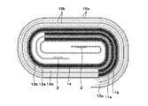
次いで、ポリマー電解質層14を形成した正極11および負極12を用い、正極12、セパレータ13a、負極12、セパレータ13bの順に積層して巻回し、図7に示すような電池素子10とする。この時、正極集電体露呈部15aおよび負極集電体露呈部15bが対向して配置され、電池素子10の外周部を1周以上覆っている。
Next, using the
このような電池素子10を、外装材であるラミネートフィルム4に収容し、電池素子10の周囲を熱溶着等で封止して電池とする。ラミネートフィルム4は、金属箔の両面が絶縁性の樹脂材料で覆われた防湿性、絶縁性を有する多層フィルムからなる。
Such a
金属箔は、外装材の強度向上の他、水分、酸素、光の進入を防ぎ内容物を守る最も重要な役割を担っており、ステンレスあるいはニッケルメッキを施した鉄等を材料として適宜用いることができるが、軽さ、伸び性、価格、加工のしやすさからアルミニウム(Al)が最も好適である。 In addition to improving the strength of the exterior material, the metal foil plays the most important role of protecting the contents by preventing the entry of moisture, oxygen, and light. It is appropriate to use stainless steel or nickel-plated iron as the material as appropriate. However, aluminum (Al) is the most suitable because of its lightness, extensibility, price, and ease of processing.
また、電池内側に位置する樹脂層は熱や超音波で溶け、互いに融着する部分であり、ポリエチレン(PE)、無軸延伸ポリプロピレン(CPP)、ポリエチレンテレフタレート(PET)、ナイロン(Ny)の他、低密度ポリエチレン(LDPE)、高密度ポリエチレン(HDPE)、直鎖状低密度ポリエチレン(LLDPE)が使用可能であり、これらから複数種類選択して用いることも可能である。 In addition, the resin layer located inside the battery is a part that melts and fuses with heat or ultrasonic waves. Other than polyethylene (PE), non-axially stretched polypropylene (CPP), polyethylene terephthalate (PET), nylon (Ny) Low density polyethylene (LDPE), high density polyethylene (HDPE), and linear low density polyethylene (LLDPE) can be used, and a plurality of types can be selected and used.
さらに、電池外側に位置する樹脂層には、電池には外観の美しさや強靱さ、柔軟性などからナイロン(Ny)、またはポリエチレンテレフタレート(PET)、ポリエチレン(PE)が用いられ、これらから複数種類選択して用いることも可能である。 Further, nylon (Ny), polyethylene terephthalate (PET), or polyethylene (PE) is used for the resin layer located outside the battery because of its beautiful appearance, toughness, and flexibility. It is also possible to select and use the type.
このようにして図1のような外観のポリマー電池が作製される。この電池では局部電池化を防ぎ、負極集電体露呈部15bで銅の析出を抑制することができる。この方法を用いた場合、ポリマー電解質14の塗布のみで問題点の解消が可能であり、製造コスト、生産タクトの観点から非常に好適である。
Thus, a polymer battery having an appearance as shown in FIG. 1 is produced. In this battery, local battery formation can be prevented, and precipitation of copper can be suppressed by the negative electrode collector exposed
また、第2の実施形態として、負極集電体12である銅箔と、ポリマー電解質14の接触を防止して銅の析出を抑制する方法が挙げられる。
In addition, as a second embodiment, there is a method in which the copper foil as the negative electrode
この方法では第1の実施形態と同様に、正極集電体11aおよび負極集電体12a上の巻回終端部が正極集電体露呈部15aおよび負極集電体露呈部15bとなるようにして正極活物質層11bおよび負極活物質層12bを設け、正極集電体露呈部15aにポリマー皮膜20を形成する。
In this method, as in the first embodiment, the winding end portions on the positive electrode
フッ素系のポリマーをNMP(N−メチル−2−ピロリドン)などの溶媒に1〜5%程度の濃度で混合し、この混合溶液を正極11の両面に設けられた正極集電体露呈部15aに塗布する。この後、120℃程度の高温で乾燥することにより、図8に示すように正極集電体露呈部15a上にポリマー皮膜20が形成される。
A fluorine-based polymer is mixed with a solvent such as NMP (N-methyl-2-pyrrolidone) at a concentration of about 1 to 5%, and this mixed solution is applied to the positive electrode current collector exposed
このとき、ポリマー皮膜20は正極活物質層11bの端部に乗せるようにして形成し、正極活物質層11bの端部付近に隙間ができないようにする。また、巻回時に負極12の端部よりも長くなるようにし、正極11および負極12が接触しないよう構成する。
At this time, the
フッ素系ポリマーとしてはポリテトラフルオロエチレン、ポリクロロトリフルオロエチレン、ポリフッ化ビニリデン、フッ化ビニリデンおよびヘキサフルオロプロピレンの共重合体、またはポリフッ化ビニルなどを用いることができる。 As the fluorine-based polymer, polytetrafluoroethylene, polychlorotrifluoroethylene, polyvinylidene fluoride, a copolymer of vinylidene fluoride and hexafluoropropylene, polyvinyl fluoride, or the like can be used.
また、銅箔との接着性を向上させるために、上述のフッ素系ポリマーに変性物質を混合することも可能である。変性物質としては、具体的に、エチレン、スチレン、ブタジエン、塩化ビニル、酢酸ビニル、アクリル酸、アクリル酸メチル、メチルビニルケトン、アクリルアミド、アクリロニトリル、塩化ビニリデン、メタクリル酸、メタクリル酸メチル、マレイン酸モノメチル、またはイソプレンなどを用いることができる。 Moreover, in order to improve adhesiveness with copper foil, it is also possible to mix a modified substance with the above-mentioned fluoropolymer. Specific examples of the modifying material include ethylene, styrene, butadiene, vinyl chloride, vinyl acetate, acrylic acid, methyl acrylate, methyl vinyl ketone, acrylamide, acrylonitrile, vinylidene chloride, methacrylic acid, methyl methacrylate, monomethyl maleate, Alternatively, isoprene or the like can be used.
このようにして作製した負極12と、正極11のそれぞれに、ポリマー電解質溶液を塗布後、常温で保存するか、もしくは乾燥工程を経てポリマー電解質層14を形成する。ポリマー電解質溶液は正極活物質11bおよび負極活物質12b上に形成すればよい。
The polymer electrolyte solution is applied to each of the
次いで、正極11、セパレータ13a、負極12、セパレータ13bを順に積層して巻回し、図9に示すような電池素子10とする。さらにこの電池素子10をラミネートフィルムにて外装し、周囲を封止して電池とした。
Subsequently, the
このように、正極および負極の接触を抑制することにより電池内部での自己放電を防止することができる。この方法では、フッ素系ポリマー混合溶液を塗布後に乾燥させるため、2〜8μm程度の非常に薄い皮膜を形成することができ、電池の体積効率を向上させる。 Thus, self-discharge inside the battery can be prevented by suppressing contact between the positive electrode and the negative electrode. In this method, since the fluoropolymer mixed solution is dried after application, a very thin film of about 2 to 8 μm can be formed, and the volume efficiency of the battery is improved.
さらに、第3の実施形態として、図10に示すように正極集電体露呈部15aを保護フィルム21で被覆し、銅箔とポリマー電解質の接触を防ぐ方法もある。保護フィルム21としては粘着テープを用いることができ、ポリマー電解質14により損傷を受けにくい材料を用いたものであれば任意のものが使用可能である。具体的には、ポリプロピレン(PP)またはポリエチレン(PE)からなる粘着テープが好適である。
Furthermore, as a third embodiment, as shown in FIG. 10, there is a method in which the positive electrode current collector exposed
これらの実施形態は単独で用いることが可能であるが、第1の実施形態および第2の実施形態または第1の実施形態および第3の実施形態を組み合わせて用いることにより、より電圧低下が起こりにくく、安全性の高い電池が得られる。 Although these embodiments can be used alone, a voltage drop occurs more by using the first embodiment and the second embodiment or the combination of the first embodiment and the third embodiment. It is difficult to obtain a highly safe battery.
以下、実施例によりこの発明を具体的に説明する。まず、以下のようにして試験用電池を作製する。 Hereinafter, the present invention will be specifically described by way of examples. First, a test battery is produced as follows.
<実施例1>
[正極の作製]
正極活物質としてLiCoO2を用いて正極を作製する。まず、LiCoO2を得るために炭酸リチウムと炭酸コバルトを0.5mol:1molの比率で混合し、900℃の空気中で5時間焼成した。次いで、得られたLiCoO291重量部と、導電剤として黒鉛6重量部と、結着剤としてポリフッ化ビニリデンとヘキサフルオロプロピレンとの共重合体10重量部とを混合して正極合剤を調製し、さらにこれをN−メチル−2−ピロリドンに分散させてスラリー状とした。
<Example 1>
[Production of positive electrode]
A positive electrode is produced using LiCoO 2 as the positive electrode active material. First, in order to obtain LiCoO 2 , lithium carbonate and cobalt carbonate were mixed at a ratio of 0.5 mol: 1 mol and fired in air at 900 ° C. for 5 hours. Next, 91 parts by weight of LiCoO 2 obtained, 6 parts by weight of graphite as a conductive agent, and 10 parts by weight of a copolymer of polyvinylidene fluoride and hexafluoropropylene as a binder are mixed to prepare a positive electrode mixture. Further, this was dispersed in N-methyl-2-pyrrolidone to form a slurry.
次いで、このスラリーを正極集電体である厚さ20μmの帯状アルミニウム箔の両面に均一に塗布した。このとき、正極集電体の一端部の両面に電池素子最外周1周分の正極集電体露呈部を設けた。次いで、乾燥工程を経てロールプレス機で圧縮成形し、正極とした。 Next, this slurry was uniformly applied to both surfaces of a 20 μm-thick strip-shaped aluminum foil as a positive electrode current collector. At this time, a positive electrode current collector exposed portion for one round of the outermost periphery of the battery element was provided on both surfaces of one end of the positive electrode current collector. Next, after a drying process, compression molding was performed with a roll press to obtain a positive electrode.
[負極の作製]
粉砕した人造黒鉛粉末90重量部と、結着剤としてポリフッ化ビニリデンとヘキサフルオロプロピレンとの共重合体10重量部とを混合して負極合剤を調製し、さらにこれをN−メチル−2−ピロリドンに分散させてスラリー状とした。
[Production of negative electrode]
90 parts by weight of the pulverized artificial graphite powder and 10 parts by weight of a copolymer of polyvinylidene fluoride and hexafluoropropylene as a binder are mixed to prepare a negative electrode mixture, which is further mixed with N-methyl-2- Dispersed in pyrrolidone to form a slurry.
次いで、このスラリーを負極集電体である厚さ10μmの帯状銅箔の両面に均一に塗布した。このとき、負極集電体の一端部の両面に電池素子最外周1周分の負極集電体露呈部を形成した。次いで、乾燥工程を経て、ロールプレス機で圧縮成形し、負極とした。 Next, this slurry was uniformly applied to both surfaces of a 10 μm-thick strip-shaped copper foil as a negative electrode current collector. At this time, a negative electrode current collector exposed portion corresponding to one round of the outermost periphery of the battery element was formed on both surfaces of one end of the negative electrode current collector. Then, after passing through a drying process, it was compression molded with a roll press to obtain a negative electrode.
[ゲル状電解質]
エチレンカーボネート(EC)50重量部とプロピレンカーボネート(PC)50重量部とを混合し、電解質塩としてLiPF6を0.7mol/kgを溶解させた後、重量平均分子量60万であるポリフッ化ビニリデンとヘキサフルオロプロピレンとの共重合体を10重量部混合した。さらに、ジメチルカーボネートを混合溶解させて電解質溶液を作製した。
[Gel electrolyte]
After mixing 50 parts by weight of ethylene carbonate (EC) and 50 parts by weight of propylene carbonate (PC) and dissolving 0.7 mol / kg of LiPF 6 as an electrolyte salt, polyvinylidene fluoride having a weight average molecular weight of 600,000 and 10 parts by weight of a copolymer with hexafluoropropylene was mixed. Furthermore, dimethyl carbonate was mixed and dissolved to prepare an electrolyte solution.
この電解質溶液を正極および負極の表面に均一に塗布し、正極活物質層および負極活物質層に含浸させた。この時、正極は正極活物質層および正極集電体露呈部が連続して覆われるように電解質溶液を塗布した。また、負極は負極活物質層上のみに電解質液を塗布した。次いで、常温で8時間放置し、ジメチルカーボネートを気化・除去してゲル状電解質膜を得た。 This electrolyte solution was uniformly applied to the surfaces of the positive electrode and the negative electrode, and impregnated into the positive electrode active material layer and the negative electrode active material layer. At this time, the electrolyte solution was applied to the positive electrode so that the positive electrode active material layer and the positive electrode current collector exposed portion were continuously covered. Moreover, the negative electrode applied the electrolyte solution only on the negative electrode active material layer. Subsequently, it was left at room temperature for 8 hours, and dimethyl carbonate was vaporized and removed to obtain a gel electrolyte membrane.
次いで、ゲル状電解質膜を形成した正極および負極を、セパレータを介して積層し、巻回して電池素子を作製した。この電池素子は、厚さ100μmのアルミラミネートフィルムにより外装し、正極端子および負極端子をアルミラミネートフィルムから導出した後、電池素子周辺を封止して図7に示すような試験用電池を作製した。なお、図7以下に示す試験用電池の断面図は実際の巻回数よりも少ない巻回数で示されており、実際は例えば10〜20回程度巻回されたものを用いる。 Next, the positive electrode and the negative electrode on which the gel electrolyte membrane was formed were laminated via a separator and wound to produce a battery element. This battery element was covered with an aluminum laminate film having a thickness of 100 μm, and after the positive electrode terminal and the negative electrode terminal were led out from the aluminum laminate film, the periphery of the battery element was sealed to produce a test battery as shown in FIG. . Note that the cross-sectional views of the test battery shown in FIG. 7 and subsequent figures are shown with a smaller number of turns than the actual number of turns, and actually, for example, those wound about 10 to 20 times are used.
<実施例2>
実施例1と同様に正極および負極を作製した後、正極両面の正極集電体露呈部にポリマー皮膜を形成する。ポリマー皮膜は、N−メチル−2−ピロリドン97重量部にポリフッ化ビニリデン3重量部を混合した溶液を正極集電体露呈部に塗布後、120℃雰囲気下で乾燥して形成した。
<Example 2>
After producing a positive electrode and a negative electrode in the same manner as in Example 1, a polymer film is formed on the positive electrode current collector exposed portions on both sides of the positive electrode. The polymer film was formed by applying a solution obtained by mixing 97 parts by weight of N-methyl-2-pyrrolidone and 3 parts by weight of polyvinylidene fluoride to the exposed part of the positive electrode current collector, and then drying in a 120 ° C. atmosphere.
正極集電体露呈部にポリマー皮膜を形成した後、正極活物質層および負極活物質層上にポリマー電解質を塗布し、正極および負極をセパレータを介して積層、巻回し、電池素子を作製した。その後電池素子をラミネートフィルムで外装して図9に示すような試験用電池とした。 After forming a polymer film on the exposed portion of the positive electrode current collector, a polymer electrolyte was applied on the positive electrode active material layer and the negative electrode active material layer, and the positive electrode and the negative electrode were stacked and wound via a separator to prepare a battery element. Thereafter, the battery element was covered with a laminate film to obtain a test battery as shown in FIG.
<実施例3>
実施例1と同様に正極および負極を作製した後、正極両面の正極集電体露呈部に保護フィルムを被覆した。保護フィルムはポリプロピレンからなる厚さ20μmの粘着テープを使用した。次いで、正極活物質層および負極活物質層上にポリマー電解質を塗布した後、正極および負極をセパレータを介して積層、巻回し、電池素子を作製した。その後電池素子をラミネートフィルムで外装して図10に示すような試験用電池とした。
<Example 3>
After producing a positive electrode and a negative electrode in the same manner as in Example 1, the protective film was coated on the positive electrode current collector exposed portions on both sides of the positive electrode. As the protective film, an adhesive tape made of polypropylene and having a thickness of 20 μm was used. Next, after applying a polymer electrolyte on the positive electrode active material layer and the negative electrode active material layer, the positive electrode and the negative electrode were laminated and wound via a separator to produce a battery element. Thereafter, the battery element was packaged with a laminate film to obtain a test battery as shown in FIG.
<比較例1>
実施例1と同様に正極および負極を作製した後、正負極共に活物質層部分のみにポリマー電解質層を形成し、セパレータを介して積層、巻回し、電池素子とした後、ラミネートフィルムで外装して図11に示すような試験用電池とした。この電池は、最外周の正極集電体露呈部および負極集電体露呈部の対向部分にセパレータのみが存在する電池である。
<Comparative Example 1>
After producing a positive electrode and a negative electrode in the same manner as in Example 1, a polymer electrolyte layer is formed only on the active material layer portion for both the positive and negative electrodes, and laminated and wound through a separator to form a battery element, which is then covered with a laminate film. Thus, a test battery as shown in FIG. 11 was obtained. This battery is a battery in which only a separator is present at a portion facing the outermost positive electrode current collector exposed portion and the negative electrode current collector exposed portion.
<比較例2>
実施例1と同様の材料を用い、正極集電体露呈部および負極集電体露呈部が設けられていない正極および負極を作製した。ポリマー電解質は正極活物質層および負極活物質層上に塗布し、セパレータを介して積層、巻回して電池素子とした後、ラミネートフィルムで外装して図12に示すような試験用電池とした。
<Comparative example 2>
Using the same material as in Example 1, a positive electrode and a negative electrode were prepared in which the positive electrode current collector exposed portion and the negative electrode current collector exposed portion were not provided. The polymer electrolyte was applied on the positive electrode active material layer and the negative electrode active material layer, laminated and wound through a separator to form a battery element, and then packaged with a laminate film to obtain a test battery as shown in FIG.
(1)釘刺し安全試験
各試験用電池をそれぞれ10個ずつ用い、25℃雰囲気下で釘刺し安全試験を行った。この試験では、各試験用電池を1Cの電流で4.5Vまで定電流充電を行った後、4.5Vでの定電圧充電を合計3時間行った。次いで各試験電池について鉄釘を6000mm/secで貫通させ、その後の電池の発熱状態を観察した。
(1) Nail penetration safety test Using 10 batteries for each test, a nail penetration safety test was conducted in an atmosphere at 25 ° C. In this test, each test battery was charged at a constant current up to 4.5 V at a current of 1 C, and then charged at a constant voltage of 4.5 V for a total of 3 hours. Next, an iron nail was passed through each test battery at 6000 mm / sec, and the subsequent heat generation state of the battery was observed.
釘刺し試験は、圧壊時や外部短絡時に比べて短絡面積が小さく電流が集中するため、急激に発熱が起こり、通常の使用条件では生じ得ないような安全性の欠如も見出しうるほどに苛酷な安全性試験である。したがって、釘刺し試験で安全性が確認できれば、異常使用時でも十分に安全性が確保されるものと考えられる。 The nail penetration test is severe enough to find a lack of safety that cannot be generated under normal use conditions because the short-circuit area is smaller and the current is concentrated than when crushing or external short-circuiting, and current is concentrated. It is a safety test. Therefore, if safety can be confirmed by a nail penetration test, it is considered that safety is sufficiently ensured even during abnormal use.
以下の表1に、釘刺し安全試験の試験結果を示す。各試験用電池は実用の観点から発熱温度が150℃未満のものを良品とし、150℃以上になった電池の個数を測定した。 Table 1 below shows the test results of the nail penetration safety test. For each test battery, a battery having an exothermic temperature of less than 150 ° C. was regarded as a non-defective product from the viewpoint of practical use, and the number of batteries having reached 150 ° C. or more was measured.

以上の結果より、電池素子最外周に正極集電体露呈部、負極集電体露呈部を対向させた構造の電池は急激な温度上昇が認められず、安全性が高いことが分かる。 From the above results, it can be seen that a battery having a structure in which the positive electrode current collector exposed portion and the negative electrode current collector exposed portion are opposed to the outermost periphery of the battery element does not show a rapid temperature rise and has high safety.
(2)内部ショート率の測定
各試験用電池をそれぞれ100個ずつ用い、ショートが発生した個数から内部ショート率を求めた。なお、内部ショートの判断基準は、各試験用電池を1Cの電流で4.2Vまで定電流充電を行った後、4.2Vでの定電圧充電を合計3時間行った。その後25℃雰囲気下で一週間保存し、電池電圧が4.10V以下に低下したものをショート発生とみなし、内部ショート率を測定した。
(2) Measurement of internal short-circuit rate 100 test batteries were used, and the internal short-circuit rate was determined from the number of short-circuits. The criteria for determining internal short-circuiting were that each test battery was charged at a constant current up to 4.2 V at a current of 1 C, and then constant voltage charging at 4.2 V was performed for a total of 3 hours. Thereafter, the sample was stored in an atmosphere at 25 ° C. for one week, and when the battery voltage decreased to 4.10 V or less, it was considered that a short circuit occurred and the internal short circuit rate was measured.
以下の表2に、内部ショート率の測定結果を示す。 Table 2 below shows the measurement results of the internal short-circuit rate.
以上の結果より、電池素子最外周の正極集電体、負極集電体の対向部にセパレータのみが存在する電池は内部ショートが発生するのに対し、正極集電体、負極集電体の対向部にポリマー電解質層やポリマー皮膜、粘着テープ、正負極活物質層が形成された電池は内部ショートの発生が見られなかった。 From the above results, the battery in which only the separator exists in the facing portion of the positive electrode current collector and the negative electrode current collector on the outermost periphery of the battery element causes an internal short circuit, whereas the positive electrode current collector and the negative electrode current collector face each other. In the battery in which the polymer electrolyte layer, the polymer film, the adhesive tape, and the positive and negative electrode active material layers were formed on the part, no internal short circuit was observed.
以上の釘刺し安全試験および内部ショート率の測定結果から、電池素子最外周部に正極集電体露呈部および負極集電体露呈部を設け、かつ負極集電体露呈部に被覆材を用いることにより、電池電圧の低下を防ぎ内部短絡などの異常時にも電池の急激な発熱を防ぐことができる。 From the above nail penetration safety test and measurement results of the internal short-circuit rate, a positive electrode current collector exposed portion and a negative electrode current collector exposed portion are provided on the outermost periphery of the battery element, and a covering material is used for the negative electrode current collector exposed portion. Accordingly, it is possible to prevent the battery voltage from being lowered and to prevent the battery from rapidly generating heat even when there is an abnormality such as an internal short circuit.
以上、この発明の実施形態について具体的に説明したが、この発明は、上述の実施形態に限定されるものではなく、この発明の技術的思想に基づく各種の変形が可能である。 As mentioned above, although embodiment of this invention was described concretely, this invention is not limited to the above-mentioned embodiment, The various deformation | transformation based on the technical idea of this invention is possible.
例えば、上述の実施形態において挙げた数値はあくまでも例に過ぎず、必要に応じてこれと異なる数値を用いてもよい。 For example, the numerical values given in the above embodiment are merely examples, and different numerical values may be used as necessary.
また、正極集電体露呈部および負極集電体露呈部を対向させた部分は、電池素子最内周部に設けても良い。この場合も、上記第1、第2および第3の実施形態の各方法により正極集電体露呈部および負極集電体露呈部を被覆することにより、電圧低下が起こりにくい電池が得られる。 Moreover, you may provide the part which made the positive electrode collector exposed part and the negative electrode collector exposed part oppose in the battery element innermost peripheral part. Also in this case, by covering the positive electrode current collector exposed portion and the negative electrode current collector exposed portion by the methods of the first, second, and third embodiments, a battery that is unlikely to cause a voltage drop is obtained.
また、セパレータを用いない電池構造としてもよい。さらに、電池素子はラミネートフィルムのみならず、電池缶で外装された場合でも適用することができる。 Moreover, it is good also as a battery structure which does not use a separator. Further, the battery element can be applied not only to a laminate film but also to a case where it is packaged with a battery can.
また、被覆材は必ずしも正極集電体露呈部に形成する必要はなく、負極集電体露呈部を完全に覆うことができれば負極に被覆材を設ける構造でも良い。 In addition, the coating material is not necessarily formed on the positive electrode current collector exposed portion, and may be configured so that the negative electrode current collector exposed portion can be completely covered.
1・・・電池
2・・・電極端子
2a・・・正極端子
2b・・・負極端子
3a,3b・・・シーラント
4・・・ラミネートフィルム
10・・・電池素子
11・・・正極
11a・・・正極集電体
11b・・・正極活物質層
12・・・負極
12a・・・負極集電体
12b・・・負極活物質層
13、13a,13b・・・セパレータ
14・・・ポリマー電解質
15a・・・正極集電体露呈部
15b・・・負極集電体露呈部
20・・・ポリマー皮膜
21・・・粘着テープ
DESCRIPTION OF
Claims (5)
上記正極および上記負極の巻回終端部に電池素子最外周1周分以上の正極集電体露呈部および負極集電体露呈部がセパレータを介して対向する集電体対向部を有し、
上記正極集電体露呈部および上記負極集電体露呈部の少なくとも一方の該正極集電体露呈部または該負極集電体露呈部と対向する部分全体が、フッ素系ポリマーを含有する皮膜もしくは保護フィルムからなる被覆材で覆われており、かつ該皮膜もしくは該保護フィルムが正極活物質層上から該正極集電体露呈部の端部を全てまたは負極活物質層上から該負極集電体露呈部の端部を全て覆うように連続して形成されたポリマー電解質で覆われており、
上記正極集電体露呈部または上記負極集電体露呈部のうち、上記電池素子の最外層として露出する一部分には、上記被覆材が設けられていない
ポリマー電池。 In a polymer battery having a battery element produced by laminating and winding a positive electrode and a negative electrode with a polymer electrolyte formed on the surface,
Has a current collector facing portion of the positive electrode and the winding end positive electrode current collector exposed portion of the above one round cell element outermost to end and the negative electrode current collector exposed portion of the negative electrode are opposed through a separator,
The positive electrode current collector exposed portion and the negative electrode current collector exposed portion at least one of the positive electrode current collector exposed portion or the entire portion facing the negative electrode current collector exposed portion is a coating or protection containing a fluoropolymer. The coating film or the protective film is covered with a coating material made of a film, and the end of the positive electrode current collector exposed portion is entirely exposed from the positive electrode active material layer or the negative electrode current collector exposed from the negative electrode active material layer. It is covered with a polymer electrolyte that is continuously formed so as to cover all ends of the part,
The polymer battery, wherein the covering material is not provided on a part of the positive electrode current collector exposed portion or the negative electrode current collector exposed portion exposed as the outermost layer of the battery element .
上記正極および上記負極の巻回終端部に電池素子最外周1周分以上の正極集電体露呈部および負極集電体露呈部がセパレータを介して対向する集電体対向部を有し、
上記正極集電体露呈部および上記負極集電体露呈部の少なくとも一方の該正極集電体露呈部または該負極集電体露呈部と対向する部分全体が、フッ素系ポリマーを含有する皮膜もしくは保護フィルムからなる被覆材で覆われており、
上記正極集電体露呈部または上記負極集電体露呈部のうち、上記電池素子の最外層として露出する一部分には、上記被覆材が設けられていない
ポリマー電池。 In a polymer battery having a battery element produced by laminating and winding a positive electrode and a negative electrode with a polymer electrolyte formed on the surface,
Has a current collector facing portion of the positive electrode and the winding end positive electrode current collector exposed portion of the above one round cell element outermost to end and the negative electrode current collector exposed portion of the negative electrode are opposed through a separator,
The positive electrode current collector exposed portion and the negative electrode current collector exposed portion at least one of the positive electrode current collector exposed portion or the entire portion facing the negative electrode current collector exposed portion is a coating or protection containing a fluoropolymer. It is covered with a coating made of film ,
The polymer battery, wherein the covering material is not provided on a part of the positive electrode current collector exposed portion or the negative electrode current collector exposed portion exposed as the outermost layer of the battery element .
請求項2に記載のポリマー電池。The polymer battery according to claim 2.
請求項3に記載のポリマー電池。 The fluorine-based polymer, it contains denaturing agents
Polymer battery according to 請 Motomeko 3.
請求項4に記載のポリマー電池。The polymer battery according to claim 4.
Priority Applications (1)
| Application Number | Priority Date | Filing Date | Title |
|---|---|---|---|
| JP2005107177A JP4815845B2 (en) | 2005-04-04 | 2005-04-04 | Polymer battery |
Applications Claiming Priority (1)
| Application Number | Priority Date | Filing Date | Title |
|---|---|---|---|
| JP2005107177A JP4815845B2 (en) | 2005-04-04 | 2005-04-04 | Polymer battery |
Publications (2)
| Publication Number | Publication Date |
|---|---|
| JP2006286496A JP2006286496A (en) | 2006-10-19 |
| JP4815845B2 true JP4815845B2 (en) | 2011-11-16 |
Family
ID=37408174
Family Applications (1)
| Application Number | Title | Priority Date | Filing Date |
|---|---|---|---|
| JP2005107177A Expired - Fee Related JP4815845B2 (en) | 2005-04-04 | 2005-04-04 | Polymer battery |
Country Status (1)
| Country | Link |
|---|---|
| JP (1) | JP4815845B2 (en) |
Families Citing this family (7)
| Publication number | Priority date | Publication date | Assignee | Title |
|---|---|---|---|---|
| JP2008192496A (en) * | 2007-02-06 | 2008-08-21 | Matsushita Electric Ind Co Ltd | Internal short circuit evaluation method of battery, battery, battery pack, and their manufacturing method |
| JP6398170B2 (en) | 2013-10-11 | 2018-10-03 | 株式会社村田製作所 | Lithium ion secondary battery, battery pack, electric vehicle, power storage system, electric tool and electronic device |
| JP6398171B2 (en) | 2013-10-11 | 2018-10-03 | 株式会社村田製作所 | Lithium ion secondary battery, battery pack, electric vehicle, power storage system, electric tool and electronic device |
| JP6540476B2 (en) * | 2015-11-27 | 2019-07-10 | トヨタ自動車株式会社 | Secondary battery having an electrode body |
| KR102277352B1 (en) * | 2016-08-24 | 2021-07-14 | 삼성에스디아이 주식회사 | Electrode assembly and rechargeable battery including the same |
| EP3940855A4 (en) * | 2020-05-20 | 2022-04-20 | Ningde Amperex Technology Ltd. | Electrode assembly and battery |
| WO2023199825A1 (en) * | 2022-04-14 | 2023-10-19 | パナソニックIpマネジメント株式会社 | Non-aqueous electrolyte secondary battery |
Family Cites Families (4)
| Publication number | Priority date | Publication date | Assignee | Title |
|---|---|---|---|---|
| JP3200340B2 (en) * | 1994-09-27 | 2001-08-20 | 旭化成株式会社 | Non-aqueous battery |
| JPH11144765A (en) * | 1997-11-11 | 1999-05-28 | Toray Ind Inc | Nonaqueous electrolyte secondary battery |
| JP4055345B2 (en) * | 1999-09-30 | 2008-03-05 | ソニー株式会社 | Solid electrolyte battery |
| JP4281329B2 (en) * | 2002-11-08 | 2009-06-17 | ソニー株式会社 | Non-aqueous electrolyte battery |
-
2005
- 2005-04-04 JP JP2005107177A patent/JP4815845B2/en not_active Expired - Fee Related
Also Published As
| Publication number | Publication date |
|---|---|
| JP2006286496A (en) | 2006-10-19 |
Similar Documents
| Publication | Publication Date | Title |
|---|---|---|
| JP4883025B2 (en) | Secondary battery | |
| CN105703006B (en) | Electrolyte and negative pole structure | |
| JP3982165B2 (en) | Solid electrolyte battery | |
| US6632256B1 (en) | Method for manufacturing a non-aqueous-gel-electrolyte battery | |
| JP5264099B2 (en) | Nonaqueous electrolyte secondary battery | |
| JP2002063938A (en) | Secondary battery and its manufacturing method | |
| US20100119940A1 (en) | Secondary battery | |
| JP4952658B2 (en) | Battery element exterior member and non-aqueous electrolyte secondary battery using the same | |
| JP4872950B2 (en) | Nonaqueous electrolyte secondary battery | |
| CN102187497A (en) | Electrode plate for nonaqueous electrolyte secondary battery, and nonaqueous electrolyte secondary battery | |
| CN109449478A (en) | Electrochemical appliance | |
| JP4815845B2 (en) | Polymer battery | |
| JP4992203B2 (en) | Lithium ion secondary battery | |
| JP2008047398A (en) | Nonaqueous electrolyte secondary battery | |
| JP4297166B2 (en) | Nonaqueous electrolyte secondary battery | |
| JP2010049909A (en) | Nonaqueous electrolyte secondary battery | |
| JP4551539B2 (en) | Nonaqueous electrolyte secondary battery | |
| JP4741526B2 (en) | Nonaqueous electrolyte secondary battery | |
| JP5213003B2 (en) | Nonaqueous electrolyte secondary battery | |
| JP4142921B2 (en) | Lithium ion secondary battery | |
| JP4449214B2 (en) | Non-aqueous electrolyte battery | |
| JP5380908B2 (en) | Winding electrode body and non-aqueous electrolyte secondary battery | |
| KR20090045069A (en) | Secondary battery | |
| JP4782266B2 (en) | Non-aqueous electrolyte battery | |
| JP2007134149A (en) | Nonaqueous electrolyte battery |
Legal Events
| Date | Code | Title | Description |
|---|---|---|---|
| A621 | Written request for application examination |
Free format text: JAPANESE INTERMEDIATE CODE: A621 Effective date: 20080305 |
|
| A977 | Report on retrieval |
Free format text: JAPANESE INTERMEDIATE CODE: A971007 Effective date: 20101122 |
|
| A131 | Notification of reasons for refusal |
Free format text: JAPANESE INTERMEDIATE CODE: A131 Effective date: 20101130 |
|
| A521 | Written amendment |
Free format text: JAPANESE INTERMEDIATE CODE: A523 Effective date: 20110126 |
|
| TRDD | Decision of grant or rejection written | ||
| A01 | Written decision to grant a patent or to grant a registration (utility model) |
Free format text: JAPANESE INTERMEDIATE CODE: A01 Effective date: 20110802 |
|
| A01 | Written decision to grant a patent or to grant a registration (utility model) |
Free format text: JAPANESE INTERMEDIATE CODE: A01 |
|
| A61 | First payment of annual fees (during grant procedure) |
Free format text: JAPANESE INTERMEDIATE CODE: A61 Effective date: 20110815 |
|
| FPAY | Renewal fee payment (event date is renewal date of database) |
Free format text: PAYMENT UNTIL: 20140909 Year of fee payment: 3 |
|
| FPAY | Renewal fee payment (event date is renewal date of database) |
Free format text: PAYMENT UNTIL: 20140909 Year of fee payment: 3 |
|
| R250 | Receipt of annual fees |
Free format text: JAPANESE INTERMEDIATE CODE: R250 |
|
| LAPS | Cancellation because of no payment of annual fees |