JP3899499B2 - Non-aqueous electrolyte battery - Google Patents
Non-aqueous electrolyte battery Download PDFInfo
- Publication number
- JP3899499B2 JP3899499B2 JP32851298A JP32851298A JP3899499B2 JP 3899499 B2 JP3899499 B2 JP 3899499B2 JP 32851298 A JP32851298 A JP 32851298A JP 32851298 A JP32851298 A JP 32851298A JP 3899499 B2 JP3899499 B2 JP 3899499B2
- Authority
- JP
- Japan
- Prior art keywords
- battery
- electrolyte battery
- control circuit
- heat
- battery according
- Prior art date
- Legal status (The legal status is an assumption and is not a legal conclusion. Google has not performed a legal analysis and makes no representation as to the accuracy of the status listed.)
- Expired - Lifetime
Links
- 239000011255 nonaqueous electrolyte Substances 0.000 title claims description 31
- 238000003466 welding Methods 0.000 claims description 21
- 239000011245 gel electrolyte Substances 0.000 claims description 20
- 239000000463 material Substances 0.000 claims description 20
- 229920000642 polymer Polymers 0.000 claims description 20
- 239000007784 solid electrolyte Substances 0.000 claims description 16
- 239000005001 laminate film Substances 0.000 claims description 14
- 229910052744 lithium Inorganic materials 0.000 claims description 9
- WHXSMMKQMYFTQS-UHFFFAOYSA-N Lithium Chemical compound [Li] WHXSMMKQMYFTQS-UHFFFAOYSA-N 0.000 claims description 8
- 229910003002 lithium salt Inorganic materials 0.000 claims description 8
- 159000000002 lithium salts Chemical class 0.000 claims description 8
- 239000003792 electrolyte Substances 0.000 claims description 6
- 239000002131 composite material Substances 0.000 claims description 5
- 239000003575 carbonaceous material Substances 0.000 claims description 4
- 239000005022 packaging material Substances 0.000 claims description 4
- 239000011159 matrix material Substances 0.000 claims description 3
- 239000004033 plastic Substances 0.000 claims description 3
- 229920003023 plastic Polymers 0.000 claims description 3
- 229910052723 transition metal Inorganic materials 0.000 claims description 3
- 150000003624 transition metals Chemical class 0.000 claims description 3
- XLYOFNOQVPJJNP-UHFFFAOYSA-N water Substances O XLYOFNOQVPJJNP-UHFFFAOYSA-N 0.000 claims 1
- 239000007774 positive electrode material Substances 0.000 description 11
- 229920005569 poly(vinylidene fluoride-co-hexafluoropropylene) Polymers 0.000 description 8
- HBBGRARXTFLTSG-UHFFFAOYSA-N Lithium ion Chemical compound [Li+] HBBGRARXTFLTSG-UHFFFAOYSA-N 0.000 description 6
- 230000017525 heat dissipation Effects 0.000 description 6
- 229910001416 lithium ion Inorganic materials 0.000 description 6
- 239000007773 negative electrode material Substances 0.000 description 6
- 239000004014 plasticizer Substances 0.000 description 6
- PXHVJJICTQNCMI-UHFFFAOYSA-N Nickel Chemical compound [Ni] PXHVJJICTQNCMI-UHFFFAOYSA-N 0.000 description 5
- 230000000694 effects Effects 0.000 description 5
- 238000000034 method Methods 0.000 description 5
- OKTJSMMVPCPJKN-UHFFFAOYSA-N Carbon Chemical compound [C] OKTJSMMVPCPJKN-UHFFFAOYSA-N 0.000 description 4
- SECXISVLQFMRJM-UHFFFAOYSA-N N-Methylpyrrolidone Chemical compound CN1CCCC1=O SECXISVLQFMRJM-UHFFFAOYSA-N 0.000 description 4
- 229910052782 aluminium Inorganic materials 0.000 description 4
- XAGFODPZIPBFFR-UHFFFAOYSA-N aluminium Chemical compound [Al] XAGFODPZIPBFFR-UHFFFAOYSA-N 0.000 description 4
- 239000011230 binding agent Substances 0.000 description 4
- 150000001875 compounds Chemical class 0.000 description 4
- -1 lithium tetrafluoroborate Chemical compound 0.000 description 4
- 239000002002 slurry Substances 0.000 description 4
- RYGMFSIKBFXOCR-UHFFFAOYSA-N Copper Chemical compound [Cu] RYGMFSIKBFXOCR-UHFFFAOYSA-N 0.000 description 3
- YCKRFDGAMUMZLT-UHFFFAOYSA-N Fluorine atom Chemical compound [F] YCKRFDGAMUMZLT-UHFFFAOYSA-N 0.000 description 3
- 229910012851 LiCoO 2 Inorganic materials 0.000 description 3
- 238000011156 evaluation Methods 0.000 description 3
- 239000012467 final product Substances 0.000 description 3
- 239000011737 fluorine Substances 0.000 description 3
- 229910052731 fluorine Inorganic materials 0.000 description 3
- 239000011888 foil Substances 0.000 description 3
- 239000000203 mixture Substances 0.000 description 3
- 229910052759 nickel Inorganic materials 0.000 description 3
- 229920000131 polyvinylidene Polymers 0.000 description 3
- 238000007789 sealing Methods 0.000 description 3
- 238000012360 testing method Methods 0.000 description 3
- RTZKZFJDLAIYFH-UHFFFAOYSA-N Diethyl ether Chemical compound CCOCC RTZKZFJDLAIYFH-UHFFFAOYSA-N 0.000 description 2
- KMTRUDSVKNLOMY-UHFFFAOYSA-N Ethylene carbonate Chemical compound O=C1OCCO1 KMTRUDSVKNLOMY-UHFFFAOYSA-N 0.000 description 2
- XPDWGBQVDMORPB-UHFFFAOYSA-N Fluoroform Chemical compound FC(F)F XPDWGBQVDMORPB-UHFFFAOYSA-N 0.000 description 2
- 229910013870 LiPF 6 Inorganic materials 0.000 description 2
- 229920003171 Poly (ethylene oxide) Polymers 0.000 description 2
- 150000004649 carbonic acid derivatives Chemical class 0.000 description 2
- 239000006258 conductive agent Substances 0.000 description 2
- 239000011889 copper foil Substances 0.000 description 2
- 229920006037 cross link polymer Polymers 0.000 description 2
- 238000007599 discharging Methods 0.000 description 2
- 238000001035 drying Methods 0.000 description 2
- 150000002642 lithium compounds Chemical class 0.000 description 2
- HSZCZNFXUDYRKD-UHFFFAOYSA-M lithium iodide Chemical compound [Li+].[I-] HSZCZNFXUDYRKD-UHFFFAOYSA-M 0.000 description 2
- IIPYXGDZVMZOAP-UHFFFAOYSA-N lithium nitrate Chemical compound [Li+].[O-][N+]([O-])=O IIPYXGDZVMZOAP-UHFFFAOYSA-N 0.000 description 2
- 238000004519 manufacturing process Methods 0.000 description 2
- 229910052751 metal Inorganic materials 0.000 description 2
- 239000002184 metal Substances 0.000 description 2
- 229910044991 metal oxide Inorganic materials 0.000 description 2
- 229910052976 metal sulfide Inorganic materials 0.000 description 2
- 239000002985 plastic film Substances 0.000 description 2
- 229920006255 plastic film Polymers 0.000 description 2
- RUOJZAUFBMNUDX-UHFFFAOYSA-N propylene carbonate Chemical compound CC1COC(=O)O1 RUOJZAUFBMNUDX-UHFFFAOYSA-N 0.000 description 2
- 150000003839 salts Chemical class 0.000 description 2
- 239000002904 solvent Substances 0.000 description 2
- 239000000758 substrate Substances 0.000 description 2
- 238000004804 winding Methods 0.000 description 2
- WBPWDGRYHFQTRC-UHFFFAOYSA-N 2-ethoxycyclohexan-1-one Chemical compound CCOC1CCCCC1=O WBPWDGRYHFQTRC-UHFFFAOYSA-N 0.000 description 1
- CBQMKYHLDADRLN-UHFFFAOYSA-N 7-methylhypoxanthine Chemical compound N1C=NC(=O)C2=C1N=CN2C CBQMKYHLDADRLN-UHFFFAOYSA-N 0.000 description 1
- NLHHRLWOUZZQLW-UHFFFAOYSA-N Acrylonitrile Chemical compound C=CC#N NLHHRLWOUZZQLW-UHFFFAOYSA-N 0.000 description 1
- 229920000049 Carbon (fiber) Polymers 0.000 description 1
- OIFBSDVPJOWBCH-UHFFFAOYSA-N Diethyl carbonate Chemical compound CCOC(=O)OCC OIFBSDVPJOWBCH-UHFFFAOYSA-N 0.000 description 1
- KRHYYFGTRYWZRS-UHFFFAOYSA-M Fluoride anion Chemical compound [F-] KRHYYFGTRYWZRS-UHFFFAOYSA-M 0.000 description 1
- 229910010238 LiAlCl 4 Inorganic materials 0.000 description 1
- 229910015015 LiAsF 6 Inorganic materials 0.000 description 1
- 229910013063 LiBF 4 Inorganic materials 0.000 description 1
- 229910015118 LiMO Inorganic materials 0.000 description 1
- 229910015643 LiMn 2 O 4 Inorganic materials 0.000 description 1
- 229910013716 LiNi Inorganic materials 0.000 description 1
- 229910013290 LiNiO 2 Inorganic materials 0.000 description 1
- 229920001166 Poly(vinylidene fluoride-co-trifluoroethylene) Polymers 0.000 description 1
- XUIMIQQOPSSXEZ-UHFFFAOYSA-N Silicon Chemical compound [Si] XUIMIQQOPSSXEZ-UHFFFAOYSA-N 0.000 description 1
- 229910006404 SnO 2 Inorganic materials 0.000 description 1
- RTAQQCXQSZGOHL-UHFFFAOYSA-N Titanium Chemical compound [Ti] RTAQQCXQSZGOHL-UHFFFAOYSA-N 0.000 description 1
- 150000001252 acrylic acid derivatives Chemical class 0.000 description 1
- NIXOWILDQLNWCW-UHFFFAOYSA-N acrylic acid group Chemical group C(C=C)(=O)O NIXOWILDQLNWCW-UHFFFAOYSA-N 0.000 description 1
- 239000011149 active material Substances 0.000 description 1
- 239000000853 adhesive Substances 0.000 description 1
- 230000001070 adhesive effect Effects 0.000 description 1
- 229910045601 alloy Inorganic materials 0.000 description 1
- 239000000956 alloy Substances 0.000 description 1
- HSFWRNGVRCDJHI-UHFFFAOYSA-N alpha-acetylene Natural products C#C HSFWRNGVRCDJHI-UHFFFAOYSA-N 0.000 description 1
- 238000005452 bending Methods 0.000 description 1
- 239000004917 carbon fiber Substances 0.000 description 1
- 238000003763 carbonization Methods 0.000 description 1
- 229910021446 cobalt carbonate Inorganic materials 0.000 description 1
- ZOTKGJBKKKVBJZ-UHFFFAOYSA-L cobalt(2+);carbonate Chemical compound [Co+2].[O-]C([O-])=O ZOTKGJBKKKVBJZ-UHFFFAOYSA-L 0.000 description 1
- 239000000571 coke Substances 0.000 description 1
- 230000000052 comparative effect Effects 0.000 description 1
- 239000000470 constituent Substances 0.000 description 1
- 229910052802 copper Inorganic materials 0.000 description 1
- 239000010949 copper Substances 0.000 description 1
- 239000002537 cosmetic Substances 0.000 description 1
- 238000004132 cross linking Methods 0.000 description 1
- 230000006866 deterioration Effects 0.000 description 1
- IVEBINIAEMFPBH-UHFFFAOYSA-L dilithium;bromide;chloride Chemical compound [Li+].[Li+].[Cl-].[Br-] IVEBINIAEMFPBH-UHFFFAOYSA-L 0.000 description 1
- IEJIGPNLZYLLBP-UHFFFAOYSA-N dimethyl carbonate Chemical compound COC(=O)OC IEJIGPNLZYLLBP-UHFFFAOYSA-N 0.000 description 1
- 150000002148 esters Chemical class 0.000 description 1
- 150000002170 ethers Chemical class 0.000 description 1
- 238000000605 extraction Methods 0.000 description 1
- 238000010304 firing Methods 0.000 description 1
- 229920002313 fluoropolymer Polymers 0.000 description 1
- 239000004811 fluoropolymer Substances 0.000 description 1
- 239000007849 furan resin Substances 0.000 description 1
- 229910002804 graphite Inorganic materials 0.000 description 1
- 239000010439 graphite Substances 0.000 description 1
- 239000007770 graphite material Substances 0.000 description 1
- 150000002641 lithium Chemical class 0.000 description 1
- XIXADJRWDQXREU-UHFFFAOYSA-M lithium acetate Chemical compound [Li+].CC([O-])=O XIXADJRWDQXREU-UHFFFAOYSA-M 0.000 description 1
- XGZVUEUWXADBQD-UHFFFAOYSA-L lithium carbonate Chemical compound [Li+].[Li+].[O-]C([O-])=O XGZVUEUWXADBQD-UHFFFAOYSA-L 0.000 description 1
- 229910052808 lithium carbonate Inorganic materials 0.000 description 1
- XQHAGELNRSUUGU-UHFFFAOYSA-M lithium chlorate Chemical compound [Li+].[O-]Cl(=O)=O XQHAGELNRSUUGU-UHFFFAOYSA-M 0.000 description 1
- MHCFAGZWMAWTNR-UHFFFAOYSA-M lithium perchlorate Chemical compound [Li+].[O-]Cl(=O)(=O)=O MHCFAGZWMAWTNR-UHFFFAOYSA-M 0.000 description 1
- 229910001486 lithium perchlorate Inorganic materials 0.000 description 1
- 229910001496 lithium tetrafluoroborate Inorganic materials 0.000 description 1
- 230000014759 maintenance of location Effects 0.000 description 1
- 229910052748 manganese Inorganic materials 0.000 description 1
- 238000005259 measurement Methods 0.000 description 1
- 150000002734 metacrylic acid derivatives Chemical class 0.000 description 1
- 150000004706 metal oxides Chemical class 0.000 description 1
- 239000011331 needle coke Substances 0.000 description 1
- 229910021470 non-graphitizable carbon Inorganic materials 0.000 description 1
- 229920000620 organic polymer Polymers 0.000 description 1
- 230000003647 oxidation Effects 0.000 description 1
- 238000007254 oxidation reaction Methods 0.000 description 1
- 230000035515 penetration Effects 0.000 description 1
- 239000002006 petroleum coke Substances 0.000 description 1
- 239000005011 phenolic resin Substances 0.000 description 1
- 239000006253 pitch coke Substances 0.000 description 1
- 229920002627 poly(phosphazenes) Polymers 0.000 description 1
- 229920001197 polyacetylene Polymers 0.000 description 1
- 239000005518 polymer electrolyte Substances 0.000 description 1
- 239000002861 polymer material Substances 0.000 description 1
- 229920000193 polymethacrylate Polymers 0.000 description 1
- 229920001451 polypropylene glycol Polymers 0.000 description 1
- 229920000128 polypyrrole Polymers 0.000 description 1
- 229920002981 polyvinylidene fluoride Polymers 0.000 description 1
- 238000012545 processing Methods 0.000 description 1
- 239000002296 pyrolytic carbon Substances 0.000 description 1
- 238000011160 research Methods 0.000 description 1
- 238000012827 research and development Methods 0.000 description 1
- 230000000630 rising effect Effects 0.000 description 1
- 229910052710 silicon Inorganic materials 0.000 description 1
- 239000010703 silicon Substances 0.000 description 1
- 229910000679 solder Inorganic materials 0.000 description 1
- 125000000472 sulfonyl group Chemical group *S(*)(=O)=O 0.000 description 1
- 239000010936 titanium Substances 0.000 description 1
- 229910052719 titanium Inorganic materials 0.000 description 1
Images


Classifications
-
- H—ELECTRICITY
- H01—ELECTRIC ELEMENTS
- H01M—PROCESSES OR MEANS, e.g. BATTERIES, FOR THE DIRECT CONVERSION OF CHEMICAL ENERGY INTO ELECTRICAL ENERGY
- H01M50/00—Constructional details or processes of manufacture of the non-active parts of electrochemical cells other than fuel cells, e.g. hybrid cells
- H01M50/10—Primary casings; Jackets or wrappings
- H01M50/172—Arrangements of electric connectors penetrating the casing
-
- H—ELECTRICITY
- H01—ELECTRIC ELEMENTS
- H01M—PROCESSES OR MEANS, e.g. BATTERIES, FOR THE DIRECT CONVERSION OF CHEMICAL ENERGY INTO ELECTRICAL ENERGY
- H01M10/00—Secondary cells; Manufacture thereof
- H01M10/04—Construction or manufacture in general
- H01M10/0436—Small-sized flat cells or batteries for portable equipment
-
- H—ELECTRICITY
- H01—ELECTRIC ELEMENTS
- H01M—PROCESSES OR MEANS, e.g. BATTERIES, FOR THE DIRECT CONVERSION OF CHEMICAL ENERGY INTO ELECTRICAL ENERGY
- H01M10/00—Secondary cells; Manufacture thereof
- H01M10/05—Accumulators with non-aqueous electrolyte
- H01M10/052—Li-accumulators
- H01M10/0525—Rocking-chair batteries, i.e. batteries with lithium insertion or intercalation in both electrodes; Lithium-ion batteries
-
- H—ELECTRICITY
- H01—ELECTRIC ELEMENTS
- H01M—PROCESSES OR MEANS, e.g. BATTERIES, FOR THE DIRECT CONVERSION OF CHEMICAL ENERGY INTO ELECTRICAL ENERGY
- H01M10/00—Secondary cells; Manufacture thereof
- H01M10/05—Accumulators with non-aqueous electrolyte
- H01M10/058—Construction or manufacture
- H01M10/0585—Construction or manufacture of accumulators having only flat construction elements, i.e. flat positive electrodes, flat negative electrodes and flat separators
-
- H—ELECTRICITY
- H01—ELECTRIC ELEMENTS
- H01M—PROCESSES OR MEANS, e.g. BATTERIES, FOR THE DIRECT CONVERSION OF CHEMICAL ENERGY INTO ELECTRICAL ENERGY
- H01M10/00—Secondary cells; Manufacture thereof
- H01M10/42—Methods or arrangements for servicing or maintenance of secondary cells or secondary half-cells
- H01M10/425—Structural combination with electronic components, e.g. electronic circuits integrated to the outside of the casing
- H01M10/4257—Smart batteries, e.g. electronic circuits inside the housing of the cells or batteries
-
- H—ELECTRICITY
- H01—ELECTRIC ELEMENTS
- H01M—PROCESSES OR MEANS, e.g. BATTERIES, FOR THE DIRECT CONVERSION OF CHEMICAL ENERGY INTO ELECTRICAL ENERGY
- H01M10/00—Secondary cells; Manufacture thereof
- H01M10/42—Methods or arrangements for servicing or maintenance of secondary cells or secondary half-cells
- H01M10/48—Accumulators combined with arrangements for measuring, testing or indicating the condition of cells, e.g. the level or density of the electrolyte
-
- H—ELECTRICITY
- H01—ELECTRIC ELEMENTS
- H01M—PROCESSES OR MEANS, e.g. BATTERIES, FOR THE DIRECT CONVERSION OF CHEMICAL ENERGY INTO ELECTRICAL ENERGY
- H01M50/00—Constructional details or processes of manufacture of the non-active parts of electrochemical cells other than fuel cells, e.g. hybrid cells
- H01M50/10—Primary casings; Jackets or wrappings
- H01M50/116—Primary casings; Jackets or wrappings characterised by the material
- H01M50/117—Inorganic material
- H01M50/119—Metals
-
- H—ELECTRICITY
- H01—ELECTRIC ELEMENTS
- H01M—PROCESSES OR MEANS, e.g. BATTERIES, FOR THE DIRECT CONVERSION OF CHEMICAL ENERGY INTO ELECTRICAL ENERGY
- H01M50/00—Constructional details or processes of manufacture of the non-active parts of electrochemical cells other than fuel cells, e.g. hybrid cells
- H01M50/10—Primary casings; Jackets or wrappings
- H01M50/116—Primary casings; Jackets or wrappings characterised by the material
- H01M50/121—Organic material
-
- H—ELECTRICITY
- H01—ELECTRIC ELEMENTS
- H01M—PROCESSES OR MEANS, e.g. BATTERIES, FOR THE DIRECT CONVERSION OF CHEMICAL ENERGY INTO ELECTRICAL ENERGY
- H01M50/00—Constructional details or processes of manufacture of the non-active parts of electrochemical cells other than fuel cells, e.g. hybrid cells
- H01M50/10—Primary casings; Jackets or wrappings
- H01M50/116—Primary casings; Jackets or wrappings characterised by the material
- H01M50/124—Primary casings; Jackets or wrappings characterised by the material having a layered structure
-
- H—ELECTRICITY
- H01—ELECTRIC ELEMENTS
- H01M—PROCESSES OR MEANS, e.g. BATTERIES, FOR THE DIRECT CONVERSION OF CHEMICAL ENERGY INTO ELECTRICAL ENERGY
- H01M50/00—Constructional details or processes of manufacture of the non-active parts of electrochemical cells other than fuel cells, e.g. hybrid cells
- H01M50/50—Current conducting connections for cells or batteries
- H01M50/572—Means for preventing undesired use or discharge
-
- H—ELECTRICITY
- H01—ELECTRIC ELEMENTS
- H01M—PROCESSES OR MEANS, e.g. BATTERIES, FOR THE DIRECT CONVERSION OF CHEMICAL ENERGY INTO ELECTRICAL ENERGY
- H01M6/00—Primary cells; Manufacture thereof
- H01M6/14—Cells with non-aqueous electrolyte
- H01M6/16—Cells with non-aqueous electrolyte with organic electrolyte
-
- H—ELECTRICITY
- H01—ELECTRIC ELEMENTS
- H01M—PROCESSES OR MEANS, e.g. BATTERIES, FOR THE DIRECT CONVERSION OF CHEMICAL ENERGY INTO ELECTRICAL ENERGY
- H01M6/00—Primary cells; Manufacture thereof
- H01M6/40—Printed batteries, e.g. thin film batteries
-
- Y—GENERAL TAGGING OF NEW TECHNOLOGICAL DEVELOPMENTS; GENERAL TAGGING OF CROSS-SECTIONAL TECHNOLOGIES SPANNING OVER SEVERAL SECTIONS OF THE IPC; TECHNICAL SUBJECTS COVERED BY FORMER USPC CROSS-REFERENCE ART COLLECTIONS [XRACs] AND DIGESTS
- Y02—TECHNOLOGIES OR APPLICATIONS FOR MITIGATION OR ADAPTATION AGAINST CLIMATE CHANGE
- Y02E—REDUCTION OF GREENHOUSE GAS [GHG] EMISSIONS, RELATED TO ENERGY GENERATION, TRANSMISSION OR DISTRIBUTION
- Y02E60/00—Enabling technologies; Technologies with a potential or indirect contribution to GHG emissions mitigation
- Y02E60/10—Energy storage using batteries
-
- Y—GENERAL TAGGING OF NEW TECHNOLOGICAL DEVELOPMENTS; GENERAL TAGGING OF CROSS-SECTIONAL TECHNOLOGIES SPANNING OVER SEVERAL SECTIONS OF THE IPC; TECHNICAL SUBJECTS COVERED BY FORMER USPC CROSS-REFERENCE ART COLLECTIONS [XRACs] AND DIGESTS
- Y02—TECHNOLOGIES OR APPLICATIONS FOR MITIGATION OR ADAPTATION AGAINST CLIMATE CHANGE
- Y02P—CLIMATE CHANGE MITIGATION TECHNOLOGIES IN THE PRODUCTION OR PROCESSING OF GOODS
- Y02P70/00—Climate change mitigation technologies in the production process for final industrial or consumer products
- Y02P70/50—Manufacturing or production processes characterised by the final manufactured product
Landscapes
- Chemical & Material Sciences (AREA)
- Chemical Kinetics & Catalysis (AREA)
- Electrochemistry (AREA)
- General Chemical & Material Sciences (AREA)
- Engineering & Computer Science (AREA)
- Manufacturing & Machinery (AREA)
- Inorganic Chemistry (AREA)
- Microelectronics & Electronic Packaging (AREA)
- Materials Engineering (AREA)
- Secondary Cells (AREA)
- Sealing Battery Cases Or Jackets (AREA)
- Connection Of Batteries Or Terminals (AREA)
Description
【0001】
【発明の属する技術分野】
本発明は、ラミネートフィルムからなる外装材に電池素子を収容してなる非水電解質電池に関するものであり、特に、ゲル電解質電池、固体電解質電池等における体積エネルギー密度の改良に関するものである。
【0002】
【従来の技術】
近年、カメラ一体型VTR、携帯電話、携帯用コンピューター等のポータブル電子機器が多く登場し、その小型軽量化が図られている。そしてこれらの電子機器のポータブル電源として、電池、特に二次電池、なかでも非水電解質二次電池(いわゆるリチウムイオン電池)について、薄型や折り曲げ可能な電池の研究開発が活発に進められている。
【0003】
このような形状自在な電池の電解質として固体化した電解液の研究は盛んであり、特に可塑剤を含んだ固体電解質であるゲル状の電解質や高分子にリチウム塩を溶かし込んだ高分子固体電解質が注目を浴びている。
【0004】
一方で、こうした電池の薄型軽量というメリットを生かすべく、プラスチックフィルムやプラスチックフィルムと金属を張り合わせたいわゆるラミネートフィルムを用いて封入するタイプの電池が種々検討されている。
【0005】
【発明が解決しようとする課題】
ところで、例えば二次電池の場合、充放電を制御するための制御回路を電池周辺に配置する必要があり、この充放電制御回路を搭載しつつも体積効率を向上させるような構造が要求される。
【0006】
また、上記構造の電池では、制御回路を含めて電池全体が耐衝撃性を有すること、ラミネートフィルムからなる電池外寸法で体積エネルギー密度を定義したときの効率を高くすること、放熱特性を向上させて電池実使用時の性能に関する項目である充放電サイクル寿命を向上させること等、電池特性を多面的に検討することが要求されている。
【0007】
そこで、本発明は、かかる従来の実情に鑑みて提案されたものであり、制御回路を搭載しながらも、体積効率の高い非水電解質電池を提供することを目的とする。
【0008】
また、本発明は、耐衝撃性や放熱特性に優れるとともに、電池実使用時の性能に関する項目である充放電サイクル寿命が長い非水電解質電池を提供することを目的とする。
【0009】
さらに、本発明は、生産性に優れた非水電解質電池を提供することを目的とする。
【0010】
【課題を解決するための手段】
上記目的を達成するために、本発明は、ラミネートフィルムからなる外装材に電池素子が収容され、熱溶着により封入されるとともに、上記電池素子を構成する各電極と導通される電極端子リードが熱溶着部に挟まれて外装材の外部に露出されてなる非水電解質電池において、外形形状が矩形状であり、その4辺のうち上記電極端子リードが引き出される1辺に対応する熱溶着部に電池の制御回路が搭載されており、他の辺に対応する熱溶着部が外装材の側面に沿って折り畳まれており、この他の辺が上記電極端子リードが引き出される辺と直交する2辺であり、上記折り畳みにより上記制御回路が搭載される熱溶着部の両端部分が立ち上がり形成され、上記制御回路を収容する空間を構成していることを特徴とするものである。
【0011】
外装材の熱溶着部に電池の制御回路を搭載することで、電池寸法内の電池素子が存在しないスペースが有効利用され、体積効率が大幅に向上する。
【0012】
以上が本発明の基本的な考えであるが、さらに、本発明においては、電池の制御回路も含めた電池外寸での体積エネルギー密度を高くし、優れた耐衝撃性を得るため、電極端子リードがラミネートフィルムに挟持され熱溶着される部分以外の熱溶着部を、電池の厚み(電池寸法の最短長を電池の厚みと定義する。)以下の幅になるように1回以上折り曲げて電池側端部に折り畳み、厚み方向の電池外寸がなるべく短くなるように考慮し、この折り畳み部で制御回路を含めた電池全体が保護されるようにしている。
【0013】
また、電池としての放熱性を良くするために、電池側端部に折り畳まれている上記折り畳み部を接着せずに折り畳むことで表面積を大きくしている。
【0014】
耐衝撃性を向上させるために、さらには、上記折り畳み部を電池側端部に折り畳む際に、曲率を持って折り畳んでいる。
【0015】
【発明の実施の形態】
以下、本発明を適用した非水電解質電池の構成について、図面を参照しながら説明する。
【0016】
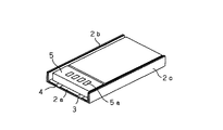
本発明の非水電解質電池(いわゆるリチウムイオン二次電池)は、例えば固体電解質電池、またはゲル状電解質電池であり、図1及び図2に示すように、正極活物質層と負極活物質層との間に固体電解質、またはゲル状電解質を配設してなる電池素子1をラミネートフィルムよりなる外装材2に収容し、周囲を熱溶着することにより封入されてなるものである。外形形状は、ほぼ矩形である。
【0017】
上記電池素子1には、電池素子1を構成する負極と電気的に接続される負極端子リード3、及び正極と電気的に接続される正極端子リード4が設けられており、これら負極端子リード3、正極端子リード4は、外装材2の外方へと引き出されている。
【0018】
これら負極端子リード3、正極端子リード4は、正負極のそれぞれの集電体に接合されており、その材質としては、正極端子リード4は高電位で溶解しないもの、例えばアルミニウム、チタン、あるいはこれらの合金等が挙げられる。負極端子リード3には、銅、ニッケル、またはこれらの合金を用いることができる。
【0019】
ここで、リチウムイオン二次電池は、電池本体と制御回路がいわゆる化粧ケースにパックされてはじめて最終製品としての電池になる。
【0020】
この際、限られたスペース内を有効利用してより多くの電池素子を投入し、より体積効率を上げることで高性能化することが望まれる。
【0021】
扁平型の電池をラミネートフィルムにパックした電池では、その封止部をどのように処理するかが、この体積効率を大きく左右する。特に同じ容量の電池であれば、いかに薄く仕上げるかが重要で、例えば厚さ3mmの電池において100μm厚くなることは体積効率が3%悪くなることを、厚さ0.5mmの電池において100μm厚くなることは体積効率が20%悪くなることを意味する。
【0022】
また、端子リードの取り出し方向としては、例えば特開平10−208710号公報に記載されるように、電池素子集電体の面を利用してラミネートフィルムの熱溶着部ではない部分から取り出す構造が示されているが、制御回路との接続を考えた場合、制御回路との接続配線が電池厚み方向に存在してしまうため、電池本体と制御回路が化粧ケースにパックされて最終製品の電池となった場合、却って体積効率の悪い電池になってしまう。
【0023】
そこで、図1及び図2に示すように、ラミネートフィルムの熱溶着部2aで負極端子リード3、正極端子リード4を挟持し、ここから取り出すようにする。
【0024】
そして、ここに生じる電池素子1の存在しないスペースに、制御回路5を搭載する。こうすることで、単に電池素子1と制御回路5が電気的に接続されるばかりか、制御回路5は外装材2の熱溶着部2a上に保持され、振動や衝撃に対して安定になる。
【0025】
このとき、外装材2として、電池素子1を収容しうる空間を予め例えば深絞り成形により形成したものを用いれば、制御回路5を搭載するスペースを有効に生み出して、より有効なスペース利用することが可能になる。
【0026】
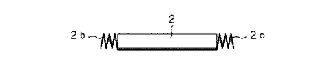
また、端子リードが取り出される方向以外の外装材2の熱溶着部の処理であるが、上記端子リードが取り出される熱溶着部2aと直交する2辺に対応する熱溶着部2b,2cを電池の厚み以下の幅となるように1回以上折り曲げ、これを電池側端部に折り畳んで、厚み方向の電池外寸が短くなるように考慮し、この折り畳み部、すなわち熱溶着部2b,2cで制御回路5を含めた電池が保護されるようにしている。
【0027】
このように熱溶着部2b,2cを電池側端部に折り畳み、厚み方向の電池外寸が短くなるようにすることで、体積効率が大幅に向上する。例えば、厚さ3.3mmの電池素子の場合に約5%、厚さ0.5mmの電池素子の場合に約25%もの体積効率の差が生じる。
【0028】
また、この折り畳まれた熱溶着部2b,2cは、外部からの衝撃に対して制御回路5を側面から保護する働きも有している。したがって、上記構成とすることで、電池の制御回路も含めた電池外寸での体積エネルギー密度が高く、優れた耐衝撃性を有する電池が得られる。
【0029】
以上が本発明を適用した非水電解質電池の基本的な構造であるが、その構造をより明確なものとするため、制御回路5を搭載するための手順について図3及び図4に示す。
【0030】
制御回路5を搭載するためには、先ず、図3に示すように熱溶着部2b,2cを電池側端部に折り畳む。そして、図4に示すように、負極端子リード3、正極端子リード4を熱溶着部2a上に折り返した後、この上に制御回路5を固定する。これにより、制御回路5と負極端子リード3、正極端子リード4とが電気的に接続され、上記構造の電池が得られる。
【0031】
上記構造の電池は、さらに化粧ケースのような容器に入れられ、最終製品とされるが、制御回路5の接続端子5aが容器に設けられた開口部を介して外部に臨むようにすれば、外部回路との接続が可能である。
【0032】
なお、上記熱溶着部2b,2cは、接着剤等で接着せずに、自身の有する塑性変形、例えば外装材2を構成する金属箔の塑性変形を利用して、折り畳み状態を維持するようにすることが望ましい。これにより、表面積が大きい状態に保たれ、放熱性が良く、サイクル特性の良い電池が得られる。
【0033】
また、上記熱溶着部2b,2cの幅が電池の厚みよりも大きい場合には、図5に示すように1度折り返してから折り畳むようにしてもよい。あるいは、電池の厚さが非常に薄い場合には、図6に示すように、熱溶着部2b,2cを蛇腹状に複数回折り返すようにしてもよい。
【0034】
上記熱溶着部2b,2cの折り畳みに際しては、ある程度の曲率を持って折り畳んだ方が好ましく、これにより、曲率がほとんど無い状態で折り畳んだものと比較して、例えば電池を落下させた場合に、ラミネートフィルムよりなる外装材2の損傷による密閉性の破壊を低減することができる。
【0035】
この場合、曲率半径が0.025mm以下では、実際に曲率を持たせた効果が現れ難い。曲率半径が1mm以上では体積効率のロスが大きい。好ましくは、0.05mm〜0.5mmである。曲率半径が0.05mm以上であれば、機械で折り曲げることが可能であり、線材を挟んで折り畳む等、各種の方法が簡便に利用できる。曲率半径0.5mm以上で折り畳むと、面方向からの衝撃を効果的に吸収するのが困難になる。
【0036】
ところで、上記熱溶着部2b,2cは、図7及び図8に示すように、底面側に折り畳むことも可能である。これも本発明の実施の形態の一つであるが、この場合には、若干体積効率が悪くなることは先に述べた通りである。
【0037】
かかる構成の場合、制御回路5を端子部封止エリアに収めるために、制御回路5の基板サイズはできるだけ小さくする必要がある。そこで、制御回路5に両面基板を使用し、基板の裏側にランドを設け電池との接続を図るようにすることが好ましい。
【0038】
また、電池の端子を直接制御回路5の基板に半田付けすることも可能であるが、電池の封止部である熱溶着部2aに熱が加わるとダメージが生ずるため、予め制御回路5の基板に端子を接続しておき、端子同士を抵抗溶接や超音波溶接等の熱影響の少ない手法によって接続することで、かかるダメージを抑えることができる。したがって、制御回路5の端子は、図9に示すように、別途形成した端子板6を制御回路5に貼り付け、これを負極端子リード3、正極端子リード4と重ね合わせるようにしても良いし、制御回路5自体を端子8が形成されたプリント配線基板7上に形成し、このプリント配線基板7を半分に折り曲げることで端子8が負極端子リード3、正極端子リード4と重ね合わせられるようにしても良い。
【0039】
この端子の処理であるが、そのままでは電池の外形が大きくなってしまうので折り曲げて処理したいところであるが、底面側に折り返すことにより熱溶着部2b,2cの段差を利用することができ、電池総厚を低く抑えることができる。
【0040】
一方、上記電池素子1であるが、例えば固体電解質電池、またはゲル状電解質電池を考えた場合、高分子固体電解質に使用する高分子材料としては、シリコンゲル、アクリルゲル、アクリロニトリルゲル、ポリフォスファゼン変成ポリマー、ポリエチレンオキサイド、ポリプロピレンオキサイド、及びこれらの複合ポリマーや架橋ポリマー、変成ポリマー等、もしくはフッ素系ポリマーとして、例えばポリ(ビニリデンフルオロライド)やポリ(ビニリデンフルオロライド-co-ヘキサフルオロプロピレン)、ポリ(ビニリデンフルオロライド-co-テトラフルオロエチレン)、ポリ(ビニリデンフルオロライド-co-トリフルオロエチレン)などおよびこれらの混合物が各種使用できるが、勿論、これらに限定されるものではない。
【0041】
正極活物質層または負極活物質層に積層されている固体電解質、またはゲル状電解質は、高分子化合物と電解質塩と溶媒、(ゲル電解質の場合は、さらに可塑剤)からなる溶液を正極活物質層または負極活物質層に含浸させ、溶媒を除去し固体化したものである。正極活物質層または負極活物質層に積層された固体電解質、またはゲル状電解質は、その一部が正極活物質層または負極活物質層に含浸されて固体化されている。架橋系の場合は、その後、光または熱で架橋して固体化される。
【0042】
ゲル状電解質は、リチウム塩を含む可塑剤と2重量%以上〜30重量%以下のマトリクス高分子からなる。このとき、エステル類、エーテル類、炭酸エステル類などを単独または可塑剤の一成分として用いることができる。
【0043】
ゲル状電解質を調整するにあたり、このような炭酸エステル類をゲル化するマトリクス高分子としては、ゲル状電解質を構成するのに使用されている種々の高分子が利用できるが、酸化還元安定性から、たとえばポリ(ビニリデンフルオロライド)やポリ(ビニリデンフルオロライド-co-ヘキサフルオロプロピレン)などのフッ素系高分子を用いることが望ましい。
【0044】
高分子固体電解質は、リチウム塩とそれを溶解する高分子化合物からなり、高分子化合物としては、ポリ(エチレンオキサイド)や同架橋体などのエーテル系高分子、ポリ(メタクリレート)エステル系、アクリレート系、ポリ(ビニリデンフルオロライド)やポリ(ビニリデンフルオロライド-co-ヘキサフルオロプロピレン)などのフッ素系高分子などを単独、または混合して用いることができるが、酸化還元安定性から、たとえばポリ(ビニリデンフルオロライド)やポリ(ビニリデンフルオロライド-co-ヘキサフルオロプロピレン)などのフッ素系高分子を用いることが望ましい。
【0045】
このようなゲル状電解質または高分子固体電解質に含有させるリチウム塩として通常の電池電解液に用いられるリチウム塩を使用することができ、リチウム化合物(塩)としては、例えば以下のものが挙げられるが、これらに限定されるものではない。
【0046】
たとえば、塩化リチウム臭化リチウム、ヨウ化リチウム、塩素酸リチウム、過塩素酸リチウム、臭素酸リチウム、ヨウ素酸リチウム、硝酸リチウム、テトラフルオロほう酸リチウム、ヘキサフルオロリン酸リチウム、酢酸リチウム、ビス(トリフルオロメタンスルフォニル)イミドリチウム、LiAsF6、LiCF3SO3、LiC(SO2CF3)3、LiAlCl4、LiSiF6等を挙げることができる。
【0047】
これらリチウム化合物は単独で用いても複数を混合して用いても良いが、これらの中でLiPF6、LiBF4が酸化安定性の点から望ましい。
【0048】
リチウム塩を溶解する濃度として、ゲル状電解質なら、可塑剤中に0.1〜3.0モルで実施できるが、好ましくは0.5から2.0モル/リットルで用いることができる。
【0049】
本発明の電池は、上記のようなゲル状電解質もしくは固体電解質を使用する以外は、従来のリチウムイオン電池と同様に構成することができる。
【0050】
すなわち、リチウムイオン電池を構成する場合の負極材料としては、リチウムをドープ、脱ドープできる材料を使用することができる。このような負極の構成材料、たとえば難黒鉛化炭素系材料や黒鉛系材料の炭素材料を使用することができる。より具体的には、熱分解炭素類、コークス類(ピッチコークス、ニードルコークス、石油コークス)、黒鉛類、ガラス状炭素類、有機高分子化合物焼成体(フェノール樹脂、フラン樹脂等を適当な温度で焼成し炭素化したもの)、炭素繊維、活性炭等の炭素材料を使用することができる。このほか、リチウムをドープ、脱ドープできる材料としては、ポリアセチレン、ポリピロール等の高分子やSnO2 等の酸化物を使用することもできる。このような材料から負極を形成するに際しては、公知の結着剤等を添加することができる。
【0051】
正極は、目的とする電池の種類に応じて、金属酸化物、金属硫化物または特定の高分子を正極活物質として用いて構成することができる。たとえばリチウムイオン電池を構成する場合、正極活物質としては、TiS2、MoS2、NbSe2,V2O5等のリチウムを含有しない金属硫化物あるいは酸化物や、LiMO2 (式中Mは一種以上の遷移金属を表し、xは電池の充放電状態によって異なり、通常0.05以上1.10以下である。)を主体とするリチウム複合酸化物等を使用することができる。このリチウム複合酸化物を構成する遷移金属Mとしては、Co,Ni,Mn等が好ましい。このようなリチウム複合酸化物の具体例としてはLiCoO2,LiNiO2,LiNiyCo1-yO2(式中、0<y<1である。)、LiMn2O4等を挙げることができる。これらリチウム複合酸化物は、高電圧を発生でき、エネルギー密度的に的に優れた正極活物質となる。正極には、これらの正極活物質の複数種を併せて使用してもよい。また、以上のような正極活物質を使用して正極を形成するに際して、公知の導電剤や結着剤等を添加することができる。
【0052】
上記電池素子1の構造としては、固体電解質を挟んで正極、負極を交互に積層した積み重ね型、正極及び負極を固体電解質を挟んで重ね合わせ、これを巻き取った巻き取り型、正極及び負極を固体電解質を挟んで重ね合わせ、これを交互に折りたたんだ折り畳み型等を挙げることができ、任意に選定することができる。
【0053】
本発明は、一次電池、二次電池のいずれにも適用可能であるが、特に非水電解液二次電池へ適用することで、大きな効果を得ることができる。
【0054】
【実施例】
次に、本発明を適用した具体的な実施例及び比較例について、実験結果に基づいて説明する。
【0055】
サンプル電池の作製方法、及び評価方法は下記の通りである。
【0056】
サンプル電池の作製
先ず、負極を次のように作製した。
【0057】
粉砕した黒鉛粉末90重量部と、結着剤としてポリ(ビニリデンフルオロライド-co-ヘキサフルオロプロピレン)10重量部とを混合して負極合剤を調製し、さらにこれをN-メチル−2−ピロリドンに分散させスラリー状とした。そして、このスラリーを負極集電体である厚さ10μmの帯状銅箔の片面に均一に塗布し、乾燥後、ロールプレス機で圧縮成形し、負極を作製した。
【0058】
一方、正極を次のように作製した。
【0059】
正極活物質(LiCoO2)を得るために、炭酸リチウムと炭酸コバルトを0.5モル対1モルの比率で混合し、空気中、900℃で5時間焼成した。次に、得られたLiCoO2 91重量部、導電剤として黒鉛6重量部、結着剤としてポリ(ビニリデンフルオロライド-co-ヘキサフルオロプロピレン)10重量部とを混合して正極合剤を調製し、さらにこれをN−メチル−2−ピロリドンに分散させスラリー状とした。そして、このスラリーを正極集電体である厚さ20μmの帯状アルミニウム箔の片面に均一に塗布し、乾燥した後、ロールプレス機で圧縮成形し、正極を作製した。
【0060】
さらに、ゲル状電解質を次のようにして得た。
【0061】
負極、正極上に炭酸エチレン(EC)42.5重量部、炭酸プロピレン(PC)42.5重量部、LiPF6 15重量部からなる可塑剤30重量部に、重量平均分子量Mw60万のポリ(ビニリデンフルオロライド-co-ヘキサフルオロプロピレン)10重量部、そして炭酸ジエチル60重量部を混合溶解させた溶液を均一に塗布し、含浸させ、常温で8時間放置し、炭酸ジメチルを気化、除去しゲル状電解質を得た。
【0062】
ゲル状電解質を塗布した負極、及び正極をゲル状電解質側をあわせ、圧着することで面積3.3cm×5.2cm、厚さ0.3mmで容量50mAhの平板型ゲル状電解質電池、及び面積3.3cm×5.2cm、厚さ3.3mmで容量550mAhの平板型ゲル状電解質電池を作製した。
【0063】
極板の活物質層が塗工されていない部分(正極はアルミ箔、負極は銅箔)上にアルミニウムからなる正極端子リード及びニッケルからなる負極端子リードを溶接した後、ラミネートフィルムからなる封入体に挿入し、200℃、10秒の条件でシール機によりシール幅5mmで熱融着し、試験電池とした。
【0064】
各サンプルの構成は以下の通りである。
【0065】
サンプル1:熱溶着部2b,2cを波状に電池側端部に折り畳んだ。その結果、3.3cm方向の寸法が3.4cmとなった。厚みは3.5mmである。
【0066】
サンプル2:熱溶着部2b,2cを内側に巻いて電池側端部に折り畳んだ。その結果、3.3cm方向の寸法が3.4cmとなった。厚みは3.5mmである。
【0067】
サンプル3:熱溶着部2b,2cを巻いて折り畳んだ。その結果、3.3cm方向の寸法が3.82cmとなった。厚みは0.5mmである。
【0068】
サンプル4:熱溶着部2b,2cを蛇腹状に折り畳んだ。その結果、3.3cm方向の寸法が3.72cmとなった。厚みは0.5mmである。
【0069】
サンプル5:電池の構成はサンプル1と同様である。ただし、熱溶着部2b,2cを折り畳む際に曲率を付けなかった。
【0070】
サンプル6:電池の構成はサンプル1と同様である。ただし、折り畳んだ熱溶着部2b,2cを接着した。
【0071】
サンプル7:熱溶着部2b,2cを底面側に折り畳んだ。その結果、3.3cm方向の寸法が3.32cmとなった。厚みは0.7mmである。
【0072】
サンプル8:熱溶着部2b,2cを底面側に折り畳んだ。その結果、3.3cm方向の寸法が3.32cmとなった。厚みは3.7mmである。
【0073】
サンプル9:外装材に深絞り加工を施していないものを用い、他はサンプル1と同様の構成とした。3.3cm方向の寸法は3.4cm、厚みは3. 5mmであるが、制御回路を含めて考えると、この部分が突出して いるために厚みが5mmとなる。
【0074】
サンプル10:熱溶着部2aに制御回路を搭載せず、制御回路が端子リードの外側に突出して取り付けられている。
【0075】
なお、各サンプルに用いた制御回路の外形寸法は、32mm×5mm×3mmである。
【0076】
これら各サンプルの構成上の特徴を表1にまとめて示す。
【0077】
【表1】

評価
各サンプルの評価項目は、次の通りである。
【0079】
1.各サンプルについて、理論容量の5時間率(1/5C)にて初充放電後、理論容量の2時間率(1/2C)にて充電し、放電したときの容量と平均放電電圧をもって、ラミネートフィルムにパックされて制御回路を搭載したものが外装する直方体体積で体積エネルギー密度を算出した。
【0080】
2.各サンプルについて、理論容量の2時間率放電(1/2C)において50℃環境下で500回の充放電サイクル試験を行い、放電容量の維持率を測定した。
【0081】
3.各サンプルについて、2mの高さから50回の落下試験を実施した後、70℃、相対湿度90%の恒温恒湿槽に入れ、720時間後にカールフィッシャー法による水分測定を行った。
【0082】
結果を表2に示す。
【0083】
【表2】
表2からも明らかなように、熱溶着部を曲率をもって電池側端部に折り畳んだサンプル1〜4は、良好な体積エネルギー密度を有し、耐衝撃性も良好で、水分の侵入も極めて少なく、良好なサイクル特性を示すことが確認された。
【0085】
これに対して、熱溶着部を曲率を付けないで折り畳んだサンプル5では、耐衝撃性が不十分で、ラミネートフィルムで形成されるコーナー部の損傷のせいか水分の侵入で有意差が確認された。
【0086】
熱溶着部を接着したサンプル6では、放熱特性がサイクル特性に与える影響が確認された。
【0087】
サンプル1、2とサンプル8との対比、及びサンプル3、4とサンプル7との対比から、電極端子リードがラミネートフィルムに挟持され熱溶着される部分以外の熱溶着部を電池の厚み以下の幅となるように折り曲げ電池側端部に折り畳むことによる体積エネルギー密度に与える効果が確認された。
【0088】
さらに、サンプル1、2とサンプル9、10との対比からは、電池を収容する空間が形成されたラミネートフィルムを用い、端子部に生じる空間に制御回路を搭載することによる効果が確認された。
【0089】
【発明の効果】
以上の説明からも明らかなように、本発明によれば、体積エネルギー密度が良好で、制御回路を含め電池全体に耐衝撃性が付与されており、また放熱特性が向上されていて充放電サイクル寿命が長く、生産性に優れた非水電解質電池を提供することが可能である。
【図面の簡単な説明】
【図1】本発明が適用された非水電解質電池の一構成例を示す概略斜視図である。
【図2】本発明が適用された非水電解質電池の一構成例を示す概略断面図である。
【図3】熱溶着部の折り畳み工程を示す概略斜視図である。
【図4】電極端子リードの折り返し工程を示す概略斜視図である。
【図5】熱溶着部の折り畳み状態の一例を示す概略斜視図である。
【図6】熱溶着部の折り畳み状態の他の例を示す概略斜視図である。
【図7】本発明が適用された非水電解質電池の他の例を示す概略斜視図である。
【図8】本発明が適用された非水電解質電池の他の例を示す概略正面図である。
【図9】制御回路における端子の形成例を示す分解斜視図である。
【符号の説明】
1 電池素子、2 外装材、2a,2b,2c 熱溶着部、3 負極端子リード、4 正極端子リード、5 制御回路[0001]
BACKGROUND OF THE INVENTION
The present invention relates to a non-aqueous electrolyte battery in which a battery element is housed in a packaging material made of a laminate film, and particularly relates to an improvement in volume energy density in a gel electrolyte battery, a solid electrolyte battery, and the like.
[0002]
[Prior art]
In recent years, many portable electronic devices such as a camera-integrated VTR, a mobile phone, and a portable computer have appeared, and their size and weight have been reduced. As portable power sources for these electronic devices, research and development of thin and foldable batteries are being actively promoted for batteries, particularly secondary batteries, and particularly non-aqueous electrolyte secondary batteries (so-called lithium ion batteries).
[0003]
Research into solid electrolytes as electrolytes for such freely shaped batteries is active, especially polymer electrolytes in which lithium salts are dissolved in gel electrolytes or polymers that are solid electrolytes containing plasticizers. Is attracting attention.
[0004]
On the other hand, in order to take advantage of such a thin and light battery, various types of batteries that are encapsulated by using a plastic film or a so-called laminate film in which a plastic film and a metal are bonded together have been studied.
[0005]
[Problems to be solved by the invention]
By the way, in the case of a secondary battery, for example, it is necessary to arrange a control circuit for controlling charging / discharging around the battery, and a structure that improves volumetric efficiency while mounting this charging / discharging control circuit is required. .
[0006]
Moreover, in the battery having the above structure, the entire battery including the control circuit has impact resistance, the efficiency when the volume energy density is defined by the outside dimension of the battery made of a laminate film, and the heat dissipation characteristics are improved. Therefore, it is required to study the battery characteristics from various aspects such as improving the charge / discharge cycle life, which is an item related to the performance in actual use of the battery.
[0007]
Therefore, the present invention has been proposed in view of such conventional circumstances, and an object thereof is to provide a non-aqueous electrolyte battery having a high volumetric efficiency while mounting a control circuit.
[0008]
Another object of the present invention is to provide a non-aqueous electrolyte battery that is excellent in impact resistance and heat dissipation characteristics and has a long charge / discharge cycle life, which is an item related to performance during actual use of the battery.
[0009]
Furthermore, an object of this invention is to provide the nonaqueous electrolyte battery excellent in productivity.
[0010]
[Means for Solving the Problems]
In order to achieve the above object, according to the present invention, a battery element is housed in a packaging material made of a laminate film, sealed by thermal welding, and electrode terminal leads connected to the respective electrodes constituting the battery element are heated. In the nonaqueous electrolyte battery sandwiched between the welded portions and exposed to the outside of the exterior material, the outer shape is rectangular, and among the four sides, the heat welded portion corresponding to one side from which the electrode terminal lead is drawn out The battery control circuit is mounted, and the heat-welded part corresponding to the other side is folded along the side surface of the exterior member, and the other side is perpendicular to the side from which the electrode terminal lead is drawn. And both ends of the heat-welded part on which the control circuit is mounted are formed by rising to constitute a space for accommodating the control circuit .
[0011]
By mounting a battery control circuit on the heat-welded portion of the exterior material, a space where there is no battery element within the battery dimensions is effectively used, and the volumetric efficiency is greatly improved.
[0012]
The above is the basic idea of the present invention. Furthermore, in the present invention, in order to increase the volume energy density at the outer dimensions of the battery including the battery control circuit and to obtain excellent impact resistance, the electrode terminals The battery is formed by bending a heat-welded portion other than the portion where the lead is sandwiched between the laminated films and heat-welded at least once so as to have a width equal to or less than the thickness of the battery (the shortest battery dimension is defined as the battery thickness). The entire battery including the control circuit is protected by the folded portion so that the outer dimension of the battery in the thickness direction is shortened as much as possible.
[0013]
Moreover, in order to improve the heat dissipation as a battery, the surface area is increased by folding the folded part folded at the battery side end without bonding.
[0014]
In order to improve impact resistance, the folding portion is further folded with a curvature when folded on the battery side end portion.
[0015]
DETAILED DESCRIPTION OF THE INVENTION
Hereinafter, the configuration of a nonaqueous electrolyte battery to which the present invention is applied will be described with reference to the drawings.
[0016]
The nonaqueous electrolyte battery (so-called lithium ion secondary battery) of the present invention is, for example, a solid electrolyte battery or a gel electrolyte battery, and as shown in FIGS. 1 and 2, a positive electrode active material layer, a negative electrode active material layer, A
[0017]
The
[0018]
The negative
[0019]
Here, the lithium ion secondary battery becomes a battery as a final product only after the battery body and the control circuit are packed in a so-called cosmetic case.
[0020]
At this time, it is desired to improve performance by effectively using the limited space and introducing more battery elements to increase volumetric efficiency.
[0021]
In a battery in which a flat battery is packed in a laminate film, the volume efficiency greatly depends on how the sealing portion is treated. In particular, if the batteries have the same capacity, it is important how to finish them thinly. For example, increasing the thickness by 100 μm in a battery having a thickness of 3 mm results in 3% deterioration in volume efficiency, and increasing by 100 μm in a battery having a thickness of 0.5 mm. This means that the volumetric efficiency is 20% worse.
[0022]
Further, as a terminal lead extraction direction, for example, as described in JP-A-10-208710, a structure in which the surface of the battery element current collector is used to extract from a portion other than the heat welded portion of the laminate film is shown. However, considering the connection with the control circuit, the connection wiring with the control circuit exists in the battery thickness direction, so the battery body and the control circuit are packed in a decorative case to become the final product battery. If this happens, the battery will have a poor volumetric efficiency.
[0023]
Therefore, as shown in FIG. 1 and FIG. 2, the negative
[0024]
And the
[0025]
At this time, if a space in which the
[0026]
In addition, in the processing of the heat-welded portion of the
[0027]
As described above, the volume efficiency is greatly improved by folding the heat-welded
[0028]
The folded
[0029]
The above is the basic structure of the non-aqueous electrolyte battery to which the present invention is applied. In order to make the structure clearer, the procedure for mounting the
[0030]
In order to mount the
[0031]
The battery having the above structure is further put into a container such as a decorative case to be a final product, but if the connection terminal 5a of the
[0032]
Note that the heat-welded
[0033]
Further, when the width of the heat welded
[0034]
When folding the heat-welded
[0035]
In this case, if the radius of curvature is 0.025 mm or less, the effect of actually giving the curvature is difficult to appear. When the curvature radius is 1 mm or more, the loss of volume efficiency is large. Preferably, it is 0.05 mm-0.5 mm. If the radius of curvature is 0.05 mm or more, it can be bent by a machine, and various methods such as folding with a wire sandwiched between them can be easily used. When folded with a curvature radius of 0.5 mm or more, it becomes difficult to effectively absorb the impact from the surface direction.
[0036]
By the way, as shown in FIG.7 and FIG.8, the said
[0037]
In the case of such a configuration, the substrate size of the
[0038]
Although it is possible to solder the battery terminals directly to the substrate of the
[0039]
This is the terminal treatment, but the outer shape of the battery becomes large as it is, so that it is desired to bend and treat, but by folding back to the bottom side, the steps of the heat welded
[0040]
On the other hand, when the
[0041]
For the solid electrolyte or gel electrolyte laminated on the positive electrode active material layer or the negative electrode active material layer, a solution comprising a polymer compound, an electrolyte salt, and a solvent (or a plasticizer in the case of a gel electrolyte) is used as the positive electrode active material. A layer or a negative electrode active material layer is impregnated, and the solvent is removed and solidified. Part of the solid electrolyte or the gel electrolyte laminated on the positive electrode active material layer or the negative electrode active material layer is impregnated into the positive electrode active material layer or the negative electrode active material layer to be solidified. In the case of a crosslinked system, it is then solidified by crosslinking with light or heat.
[0042]
The gel electrolyte is composed of a plasticizer containing a lithium salt and a matrix polymer of 2 wt% to 30 wt%. At this time, esters, ethers, carbonates and the like can be used alone or as one component of a plasticizer.
[0043]
In preparing the gel electrolyte, various polymers used to form the gel electrolyte can be used as the matrix polymer for gelling such carbonates. From the viewpoint of redox stability, For example, it is desirable to use a fluorine-based polymer such as poly (vinylidene fluoride) or poly (vinylidene fluoride-co-hexafluoropropylene).
[0044]
The polymer solid electrolyte is composed of a lithium salt and a polymer compound that dissolves the lithium salt. Examples of the polymer compound include ether polymers such as poly (ethylene oxide) and cross-linked polymers, poly (methacrylate) esters, and acrylates. Fluorine polymers such as poly (vinylidene fluoride) and poly (vinylidene fluoride-co-hexafluoropropylene) can be used singly or in combination. For example, poly (vinylidene) can be used because of redox stability. Fluoropolymers such as (fluoride) and poly (vinylidene fluoride-co-hexafluoropropylene) are preferably used.
[0045]
As a lithium salt to be contained in such a gel electrolyte or a polymer solid electrolyte, a lithium salt used in a normal battery electrolyte can be used. Examples of the lithium compound (salt) include the following. However, it is not limited to these.
[0046]
For example, lithium chloride lithium bromide, lithium iodide, lithium chlorate, lithium perchlorate, lithium bromate, lithium iodate, lithium nitrate, lithium tetrafluoroborate, lithium hexafluorophosphate, lithium acetate, bis (trifluoromethane Examples thereof include sulfonyl) imidolithium, LiAsF 6 , LiCF 3 SO 3 , LiC (SO 2 CF 3 ) 3 , LiAlCl 4 , and LiSiF 6 .
[0047]
These lithium compounds may be used alone or in combination, and among them, LiPF 6 and LiBF 4 are desirable from the viewpoint of oxidation stability.
[0048]
As a concentration for dissolving the lithium salt, a gel electrolyte can be used at 0.1 to 3.0 mol in the plasticizer, but preferably 0.5 to 2.0 mol / liter.
[0049]
The battery of the present invention can be configured in the same manner as a conventional lithium ion battery except that the gel electrolyte or solid electrolyte as described above is used.
[0050]
That is, as a negative electrode material for constituting a lithium ion battery, a material capable of doping and dedoping lithium can be used. A constituent material of such a negative electrode, for example, a non-graphitizable carbon material or a carbon material such as a graphite material can be used. More specifically, pyrolytic carbons, cokes (pitch coke, needle coke, petroleum coke), graphites, glassy carbons, organic polymer compound fired bodies (phenol resin, furan resin, etc.) at an appropriate temperature. Carbon materials such as those obtained by firing and carbonization), carbon fibers, activated carbon, and the like can be used. In addition, as a material capable of doping and dedoping lithium, a polymer such as polyacetylene or polypyrrole or an oxide such as SnO 2 can be used. In forming the negative electrode from such a material, a known binder or the like can be added.
[0051]
The positive electrode can be configured using a metal oxide, a metal sulfide, or a specific polymer as the positive electrode active material, depending on the type of the target battery. For example, in the case of constituting a lithium ion battery, the positive electrode active material may be a metal sulfide or oxide not containing lithium, such as TiS 2 , MoS 2 , NbSe 2 , V 2 O 5 , LiMO 2 (wherein M is one kind) The above transition metals are represented, and x varies depending on the charge / discharge state of the battery and is usually 0.05 or more and 1.10 or less. As the transition metal M constituting this lithium composite oxide, Co, Ni, Mn and the like are preferable. Specific examples of such a lithium composite oxide include LiCoO 2 , LiNiO 2 , LiNi y Co 1-y O 2 (where 0 <y <1), LiMn 2 O 4 and the like. . These lithium composite oxides can generate a high voltage and become a positive electrode active material excellent in energy density. A plurality of these positive electrode active materials may be used in combination for the positive electrode. Moreover, when forming a positive electrode using the positive electrode active material as described above, a known conductive agent, binder or the like can be added.
[0052]
The structure of the
[0053]
The present invention can be applied to both a primary battery and a secondary battery, but a significant effect can be obtained particularly when applied to a non-aqueous electrolyte secondary battery.
[0054]
【Example】
Next, specific examples and comparative examples to which the present invention is applied will be described based on experimental results.
[0055]
The production method and evaluation method of the sample battery are as follows.
[0056]
Production of sample battery First, a negative electrode was produced as follows.
[0057]
90 parts by weight of the pulverized graphite powder and 10 parts by weight of poly (vinylidene fluoride-co-hexafluoropropylene) as a binder are mixed to prepare a negative electrode mixture, which is further mixed with N-methyl-2-pyrrolidone. To form a slurry. And this slurry was uniformly apply | coated to the single side | surface of a 10-micrometer-thick strip | belt-shaped copper foil which is a negative electrode electrical power collector, after drying, it compression-molded with the roll press machine, and produced the negative electrode.
[0058]
On the other hand, the positive electrode was produced as follows.
[0059]
In order to obtain a positive electrode active material (LiCoO 2 ), lithium carbonate and cobalt carbonate were mixed at a ratio of 0.5 mol to 1 mol and fired at 900 ° C. for 5 hours in the air. Next, 91 parts by weight of LiCoO 2 obtained, 6 parts by weight of graphite as a conductive agent, and 10 parts by weight of poly (vinylidene fluoride-co-hexafluoropropylene) as a binder are mixed to prepare a positive electrode mixture. Further, this was dispersed in N-methyl-2-pyrrolidone to form a slurry. And this slurry was uniformly apply | coated to the single side | surface of a 20-micrometer-thick strip | belt-shaped aluminum foil which is a positive electrode electrical power collector, after drying, it compression-molded with the roll press machine, and produced the positive electrode.
[0060]
Further, a gel electrolyte was obtained as follows.
[0061]
A poly (vinylidene) having a weight average molecular weight Mw of 600,000 was added to 30 parts by weight of a plasticizer comprising 42.5 parts by weight of ethylene carbonate (EC), 42.5 parts by weight of propylene carbonate (PC) and 15 parts by weight of LiPF 6 on the negative electrode and the positive electrode. Fluoride-co-hexafluoropropylene) 10 parts by weight and 60 parts by weight of diethyl carbonate mixed and dissolved uniformly, impregnated and left at room temperature for 8 hours to vaporize and remove dimethyl carbonate to form a gel An electrolyte was obtained.
[0062]
A negative electrode to which a gel electrolyte is applied, and a positive electrode are bonded to the gel electrolyte side, and are pressed together to form a flat gel electrolyte battery having an area of 3.3 cm × 5.2 cm, a thickness of 0.3 mm and a capacity of 50 mAh, and an area of 3 A plate type gel electrolyte battery having a capacity of 550 mAh and a thickness of 3.3 cm × 5.2 cm and a thickness of 3.3 mm was manufactured.
[0063]
Enclosed body made of laminate film after welding positive electrode terminal lead made of aluminum and negative electrode terminal lead made of nickel on the portion of the electrode plate where the active material layer is not coated (aluminum foil for the positive electrode and copper foil for the negative electrode) And heat-sealed with a sealer at a seal width of 5 mm under the conditions of 200 ° C. and 10 seconds to obtain a test battery.
[0064]
The configuration of each sample is as follows.
[0065]
Sample 1: The heat-welded
[0066]
Sample 2: The heat-welded
[0067]
Sample 3: The
[0068]
Sample 4: The heat-welded
[0069]
Sample 5: The configuration of the battery is the same as that of
[0070]
Sample 6: The configuration of the battery is the same as that of
[0071]
Sample 7: The heat-welded
[0072]
Sample 8: The heat-welded
[0073]
Sample 9: The exterior material was not subjected to deep drawing, and the other configuration was the same as that of
[0074]
Sample 10: The control circuit is not mounted on the heat-welded portion 2a, and the control circuit is attached to the outside of the terminal lead.
[0075]
The external dimensions of the control circuit used for each sample are 32 mm × 5 mm × 3 mm.
[0076]
The structural characteristics of each sample are summarized in Table 1.
[0077]
[Table 1]
Evaluation The evaluation items of each sample are as follows.
[0079]
1. Each sample was initially charged / discharged at a theoretical capacity of 5 hours (1 / 5C), charged at a theoretical capacity of 2 hours (1 / 2C), and then laminated with the capacity and average discharge voltage when discharged. The volume energy density was calculated from the volume of a rectangular parallelepiped covered by a film packed with a control circuit.
[0080]
2. Each sample was subjected to 500 charge / discharge cycle tests under a 2-hour rate discharge (1/2 C) of the theoretical capacity in a 50 ° C. environment, and the discharge capacity retention rate was measured.
[0081]
3. Each sample was subjected to a drop test 50 times from a height of 2 m, then placed in a constant temperature and humidity chamber at 70 ° C. and 90% relative humidity, and after 720 hours, moisture measurement was performed by the Karl Fischer method.
[0082]
The results are shown in Table 2.
[0083]
[Table 2]
As is apparent from Table 2,
[0085]
On the other hand,
[0086]
In
[0087]
From the comparison between
[0088]
Furthermore, the comparison between
[0089]
【The invention's effect】
As is clear from the above description, according to the present invention, the volume energy density is good, the impact resistance is imparted to the entire battery including the control circuit, and the heat dissipation characteristics are improved, so that the charge / discharge cycle is achieved. It is possible to provide a nonaqueous electrolyte battery having a long life and excellent productivity.
[Brief description of the drawings]
FIG. 1 is a schematic perspective view showing a configuration example of a nonaqueous electrolyte battery to which the present invention is applied.
FIG. 2 is a schematic cross-sectional view showing a configuration example of a nonaqueous electrolyte battery to which the present invention is applied.
FIG. 3 is a schematic perspective view showing a folding process of a heat welding part.
FIG. 4 is a schematic perspective view showing an electrode terminal lead folding step.
FIG. 5 is a schematic perspective view showing an example of a folded state of a heat welding part.
FIG. 6 is a schematic perspective view showing another example of a folded state of a heat welding part.
FIG. 7 is a schematic perspective view showing another example of a nonaqueous electrolyte battery to which the present invention is applied.
FIG. 8 is a schematic front view showing another example of a nonaqueous electrolyte battery to which the present invention is applied.
FIG. 9 is an exploded perspective view showing an example of forming terminals in a control circuit.
[Explanation of symbols]
DESCRIPTION OF
Claims (14)
外形形状が矩形状であり、その4辺のうち上記電極端子リードが引き出される1辺に対応する熱溶着部に電池の制御回路が搭載されており、
他の辺に対応する熱溶着部が、外装材の側面に沿って折り畳まれており、
この他の辺が、上記電極端子リードが引き出される辺と直交する2辺であり、
上記折り畳みにより上記制御回路が搭載される熱溶着部の両端部分が立ち上がり形成され、上記制御回路を収容する空間を構成していることを特徴とする非水電解質電池。The battery element is housed in a packaging material made of a laminate film and sealed by thermal welding, and electrode terminal leads that are electrically connected to the respective electrodes constituting the battery element are sandwiched between thermal welding parts and exposed to the outside of the packaging material. In the nonaqueous electrolyte battery formed,
The outer shape is a rectangular shape, and a battery control circuit is mounted on the heat-welded portion corresponding to one of the four sides from which the electrode terminal lead is drawn,
The heat-welded part corresponding to the other side is folded along the side of the exterior material,
The other side is two sides orthogonal to the side from which the electrode terminal lead is drawn,
A non-aqueous electrolyte battery characterized in that both ends of a heat-welded part on which the control circuit is mounted are formed by folding so as to form a space for accommodating the control circuit .
Priority Applications (7)
| Application Number | Priority Date | Filing Date | Title |
|---|---|---|---|
| JP32851298A JP3899499B2 (en) | 1998-11-18 | 1998-11-18 | Non-aqueous electrolyte battery |
| TW088119704A TW444420B (en) | 1998-11-18 | 1999-11-11 | Nonaqueous electrolyte battery |
| DE69923148T DE69923148T2 (en) | 1998-11-18 | 1999-11-15 | Battery with non-aqueous electrolyte |
| EP99122700A EP1003233B1 (en) | 1998-11-18 | 1999-11-15 | Nonaqueous electrolyte battery |
| US09/440,537 US6368744B1 (en) | 1998-11-18 | 1999-11-16 | Nonaqueous electrolyte battery having a casing constituted by a laminate film |
| KR1019990051002A KR100648550B1 (en) | 1998-11-18 | 1999-11-17 | Nonaqueous electrolyte battery |
| CNB991273486A CN1147958C (en) | 1998-11-18 | 1999-11-18 | Non-water electrolyte battery |
Applications Claiming Priority (1)
| Application Number | Priority Date | Filing Date | Title |
|---|---|---|---|
| JP32851298A JP3899499B2 (en) | 1998-11-18 | 1998-11-18 | Non-aqueous electrolyte battery |
Publications (3)
| Publication Number | Publication Date |
|---|---|
| JP2000156208A JP2000156208A (en) | 2000-06-06 |
| JP2000156208A5 JP2000156208A5 (en) | 2005-06-16 |
| JP3899499B2 true JP3899499B2 (en) | 2007-03-28 |
Family
ID=18211117
Family Applications (1)
| Application Number | Title | Priority Date | Filing Date |
|---|---|---|---|
| JP32851298A Expired - Lifetime JP3899499B2 (en) | 1998-11-18 | 1998-11-18 | Non-aqueous electrolyte battery |
Country Status (7)
| Country | Link |
|---|---|
| US (1) | US6368744B1 (en) |
| EP (1) | EP1003233B1 (en) |
| JP (1) | JP3899499B2 (en) |
| KR (1) | KR100648550B1 (en) |
| CN (1) | CN1147958C (en) |
| DE (1) | DE69923148T2 (en) |
| TW (1) | TW444420B (en) |
Cited By (1)
| Publication number | Priority date | Publication date | Assignee | Title |
|---|---|---|---|---|
| US10490862B2 (en) | 2016-10-05 | 2019-11-26 | Samsung Sdi Co., Ltd. | Secondary battery with flexible circuit portion |
Families Citing this family (50)
| Publication number | Priority date | Publication date | Assignee | Title |
|---|---|---|---|---|
| JP4831269B2 (en) | 2000-03-17 | 2011-12-07 | ソニー株式会社 | Battery manufacturing method |
| DE20005816U1 (en) * | 2000-03-29 | 2000-07-13 | VARTA Gerätebatterie GmbH, 30419 Hannover | Electric accumulator with electronic safety protection circuit |
| GB0015325D0 (en) * | 2000-06-22 | 2000-08-16 | Danionics As | Electrochemical cells |
| JP4686823B2 (en) * | 2000-07-10 | 2011-05-25 | 株式会社Gsユアサ | Sealed battery |
| JP4793517B2 (en) * | 2000-07-10 | 2011-10-12 | 株式会社Gsユアサ | Sealed battery |
| JP2002270235A (en) * | 2001-03-07 | 2002-09-20 | Nisshinbo Ind Inc | Pregel component for polymer gel electrolyte and dehidrating method of the same, secondary cell and electric double layer capacitor |
| TW548860B (en) | 2001-06-20 | 2003-08-21 | Semiconductor Energy Lab | Light emitting device and method of manufacturing the same |
| JP2003142043A (en) | 2001-07-09 | 2003-05-16 | Hitachi Maxell Ltd | Battery |
| KR100958647B1 (en) | 2002-12-18 | 2010-05-20 | 삼성에스디아이 주식회사 | Pouch type secondary battery |
| US7348762B2 (en) | 2003-05-01 | 2008-03-25 | Sony Corporation | Battery pack and method for producing battery pack |
| KR100553200B1 (en) * | 2003-06-19 | 2006-02-22 | 삼성에스디아이 주식회사 | Battery pack |
| EP1686636A4 (en) | 2003-10-07 | 2009-04-22 | Nec Corp | Film-clad battery and method of producing film-clad battery |
| KR100553753B1 (en) * | 2003-10-16 | 2006-02-20 | 삼성에스디아이 주식회사 | Pouch type secondary battery |
| KR100561284B1 (en) * | 2003-12-26 | 2006-03-15 | 삼성에스디아이 주식회사 | Pouch type lithium secondary battery |
| CN2772044Y (en) * | 2004-11-18 | 2006-04-12 | 比亚迪股份有限公司 | Lithium ion secondary cell |
| KR100686815B1 (en) * | 2005-04-26 | 2007-02-26 | 삼성에스디아이 주식회사 | Polymer battery pack and manufacturing method the same |
| US20070044299A1 (en) * | 2005-08-30 | 2007-03-01 | Cheng-Hsin Chen | Method of fabricating rechargeable batteries |
| KR100760752B1 (en) * | 2005-12-23 | 2007-09-21 | 삼성에스디아이 주식회사 | Lithium polymer battery and the fabrication method thereof |
| KR100763931B1 (en) * | 2006-06-27 | 2007-10-05 | (주)비피에스 | Method of making battery using as case with shrinkage tube |
| JP4165586B2 (en) | 2006-08-02 | 2008-10-15 | ソニー株式会社 | Battery pack |
| KR100913836B1 (en) * | 2006-09-18 | 2009-08-26 | 주식회사 엘지화학 | Pouch-typed Secondary Battery with Improved Safety |
| JP4992921B2 (en) | 2009-02-19 | 2012-08-08 | ソニー株式会社 | Non-aqueous electrolyte secondary battery |
| WO2012047316A1 (en) * | 2010-05-21 | 2012-04-12 | Ada Technologies, Inc. | High performance carbon nano-tube composites for electrochemical energy storage devices |
| JP5035397B2 (en) | 2010-07-28 | 2012-09-26 | Tdk株式会社 | Electrochemical devices |
| JP5652976B2 (en) * | 2011-04-27 | 2015-01-14 | 日立マクセル株式会社 | Battery unit |
| KR20130016035A (en) | 2011-08-04 | 2013-02-14 | 주식회사 엘지화학 | Secondary battery pack of novel structure |
| KR20130016034A (en) * | 2011-08-04 | 2013-02-14 | 주식회사 엘지화학 | Secondary battery pack with improved safety |
| KR20130018097A (en) * | 2011-08-12 | 2013-02-20 | 주식회사 엘지화학 | Secondary battery pack of novel structure |
| US9343716B2 (en) | 2011-12-29 | 2016-05-17 | Apple Inc. | Flexible battery pack |
| TWI484881B (en) * | 2011-12-30 | 2015-05-11 | Uer Technology Corp | Welding structure and welding method for connecting lithium battery to electric circuit board |
| WO2013105231A1 (en) | 2012-01-11 | 2013-07-18 | 日立マクセル株式会社 | Battery unit |
| US9812680B2 (en) | 2012-08-30 | 2017-11-07 | Apple Inc. | Low Z-fold battery seal |
| US20140147703A1 (en) * | 2012-11-28 | 2014-05-29 | Apple Inc. | Battery safety circuit and tab placement and orientation |
| KR20140145787A (en) * | 2013-06-14 | 2014-12-24 | 삼성에스디아이 주식회사 | Rechargeable battery pack |
| US9799933B2 (en) * | 2013-08-28 | 2017-10-24 | Robert Bosch Gmbh | Solid state battery with integrated rate booster |
| KR101619926B1 (en) * | 2013-09-27 | 2016-05-12 | 주식회사 엘지화학 | Battery Pack Having PCM Case |
| US9593969B2 (en) | 2013-12-27 | 2017-03-14 | Apple Inc. | Concealed electrical connectors |
| US9479007B1 (en) | 2014-02-21 | 2016-10-25 | Apple Inc. | Induction charging system |
| US20150255776A1 (en) | 2014-03-06 | 2015-09-10 | Apple Inc. | Battery Pack System |
| US9455582B2 (en) | 2014-03-07 | 2016-09-27 | Apple Inc. | Electronic device and charging device for electronic device |
| US9917335B2 (en) | 2014-08-28 | 2018-03-13 | Apple Inc. | Methods for determining and controlling battery expansion |
| KR102290162B1 (en) * | 2015-01-19 | 2021-08-17 | 주식회사 아모그린텍 | Flexible battery and supplementary battery including the same |
| US10637017B2 (en) | 2016-09-23 | 2020-04-28 | Apple Inc. | Flexible battery structure |
| JP6762194B2 (en) * | 2016-10-11 | 2020-09-30 | 株式会社やまびこ | Backpack type power supply system |
| WO2018100846A1 (en) * | 2016-11-29 | 2018-06-07 | 株式会社村田製作所 | Secondary battery and device |
| WO2018100842A1 (en) * | 2016-11-29 | 2018-06-07 | 株式会社村田製作所 | Secondary battery |
| WO2018123330A1 (en) * | 2016-12-29 | 2018-07-05 | 株式会社村田製作所 | Negative electrode active material and method for manufacturing same, negative electrode, battery, battery pack, electronic device, electric vehicle, power storage device, and power system |
| CN111886712B (en) * | 2018-03-28 | 2023-06-23 | 本田技研工业株式会社 | Solid battery module |
| JP7224903B2 (en) * | 2018-12-26 | 2023-02-20 | 株式会社東芝 | BATTERY, BATTERY ASSEMBLY AND BATTERY MODULE |
| JP7194292B2 (en) | 2019-04-17 | 2022-12-21 | アップル インコーポレイテッド | radio localizable tag |
Family Cites Families (12)
| Publication number | Priority date | Publication date | Assignee | Title |
|---|---|---|---|---|
| CA2011720C (en) * | 1989-03-30 | 1999-11-30 | Robert A. Austin | Battery in a vacuum sealed enveloping material and a process for making the same |
| EP0644642A3 (en) * | 1993-07-30 | 1995-05-24 | Texas Instruments Inc | Improvements in or relating to power sources. |
| US5436089A (en) * | 1993-08-31 | 1995-07-25 | Vst Power Systems, Inc. | Portable battery pack apparatus and method of fabrication thereof |
| JP3344054B2 (en) * | 1993-12-29 | 2002-11-11 | ソニー株式会社 | Non-aqueous electrolyte secondary battery |
| JP3485655B2 (en) * | 1994-12-14 | 2004-01-13 | 株式会社ルネサステクノロジ | Composite MOSFET |
| JPH09139235A (en) * | 1995-11-16 | 1997-05-27 | Japan Storage Battery Co Ltd | Battery device |
| JPH10294097A (en) * | 1997-02-24 | 1998-11-04 | Mitsubishi Electric Corp | Thin type cell |
| DE69805683T2 (en) * | 1997-02-18 | 2003-02-06 | Koninklijke Philips Electronics N.V., Eindhoven | Thin-film accumulator device consisting of an electrochemical cell and electrical contact means |
| JPH10241736A (en) * | 1997-02-26 | 1998-09-11 | Rohm Co Ltd | Battery structure |
| US5895731A (en) * | 1997-05-15 | 1999-04-20 | Nelson E. Smith | Thin-film lithium battery and process |
| ES2263189T3 (en) * | 1997-11-05 | 2006-12-01 | Philips Consumer Communications France | BATTERY UNIT AND PORTABLE DEVICE POWERED BY BATTERY THAT INCLUDES SUCH BATTERY UNIT. |
| KR100863564B1 (en) * | 2008-03-26 | 2008-10-15 | 주식회사 텔론텍 | A arm device |
-
1998
- 1998-11-18 JP JP32851298A patent/JP3899499B2/en not_active Expired - Lifetime
-
1999
- 1999-11-11 TW TW088119704A patent/TW444420B/en not_active IP Right Cessation
- 1999-11-15 DE DE69923148T patent/DE69923148T2/en not_active Expired - Lifetime
- 1999-11-15 EP EP99122700A patent/EP1003233B1/en not_active Expired - Lifetime
- 1999-11-16 US US09/440,537 patent/US6368744B1/en not_active Expired - Lifetime
- 1999-11-17 KR KR1019990051002A patent/KR100648550B1/en active IP Right Grant
- 1999-11-18 CN CNB991273486A patent/CN1147958C/en not_active Expired - Lifetime
Cited By (1)
| Publication number | Priority date | Publication date | Assignee | Title |
|---|---|---|---|---|
| US10490862B2 (en) | 2016-10-05 | 2019-11-26 | Samsung Sdi Co., Ltd. | Secondary battery with flexible circuit portion |
Also Published As
| Publication number | Publication date |
|---|---|
| CN1259772A (en) | 2000-07-12 |
| EP1003233B1 (en) | 2005-01-12 |
| DE69923148D1 (en) | 2005-02-17 |
| TW444420B (en) | 2001-07-01 |
| CN1147958C (en) | 2004-04-28 |
| EP1003233A1 (en) | 2000-05-24 |
| US6368744B1 (en) | 2002-04-09 |
| KR100648550B1 (en) | 2006-11-24 |
| JP2000156208A (en) | 2000-06-06 |
| DE69923148T2 (en) | 2005-12-22 |
| KR20000047663A (en) | 2000-07-25 |
Similar Documents
| Publication | Publication Date | Title |
|---|---|---|
| JP3899499B2 (en) | Non-aqueous electrolyte battery | |
| JP4154633B2 (en) | Non-aqueous electrolyte battery | |
| US7563535B2 (en) | Battery pack with insulating film sheath material and method of producing the same | |
| JP4126711B2 (en) | Non-aqueous electrolyte battery | |
| KR100742109B1 (en) | Nonaqueous-electrolyte secondary battery and method of manufacturing the same | |
| JP4193267B2 (en) | Solid electrolyte battery | |
| US7297441B2 (en) | Nonaqueous-electrolyte secondary battery | |
| JP2000138040A (en) | Nonaqueous electrolyte battery | |
| KR100767196B1 (en) | Solid electrolyte cell | |
| EP2461391B1 (en) | Battery | |
| JP2003007345A (en) | Lithium secondary battery | |
| JP4269554B2 (en) | Lithium ion polymer battery and manufacturing method thereof | |
| JP4887634B2 (en) | Battery and its sealing method | |
| JP4735556B2 (en) | Method for producing solid electrolyte battery | |
| JP4449214B2 (en) | Non-aqueous electrolyte battery | |
| JP4782266B2 (en) | Non-aqueous electrolyte battery | |
| JP2001176501A (en) | Method of manufacturing non-aqueous electrolytic battery | |
| JP2001167798A (en) | Solid electrolyte cell | |
| JPH11121043A (en) | Manufacture of polymer secondary battery | |
| JP4590687B2 (en) | Non-aqueous electrolyte battery | |
| KR200242801Y1 (en) | Nonaqueous electrolyte battery | |
| JP2001229883A (en) | Power source device | |
| KR200242800Y1 (en) | Non-aqueous electrolyte cell | |
| JP2001176552A (en) | Non-aqueous electrolyte battery | |
| JP2002328755A (en) | Information recorder |
Legal Events
| Date | Code | Title | Description |
|---|---|---|---|
| A521 | Request for written amendment filed |
Free format text: JAPANESE INTERMEDIATE CODE: A523 Effective date: 20040924 |
|
| A621 | Written request for application examination |
Free format text: JAPANESE INTERMEDIATE CODE: A621 Effective date: 20040924 |
|
| A977 | Report on retrieval |
Free format text: JAPANESE INTERMEDIATE CODE: A971007 Effective date: 20060224 |
|
| A131 | Notification of reasons for refusal |
Free format text: JAPANESE INTERMEDIATE CODE: A131 Effective date: 20060411 |
|
| RD02 | Notification of acceptance of power of attorney |
Free format text: JAPANESE INTERMEDIATE CODE: A7422 Effective date: 20060413 |
|
| RD04 | Notification of resignation of power of attorney |
Free format text: JAPANESE INTERMEDIATE CODE: A7424 Effective date: 20060512 |
|
| A521 | Request for written amendment filed |
Free format text: JAPANESE INTERMEDIATE CODE: A523 Effective date: 20060612 |
|
| A131 | Notification of reasons for refusal |
Free format text: JAPANESE INTERMEDIATE CODE: A131 Effective date: 20060914 |
|
| A521 | Request for written amendment filed |
Free format text: JAPANESE INTERMEDIATE CODE: A523 Effective date: 20061110 |
|
| TRDD | Decision of grant or rejection written | ||
| A01 | Written decision to grant a patent or to grant a registration (utility model) |
Free format text: JAPANESE INTERMEDIATE CODE: A01 Effective date: 20061204 |
|
| A61 | First payment of annual fees (during grant procedure) |
Free format text: JAPANESE INTERMEDIATE CODE: A61 Effective date: 20061217 |
|
| FPAY | Renewal fee payment (event date is renewal date of database) |
Free format text: PAYMENT UNTIL: 20100112 Year of fee payment: 3 |
|
| FPAY | Renewal fee payment (event date is renewal date of database) |
Free format text: PAYMENT UNTIL: 20110112 Year of fee payment: 4 |
|
| FPAY | Renewal fee payment (event date is renewal date of database) |
Free format text: PAYMENT UNTIL: 20120112 Year of fee payment: 5 |
|
| FPAY | Renewal fee payment (event date is renewal date of database) |
Free format text: PAYMENT UNTIL: 20130112 Year of fee payment: 6 |
|
| R250 | Receipt of annual fees |
Free format text: JAPANESE INTERMEDIATE CODE: R250 |
|
| R250 | Receipt of annual fees |
Free format text: JAPANESE INTERMEDIATE CODE: R250 |
|
| R250 | Receipt of annual fees |
Free format text: JAPANESE INTERMEDIATE CODE: R250 |
|
| R250 | Receipt of annual fees |
Free format text: JAPANESE INTERMEDIATE CODE: R250 |
|
| S111 | Request for change of ownership or part of ownership |
Free format text: JAPANESE INTERMEDIATE CODE: R313111 Free format text: JAPANESE INTERMEDIATE CODE: R313113 |
|
| S531 | Written request for registration of change of domicile |
Free format text: JAPANESE INTERMEDIATE CODE: R313531 |
|
| R250 | Receipt of annual fees |
Free format text: JAPANESE INTERMEDIATE CODE: R250 |
|
| R360 | Written notification for declining of transfer of rights |
Free format text: JAPANESE INTERMEDIATE CODE: R360 |
|
| R350 | Written notification of registration of transfer |
Free format text: JAPANESE INTERMEDIATE CODE: R350 |
|
| R360 | Written notification for declining of transfer of rights |
Free format text: JAPANESE INTERMEDIATE CODE: R360 |
|
| R371 | Transfer withdrawn |
Free format text: JAPANESE INTERMEDIATE CODE: R371 |
|
| S111 | Request for change of ownership or part of ownership |
Free format text: JAPANESE INTERMEDIATE CODE: R313113 |
|
| R360 | Written notification for declining of transfer of rights |
Free format text: JAPANESE INTERMEDIATE CODE: R360 |
|
| R360 | Written notification for declining of transfer of rights |
Free format text: JAPANESE INTERMEDIATE CODE: R360 |
|
| R371 | Transfer withdrawn |
Free format text: JAPANESE INTERMEDIATE CODE: R371 |
|
| S111 | Request for change of ownership or part of ownership |
Free format text: JAPANESE INTERMEDIATE CODE: R313113 |
|
| R350 | Written notification of registration of transfer |
Free format text: JAPANESE INTERMEDIATE CODE: R350 |
|
| EXPY | Cancellation because of completion of term |