JP4780752B2 - Cutting device - Google Patents
Cutting device Download PDFInfo
- Publication number
- JP4780752B2 JP4780752B2 JP2004380812A JP2004380812A JP4780752B2 JP 4780752 B2 JP4780752 B2 JP 4780752B2 JP 2004380812 A JP2004380812 A JP 2004380812A JP 2004380812 A JP2004380812 A JP 2004380812A JP 4780752 B2 JP4780752 B2 JP 4780752B2
- Authority
- JP
- Japan
- Prior art keywords
- workpiece
- cutting
- work
- cutting blade
- stripper
- Prior art date
- Legal status (The legal status is an assumption and is not a legal conclusion. Google has not performed a legal analysis and makes no representation as to the accuracy of the status listed.)
- Expired - Fee Related
Links
Images


Classifications
-
- B—PERFORMING OPERATIONS; TRANSPORTING
- B23—MACHINE TOOLS; METAL-WORKING NOT OTHERWISE PROVIDED FOR
- B23D—PLANING; SLOTTING; SHEARING; BROACHING; SAWING; FILING; SCRAPING; LIKE OPERATIONS FOR WORKING METAL BY REMOVING MATERIAL, NOT OTHERWISE PROVIDED FOR
- B23D15/00—Shearing machines or shearing devices cutting by blades which move parallel to themselves
- B23D15/12—Shearing machines or shearing devices cutting by blades which move parallel to themselves characterised by drives or gearings therefor
-
- B—PERFORMING OPERATIONS; TRANSPORTING
- B23—MACHINE TOOLS; METAL-WORKING NOT OTHERWISE PROVIDED FOR
- B23D—PLANING; SLOTTING; SHEARING; BROACHING; SAWING; FILING; SCRAPING; LIKE OPERATIONS FOR WORKING METAL BY REMOVING MATERIAL, NOT OTHERWISE PROVIDED FOR
- B23D15/00—Shearing machines or shearing devices cutting by blades which move parallel to themselves
- B23D15/02—Shearing machines or shearing devices cutting by blades which move parallel to themselves having both upper and lower moving blades
-
- B—PERFORMING OPERATIONS; TRANSPORTING
- B23—MACHINE TOOLS; METAL-WORKING NOT OTHERWISE PROVIDED FOR
- B23D—PLANING; SLOTTING; SHEARING; BROACHING; SAWING; FILING; SCRAPING; LIKE OPERATIONS FOR WORKING METAL BY REMOVING MATERIAL, NOT OTHERWISE PROVIDED FOR
- B23D33/00—Accessories for shearing machines or shearing devices
- B23D33/08—Press-pads; Counter-bases; Hold-down devices
Landscapes
- Engineering & Computer Science (AREA)
- Mechanical Engineering (AREA)
- Details Of Cutting Devices (AREA)
- Jigs For Machine Tools (AREA)
- Nonmetal Cutting Devices (AREA)
- Processing Of Stones Or Stones Resemblance Materials (AREA)
- Shearing Machines (AREA)
Description
本発明はワーク(例えば配線基板、パッケージ基板、コンデンサ、インダクタ、抵抗体、磁性体等の積層基板、積層型電子部品)の切断加工装置に関するものである。 The present invention relates to a cutting device of a work (e.g. wiring board, a package substrate, a capacitor, an inductor, resistor, layered substrate, the multilayer electronic component such as the magnetic material).
従来、切断加工装置にはバキューム式のインデックステーブルでワークを吸着して、90度回動させる度に上切断刃を具備する切断加工機で所定ピッチ宛そのワークをカットして、ワークをチップ状に成形していた(例えば特許文献1)。
この特許文献1では、ワークが可撓性を有して取扱いが面倒なため、金属製の矩形枠状のワークホルダにそのワークをテープ等の沿え貼りで仮止めし、それによりワークの切断加工装置へのローダー等へのセッティングを容易にしている。特許文献2等がその公知例である。
また、前記特許文献1、2に示すようなフルカットではないが、上下のカッターホルダに弾機を介して上下のストリッパを支持し、ワークホルダで支持されるワークをその上下の切断刃でワークを所定深さ分担して切り込み、焼成後切断砥石で残置される繋ぎ部を分断するハーフカット用の切断加工装置もある(例えば特許文献3)。
Conventionally, a workpiece is picked up by a vacuum type index table and cut into a predetermined pitch by a cutting machine equipped with an upper cutting blade every time the workpiece is rotated 90 degrees, and the workpiece is chipped. (For example, Patent Document 1).
In this
Moreover, although it is not a full cut as shown in the said
ところで、一般的にワークは矩形枠状のワークホルダ上面に周縁が載置された状態でテープ等で仮固定されるので、切断加工機の基準面となるテーブル面や下ストリッパとの間にワークホルダ厚程度の隙間を形成する。
そのため、特許文献2の切断加工時には、ミクロ的ではあるが上切断刃刃先でその間隙を利用してワークを押し下げながらフルカットするので、所定ピッチをもって精度良く切断されない加工精度の上の問題を残置している。
また、特許文献3では、上下の切断刃が同時に切り込む(カットする)ものであっても、下ストリッパがワーク裏面に間隙を介して配置されるので、ワークが下方に押し下げられながら展延してハーフカットされ、同様に所定のピッチでの切断精度の向上が期待できない問題があった。
そして、ワークホルダを使用するとそのワークホルダとの衝突によるチッピングを避けるべくワークホルダの平行する枠体間よりも短寸な切断刃でワークをフルカット、ハーフカットしているので、ワーク全体を利用できず、端切れが生じ、歩留まりを悪くする。
Therefore, at the time of the cutting process of
Further, in
And when the work holder is used, the work is fully cut or half cut with a cutting blade shorter than between the parallel frames of the work holder to avoid chipping due to collision with the work holder, so the whole work is used. It is not possible to cut off, resulting in poor yield.
本発明は上記従来事情に鑑みてなされたもので、その目的とする処は、上切断刃のカット(フルカットまたはハーフカット)時で上切断刃によるワークの押し下げによる変形を防止して、カット精度が向上する切断加工装置及びその装置に使用するワーク支持構造を提供することにある。
他の目的とする処は、ワークを上下切断刃でカット(ハーフカットまたはフルカット)する時にワークが展延せずカット精度が向上する切断加工装置及びその装置に使用するワーク支持構造を提供することにある。
また、他の目的とする処は、ワークホルダ手段で支持されるワークを全幅に亘ってカット(ハーフカットまたはフルカット)し、端切れを生成しない切断加工装置及びその装置に使用するワーク支持構造を提供することにある。
そして、更に他の目的とする処は、ワークを全幅に亘ってハーフカットしても切断されず耐用期まで利用できる切断加工装置に使用される最適なワーク支持構造を提供することにある。
The present invention has been made in view of the above-described conventional circumstances, and the target process is to prevent deformation by pressing the workpiece with the upper cutting blade when the upper cutting blade is cut (full cut or half cut). and to provide a workpiece support structure for use in disconnecting processing device and a device you improve the accuracy.
Processing to another object, the workpiece support structure for use in disconnecting processing equipment and apparatus work you improved cutting accuracy without spreading when cutting the workpiece with the upper and lower cutting blades (half cut or full cut) It is to provide.
Moreover, the processing to another object, work cut over the workpiece to be supported by the work holder means the entire width (half cut or full cut), used in the cross-sectional processing equipment and apparatus Setsu infusible such generates scraps It is to provide a support structure.
Still another object of the present invention is to provide an optimum workpiece support structure used in a cutting apparatus that can be used until the end of its service life even if the workpiece is half-cut across the entire width.
前記課題を解決するために講じた技術的手段は、一つには、ワークを着脱可能に支承するワークホルダと、該ワークホルダをクランプして所定ピッチずつ移動させる移動装置と、上切断刃と下切断刃を備えた切断加工機とを備え、該移動装置が前記ワークホルダを所定ピッチずつ移動させる度に前記上切断刃と前記下切断刃でワークをハーフカットする切断加工装置において、前記切断加工機は、前記上切断刃の切り込み位置周囲でワークの表面に近接又は接触する上ストリッパと、当該上ストリッパと対応して前記ワークの裏面側の当たり面となる下ストリッパとを備え、前記上ストリッパを前記上切断刃とは独立して上下高さ制御可能にすると共に、前記ワークホルダをワークの厚さよりも薄肉なワークホルダ用シートで構成し、前記ワークホルダ用シートは、ワークの外形と同形もしくはほぼ同形の孔を備え、前記ワークホルダ用シートの孔にワークを挿入して当該ワークを前記ワークホルダ用シートに仮止めし、前記上切断刃と前記下切断刃とでワークをハーフカットする際に前記上切断刃と前記下切断刃の両方が前記ワークホルダ用シートに接触しないように、前記ワークホルダ用シートをワーク厚の中途域に位置させており、前記移動装置が前記ワークホルダ用シートをクランプして移動させる際に前記切断加工機のテーブル面にワーク裏面全面が摺接するように構成し、前記下ストリッパを前記切断加工機のテーブル面高さに固定していることを特徴とする。
また、一つには、ワークを着脱可能に支承するワークホルダと、該ワークホルダをクランプして所定ピッチずつ移動させる移動装置と、上切断刃と下切断刃を備えた切断加工機とを備え、該移動装置が前記ワークホルダを所定ピッチずつ移動させる度に前記上切断刃と前記下切断刃とで分担してワークをフルカットする切断加工装置において、前記切断加工機は、前記上切断刃の切り込み位置周囲でワークの表面に近接又は接触する上ストリッパと、当該上ストリッパと対応して前記ワークの裏面側の当たり面となる下ストリッパとを備え、前記上ストリッパを前記上切断刃とは独立して上下高さ制御可能にすると共に、前記ワークホルダをワークの厚さよりも薄肉なワークホルダ用シートで構成し、前記ワークホルダ用シートは、ワークの外形と同形もしくはほぼ同形の孔を備え、前記ワークホルダ用シートの孔にワークを挿入して当該ワークを前記ワークホルダ用シートに仮止めし、前記上切断刃と前記下切断刃とで分担してワークをフルカットし、前記移動装置が前記ワークホルダ用シートをクランプして移動させる際に前記切断加工機のテーブル面にワーク裏面全面が摺接するように構成し、前記下ストリッパを前記切断加工機のテーブル面高さに固定していることを特徴とする。
The technical means taken in order to solve the above-mentioned problems include , in part, a work holder that detachably supports a work, a moving device that clamps the work holder and moves it by a predetermined pitch, an upper cutting blade, A cutting machine having a lower cutting blade, wherein the cutting device performs half cutting on the workpiece with the upper cutting blade and the lower cutting blade each time the moving device moves the work holder by a predetermined pitch. The processing machine includes an upper stripper that approaches or contacts the surface of the workpiece around the cutting position of the upper cutting blade, and a lower stripper that corresponds to the upper stripper and serves as a contact surface on the back surface side of the workpiece. The stripper can be controlled in the vertical height independently of the upper cutting blade, and the work holder is made of a work holder sheet that is thinner than the thickness of the work. The holder sheet is provided with a hole having the same shape or substantially the same shape as the outer shape of the workpiece, the workpiece is inserted into the hole of the workpiece holder sheet, the workpiece is temporarily fixed to the workpiece holder sheet, the upper cutting blade and the When the workpiece is half cut with the lower cutting blade, the workpiece holder sheet is positioned in the middle of the workpiece thickness so that both the upper cutting blade and the lower cutting blade do not contact the workpiece holder sheet. And when the moving device clamps and moves the workpiece holder sheet, the entire back surface of the workpiece is brought into sliding contact with the table surface of the cutting machine, and the lower stripper is arranged so that the table surface height of the cutting machine is high. It is characterized by being fixed to the height.
In addition, a work holder that detachably supports the work, a moving device that clamps the work holder and moves the work by a predetermined pitch, and a cutting machine that includes an upper cutting blade and a lower cutting blade are provided. In the cutting device that fully cuts the work by the upper cutting blade and the lower cutting blade every time the moving device moves the work holder by a predetermined pitch, the cutting processing machine includes the upper cutting blade An upper stripper that is close to or in contact with the surface of the workpiece around the incision position, and a lower stripper that corresponds to the upper stripper and that is a contact surface on the back side of the workpiece, the upper stripper being the upper cutting blade The vertical height can be controlled independently, and the work holder is formed of a work holder sheet that is thinner than the thickness of the work. A hole having the same or substantially the same shape as the shape, inserting the work into the hole of the work holder sheet, temporarily fixing the work to the work holder sheet, and sharing the work by the upper cutting blade and the lower cutting blade The workpiece is fully cut, and when the moving device clamps and moves the workpiece holder sheet, the entire back surface of the workpiece is in sliding contact with the table surface of the cutting machine, and the lower stripper is cut. It is characterized by being fixed to the table surface height of the machine.
以下に、本発明の実施形態を説明する。まず、本発明の切断加工装置を用いた方法としては、切断加工機に、テーブル面側に切断刃またはテーブル面を挟んで一対の切断刃を備え、ワークを着脱可能に支承するワークホルダを移動装置でクランプして切断加工機のテーブル面に所定ピッチ宛移動させてテーブル面側の切断刃を切り込む時に、ワーク表面にストリッパを接近もしくは接触させると共に、切断刃直下付近のワーク部分のワーク裏面高さにワーク当たり面を配置し、前記切り込み時の切断刃によるワークの押し下げをワーク当たり面で防止するものである。
前記上下切断刃を具備する切断加工機は、その上下の切断刃で分担してワークをハーフカットする加工機また同様に分担してフルカットする加工機である。
以上の手段によれば、切り込み時にテーブル面側の切断刃による押し下げ力をワークに作用させずにカットする。
Hereinafter, embodiments of the present invention will be described. First, as a method using the cutting device of the present invention, the cutting machine is provided with a pair of cutting blades on the table surface side with the cutting blades or the table surface sandwiched between them, and the workpiece holder that supports the workpiece detachably is moved. When the machine is clamped and moved to a predetermined pitch on the table surface of the cutting machine to cut the cutting blade on the table surface side, the stripper is brought close to or in contact with the workpiece surface, and the workpiece back surface height near the cutting blade Further, a work contact surface is arranged to prevent the work contact surface from being pushed down by the cutting blade during the cutting.
The cutting machine provided with the upper and lower cutting blades is a processing machine that divides the workpiece by the upper and lower cutting blades, or a processing machine that divides and fully cuts the workpiece.
According to the above means, it cuts without making the pushing force by the cutting blade by the side of a table surface act on a workpiece | work at the time of cutting.
そして、ワーク当たり面を上下高さ制御可能とし、前記前記テーブル面側の切断刃切り込み時にその切断刃直下付近のワーク部分のワーク裏面高さにそのワーク当たり面を上昇させた状態でその切り込みを実行する。 Then, the height of the workpiece contact surface can be controlled, and the cutting is performed in a state where the workpiece contact surface is raised to the workpiece back surface height of the workpiece portion near the cutting blade at the time of cutting the table surface side cutting blade. Execute .
以上の手段によれば、移動装置のクランパでクランプしてワークを切断加工機に移動させる際に、そのワーク当り面をワークホルダに干渉しないように下降させることができる。 According to the above means, when the workpiece is moved to the cutting machine by clamping with the clamper of the moving device, the workpiece contact surface can be lowered so as not to interfere with the workpiece holder.
また、ワークを着脱可能に支承するワークホルダを移動装置でクランプして、テーブル面を挟んで上下切断刃を具備する切断加工機に所定ピッチ宛移動させてワークをハーフカットする切断加工方法において、前記ワークホルダを薄肉なワークホルダ用シートで構成し、そのワークホルダ用シートにワークの外形と同形もしくはほぼ同形の孔を開設し、該ワークホルダ用シートのその孔にワークを挿入して、ワークを囲む該ワークホルダ用シートの環状板部にワークの縁部分を着脱可能な仮止手段で仮止めし、上下切断刃でワークを全幅、または平行する縁部に非切断部を残してハーフカットするに際して、前記ワークホルダ用シートを、上下切断刃に接触しないようにワーク厚の中途域に位置させ、前記移動装置でクランプさせて切断加工機に移動させる時、ワークが切断加工機のテーブル面を摺接するように構成し、上ストリッパを上切断刃とは独立して上下高さ制御可能とし、下ストリッパを切断加工機のテーブル面高さに固定的に設けて、上切断刃切り込み時の上切断刃によるワークの押し下げを防止し、下切断刃切り込み時の下切断刃によるワークの押し上げをワークの表面に接近または接触するように制御動させた上ストリッパで防止することができる。仮止手段の一例としては、剥離可能な貼付部材(テープ状物)を挙げることができる。 In addition, in the cutting method of clamping the work holder that detachably supports the work with a moving device, and moving the work piece to a predetermined pitch to the cutting machine equipped with the upper and lower cutting blades across the table surface, the work is half cut. The work holder is composed of a thin work holder sheet, a hole having the same shape or substantially the same shape as the outer shape of the work is formed in the work holder sheet, and the work is inserted into the hole of the work holder sheet. Temporarily fix the workpiece edge to the annular plate part of the workpiece holder sheet surrounding it with half-cut with the upper and lower cutting blades leaving the entire width of the work or the non-cutting part at the parallel edge When the workpiece holder sheet is placed in the middle of the workpiece thickness so as not to contact the upper and lower cutting blades, it is clamped by the moving device and cut. It is configured so that the workpiece is in sliding contact with the table surface of the cutting machine, and the upper stripper can be controlled in the vertical height independently of the upper cutting blade, and the lower stripper is adjusted to the table surface height of the cutting machine. To prevent the workpiece from being pushed down by the upper cutting blade when the upper cutting blade is cut, and the workpiece is pushed up by the lower cutting blade when the lower cutting blade is cut. Ru can be prevented by stripper on was. An example of the temporary fixing means is a peelable sticking member (tape-like material).
以上の手段によれば、薄肉なワークホルダ用シートに開孔する孔に挿入するワークを、ハーフカットする切断刃に接触しないようにワーク厚の中途域に位置させてそのワークホルダ用シートに仮止めして、ワークの幅よりも長尺な所要長さの上下の切断刃でワークホルダ用シートを切断することなくワークを全幅に亘ってハーフカットしたり、ワークの幅よりも短寸な上下の切断刃で平行する縁部に非切断部を残してワークをハーフカットしたりすることができる。そして、ハーフカット時の上切断刃によるワークの押し下げを切断加工機のテーブル面高さに固定的に設けた下ストリッパで、また下切断刃によるワークの押し上げを上ストリッパで各々防止することができる。 According to the above means, the workpiece inserted into the hole opened in the thin workpiece holder sheet is positioned in the middle of the workpiece thickness so as not to come into contact with the cutting blade to be half-cut, and temporarily placed on the workpiece holder sheet. The workpiece can be half-cut across the entire width without cutting the workpiece holder sheet with the upper and lower cutting blades that are longer than the workpiece width, and the vertical length is shorter than the workpiece width. The workpiece can be half cut by leaving a non-cutting portion at the parallel edge with the cutting blade . Then, under stripper provided fixedly a depression of the workpiece by the upper cutting blade when the half-cut cutting machine table surface height, also has a respective prevent child above stripper to push the workpiece by the lower cutting blade it can.
そして、ワークホルダを切断可能な薄肉なワークホルダ用シートで構成し、そのワークホルダ用シートにワークの外形と同形もしくはほぼ同形の孔を開設し、該ワークホルダ用シートのその孔にそのワークを挿入して、ワークを囲む該ワークホルダ用シートの環状板部に、仮止手段で着脱可能に仮止めし、移動装置でクランプさせて切断加工機に移動させる時、ワークが切断加工機のテーブル面を摺接するように構成すると共に、ワークを上下切断刃で分担して全幅、または平行する縁部に非切断部を残してフルカット可能とし、上ストリッパを上切断刃とは独立して上下高さ制御可能にすると共に、下ストリッパを切断加工機のテーブル面高さに固定的に設けて、上切断刃切り込み時の上切断刃によるワークの押し下げをその下ストリッパで防止し、下切断刃切り込み時の下切断刃によるワークの押し上げをワークの表面に接近または接触するように制御動させた上ストリッパで防止するようにしている。 Then, the work holder is composed of a thin work holder sheet that can be cut, and a hole having the same shape or almost the same shape as the outer shape of the work is opened in the work holder sheet, and the work is placed in the hole of the work holder sheet. When the workpiece is inserted and temporarily fixed to the annular plate portion of the work holder sheet surrounding the workpiece by a temporary fixing means, and the workpiece is clamped by the moving device and moved to the cutting machine, the workpiece is moved to the cutting machine table. It is configured to slidably contact the surface, and the work is shared by the upper and lower cutting blades so that it can be fully cut by leaving the full width or the non-cutting part on the parallel edge, and the upper stripper can be moved up and down independently of the upper cutting blade. It is possible to control the height, and the lower stripper is fixedly provided at the table surface height of the cutting machine, and the lower stripper prevents the workpiece from being pushed down by the upper cutting blade when the upper cutting blade is cut. Preventing, thereby preventing in stripper on was controlled movement to approach or contact the push-up of the workpiece by the lower cutting blade when the cut lower cutting blade on the surface of the workpiece.
以上の手段によれば、ワークを仮止めする薄肉なワークホルダ用シートにおいてワークを囲む環状板部に切れ目を入れる長さの切断刃でワークを全幅に亘ってフルカットすることができる。そして、フルカット時の上切断刃によるワークの押し下げを切断加工機のテーブル面高さに固定的に設けた下ストリッパで、また下切断刃によるワークの押し上げを上ストリッパで各々防止することができる。また、ワークの幅よりも短寸な上下の切断刃で平行する縁部に非切断部を残してワークをフルカットできる。 According to the above means, the workpiece can be fully cut over the entire width with the cutting blade having a length for making a cut in the annular plate portion surrounding the workpiece in the thin workpiece holder sheet for temporarily fixing the workpiece. Further, it is possible to prevent the workpiece from being pushed down by the upper cutting blade at the time of full cut with the lower stripper fixedly provided at the table surface height of the cutting machine, and the workpiece to be pushed up by the lower cutting blade with the upper stripper. . In addition, the work can be fully cut while leaving the non-cutting portions at the parallel edges with upper and lower cutting blades shorter than the width of the work.
更に、装置としては、ワークを着脱可能に支承するワークホルダを移動装置でクランプして切断加工機に所定ピッチ宛移動させる度に上下切断刃で前記ワークをハーフカットする切断加工装置において、上ストリッパと共に下ストリッパを上下切断刃とは独立して上下高さ制御可能に構成してなり、該上切断刃の切り込みは下ストリッパをワーク裏面高さ位置に制御動させ、下切断刃の切り込みは上ストリッパをワークに表面に接近もしくは接触する高さ位置に制御動させて行うようにすることができる。また、従来のワークホルダを移動装置でクランプして上下切断刃を具備する切断加工機に所定ピッチ宛移動させる度に上下切断刃で分担して前記ワークをフルカットする切断加工装置においては、上ストリッパ、下ストリッパを上下切断刃とは独立して上下高さ制御可能に構成し、該上切断刃の切り込みは下ストリッパをワーク裏面高さに制御動させ、下切断刃の切り込みは上ストリッパをワークに表面に接近もしくは接触する高さ位置に制御動させて行う。 Further, as an apparatus, in a cutting apparatus that clamps a work holder that detachably supports a work with a moving device and moves the work to a predetermined pitch to a cutting machine, the work is half-cut with an upper and lower cutting blade. In addition, the lower stripper is configured so that the vertical height can be controlled independently of the upper and lower cutting blades. The cutting of the upper cutting blade moves the lower stripper to the work back surface height position, and the lower cutting blade is cut upward. stripper workpiece surface is controlled dynamic in the approaching or height position in contact with the can to perform with. In addition, in a cutting device that fully clamps the workpiece by the upper and lower cutting blades each time the conventional work holder is clamped by a moving device and moved to a cutting machine having upper and lower cutting blades at a predetermined pitch, The stripper and lower stripper are configured so that the vertical height can be controlled independently of the upper and lower cutting blades. The cutting of the upper cutting blade moves the lower stripper to the height of the back of the workpiece, and the lower cutting blade cuts the upper stripper. It intends line by controlled movement in the approaching or height position contacting the surface to the workpiece.
そして、ワークを着脱可能に支承するワークホルダを移動装置にクランプして切断加工機に所定ピッチ宛移動させる度に上下切断刃で前記ワークをハーフカットする切断加工装置において、上ストリッパを上切断刃とは独立して上下高さ制御可能にすると共に、前記ワークホルダを薄肉なワークホルダ用シートで構成し、該ワークホルダ用シートは、ワークの外形と同形もしくはほぼ同形の孔を開設し、該ワークホルダ用シートのその孔にワークを挿入して、ワークを囲む該ワークホルダ用シートの環状板部にワークの縁部分を着脱可能な仮止手段で仮止めし、上下切断刃でワークを全幅、または平行する縁部に非切断部を残してハーフカット可能とするようにワークホルダ用シートを、ワークをハーフカットする上下切断刃に接触しないようにワーク厚の中途域に位置させ、前記移動装置に前記ワークホルダ用シートをクランプして移動させる時、切断加工機のテーブル面にワーク裏面全面が摺接するように構成し、下ストリッパを切断加工機のテーブル面高さに固定していると好適なものである。 And in the cutting device which cuts the workpiece half with the upper and lower cutting blades each time the workpiece holder for removably supporting the workpiece is clamped to the moving device and moved to the cutting machine at a predetermined pitch, the upper stripper is moved to the upper cutting blade. The workpiece holder is composed of a thin workpiece holder sheet, and the workpiece holder sheet has a hole having the same shape or substantially the same shape as the outer shape of the workpiece, The workpiece is inserted into the hole of the workpiece holder sheet, and the workpiece edge is temporarily fixed to the annular plate portion of the workpiece holder sheet surrounding the workpiece with a detachable temporary fixing means. Or the workpiece holder sheet should not come into contact with the upper and lower cutting blades that half-cut the workpiece so that it can be half-cut while leaving the non-cut portion at the parallel edge. When the workpiece holder sheet is clamped and moved by the moving device, the entire back surface of the workpiece is in sliding contact with the table surface of the cutting machine, and the lower stripper is cut. It is preferable that it is fixed to the table surface height of the machine.
以上の手段によれば、ワークの幅よりも長尺な所要長さの上下の切断刃でワークホルダ用シートを切断することなくワークを全幅に亘ってハーフカットしたり、ワークの幅よりも短寸な上下の切断刃で平行する縁部に非切断部を残してワークをハーフカットしたりすることができる。
そして、ハーフカット時の上切断刃によるワークの押し下げを切断加工機のテーブル面高さに固定的に設けた下ストリッパで防止し、また下切断刃によるワークの押し上げを上ストリッパで各々防止することができる。
According to the above means, the workpiece is half-cut across the entire width without cutting the workpiece holder sheet with the upper and lower cutting blades having a required length longer than the workpiece width, or shorter than the workpiece width. The workpiece can be half-cut by leaving a non-cutting portion at the parallel edge portion with small upper and lower cutting blades.
Then, to prevent under stripper provided fixedly a depression of the workpiece by the upper cutting blade when the half-cut cutting machine table surface height, also you each anti above stripper to push the workpiece by the lower cutting blade be able to.
更に、ワークを着脱可能に支承するワークホルダを移動装置にクランプして上下切断刃を具備する切断加工機に所定ピッチ宛移動させる度に上下切断刃で分担して前記ワークをフルカットとする切断加工装置であって、上ストリッパを上切断刃とは独立して上下高さ制御可能とし、前記ワークホルダを薄肉な切断可能なワークホルダ用シートで形成し、該ワークホルダ用シートは、ワークの外形と同形もしくはほぼ同形の孔を開設し、該ワークホルダ用シートのその孔にワークを挿入して、ワークを囲む該ワークホルダ用シートの環状板部にワークの縁部分を着脱可能な仮止手段で仮止めし、ワークを上下切断刃で分担して全幅、または平行する縁部に非切断部を残してフルカット可能とし、前記移動装置に前記ワークホルダ用シートをクランプして移動させる時、切断加工機のテーブル面にワーク裏面全面が摺接するように構成し、下ストリッパを切断加工機のテーブル面高さに固定していると好適なものである。尚、ワークホルダ用シートをクランプして移動させる時、切断加工機のテーブル面にワーク裏面全面が摺接するように構成する。これは、例えば切断加工機のテーブルをワークよりも幅広でワークホルダ用シートよりも幅狭に形成し、平面視でテーブルから両側に突出するワークホルダ用シート部分を移動装置のクランパでクランプして、切断加工機に移動させる時にクランパがテーブルに干渉しないにようにすることが提案できる。 Moreover, cutting to full cutting the work by sharing the up and down cutting blades whenever moving destined predetermined pitch in the cutting machine having a vertical cutting edge and clamped to the mobile device the workpiece holder for supporting the workpiece detachably The upper stripper is capable of controlling the vertical height independently of the upper cutting blade, and the work holder is formed of a thin work holder sheet that can be cut. Opening a hole of the same shape or almost the same shape as the outer shape, inserting the work into the hole of the work holder sheet, and temporarily attaching the work edge to the annular plate part of the work holder sheet surrounding the work The work holder sheet is temporarily clamped by means, and the work is divided by the upper and lower cutting blades so that full cutting is possible with the full width or the non-cutting part remaining on the parallel edge, and the work holder sheet is clamped on the moving device. When moving to flop, the work entire back surface is configured to sliding contact with the table surface of the cutting machine, Ru der preferred are the securing the lower stripper to the table surface height of the cutting machine. Note that when the workpiece holder sheet is clamped and moved, the entire back surface of the workpiece is in sliding contact with the table surface of the cutting machine . This is because, for example, the table of the cutting machine is formed wider than the work and narrower than the work holder sheet, and the work holder sheet portion protruding from the table on both sides in plan view is clamped by the clamper of the moving device. It can be proposed that the clamper does not interfere with the table when moved to the cutting machine.
以上の手段によれば、ワークホルダ用シートにおいてワークを囲む環状板部に切れ目を入れる長さの切断刃でワークを全幅に亘ってフルカットしたり、ワークの幅よりも短寸な上下の切断刃で平行する縁部に非切断部を残してワークをフルカットしたりすることができる。
そして、フルカット時の上切断刃によるワークの押し下げを切断加工機のテーブル面高さに固定的に設けた下ストリッパで防止し、また下切断刃によるワークの押し上げを上ストリッパで各々防止することができる。
According to the above means, in the work holder sheet, the work is fully cut with the cutting blade having a length that makes a cut in the annular plate portion surrounding the work, or the upper and lower cuts are shorter than the work width. the workpiece can be or full cut leaving a non-cut section on the edges parallel with the blade.
Then, to prevent under stripper provided fixedly a depression of the workpiece by the upper cutting blade at full cut cutting machine table surface height, also you each anti above stripper to push the workpiece by the lower cutting blade be able to.
前記切断加工機がワークに所定間隔をおいて付されているマークを検出するマーク位置検出手段を具備し、該切断加工機に移動装置で所定ピッチ宛移動させる度にそのマークの位置ズレを前記マーク位置検出手段で検出して、移動装置を切断加工機への移動方向であるY軸線方向、θ方向またはY軸線方向、θ方向、X軸線方向に補正動可能に構成されていると、送り誤差等を修正してカットする上で好適なものである。ワークを全幅に亘ってフルカットまたはハーフカットする場合には、移動装置を切断加工機への移動方向であるY軸線方向、θ方向に補正動可能とするが、ワークを平行する縁部に非切断部を残してワークをフルカットまたはハーフカットする場合に、ワークを切断刃の長さに対応させるべく、更にX軸線方向にも補正動可能に構成するのが好ましいものである。 The cutting machine is provided with mark position detecting means for detecting marks attached to the workpiece at a predetermined interval, and each time the cutting machine is moved to a predetermined pitch by a moving device, the positional deviation of the mark is Detected by the mark position detection means, the moving device is configured to be capable of correcting movement in the Y-axis direction, θ-direction or Y-axis direction, θ-direction, and X-axis direction, which is the moving direction to the cutting machine. Ru der suitable in order to cut to correct the error or the like. When full cut or half cut over a word over click the full width is the direction of movement of the mobile device to the cutting machine Y-axis direction, but to allow correct movement in θ direction, edges parallel to the workpiece When the workpiece is fully cut or half cut with the non-cutting portion remaining, it is preferable that the workpiece is further movable in the X axis direction so as to correspond to the length of the cutting blade.
前記ワークホルダ用シートに縁部材を設け、該縁部材はワークホルダ用シートの縁に設けた縁体と、移動装置のクランパでクランプされる本体と備え、前記本体に前記縁体を高さ調整可能に連結していると、クランパでクランプされる本体を変更することなくワーク厚み変化に対応してワークを切断加工機のテーブル面に摺接させる。また、移動装置のクランパまたはテーブル面を高さ調整可能に構成すると、厚みに合わせてワークを高さ調整してその裏面全面をテーブル面に摺接するのが好都合である。 The work holder sheet is provided with an edge member, and the edge member is provided with an edge body provided on an edge of the work holder sheet and a body clamped by a clamper of a moving device, and the height of the edge body is adjusted to the body. If capable linked, Ru corresponding to the workpiece thickness changes brought into sliding contact with the workpiece on the table surface of the cutting machine without changing the body to be clamped by the clamper. Further, when the height of the clamper or table surface of the moving device is configured to be adjustable, it is convenient to adjust the height of the workpiece in accordance with the thickness and to slide the entire back surface of the workpiece on the table surface.
前記切断加工機のテーブル面または下ストリッパ表面もしくはテーブル面と下ストリッパ表面とを加熱手段で加熱するように構成すると切断対象であるワークを移動しながら加熱し柔らかくしてカット(ハーフカットまたはフルカット)し易くなる。 If the table surface or lower stripper surface of the cutting machine or the table surface and the lower stripper surface are heated by heating means, the workpiece to be cut is heated and softened while moving (half-cut or full-cut). ) .
また、切断加工機は、カッターホルダに設けたセットポスト孔にZ軸線方向に制御動されるラムのセットポストを高精度嵌合してダイセットを構成していると、切断刃のセットが高精度に行える。そして、切断加工機が、上下切断刃刃先相互の刃幅方向の位置を検出する第1刃先検出手段を具備していると、上下切断刃の刃先相互の刃幅方向の位置ズレを修正できるし、切断加工機は、切断刃の刃渡り方向の傾斜具合を検出する第2刃先検出手段を具備していると、刃先の水平度を出すことができる。 In addition, when the cutting machine is configured as a die set with high precision fitting of the set post of the ram controlled in the Z-axis direction into the set post hole provided in the cutter holder, the cutting blade set is high. Ru done to accuracy. The cutting machine and are provided with a first cutting edge detecting means for detecting the position of the upper and lower cutting blades edge mutual blade width direction, to be correct the positional deviation of the cutting edge mutual blade width direction of the upper and lower cutting blades , cutting machine, when is provided with a second cutting edge detecting means for detecting a blade length direction of the inclined state of the cutting blade, Ru can issue levelness of the cutting edge.
移動装置でクランプされるワークの支持構造であって、薄肉なワークホルダ用シートにワークの外形と同形もしくはほぼ同形の孔を開設し、該ワークホルダ用シートのその孔にワークを挿入して、ワークを囲むそのワークホルダ用シートの環状板部にワークの縁部分を着脱可能な仮止手段で仮止めし、前記ワークホルダ用シートを、ワークをハーフカットする切断刃に接触しないようにワーク厚の中途域に位置させたワーク支持構造であったり、移動装置でクランプされるワークの支持構造であって、薄肉な切断可能なワークホルダ用シートにワークの外形と同形もしくはほぼ同形の孔を開設し、該ワークホルダ用シートのその孔にワークを挿入して、ワークを囲むそのワークホルダ用シートの環状板部にワークの縁部分を着脱可能な仮止手段で仮止めして、前記ワークホルダ用シートをワークと共にフルカット可能にしていることを特徴とするワーク支持構造であると、好適である。 It is a support structure for a work clamped by a moving device, and a hole having the same shape or almost the same shape as the outer shape of the work is opened in a thin work holder sheet, and the work is inserted into the hole of the work holder sheet, Temporarily fix the edge of the workpiece to the annular plate portion of the workpiece holder sheet surrounding the workpiece with a detachable temporary fixing means so that the workpiece thickness does not contact the cutting blade that half-cuts the workpiece. of Ri was workpiece support structure is located midway region, a supporting structure of a work to be clamped by the moving device, the outer shape having the same shape or substantially the same shape of the pores of the workpiece sheet for thin cleavable work holder Temporary gripper that can be opened and inserted into the hole of the work holder sheet, and the edge portion of the work can be attached to and detached from the annular plate portion of the work holder sheet surrounding the work In and tacking it If it is work supporting structure, characterized in that said a work holder sheet allows full cut together with the workpiece, Ru preferred der.
このような特徴によると以上の利点がある。テーブル面側に切断刃切り込み時にその切断刃の押し下げ力を受けてワークが変形するのを防止し、ワークを所定のピッチで高精度にカットすることができる。
しかも、ワークがワークホルダの上面に仮止めされる支持構造であっても、ワーク当り面を上下高さ制御動可能にして切断加工機に移動させる時にワークホルダとの干渉を回避し、上切断刃の切り込み時にワーク裏面高さに制御動して、上切断刃の押し下げ力を受けてのワークの変形を防止することができる。
その上、上下切断刃を使用して、ワークをハーフカットやフルカットする時に下ストリッパを切断加工機のテーブル面と同じ高さに固定的に設けておけばよく、下ストリッパの上下高さ調整を待たずして、連続してカット作業を実行し、生産性を向上することができる。
その上、ワークを、端切れを生み出すことなく全幅に亘ってハーフカットでき、しかもワークホルダ用シートを切断させず耐用期まで繰る返し使用できる。また、ワークを、端切れを発生させずに全幅に亘ってフルカットできる。上ストリッパを、下切断刃切り込む時のワークの押し上げを防止するストッパ、下ストリッパを、上切断刃切り込む時のワークの押し下げを防止するストッパとして兼務でき、より高精度なカットが行えるし、上下ストリッパを上下高さ制御動可能にしているから、上下切断刃で分担してハーフカット、フルカットする時に下ストリッパのワークホルダとの干渉を防止して上切断刃の切り込み時にワーク裏面高さに制御することができる。
しかも、下ストリッパが切断加工機のテーブル面と同じ高さに固定される構成であるので、高さ制御手段が不要で、設備コストを低減できる。その上、例えばワークホルダで支持されるワーク裏面に接触するようにワーク当たり面を上下高さ制御可能にした場合のように、ワークの大きさに応じて長さ寸法が異なるワーク当たり面を製作用意する必要がなく、装置コストを低減できるし、交換作業も不必要である。
ワークホルダ用シートを切断することなくハーフカットするので、端切れを発生させずにワークを隅々まで有効活用し、しかもワークホルダ用シートを耐用期まで反復使用させるから、経済的効果大である。
ワークを、端切れを発生させずに全幅に亘ってハーフカットし、歩留まりを向上できる。
しかも、ハーフカットまたはフルカット対象となるワークの厚みが変化することがあっても、移動装置のクランパでクランされる本体が変更されず、そのクランパ機構をワークの厚みに対応して交換する必要がない。
下ストリッパ表面、テーブル面は上下動しないから加熱手段で加熱することが可能になり、切断刃直下に移動させるワークを直接加熱して柔らかくして切断を補助する補助装置として有効活用することができる。
カッターホルダが、駆動源に連絡してZ軸線方向に制御動されるラムとでダイセットを構成しており、再現性をもって切断刃を所定位置に高精度に取り付けることができる。
しかも、上下切断刃刃先相互の刃幅方向の位置を検出する第1刃先検出手段や、切断刃の刃渡り方向の傾斜具合を検出する第2刃先検出手段を具備しているので、上下の切断刃を使用してカット(ハーフカット、フルカット)する際の刃先同士の位置ズレや、刃渡り方向の傾動誤差を検出でき、刃先が破損したり、カットが不完全であったり、高精度なカットを不能にすることがない。
端切れを作り出すことなくワークを全幅に亘ってハーフカット、フルカットできる切断加工方法に使用する好適なワーク支持構造を提供する。
Such a feature has the above advantages. It is possible to prevent the workpiece from being deformed due to the pressing force of the cutting blade when the cutting blade is cut on the table surface side, and to cut the workpiece with a predetermined pitch with high accuracy.
Teeth might even support structure which a workpiece is temporarily fixed to the upper surface of the workpiece holder, to avoid interference with the work holder when moving the work contact surface in the vertical height control movement possible to cut machine, the upper It is possible to prevent the workpiece from being deformed by receiving the pressing force of the upper cutting blade by controlling the height of the workpiece back when the cutting blade is cut.
On the its, and use the up and down cutting blades, it is sufficient to provide a workpiece in a fixed manner level with the table surface of the cutting machine under stripper when half cut and full cut, the upper and lower height of the lower stripper Without waiting for adjustment, it is possible to continuously perform the cutting operation and improve productivity.
On the its, work, and can half-cut the entire width without creating scraps, moreover it returns used comes to service life without cutting the sheet for work holder. In addition, the work, can be a full-cut over the entire width without generating scraps. The upper stripper can also be used as a stopper to prevent the workpiece from being pushed up when cutting the lower cutting blade, and the lower stripper can also be used as a stopper to prevent the workpiece from being pushed down when cutting the upper cutting blade. Can be controlled by controlling the height of the back of the workpiece when cutting the upper cutting blade by cutting the upper cutting blade. can do.
Be teeth, since the configuration of the lower stripper is fixed to the same height as the table surface of the cutting machine, requires no height control means can be reduced equipment cost. In addition, a workpiece contact surface with a different length depending on the size of the workpiece is produced, such as when the height of the workpiece contact surface can be controlled so that it contacts the workpiece back supported by the workpiece holder. There is no need to prepare the apparatus, the apparatus cost can be reduced, and no replacement work is required.
Since the half-cut without cutting the word Kuhoruda sheet, effectively utilizing the work throughout without generating scraps, yet because is repeated using the sheet workpiece holder to the useful life, which is economical effect Univ.
The word over click, and the half-cut over the entire width without generating scraps, the yield can be improved.
Teeth might, even if the thickness of the workpiece to be half cut or full cut object is changed, the body is not changed to be clamped by the clamper moving device, for exchanging corresponding the clamper mechanism in the thickness of the workpiece There is no need.
Since the lower stripper surface and the table surface do not move up and down, it can be heated by heating means, and it can be effectively used as an auxiliary device that assists cutting by directly heating and softening the workpiece to be moved directly below the cutting blade. .
Ca Ttahoruda is, contact drive source constitute a die set with a ram that is controlled dynamic in the Z axis direction, it is possible to attach the cutting blade reproducibly with high accuracy in position.
Teeth may, or first edge detecting means for detecting the position of the upper and lower cutting blades edge mutual blade width direction, since comprises a second cutting edge detecting means for detecting a blade length direction of the inclined state of the cutting blade, the upper and lower cut Detects positional misalignment between cutting edges when cutting with a blade (half cut, full cut) and tilt error in the blade crossing direction. The cutting edge is damaged, the cut is incomplete, and the cutting is highly accurate. Will not make it impossible.
Half-cut over the entire width of the workpiece without creating edge breakage, provide suitable work supporting structure for use in cutting method capable full cut.
次に本発明に関連する一つの形態例を図1〜図8に、他の形態例を図9に、他の形態例を図10、他の形態例を図11、他の形態例を図12、図13に、他の形態例を図14、図15に、他の形態例を図16〜図19に、他の形態例を図20に各々示している。前記図1〜図8の形態例では、上面に周縁を載置してワークをテープ等の仮止め手段で着脱可能に仮止めした矩形枠状のワークホルダではなく、薄肉なワークホルダ用シートを用いて、ワークを全幅に亘ってハーフカットしている。
まず、図1〜図8に示す切断加工装置の形態例について説明すると、符号Aは切断加工装置、WHはワークホルダを構成するワークホルダ用シート、1は切断加工機である。
Next, one embodiment related to the present invention is shown in FIGS. 1 to 8, another embodiment is shown in FIG. 9, another embodiment is shown in FIG. 10, another embodiment is shown in FIG. 11, and another embodiment is shown. 12 and FIG. 13 show other form examples in FIGS. 14 and 15, other form examples in FIGS. 16 to 19, and other form examples in FIG. 20. In embodiment of FIG. 1 to FIG. 8, instead of the rectangular frame-shaped work holder was capable temporarily fixed detachably by temporary fixing means such as tape work by placing a peripheral on the upper surface, the sheet for thin work holder used, are Hafuka' door over the work to the full width.
First, the embodiment of the cutting apparatus shown in FIGS. 1 to 8 will be described. Reference numeral A is a cutting apparatus, WH is a work holder sheet constituting the work holder, and 1 is a cutting machine.
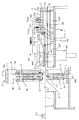
切断加工装置Aは、図1、図2、図4、図5に示すように支持台BのY軸線方向の前方側に切断加工機1およびテーブル面tを基準面とするテーブルTを設置し、支持台BにワークWを解除可能にクランプする移動装置2をY・X軸線方向に制御動可能で且つθ方向に補正動可能に設け、更に移動装置2の待機位置にインデックステーブル3を設置した構成になっている。
As shown in FIGS. 1, 2, 4, and 5, the cutting apparatus A has a cutting
前記支持台Bは、図1〜図3に示すように、切断加工機方向に平行なガイドレールGLを立設して、そのガイドレールGLで移動装置2をY軸線方向に制御動可能にしている。
As shown in FIGS. 1 to 3, the support base B is provided with a guide rail GL which is parallel to the cutting machine direction, and the moving
前記移動装置2は、図2、図3に示すように、前記ガイドレールGLにスライド可能に係合する門形体12と、その門形体12にY軸線方向に制御動可能に連結されθ方向にも制御動可能になっている支持部22と、その支持部22にX軸線方向に制御動可能に支持されたクランパ32等から構成されている。
As shown in FIGS. 2 and 3, the moving
前記門形体12は、その天板部12aから下方に垂設した螺合用アーム12bに、前記支持台Bに設置したサーボモータM1を駆動源として軸受けされたボールネジmを螺嵌して、支持部22と共にクランパ32をY軸線方向に制御動させるようになっている。
The gate-shaped
前記支持部22は、図3に示すように正面視逆L形状を呈する支持体22aと、同様に正面視逆L形状を呈する中間支体22bと、クランパ支体22cとを備えている。
前記支持体22aは、その水平板部22a’を前記門形体12の天板部12aにθ方向に回動可能に軸止し、その水平板部22a’から延設する腕部22a’−1をサーボモータM2で押動してθ方向の回動量を制御可能とし、垂直板部22a”表面にガイドレールGLを縦設している。
中間支体22bは、垂直面部22b’裏面に設けた突条22b’−1を前記縦設されたガイドレールGLに係合すると共に、水平面部22b”に、下端が支持体22aの水平板部22a’に上面に突き当る高さ調整ネジ100を螺合して前記支持体22aに対して高さ調整可能になっている。
クランパ支体22cには、ガイドレールGL、GLを左右に一対間隔をおいて横設し、そのガイドレールGL、GLに前記中間支体22bの垂直面部22b’に突設した突部22b’−2がX軸線方向に制御動可能に係合し、中間支体22bの端面に設けたアクチュエータM3でX軸線方向に制御動するように構成されている。
As shown in FIG. 3, the
The
The intermediate supporting
The
クランパ32は、図3に示すように前記するクランパ支体22cの先端左右端からY軸線方向、即ち切断加工機方向を向いて、クランパ体32a、32aを延設した構成になっている。
As shown in FIG. 3, the
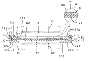
前記ワークホルダ用シートWHは、図7等に示すように金属板、プラスチック板、紙繊維に合成樹脂を含浸した合成紙等切断可能、切断不能を問わず0.1〜0.3mm程度の薄肉な所定の平面積(矩形状(好ましくは正方形))に形成してなり、ワークWである生素地段階(セラミックスグリーンシート間に所定の電極等の導体層を印刷して多層状に積層した)の各種積層基板の外形と同形もしくはほぼ同形の面積の孔W1を開設した孔面積を異にする複数タイプが製作用意されている。
また、生ゴム、合成ゴム等の弾性のある膜板で形成されていても良いものであるが、伸びの少ない腰のある材料で成形するのが好ましいものである。
As shown in FIG. 7 and the like, the work holder sheet WH has a thin thickness of about 0.1 to 0.3 mm regardless of whether it can be cut or cannot be cut, such as a metal plate, a plastic plate, or a synthetic paper in which a paper fiber is impregnated with synthetic resin. Formed in a predetermined flat area (rectangular shape (preferably square)), raw material stage that is the work W (a conductive layer such as a predetermined electrode is printed between the ceramic green sheets and laminated in a multilayer shape) A plurality of types having different hole areas in which holes W1 having the same or substantially the same shape as the outer shapes of the various laminated substrates are provided are prepared.
Further, although it may be formed of an elastic film plate such as raw rubber or synthetic rubber, it is preferable to mold it with a low-stretch material.
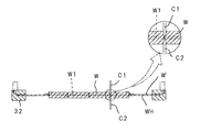
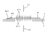
前記ワークWには、その表面や端面等に図8に示すように所定ピッチでマークWMが付されており、該当する面積の孔W1を開孔しワークホルダ用シートWHのその孔W1に挿入した後、コーナー等を前記ワークホルダ用シートWHに剥離可能なテープ(仮止手段)W2で仮止めされている。
このワークWが仮止めされるワークホルダ用シートWHは、このワークWを挟んで同軸上に備設する上下一対の各々の切断刃C1、C2でハーフカットする際、各々の切断刃C1、C2に接触しないようにワークW厚の中途域(好ましくは中間)に位置するように仮止めされて、ワーク支持構造を構成している。
As shown in FIG. 8, the workpiece W is provided with marks WM at a predetermined pitch as shown in FIG. 8, and a hole W1 having a corresponding area is opened and inserted into the hole W1 of the workpiece holder sheet WH. After that, the corners and the like are temporarily fixed to the work holder sheet WH by a tape (temporary fixing means) W2 that can be peeled off.
The workpiece holder sheet WH on which the workpiece W is temporarily fixed is cut half by the pair of upper and lower cutting blades C1 and C2 provided coaxially with the workpiece W interposed therebetween. The workpiece support structure is configured by being temporarily fixed so as to be located in the middle region (preferably in the middle) of the workpiece W so as not to contact the workpiece.
そして、前記ワークホルダ用シートWHには、仮止めされたワークW周囲に所要幅寸法の環状板部W’を残してその縁に耐強度を付与するために縁部材4が設けられ、その縁部材4を移動装置2先端のクランパ32で解除可能にクランプして、その移動装置2の機能でハーフカット対象となるワークWを制御動できるようになっている。
尚、ワークWの裏面は、ワークホルダ用シートWHに仮止めした状態で前記縁部材4の下面と同一高さもしくはそれより若干低い高さになるように形成されている。
The work holder sheet WH is provided with an
In addition, the back surface of the workpiece W is formed so as to have the same height as the lower surface of the
クランパ体32aは、図3、図7等に示すように水平片部32a’−1を前記ワークホルダ用シートWHの縁部材4における左右の枠体14、14外半部用の載承片とするL形片32a’と、そのL形片32a’の立ち上がり片部32a’−2上端に回動可能に軸着した回動片32a”とで左右の枠体14、14を挟持可能とし、その回動片32a”に開閉用のアクチュエータM4を連絡して、クランプを解除可能にしている。
そして、図1に示すように切断加工機1のテーブルTの手前位置である待機時のワークW直下にはインデックステーブル3が上下動可能に設置されている。
As shown in FIG. 3, FIG. 7, etc., the
As shown in FIG. 1, an index table 3 is installed so as to be movable up and down just below the workpiece W during standby, which is a position before the table T of the cutting
前記インデックステーブル3は、前記移動装置2のクランパ32で解除可能にクランプされる待機状態のワークWを保持するワークホルダ用シートWHの縁部材4における前後の枠体14、14を載置する高さ位置から所定高さまで上昇し、その上昇高さ位置で90度回動可能に構成してなり、テーブル上下用のシリンダと回転モータからなるアクチュエータM5を作動させて、前記回動片32a”を上方に回動したクランプ解除状態で移動装置2に干渉しないようにワークWを上方に上昇させ、その高さ位置でワークWを90度回転させ、再び下降させて再度左右の枠体14、14を移動装置2にクランプできるようになっている。
The index table 3 is a height on which the front and
前記テーブルTは、図1、図4等に示すように前記待機状態のワークWのY軸線方向前方位置にインデックステーブル3と同一高さ位置に縁部材4における左右の枠体14、14の内半部下面間の横幅寸法をもって水平状に設けられており、サーボモータM1を駆動させて移動装置2をY軸線方向に前進させると、インデックステーブル3からワークW裏面全面が摺接するように乗り移らせることができるようになっている。
尚、前記の高さ調整ネジ100の進退で、中間支体22b、クランパ支体22c、クランパ32と共に、ワークWが高さ調整可能であるので、ワークWの肉厚に応じて高さ調整して、ワークW裏面全面をテーブル面tに摺接するように乗り移らせることができるようになっている。
As shown in FIGS. 1, 4, etc., the table T is located at the front position in the Y-axis direction of the workpiece W in the standby state and at the same height as the index table 3. The horizontal width between the lower surfaces of the half portions is provided horizontally, and when the servo motor M1 is driven to move the moving
Since the height of the workpiece W can be adjusted together with the
前記切断加工機1は、図1、図2、図4、図5等に示すように本体枠11の左右枠11a、11a内面の上半部、下半部に外側ガイドレールGL、GL各々を縦設し、本体枠11の上枠11bと下枠11cに各々個別に設けたサーボモータM6、M6を駆動源とするボールネジmで連結される上Z軸線サドル21、下Z軸線ラム31を上枠11bの真下、下枠11cの真上に各々配設し、上Z軸線サドル21、下Z軸線ラム31の両端に前記ガイドレールGL、GLに摺動可能に外嵌合する案内部21a、31aを突設して、上Z軸線サドル21、下Z軸線ラム31を上下スライド可能とし、上Z軸線サドル21を下面を開放した内部中空に形成すると共にその下端に上ストリッパST1を設け、上Z軸線サドル21内面に設けたガイドレールGL、GLに上Z軸線ラム41をスライド可能に係合すると共に上Z軸線サドル21の上端に設けたサーボモータM7にその上Z軸線ラム41に連結し、該上Z軸線ラム41にカッターホルダCHを介して上切断刃C1を、また下Z軸線ラム31にカッターホルダCHを介して下切断刃C2を各々取付け、更に本体枠11における左右枠11a、11aの途中にワークWの表面縁に所定ピッチ毎に施したマークWMを撮像するマーク位置検出手段5であるカメラを出入り可能に装設し、更にそのテーブルTにおいて、上ストリッパST1と対応してワーク当たり面である下ストリッパST2をテーブルTと同一高さに移動不能に固定的に設けている。
また、切断加工機1は、上下切断刃C1、C2相互の刃幅方向に位置ズレを検出する第1刃先検出手段D1と、切断刃C1、C2の刃渡り方向の傾斜具合を検出する第2刃先検出手段D2とを具備している。
この第1刃先検出手段D1は、切断加工作業の前段階でサーボモータM6、M6、M7を制御して、刃先同士を接近もしくは当接間係にした状態の両刃先を撮像し、画像回析によって位置ズレを検出するようになっている。本実施の形態では前記マーク位置検出手段5であるカメラを使用して、両刃先の刃幅方向の位置ズレを検出するようになっている。本実施の形態では前記マーク位置検出手段5であるカメラを上下回動可能とし、上方に所要の角度で回動させて両刃先を撮像するようになっている。
第2刃先検出手段D2は、図2等に示すようにテーブルTに設けた光センサーやカメラであり、X軸線方向に走行してテーブル面tやストリッパST1、ST2に対する刃先の平行度を検出するようになっている。
前記検出結果で、カッターホルダCHに対する切断刃C1、C2の取付が微調整される。
また、前記切断加工機1は、上Z軸線ラム41、下Z軸線ラム31に設けたセットポスト51をカッターホルダCHにも開孔したセットポスト孔61に密嵌合して、ダイセットを構成するようになっている。
この実施の形態では、前記テーブル面tまたは下ストリッパST2表面、もしくはそのテーブル面tと下ストリッパST2表面とを加熱手段(図示せず)で加熱して、ハーフカット対象であるワークWを加熱して柔らかくして切断し易くしている。
前記上下一対の切断刃C1、C2は、前記最も大形な孔W1に仮止めされるワークWの幅寸法より長いが平行する枠体14、14間よりも短い所要長さ刃渡り長さである。
As shown in FIGS. 1, 2, 4, 5, etc., the cutting
Further, the cutting
The first cutting edge detection means D1 controls the servo motors M6, M6, and M7 in the previous stage of the cutting work, and images both cutting edges in a state in which the cutting edges are close to or in contact with each other, and image diffraction is performed. The position shift is detected by. In the present embodiment, a camera which is the mark position detecting means 5 is used to detect a positional deviation in the blade width direction of both blade edges. In the present embodiment, the camera that is the mark position detecting means 5 can be turned up and down, and is rotated upward at a required angle to image both cutting edges.
The second blade edge detection means D2 is an optical sensor or camera provided on the table T as shown in FIG. 2 and the like, and travels in the X-axis direction to detect the parallelism of the blade edge with respect to the table surface t and the strippers ST1 and ST2. It is like that.
Based on the detection result, the attachment of the cutting blades C1 and C2 to the cutter holder CH is finely adjusted.
Further, the cutting
In this embodiment, the table surface t or the lower stripper ST2 surface, or the table surface t and the lower stripper ST2 surface is heated by a heating means (not shown) to heat the workpiece W to be half cut. Soft and easy to cut.
The pair of upper and lower cutting blades C1 and C2 have a required length over which the blade W is longer than the width of the workpiece W temporarily fixed in the largest hole W1, but shorter than between the
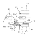
以上のように構成されている切断加工装置Aは、図1に示す移動装置2先端のクランパ32でワークホルダ用シートWH周縁の縁部材4の左右枠体14、14外半部を解除可能にクランプしている待機状態でサーボモータM1を作動させて、テーブルT上をワークWが摺接するように、所定送りピッチ、即ちマークWMのピッチをもってワークホルダ用シートWHをY軸線方向に制御動する度に、図6に示すように出入りするマーク位置検出手段(カメラ)5で表面の平行縁部同一位置に存在するマークWMを撮像し、画像処理して、各々のマークWMの記憶座標値X0−Y0、X0−Y0と、実測座標値X1−Y1、X1−Y1とを比較演算して得られた送り誤差の修正データをもって移動装置2、即ちワークホルダ用シートWHをY軸線方向、θ方向に制御して送り誤差によるマークWMの位置を補正してから、マーク位置検出手段(カメラ)5を後退させ、図7に示すように上ストリッパST1をワークWの表面に接近もしくは接触するように制御によって下降させてから、上下切断刃C1、C2を、ワークWの表裏同一位置から切込量V1、V1を分担するように同期して制御動させて、ワークホルダ用シートWHの表面、裏面に接触する寸前まで同時または時間差をおいて切込みを入れる。
例えば、ワークWの肉厚が0.4mmにあっては、例えば肉厚を0.1mm程度とするワークホルダ用シートWHを使用し、またワークWの肉厚を1mm〜5mmとするものにあっては、例えば肉厚を0.3mm程度のワークホルダ用シートWHを使用して、上下一対の切断刃C1、C2の切込分担量を上切断刃C1の刃先がワークホルダ用シートWHの表面に、また下切断刃C2の刃先がワークホルダ用シートWHの裏面に各々接触する寸前に設定して、前記のように切込むようになっている。
前記マーク位置検出手段5でのマークWMの撮像、θ方向への制御動、マーク位置検出手段5の所定位置への復帰、上ストリッパST2の所定高さ位置までの下降、切込みを、マークピッチでのワークホルダ用シートWMのY軸線方向への制御動の度に行う。
そして、左右の枠体14、14がインデックステーブル3に載承されるようにY軸線方向に後退させた後、クランパ32を解除してから、インデックステーブル3を上昇させ90度回動し下降させて再びワークホルダ用シートWM周縁の左右の枠体14、14外半部を挟持させてから上述のように所定送りピッチ、即ちマークWHのピッチをもってワークホルダ用シートWHをY軸線方向に制御動する度に、マーク位置検出手段5でのマークWHの撮像、θ方向への制御動、マーク位置検出手段5の所定位置への復帰、上ストリッパST1の所定高さ位置までの下降、切込みを、マークピッチでのワークホルダ用シートWHのY軸線方向への制御動の度に行って、ワークWを、端切れを作り出さずに碁盤目状にハーフカットする(図8参照)。
上切断刃C1をワークWから抜取る時まで上ストリッパST1はワークWの表面に接近または接触させて使用すること当然である。
また、前記仮止め手段であるテープW2を剥離すれば、ワークホルダ用シートWHは耐用期まで使用可能に碁盤目状にハーフカットされたワークWから分離される。
碁盤目状にハーフカットされたワークWは、焼成後にその切込み部分から切断砥石(図示せず)で分断して、平面視矩形状の積層基板や積層型電子部品からなるチップ状物を得るようになっている。
The cutting device A configured as described above can release the outer half portions of the left and
For example, if the workpiece W has a thickness of 0.4 mm, a workpiece holder sheet WH having a thickness of about 0.1 mm is used, and the workpiece W has a thickness of 1 mm to 5 mm. For example, using a work holder sheet WH having a thickness of about 0.3 mm, the cutting edge of the pair of upper and lower cutting blades C1 and C2 is the surface of the work holder sheet WH. In addition, the cutting edge of the lower cutting blade C2 is set immediately before it comes into contact with the back surface of the work holder sheet WH, and is cut as described above.
Mark mark WM is picked up by mark position detection means 5, control movement in the θ direction, return of mark position detection means 5 to a predetermined position, lower stripper ST2 to a predetermined height position, and cutting at mark pitch. This is performed each time the work holder sheet WM is controlled in the Y-axis direction.
Then, after the left and
It is natural that the upper stripper ST1 is used by approaching or contacting the surface of the workpiece W until the upper cutting blade C1 is removed from the workpiece W.
Further, when the tape W2 as the temporary fixing means is peeled off, the work holder sheet WH is separated from the work W that has been half-cut in a grid pattern so that it can be used until the service life.
The workpiece W that has been half-cut into a grid pattern is cut off from the cut portion with a cutting grindstone (not shown) after firing to obtain a chip-like object made of a laminated substrate or a laminated electronic component having a rectangular shape in plan view. It has become.
従って、この第1の実施の形態では、ワークWをハーフカットする時の上切断刃C1の押し下げ力を受けてワークWが変形するのを防止し、またワークホルダ用シートWHを切断することなくワークWを全幅に亘ってハーフカットすることができる。 Therefore, in the first embodiment, the workpiece W is prevented from being deformed by receiving the pressing force of the upper cutting blade C1 when the workpiece W is half-cut, and the workpiece holder sheet WH is not cut. The workpiece W can be half-cut across the entire width.
次に、切断加工方法を実施する切断加工装置の形態例を図9に基づいて説明すると、この実施の形態のクランパ32は、縁部材4におけるY軸線方向前後の枠体14、14を解除可能にクランプしたものである。
クランパ32は、詳細には前記クランプ支体22cに、各Y軸線方向に平行な構成片32b’を平板状とし、その構成片32b’両端間を連設する構成片32b”をL型状とする矩形枠32bを切断加工機方向に延設し、その前後の構成片32b”に回動体32a”を軸着する一方、その前後の構成片32b”の水平片部32b”−1に対応して、その水平片部32b”−1を収容する凹窪部14aを縁部材4における前記前後の枠体14、14に凹設して、前後の構成片32b”、32b”と、その回動体32a”、32a”とで前後のクランパ体32a、32aを構成し、前後の構成片32b”、32b”における水平片部32b”−1、32b”−1を各々凹窪部14a、14aに収容した状態で、前後の水平片部32b”−1、32b”−1とその回動体32a”、32a”とで前後の枠体14、14を挟持可能にして、ワークWの裏面と同一高さ位置またはそれよりも高い位置に前記する前後の構成片32b”の水平片部32b”−1が位置するように構成されている。
また、ワークWの裏面は、前記第1の実施の形態と同様にワークホルダ用シートWHに仮止めした状態で縁部材4の下面と同一高さもしくはそれより若干低い高さになるようにしてある。
Next, an example of a cutting apparatus that performs the cutting method will be described with reference to FIG. 9. The
Specifically, the
Further, the back surface of the workpiece W is set to the same height as the lower surface of the
それ故、前記第1の実施の形態と同様に、移動装置2をY軸線方向に前進させると、インデックステーブル3からワークW裏面全面が摺接するようにテーブルTに乗り移るようになっている。
Therefore, as in the first embodiment, when the moving
次に、切断加工方法を実施する切断加工装置の形態例を図10に基づいて説明すると、この実施の形態はワーク支持構造の変形例を示すものである。
この実施の形態は、ワークホルダ用シートWHを弾性変形を許容する合成樹脂材等で成形している。
このようにワークホルダ用シートWHを弾性変形を許容する合成樹脂材で成形した場合には、その弾性変形機能でワークW裏面がテーブル面tに対して完全に摺接する関係になっていない場合でもワークW自重で弾性変形しテーブル面tに摺接することが可能になり、ワークホルダ用シートWHのワークWに対する取付位置に高精度を要求されなくなる。
The explanation will be made based on the embodiment of the cutting apparatus for carrying out the cutting method in FIG. 10, this embodiment shows a modification of the workpiece support structure.
In this embodiment, the work holder sheet WH is formed of a synthetic resin material or the like that allows elastic deformation.
Thus, when the workpiece holder sheet WH is formed of a synthetic resin material that allows elastic deformation, even when the back surface of the workpiece W is not completely in sliding contact with the table surface t due to its elastic deformation function. The workpiece W can be elastically deformed by its own weight and slidably contact with the table surface t, so that a high accuracy is not required for the attachment position of the workpiece holder sheet WH with respect to the workpiece W.
次に、切断加工方法を実施する切断加工装置の形態例を図11に基づいて説明すると、この実施の形態は、ワークW厚の増減間係なくクランパ32を共用できるワーク支持構造を示している。
ワークホルダ用シートWHの縁部材4は、前記ワークホルダ用シートWHの縁に設けた縁体24と、移動装置2のクランパ32でワークWを間接的にクランプする本体34とを備えている。
Next, an example of a cutting apparatus that performs the cutting method will be described with reference to FIG. 11. This embodiment shows a work support structure that can share the
The
本体34は、図示するように移動装置2のクランパ32で解除可能にクランプされる矩形部34aの内端上部から内向きにアーム板部34bを突設して、アーム板部34b下方にスペースSを確保し、そのアーム板部34bに適宜間隔をおいて凹部34b’を凹設し、該凹部34b’底に通孔を開孔している。
As shown in the figure, the
一方、前記アーム板部34bに対応する左右の縁体24、24部分には螺子孔24aを開孔し、前記凹部34b’に頭部が収容されるネジ6の軸部をその螺子孔24aに螺嵌して、ネジ6の回動で前記スペースSを利用してワークWの高さを調整している。
この構成を採用すると、切断対象となるワークW厚が変化しても、クランパ32位置を変化させずにワークWを切断加工機1のテーブル面を基準面とするテーブルに摺接させることができる。
On the other hand, screw holes 24a are opened in the left and
By adopting this configuration, even if the thickness of the workpiece W to be cut changes, the workpiece W can be slid in contact with the table whose reference plane is the table surface of the cutting
次に、図12、図13に示す形態例を説明すると、この形態は、前記縁部材4で周縁を補強することなく移動装置2のクランパ32でワークホルダ用シートWHを直接解除可能にクランプするワーク支持構造を示している。
Next, the embodiment shown in FIGS. 12 and 13 will be described. In this embodiment , the work holder sheet WH is directly releasably clamped by the
更に、図14、図15に示す形態例を説明すると、ワークWを全幅に亘ってフルカットする場合のワーク支持構造を示し、ワークホルダ用シートWHを切断可能な材料(例えば合成紙(紙繊維に合成樹脂を含浸した))で成形した点以外は前記する第1の実施の形態と同様である。
この形態では、移動装置2のクランパ32で解除可能にクランプすると共に上下一対の切断刃C1、C2両端部が環状板部W’の上方に臨む態様にして、ワークWを水平方向に所定ピッチ宛移動させてその上下一対の切断刃C1、C2でワークWと共にワークホルダ用シートWHを完全切断(フルカット)するようになっている。
この形態の場合には、前記する実施の形態と同様に端切れを作りだすことなくワークWを全幅に亘って碁盤目状にフルカットしてチップ状物を得た後、そのワークホルダ用シートWHは廃棄される。
尚、ワークWを水平に移動させて、ワークを90度水平方向に回動させる前、90度回動させた後にその切断刃C1、C2を作動させて切断すること前記する実施の形態と同様である。
また、図面では、ワークホルダ用シートWHをクランパ32で直接クランプした状態を示している。
Further, FIG. 14, referring to an embodiment shown in FIG. 15 shows the workpiece support structure in the case of full cut over the workpiece W to the full width, which can cut the sheet WH for work holder material (such as synthetic paper (paper fiber The method is the same as that of the first embodiment described above except that it is impregnated with synthetic resin.
In this configuration , the workpiece W is horizontally clamped to a predetermined pitch in such a manner that both ends of the pair of upper and lower cutting blades C1 and C2 face above the annular plate portion W ′ while being releasably clamped by the
In the case of this embodiment , the workpiece holder sheet WH is obtained by cutting the workpiece W into a grid pattern across the entire width without producing a cut as in the above-described embodiment, and obtaining a chip-like object. Discarded.
In addition, the workpiece W is moved horizontally, and the workpiece is cut by operating the cutting blades C1 and C2 after turning the workpiece 90 degrees before and after turning the workpiece 90 degrees horizontally. It is.
Further, the drawing shows a state where the work holder sheet WH is directly clamped by the
図16〜図19は、ワークホルダ用シートの例の斜視図を示し、図16は、直接クランプする例、図17は、直接クランプするワークホルダ用シートWHに開孔した孔W1のコーナーにワーク載せ段部W1’を段設形成して、そのワーク載せ段部W1’にワークWを剥離可能に載置する例を、図18は、図6や図7で示す例を、図19は、図11の例を示している。 16 to 19 show perspective views of examples of the workpiece holder sheet, FIG. 16 shows an example of direct clamping, and FIG. 17 shows a workpiece at the corner of the hole W1 opened in the workpiece holder sheet WH to be directly clamped. FIG. 18 shows an example shown in FIG. 6 or FIG. 7, and FIG. 19 shows an example in which the loading step W1 ′ is stepped and the workpiece W is detachably placed on the workpiece loading step W1 ′. The example of FIG. 11 is shown.
また、図20は矩形枠状のワークホルダWH1の上面に周縁部を載置してテープ等の仮止手段W2でワークWを着脱可能に保持したワーク支持構造を使用して上下切断刃C1、C2で分担してフルカットまたはハーフカットする切断加工方法を実施する切断加工装置の要部を示すものであり、図20はその切断加工時の状態を部分的に拡大して示している。
図20は、前記形態の切断加工機においてワーク当たり面である下ストリッパST2を、テーブルTを刳り貫いて下切断刃C2と独立して上下高さ制御可能に設けている。テーブルT上を所定ピッチ宛移動する際にワークホルダWH1との干渉を避けるべく、その下ストリッパST2を制御動させて、下位に位置させる。そしてワークカット時に下ストリッパST2をワークW裏面高さ位置まで制御動させて、上切断刃C1切り込み時の上切断刃C1によるワークWの押し下げを下ストリッパST2で防止し、そして下切断刃C2切り込み時の下切断刃C2によるワークWの押し上げをワークWの表面に接近または接触するように制御動させた上ストリッパST1で防止するように構成されている。
上切断刃C1をワークWから抜取る時まで上ストリッパST1はワークWの表面に接近または接触させ、下切断刃C2をワークWから抜取る時にも下ストリッパST2はワークWの裏面の高さ位置を維持されること前記形態と同じである。
尚、図20で示す実施の形態は、上下切断刃C1、C2を同時に切り込んだり、時間差をおいて切り込むものである。
FIG. 20 shows an upper and lower cutting blade C1 using a workpiece support structure in which a peripheral portion is placed on the upper surface of a rectangular frame-shaped workpiece holder WH1 and the workpiece W is detachably held by temporary fixing means W2 such as a tape. FIG. 20 shows an essential part of a cutting apparatus for carrying out a cutting method that performs full cutting or half cutting by sharing with C2, and FIG. 20 shows a partially enlarged state during cutting.
FIG. 20 is provided with a lower stripper ST2 which is a work contact surface in the cutting machine of the above-described form , penetrating the table T so that the vertical height can be controlled independently of the lower cutting blade C2. In order to avoid interference with the work holder WH1 when moving to the predetermined pitch on the table T, the lower stripper ST2 is controlled to be positioned at a lower position. Then, when the workpiece is cut, the lower stripper ST2 is controlled to move to the height position of the back surface of the workpiece W to prevent the workpiece W from being pushed down by the upper cutting blade C1 when the upper cutting blade C1 is cut, and the lower cutting blade C2 is cut. The upper stripper ST1 that is controlled so as to approach or come into contact with the surface of the workpiece W is prevented from being pushed up by the lower cutting blade C2 at that time.
The upper stripper ST1 approaches or contacts the surface of the workpiece W until the upper cutting blade C1 is removed from the workpiece W, and the lower stripper ST2 is also positioned at the height of the back surface of the workpiece W when the lower cutting blade C2 is removed from the workpiece W. Is the same as the above embodiment .
In the embodiment shown in FIG. 20, the upper and lower cutting blades C1 and C2 are cut at the same time, or cut with a time difference.
A:切断加工装置 1:切断加工機
WH:ワークホルダ用シート W:ワーク
W1:孔 W2:仮止手段(テープ)
C1、C2:上下切断刃 2:移動装置
32:クランパ T:テーブル
ST1:上ストリッパ ST2:ワーク当たり面(下ストリッパ)
3:インデックステーブル WM:マーク
5:マーク位置検出手段 4:縁部材
24:縁体 34:本体
W’:環状板部 WH1:ワークホルダ
t:テーブル面 D1:第1刃先検出手段
D2:第2刃先検出手段 61:セットポスト孔
51:セットポスト 31、41:ラム(上Z軸線ラム、下Z軸線ラム)
CH:カッターホルダ
A: Cutting device 1: Cutting machine WH: Work holder sheet W: Work W1: Hole W2: Temporary fixing means (tape)
C1, C2: Upper and lower cutting blades 2: Moving device 32: Clamper T: Table ST1: Upper stripper ST2: Workpiece contact surface (lower stripper)
3: Index table WM: Mark 5: Mark position detecting means 4: Edge member 24: Edge body 34: Main body W ′: Annular plate portion WH1: Work holder t: Table surface D1: First cutting edge detecting means D2: Second cutting edge Detection means 61: Set post hole 51: Set
CH: Cutter holder
Claims (9)
前記切断加工機は、前記上切断刃の切り込み位置周囲でワークの表面に近接又は接触する上ストリッパと、当該上ストリッパと対応して前記ワークの裏面側の当たり面となる下ストリッパとを備え、
前記上ストリッパを前記上切断刃とは独立して上下高さ制御可能にすると共に、
前記ワークホルダをワークの厚さよりも薄肉なワークホルダ用シートで構成し、
前記ワークホルダ用シートは、ワークの外形と同形もしくはほぼ同形の孔を備え、前記ワークホルダ用シートの孔にワークを挿入して当該ワークを前記ワークホルダ用シートに仮止めし、前記上切断刃と前記下切断刃とでワークをハーフカットする際に前記上切断刃と前記下切断刃の両方が前記ワークホルダ用シートに接触しないように、前記ワークホルダ用シートをワーク厚の中途域に位置させており、
前記移動装置が前記ワークホルダ用シートをクランプして移動させる際に前記切断加工機のテーブル面にワーク裏面全面が摺接するように構成し、前記下ストリッパを前記切断加工機のテーブル面高さに固定していることを特徴とする切断加工装置。 A workpiece holder for removably supporting the workpiece, a moving device that clamps the workpiece holder and moves the workpiece holder by a predetermined pitch, and a cutting machine having an upper cutting blade and a lower cutting blade, the moving device comprising the workpiece In the cutting apparatus that half-cuts the workpiece with the upper cutting blade and the lower cutting blade each time the holder is moved by a predetermined pitch,
The cutting machine includes an upper stripper that is close to or in contact with the surface of the workpiece around the cutting position of the upper cutting blade, and a lower stripper that corresponds to the upper stripper and serves as a contact surface on the back surface side of the workpiece,
While allowing the upper stripper to control the vertical height independently of the upper cutting blade,
The work holder is composed of a work holder sheet that is thinner than the thickness of the work,
The workpiece holder sheet has a hole having the same shape or substantially the same shape as the outer shape of the workpiece, the workpiece is inserted into the hole of the workpiece holder sheet, the workpiece is temporarily fixed to the workpiece holder sheet, and the upper cutting blade When the workpiece is half-cut with the lower cutting blade, the workpiece holder sheet is positioned in the middle of the workpiece thickness so that both the upper cutting blade and the lower cutting blade do not contact the workpiece holder sheet. Let
When the moving device clamps and moves the workpiece holder sheet, the entire back surface of the workpiece is in sliding contact with the table surface of the cutting machine, and the lower stripper is set to the height of the table surface of the cutting machine. A cutting apparatus characterized by being fixed .
前記切断加工機は、前記上切断刃の切り込み位置周囲でワークの表面に近接又は接触する上ストリッパと、当該上ストリッパと対応して前記ワークの裏面側の当たり面となる下ストリッパとを備え、
前記上ストリッパを前記上切断刃とは独立して上下高さ制御可能にすると共に、
前記ワークホルダをワークの厚さよりも薄肉なワークホルダ用シートで構成し、
前記ワークホルダ用シートは、ワークの外形と同形もしくはほぼ同形の孔を備え、前記ワークホルダ用シートの孔にワークを挿入して当該ワークを前記ワークホルダ用シートに仮止めし、前記上切断刃と前記下切断刃とで分担してワークをフルカットし、
前記移動装置が前記ワークホルダ用シートをクランプして移動させる際に前記切断加工機のテーブル面にワーク裏面全面が摺接するように構成し、前記下ストリッパを前記切断加工機のテーブル面高さに固定していることを特徴とする切断加工装置。 A workpiece holder for removably supporting the workpiece, a moving device that clamps the workpiece holder and moves the workpiece holder by a predetermined pitch, and a cutting machine having an upper cutting blade and a lower cutting blade, the moving device comprising the workpiece In the cutting device that fully shares the work by sharing the upper cutting blade and the lower cutting blade each time the holder is moved by a predetermined pitch,
The cutting machine includes an upper stripper that is close to or in contact with the surface of the workpiece around the cutting position of the upper cutting blade, and a lower stripper that corresponds to the upper stripper and serves as a contact surface on the back surface side of the workpiece,
While allowing the upper stripper to control the vertical height independently of the upper cutting blade,
The work holder is composed of a work holder sheet that is thinner than the thickness of the work,
The workpiece holder sheet has a hole having the same shape or substantially the same shape as the outer shape of the workpiece, the workpiece is inserted into the hole of the workpiece holder sheet, the workpiece is temporarily fixed to the workpiece holder sheet, and the upper cutting blade And the lower cutting blade to fully cut the workpiece,
When the moving device clamps and moves the workpiece holder sheet, the entire back surface of the workpiece is in sliding contact with the table surface of the cutting machine, and the lower stripper is set to the height of the table surface of the cutting machine. A cutting apparatus characterized by being fixed .
前記移動装置がワークを所定ピッチずつ移動させる度に、前記マークの位置ズレを前記マーク位置検出手段が検出し、前記移動装置を前記切断加工機への移動方向であるY軸線方向、θ方向またはY軸線方向、θ方向、X軸線方向に補正動可能に構成されていることを特徴とする請求項1又は2記載の切断加工装置。 The cutting machine comprises a mark position detecting means for detecting marks attached to the workpiece at a predetermined interval,
Each time the moving device moves the work by a predetermined pitch, the mark position detecting means detects the mark position deviation, and the moving device moves in the Y-axis direction, θ direction, The cutting apparatus according to claim 1 or 2 , wherein the cutting apparatus is configured to be capable of correction movement in the Y axis direction, the θ direction, and the X axis direction .
Priority Applications (4)
| Application Number | Priority Date | Filing Date | Title |
|---|---|---|---|
| JP2004380812A JP4780752B2 (en) | 2004-12-28 | 2004-12-28 | Cutting device |
| TW094146103A TW200635727A (en) | 2004-12-28 | 2005-12-23 | Method of cutting, cutting device, and work piece supporting structure used in the cutting device |
| CN2005101377913A CN1796062B (en) | 2004-12-28 | 2005-12-28 | Cut processing method, cut processing apparatus and work-piece supporting construction used with said apparatus |
| KR1020050131829A KR101310693B1 (en) | 2004-12-28 | 2005-12-28 | Cut working apparatus |
Applications Claiming Priority (1)
| Application Number | Priority Date | Filing Date | Title |
|---|---|---|---|
| JP2004380812A JP4780752B2 (en) | 2004-12-28 | 2004-12-28 | Cutting device |
Publications (2)
| Publication Number | Publication Date |
|---|---|
| JP2006181704A JP2006181704A (en) | 2006-07-13 |
| JP4780752B2 true JP4780752B2 (en) | 2011-09-28 |
Family
ID=36735172
Family Applications (1)
| Application Number | Title | Priority Date | Filing Date |
|---|---|---|---|
| JP2004380812A Expired - Fee Related JP4780752B2 (en) | 2004-12-28 | 2004-12-28 | Cutting device |
Country Status (4)
| Country | Link |
|---|---|
| JP (1) | JP4780752B2 (en) |
| KR (1) | KR101310693B1 (en) |
| CN (1) | CN1796062B (en) |
| TW (1) | TW200635727A (en) |
Cited By (1)
| Publication number | Priority date | Publication date | Assignee | Title |
|---|---|---|---|---|
| CN107042534A (en) * | 2017-06-14 | 2017-08-15 | 苏州宇希新材料科技有限公司 | A kind of heat insulation plate for building depositing dust device for excising |
Families Citing this family (18)
| Publication number | Priority date | Publication date | Assignee | Title |
|---|---|---|---|---|
| DE102007008258A1 (en) * | 2007-02-20 | 2008-08-21 | Heidelberger Druckmaschinen Ag | Bar breaking device, has right-angled shaft pivotably supported on sides of flat path in housing, and formed with die holder elements as square profile shafts, where stripping tool is fastened to die holder elements |
| DE102007061427B4 (en) * | 2007-12-20 | 2009-11-12 | Airbus Deutschland Gmbh | Apparatus for cutting and handling a substantially planar blank from a CFRP semi-finished product and method |
| JP5563752B2 (en) * | 2008-06-26 | 2014-07-30 | 東京応化工業株式会社 | Coating apparatus and coating method |
| JP5791926B2 (en) * | 2011-03-16 | 2015-10-07 | 株式会社ミマキエンジニアリング | Cutting device and cut data generation program |
| JP5197870B1 (en) * | 2012-02-11 | 2013-05-15 | 株式会社メイク・ア・ボックス | Punching machine balance correction sheet manufacturing method, punching machine balance correction type, punching machine balance correction method, and punching machine balance correction sheet |
| CN102773547A (en) * | 2012-07-23 | 2012-11-14 | 陈道宝 | Z-shaped workpiece shearing machine clamping device |
| ITMI20130113A1 (en) * | 2013-01-25 | 2014-07-26 | Comelz Spa | HOLDING DEVICE FOR MULTILAYER SYNTHETIC MATERIALS ON CUTTING AND SIMILAR TABLES. |
| CN104608162B (en) * | 2014-12-30 | 2016-08-17 | 东莞理工学院 | A kind of numerical control coiled strip vibrating blade cutting equipment |
| CN105690483A (en) * | 2016-03-29 | 2016-06-22 | 江苏通用科技股份有限公司 | Forming machine ultrasonic cut-off knife device with cut-off protection function |
| CN105750614B (en) * | 2016-04-25 | 2018-02-23 | 华中科技大学 | A kind of pulse electromagnetic shear |
| CN110576215B (en) * | 2018-07-23 | 2024-07-19 | 蓝思精密(泰州)有限公司 | Pipe cutting equipment and cutting method |
| CN109082875A (en) * | 2018-10-26 | 2018-12-25 | 江苏四方纺线有限责任公司 | Edge-cutting device is used in a kind of production of textile cloth |
| CN111778706B (en) * | 2020-08-24 | 2022-03-18 | 安徽优优时尚科技有限公司 | Cutting bed cloth is led with integral type and is sent device of tailorring |
| CN112958821A (en) * | 2021-02-04 | 2021-06-15 | 深圳德龙激光智能有限公司 | Battery core tab cutting device |
| CN113172269B (en) * | 2021-04-26 | 2023-12-19 | 江苏立讯机器人有限公司 | Cutting device |
| CN115723260A (en) * | 2022-10-28 | 2023-03-03 | 江苏维福特科技发展股份有限公司 | Sapphire multistation cutting machine |
| CN116213818B (en) * | 2023-03-02 | 2024-07-12 | 江苏新正创机械科技有限公司 | Profiling shearing device for geometric angle of end face of cold-formed profile |
| KR102575676B1 (en) * | 2023-05-24 | 2023-09-06 | 권상현 | Sheet cutting device |
Family Cites Families (11)
| Publication number | Priority date | Publication date | Assignee | Title |
|---|---|---|---|---|
| JPS55131425A (en) * | 1979-03-24 | 1980-10-13 | Murata Mach Ltd | Work processing in shearing machine |
| JP2608969B2 (en) * | 1990-05-31 | 1997-05-14 | ユーエイチティー株式会社 | Work control method in through hole forming |
| CN1022550C (en) * | 1990-09-01 | 1993-10-27 | 杭州橡胶总厂 | Cutting device for tire tread |
| JPH04279229A (en) * | 1991-03-05 | 1992-10-05 | Murata Mach Ltd | Work feeding device for sheet metal working machine |
| CN2141755Y (en) * | 1992-12-10 | 1993-09-08 | 陈明湖 | Cut-off machine |
| US5542325A (en) * | 1994-08-30 | 1996-08-06 | Bane, Iii; Wiliam W. | Sheet cutting apparatus |
| JP3317875B2 (en) * | 1997-05-29 | 2002-08-26 | 住友重機械工業株式会社 | Device and method for holding thin sheet |
| JP3201516B2 (en) * | 1997-07-18 | 2001-08-20 | ユーエイチティー株式会社 | Perforator |
| JP4654334B2 (en) * | 2001-04-13 | 2011-03-16 | Uht株式会社 | Method and apparatus for holding workpiece on workpiece holder |
| JP2002326184A (en) * | 2001-05-01 | 2002-11-12 | Kyodo Seiki:Kk | Cutter |
| JP2004034319A (en) * | 2002-06-28 | 2004-02-05 | Uht Corp | Cutting method for laminated sheet and half-cut device used therein |
-
2004
- 2004-12-28 JP JP2004380812A patent/JP4780752B2/en not_active Expired - Fee Related
-
2005
- 2005-12-23 TW TW094146103A patent/TW200635727A/en unknown
- 2005-12-28 CN CN2005101377913A patent/CN1796062B/en active Active
- 2005-12-28 KR KR1020050131829A patent/KR101310693B1/en active IP Right Grant
Cited By (1)
| Publication number | Priority date | Publication date | Assignee | Title |
|---|---|---|---|---|
| CN107042534A (en) * | 2017-06-14 | 2017-08-15 | 苏州宇希新材料科技有限公司 | A kind of heat insulation plate for building depositing dust device for excising |
Also Published As
| Publication number | Publication date |
|---|---|
| JP2006181704A (en) | 2006-07-13 |
| TW200635727A (en) | 2006-10-16 |
| CN1796062A (en) | 2006-07-05 |
| KR101310693B1 (en) | 2013-09-25 |
| TWI308516B (en) | 2009-04-11 |
| KR20060079749A (en) | 2006-07-06 |
| CN1796062B (en) | 2010-07-07 |
Similar Documents
| Publication | Publication Date | Title |
|---|---|---|
| JP4780752B2 (en) | Cutting device | |
| JP5173885B2 (en) | Scribing apparatus and scribing method | |
| KR101123613B1 (en) | Scribing device and scribing method | |
| US20080118323A1 (en) | Method and apparatus for machining work by cutting tool | |
| KR101786436B1 (en) | Scribing apparatus of the substrate | |
| JP4290784B2 (en) | Glass scriber | |
| TWI391981B (en) | Sheet attachment | |
| US6334745B1 (en) | Apparatus and method for working double sided workpiece | |
| KR20040002757A (en) | Cutting method of laminate and half cut used in the cutting method | |
| KR20160126122A (en) | the coverlay punch unit for protection FPCB | |
| JPH0794846A (en) | Pcb machine | |
| CN202826098U (en) | Break machine | |
| JP2018065214A (en) | Method and device for processing plate material made by stacking thin plates | |
| CN218642633U (en) | Cutting device for substrate | |
| KR20050000605A (en) | Bonding Equipment For Bonding Anisotropic Conductive Film And Drive Chip Of Flat Panel Display | |
| CN109732674A (en) | Digital die-cutting machine and its multitool cut-sytle pollination method, system | |
| CN112440399B (en) | Crystal bar fixing jig | |
| JP3890992B2 (en) | Method and apparatus for forming groove for cutting mother glass substrate | |
| JP2008126323A (en) | Method and apparatus for machining by single point tool | |
| JP5508688B2 (en) | Product carrying method and apparatus | |
| JP3192536U (en) | Substrate scribing equipment | |
| JP2007069477A (en) | Scribe device and indication board manufactured by using the device | |
| JPH07314390A (en) | Cutting device for printed circuit board | |
| CN220457662U (en) | PCBA tool is adjusted to accuracy | |
| CN117961317A (en) | Large-breadth laser processing machine tool |
Legal Events
| Date | Code | Title | Description |
|---|---|---|---|
| A621 | Written request for application examination |
Free format text: JAPANESE INTERMEDIATE CODE: A621 Effective date: 20071130 |
|
| RD02 | Notification of acceptance of power of attorney |
Free format text: JAPANESE INTERMEDIATE CODE: A7422 Effective date: 20071130 |
|
| A977 | Report on retrieval |
Free format text: JAPANESE INTERMEDIATE CODE: A971007 Effective date: 20100413 |
|
| A131 | Notification of reasons for refusal |
Free format text: JAPANESE INTERMEDIATE CODE: A131 Effective date: 20110215 |
|
| A521 | Written amendment |
Free format text: JAPANESE INTERMEDIATE CODE: A523 Effective date: 20110411 |
|
| TRDD | Decision of grant or rejection written | ||
| A01 | Written decision to grant a patent or to grant a registration (utility model) |
Free format text: JAPANESE INTERMEDIATE CODE: A01 Effective date: 20110607 |
|
| A01 | Written decision to grant a patent or to grant a registration (utility model) |
Free format text: JAPANESE INTERMEDIATE CODE: A01 |
|
| A61 | First payment of annual fees (during grant procedure) |
Free format text: JAPANESE INTERMEDIATE CODE: A61 Effective date: 20110704 |
|
| FPAY | Renewal fee payment (event date is renewal date of database) |
Free format text: PAYMENT UNTIL: 20140715 Year of fee payment: 3 |
|
| R150 | Certificate of patent or registration of utility model |
Free format text: JAPANESE INTERMEDIATE CODE: R150 |
|
| LAPS | Cancellation because of no payment of annual fees |