JP4778545B2 - Fluid ejection device - Google Patents
Fluid ejection device Download PDFInfo
- Publication number
- JP4778545B2 JP4778545B2 JP2008270031A JP2008270031A JP4778545B2 JP 4778545 B2 JP4778545 B2 JP 4778545B2 JP 2008270031 A JP2008270031 A JP 2008270031A JP 2008270031 A JP2008270031 A JP 2008270031A JP 4778545 B2 JP4778545 B2 JP 4778545B2
- Authority
- JP
- Japan
- Prior art keywords
- fluid
- channel
- pump chamber
- connection
- ejecting apparatus
- Prior art date
- Legal status (The legal status is an assumption and is not a legal conclusion. Google has not performed a legal analysis and makes no representation as to the accuracy of the status listed.)
- Expired - Lifetime
Links
- 239000012530 fluid Substances 0.000 title claims description 228
- 230000000284 resting effect Effects 0.000 claims description 21
- 230000010349 pulsation Effects 0.000 claims description 13
- 239000011358 absorbing material Substances 0.000 claims description 5
- 239000011810 insulating material Substances 0.000 claims description 4
- 230000000644 propagated effect Effects 0.000 claims description 2
- 210000001519 tissue Anatomy 0.000 description 27
- 230000000694 effects Effects 0.000 description 17
- 238000000034 method Methods 0.000 description 15
- 230000008859 change Effects 0.000 description 10
- 230000007423 decrease Effects 0.000 description 9
- 239000007924 injection Substances 0.000 description 8
- 238000002347 injection Methods 0.000 description 8
- 238000002474 experimental method Methods 0.000 description 7
- 210000000056 organ Anatomy 0.000 description 7
- 239000007788 liquid Substances 0.000 description 6
- 230000008569 process Effects 0.000 description 6
- 238000011038 discontinuous diafiltration by volume reduction Methods 0.000 description 5
- 238000006073 displacement reaction Methods 0.000 description 5
- 238000011156 evaluation Methods 0.000 description 5
- 239000000463 material Substances 0.000 description 5
- 230000000740 bleeding effect Effects 0.000 description 4
- 210000004204 blood vessel Anatomy 0.000 description 3
- 230000006378 damage Effects 0.000 description 3
- 210000004185 liver Anatomy 0.000 description 3
- 239000002504 physiological saline solution Substances 0.000 description 3
- 238000001356 surgical procedure Methods 0.000 description 3
- 230000000007 visual effect Effects 0.000 description 3
- 229920006311 Urethane elastomer Polymers 0.000 description 2
- 230000036760 body temperature Effects 0.000 description 2
- 210000003792 cranial nerve Anatomy 0.000 description 2
- 230000002093 peripheral effect Effects 0.000 description 2
- 229920002379 silicone rubber Polymers 0.000 description 2
- 230000002792 vascular Effects 0.000 description 2
- 210000001835 viscera Anatomy 0.000 description 2
- XLYOFNOQVPJJNP-UHFFFAOYSA-N water Substances O XLYOFNOQVPJJNP-UHFFFAOYSA-N 0.000 description 2
- 229910000838 Al alloy Inorganic materials 0.000 description 1
- 208000005189 Embolism Diseases 0.000 description 1
- 229910001069 Ti alloy Inorganic materials 0.000 description 1
- 238000010521 absorption reaction Methods 0.000 description 1
- 230000001154 acute effect Effects 0.000 description 1
- 230000004075 alteration Effects 0.000 description 1
- 239000008280 blood Substances 0.000 description 1
- 210000004369 blood Anatomy 0.000 description 1
- 230000008602 contraction Effects 0.000 description 1
- 238000001816 cooling Methods 0.000 description 1
- 238000007599 discharging Methods 0.000 description 1
- 239000006185 dispersion Substances 0.000 description 1
- 230000006872 improvement Effects 0.000 description 1
- 238000009413 insulation Methods 0.000 description 1
- 238000005304 joining Methods 0.000 description 1
- WABPQHHGFIMREM-UHFFFAOYSA-N lead(0) Chemical compound [Pb] WABPQHHGFIMREM-UHFFFAOYSA-N 0.000 description 1
- 210000005228 liver tissue Anatomy 0.000 description 1
- 238000004519 manufacturing process Methods 0.000 description 1
- 229910052751 metal Inorganic materials 0.000 description 1
- 239000002184 metal Substances 0.000 description 1
- 239000007769 metal material Substances 0.000 description 1
- 230000000149 penetrating effect Effects 0.000 description 1
- 238000012545 processing Methods 0.000 description 1
- 230000001902 propagating effect Effects 0.000 description 1
- 238000005086 pumping Methods 0.000 description 1
- 230000003252 repetitive effect Effects 0.000 description 1
- 229920005989 resin Polymers 0.000 description 1
- 239000011347 resin Substances 0.000 description 1
- 238000007789 sealing Methods 0.000 description 1
- 239000010935 stainless steel Substances 0.000 description 1
- 229910001220 stainless steel Inorganic materials 0.000 description 1
- 238000004381 surface treatment Methods 0.000 description 1
- 230000001360 synchronised effect Effects 0.000 description 1
- 230000002195 synergetic effect Effects 0.000 description 1
- 229920003002 synthetic resin Polymers 0.000 description 1
- 239000000057 synthetic resin Substances 0.000 description 1
- 230000009466 transformation Effects 0.000 description 1
- 238000013519 translation Methods 0.000 description 1
- 238000011144 upstream manufacturing Methods 0.000 description 1
- 210000001215 vagina Anatomy 0.000 description 1
- 210000005166 vasculature Anatomy 0.000 description 1
- 238000003466 welding Methods 0.000 description 1
Images


Classifications
-
- A—HUMAN NECESSITIES
- A61—MEDICAL OR VETERINARY SCIENCE; HYGIENE
- A61B—DIAGNOSIS; SURGERY; IDENTIFICATION
- A61B17/00—Surgical instruments, devices or methods, e.g. tourniquets
- A61B17/32—Surgical cutting instruments
- A61B17/3203—Fluid jet cutting instruments
Description
本発明は、特に、生体組織を切開または切除することに好適な流体噴射装置とその駆動方法に関する。 The present invention particularly relates to a fluid ejecting apparatus suitable for incising or excising living tissue and a driving method thereof.
従来、噴射される流体による手術は、血管等の脈管構造を保存しながら臓器実質を切開することが可能であり、さらに、切開部以外の生体組織に与える付随的損傷が微小であることから患者負担が小さく、また、出血が少ないため、出血が術野の視界を妨げないため迅速な手術が可能であり、特に微小血管からの出血に難渋する肝切除に多く臨床応用されている。 Conventionally, surgery using a jetted fluid can incise the organ parenchyma while preserving the vasculature such as blood vessels, and the incidental damage to living tissue other than the incision is minimal. Since the burden on the patient is small and the bleeding is small, the bleeding does not interfere with the field of view of the operative field, so that a rapid operation is possible.
例えば、外部に液体の加圧源としてのポンプを備え、ポンプによって加圧された生理的食塩水などの液体を、柔軟なチューブで経内視鏡的にチューブ先端から噴射させて、生体組織の切開等を行う内視鏡用手術装置としての流体噴射装置が知られている(例えば、特許文献1参照)。 For example, a pump as a liquid pressurizing source is provided outside, and a liquid such as physiological saline pressurized by the pump is injected endoscopically from the distal end of the tube with a flexible tube. A fluid ejecting apparatus is known as an endoscopic surgical apparatus that performs incision or the like (see, for example, Patent Document 1).
また、チャンバー内に蒸気発生手段を備え、この蒸気発生手段により発生する高圧の蒸気バブルによって脈動状に流体の噴射を行う流体噴射装置とその駆動方法が知られている(例えば、特許文献2参照)。 Further, there is known a fluid ejecting apparatus that includes a steam generating means in a chamber and ejects fluid in a pulsating manner by a high-pressure steam bubble generated by the steam generating means (see, for example, Patent Document 2). ).
このような特許文献1では、外部に液体(流体)の加圧源としてのポンプを備え、柔軟なチューブで高圧の流体を処置部まで導いているために、仮に加圧源で圧力脈動を発生したとしても、チューブに弾性があるために流体の噴射は、連続流になってしまう。詳しくは後述するが、流体の噴射が脈動する場合、先頭波の衝撃で切開能力が高くなる。一方、連続流では生体組織の切開能力が充分ではなく、しかも噴射される流量が多くなるため、切開部から生体組織等の飛沫が飛びやすく、この飛沫が施術者に対し感染をおこす恐れがあると考えられる。
また、流体の流量が多いために、処置部に気泡が発生しやすく、しかも、連続流であることから、この気泡が消滅しにくいので、術野の視界を妨げるというような課題もある。
In such a
In addition, since the flow rate of the fluid is large, bubbles are likely to be generated in the treatment portion, and since the bubbles are difficult to disappear because of the continuous flow, there is a problem that the field of view of the surgical field is hindered.
特許文献2では、流体は、蒸気発生手段によって脈動する流体の噴射が可能であるが、蒸気発生手段による流体の噴射は、噴射速度や流量の制御が困難で、人体の様々な処置部の切開を効率よく行うことが困難である。
また、蒸気発生の際、チャンバー(マイクロ液体チャンバー)が微小であるために、流体の温度が上昇し、切開部周辺の熱組織変化や流体自体の変質が考えられ、安全性にも課題がある。
In
In addition, when vapor is generated, the chamber (micro liquid chamber) is very small, so the temperature of the fluid rises, and thermal tissue changes around the incision and alteration of the fluid itself are considered, and there is a problem with safety. .
本発明の目的は、生体組織の切開能力を高め、血管等の脈管組織を保存しながら病変組織のみを切開することができ、また、気泡の発生、残存を減じて術野の視野が確保できる流体噴射装置と、その駆動方法を提供することである。 The purpose of the present invention is to increase the incision ability of living tissue, incision can be made only on the diseased tissue while preserving the vascular tissue such as blood vessels, etc., and the field of view of the surgical field is secured by reducing the generation and remaining of bubbles A fluid ejecting apparatus that can be used and a driving method thereof.
本発明の流体噴射装置は、ポンプ室を備え、前記ポンプ室の容積を変更して流体の吐出動作を行うマイクロポンプと、前記マイクロポンプの出口流路に一方の端部が接続され、他方の端部が前記出口流路の直径よりも縮小された開口部が設けられた接続流路と、前記接続流路が穿設され、前記マイクロポンプから流動される前記流体の脈動を前記開口部に伝達し得る剛性を有する接続流路管と、が備えられ、前記マイクロポンプが、前記流体が流入される入口流路室を構成する入口流路体と、前記入口流路体と別部材で構成され、前記入口流路室と連通する前記ポンプ室を構成するポンプ室体と、前記入口流路室と前記ポンプ室との境界部に設けられ、前記ポンプ室から前記入口流路室への前記流体の流入を抑制する逆止弁と、を備えるとともに、前記接続流路の前記出口流路側に流体抵抗要素またはイナータンス増加要素を出口流路側流体制御要素として備え、前記接続流路の直径が前記イナータンス増加要素の直径よりも大きいことを特徴とする。
ここで、流体としては、水や生理的食塩水等の液体が採用できる。
また、接続流路管の材料としては、ステンレス鋼、チタン合金、アルミニウム合金等を採用することができる。
The fluid ejecting apparatus of the present invention includes a pump chamber, the micro pump performing a fluid discharge operation by changing the volume of the pump chamber, and one end connected to the outlet flow path of the micro pump. A connection channel provided with an opening whose end is smaller than the diameter of the outlet channel, and a pulsation of the fluid flowing from the micropump in which the connection channel is drilled in the opening A connection channel pipe having rigidity capable of transmitting, and the micropump is configured by an inlet channel body constituting an inlet channel chamber into which the fluid flows, and a member separate from the inlet channel body A pump chamber body constituting the pump chamber communicating with the inlet channel chamber, and provided at a boundary between the inlet channel chamber and the pump chamber, and the pump chamber to the inlet channel chamber A check valve that suppresses the inflow of fluid; and , The fluid resistance element or inertance increasing element to the outlet passage side of the connecting channel with the outlet passage side fluid control element, the diameter of the connecting channel being greater than the diameter of the inertance increasing element .
Here, liquids such as water and physiological saline can be adopted as the fluid.
Moreover, stainless steel, titanium alloy, aluminum alloy, or the like can be employed as the material for the connection channel tube.
この発明によれば、マイクロポンプのポンプ室の容積を変更する手段が、例えば、圧電素子である場合、マイクロポンプから流動される流体は、圧電素子の伸縮によって脈動して流出される。接続流路が穿設された接続流路管が、流体の脈動を開口部まで伝達できる程度の剛性を有しているので、流体が接続流路を流動する際に、接続流路管が変形することにより脈動を吸収しないため、開口部外に脈動する流体を噴射することができる。 According to this invention, when the means for changing the volume of the pump chamber of the micropump is, for example, a piezoelectric element, the fluid flowing from the micropump is pulsated and discharged by the expansion and contraction of the piezoelectric element. Since the connection channel tube with the connection channel drilled is rigid enough to transmit the pulsation of the fluid to the opening, the connection channel tube is deformed when the fluid flows through the connection channel. By doing so, the pulsating fluid is not absorbed, so that the pulsating fluid can be ejected outside the opening.
本発明の流体噴射装置は、前記マイクロポンプが、前記接続流路の前記出口流路側に流体抵抗要素またはイナータンス増加要素が出口流路側流体制御要素として備えられていることが好ましい。
ここで、流体抵抗要素は、流体を流入または流出する逆止弁であり、イナータンス増加要素は、ポンプ室から接続流路に至る出口流路のイナータンスを増加するための高剛性で断面積が小さい管路を示す。
In the fluid ejecting apparatus according to the aspect of the invention, it is preferable that the micropump includes a fluid resistance element or an inertance increasing element as an outlet channel side fluid control element on the outlet channel side of the connection channel.
Here, the fluid resistance element is a check valve that flows in or out of the fluid, and the inertance increasing element is highly rigid and has a small cross-sectional area for increasing the inertance of the outlet flow path from the pump chamber to the connection flow path. Indicates a pipeline.
従って、この発明では、出口流路側制御要素が、接続流路の出口流路側に備えられているために、接続流路内の圧力波の反射が効率よく行われ、圧電素子の振動との共鳴時に高い圧力を発生することができる。特に、イナータンス増加要素は、接続管路内での共鳴時の高圧に対して逆止弁のように破壊の心配がないためにより好ましい。 Therefore, in the present invention, since the outlet flow channel side control element is provided on the outlet flow channel side of the connection flow channel, reflection of pressure waves in the connection flow channel is performed efficiently, and resonance with the vibration of the piezoelectric element is achieved. Sometimes high pressures can be generated. In particular, the inertance increasing element is more preferable because there is no fear of destruction as in the case of a check valve against a high pressure at the time of resonance in the connecting pipe.
本発明では、前期出口流路側流体制御要素と前記開口部との間の接続流路の長さが100mm〜200mmであることが好ましい。 In the present invention, it is preferable that the length of the connecting flow path between the first outlet flow path side fluid control element and the opening is 100 mm to 200 mm.
この流体噴射装置は、例えば、生体の臓器の手術用メスとして用いられる。この際、生体内部臓器の施術の場合、生体の内部の処置部近傍まで接続流路の開口部が達していることが求められるが、接続流路が100mm〜200mmに設定されているために、例えば、肝臓や脳神経領域の手術には充分の長さであり、また、術野の視界を妨げない適当な長さであり、さらに、施術者が、この流体噴射装置を正確に扱える好適な長さである。
本発明では、接続流路の長さは、100mm以下でも、200mm以上でもマイクロポンプの適切な設定で要求される性能の流体噴射装置が得られるが、先述の理由から100mm〜200mmの範囲が最も好ましい。
This fluid ejecting apparatus is used, for example, as a scalpel for a living organ. At this time, in the case of the treatment of the internal organs of the living body, it is required that the opening of the connection flow path reaches the vicinity of the treatment portion inside the living body, but because the connection flow path is set to 100 mm to 200 mm, For example, the length is sufficient for surgery in the liver and cranial nerve regions, and is an appropriate length that does not obstruct the field of view of the operative field. Further, the operator can handle the fluid ejection device accurately. That's it.
In the present invention, although the length of the connecting flow path is 100 mm or less or 200 mm or more, a fluid ejecting apparatus having the performance required by the appropriate setting of the micropump can be obtained. preferable.
本発明の流体噴射装置は、前記接続流路の直径が1mm〜3mmで、前記接続流路管の壁の厚さが0.1mm〜1mmであることが望ましい。 In the fluid ejecting apparatus according to the aspect of the invention, it is preferable that a diameter of the connection flow path is 1 mm to 3 mm and a wall thickness of the connection flow path tube is 0.1 mm to 1 mm.
この発明によれば、接続流路管の外殻直径は最大5mmとなる。これは、前述した接続流路の長さの範囲と同様、生体臓器の手術の際に、処置部周辺の付随的組織に接続流路管が接触しない範囲で適切な大きさであるが、好ましくは、2mm〜4mmの範囲に設定される。
このことは、流体の流動量、前述した脈動の確保等から接続流路の直径の範囲と、接続流路管の剛性から選択される壁の厚みの範囲で、任意に組み合わせの選択をすることができる。
According to this invention, the maximum diameter of the outer shell of the connection channel tube is 5 mm. This is an appropriate size within the range in which the connection channel tube does not contact the accompanying tissue around the treatment part during the operation of the living organ, similarly to the range of the length of the connection channel described above. Is set in the range of 2 mm to 4 mm.
This means that any combination can be selected in the range of the diameter of the connection flow path from the flow amount of the fluid and the securing of the pulsation described above and the range of the wall thickness selected from the rigidity of the connection flow path pipe. Can do.
なお、先述したように、施術性を考慮すると接続流路管の先端は、細く形成されることが好ましいが、鋭角にすると、接続流路管の先端が処置部や周辺の付随的組織に触れた際に損傷する恐れがあるので、滑らかに丸められていることがより好ましい。 As described above, it is preferable that the distal end of the connection flow channel tube is formed thin in consideration of the practicability, but if the angle is acute, the distal end of the connection flow channel tube touches the treatment portion and surrounding accompanying tissue. It is more preferable that the roll is smoothly rounded because there is a risk of damage.
また、本発明では、前記接続流路の直径が前記イナータンス増加要素の直径よりも大きいことが好ましい。
この発明によれば、接続流路の直径が、イナータンス増加要素、つまり、ポンプ室から接続流路に至る出口流路の直径よりも大きい。即ち、接続流路には、出口流路との接続部と先端の開口部とにできる段差によって、流体の流体抵抗要素となる壁が形成される。このことから、前述した流体の脈動による圧力波は、ポンプの出口流路から接続流路を流通して開口部まで達すると、開口部の段差によって反射される。この圧力波の反射が出口流路との間で繰り返されることによって、接続流路内の圧力振幅が大きくなり、開口部に伝達される圧力脈動が大きくなるため、開口部から噴射される流体がより高速となり、生体組織の切開能力が高められるという効果がある。
In the present invention, it is preferable that the diameter of the connection channel is larger than the diameter of the inertance increasing element.
According to this invention, the diameter of the connection channel is larger than the diameter of the inertance increasing element, that is, the outlet channel from the pump chamber to the connection channel. That is, a wall that becomes a fluid resistance element of the fluid is formed in the connection flow path by a step formed between the connection portion with the outlet flow channel and the opening at the tip. For this reason, the pressure wave due to the pulsation of the fluid described above is reflected by the step of the opening when it reaches the opening through the connection flow path from the outlet channel of the pump. This pressure wave reflection is repeated between the outlet channel and the pressure amplitude in the connection channel increases, and the pressure pulsation transmitted to the opening increases, so that the fluid ejected from the opening There is an effect that the speed is increased and the incision ability of the living tissue is enhanced.
本発明では、前記接続流路の開口部にノズルが備えられていることが望ましい。
接続流路は、開口部が前記出口流路の直径よりも縮小されているが、この際、接続流路が穿設されている接続流路管の先端を細く絞り込んで開口部を一体で形成することができるが、先端形状が製造上制約されることが考えられるため、別にノズルを備えることがより望ましい。ノズルは、例えば、処置部に合わせた形状にすることができる他、例えば、直径が縮小されている開口部の流体導入部を設けることで噴射された流体が分散することなく所定の部位に正確に集中噴射させることができるという効果もある。
In the present invention, it is desirable that a nozzle is provided at the opening of the connection channel.
The opening of the connection channel is smaller than the diameter of the outlet channel. At this time, the opening is integrally formed by narrowing the tip of the connection channel pipe in which the connection channel is drilled. However, since it is considered that the tip shape is restricted in manufacturing, it is more desirable to provide a separate nozzle. For example, the nozzle can be shaped to match the treatment part, and for example, by providing a fluid introduction part with an opening having a reduced diameter, the ejected fluid can be accurately distributed to a predetermined site without being dispersed. There is also an effect that the concentrated injection can be performed.
本発明の流体噴射装置の駆動方法は、接続流路内の流体の音速をQとし、出口流路側流体制御要素と開口部の間の接続流路の長さをL、ポンプ容積の変更周波数をf、nを正の整数としたとき、n・2L=Q/fもしくは2L/n=Q/fを満たすように前記ポンプ室容積の変更を行うことを特徴とする。 In the driving method of the fluid ejecting apparatus of the present invention, the sound velocity of the fluid in the connection flow path is Q, the length of the connection flow path between the outlet flow side fluid control element and the opening is L, and the pump volume change frequency is When f and n are positive integers, the pump chamber volume is changed so as to satisfy n · 2L = Q / f or 2L / n = Q / f.
前述したように、接続流路は、出口流路の接続部と先端の開口部とに流体の流体抵抗要素となる壁が形成されている。また、流体はポンプ室の容積変更によって脈動する。その結果、接続流路の端部にある流体の流体抵抗要素間を圧力波が往復伝播されて高圧が発生し、この高圧により開口部から流体が高速で噴射される。
この際、接続流路の長さL、流体の音速Q、ポンプ室容積の変更周波数(圧電素子の駆動周波数)fとの関係をn・2L=Q/fもしくは2L/n=Q/fにする、即ち、圧電素子の駆動周波数と流体の接続流路内の往復伝播の周期を共鳴関係に条件設定することによって、開口部から噴射される流体がより高速となり、生体組織の切開能力が高められるという効果がある。
As described above, in the connection flow path, walls serving as fluid resistance elements of the fluid are formed at the connection portion of the outlet flow path and the opening at the tip. Further, the fluid pulsates by changing the volume of the pump chamber. As a result, a pressure wave is reciprocally propagated between the fluid resistance elements of the fluid at the end of the connection flow path to generate a high pressure, and the fluid is ejected from the opening at a high speed by this high pressure.
At this time, the relationship between the length L of the connecting flow path, the sound speed Q of the fluid, and the change frequency (pumping element drive frequency) f of the pump chamber volume is n · 2L = Q / f or 2L / n = Q / f. In other words, by setting the resonance frequency of the driving frequency of the piezoelectric element and the period of reciprocal propagation in the fluid connection flow path, the fluid ejected from the opening becomes faster and the incision ability of living tissue is enhanced. There is an effect that is.
本発明の流体噴射装置の駆動方法は、ポンプ室を備え、前記ポンプ室の容積を変更して流体の吐出動作を行うマイクロポンプと、前記マイクロポンプの出口流路に一方の端部が接続され、他方の端部に開口部が設けられた接続流路と、が備えられている流体噴射装置の駆動方法であって、前記流体が脈動波群と休止部との繰り返しで流動されることを特徴とする。 According to another aspect of the invention, there is provided a fluid ejection device driving method including a pump chamber, the micro pump performing a fluid discharge operation by changing the volume of the pump chamber, and one end connected to an outlet flow path of the micro pump. And a connecting flow path provided with an opening at the other end, wherein the fluid is flowed by repetition of a pulsating wave group and a resting portion. Features.
この発明によれば、前述したような流体噴射装置では、流体が脈動波群と休止部との繰り返しで流動される。
ここで、脈動波群と休止部との繰り返しによる流動とは、流体が噴射、停止の間歇的繰り返しによって流体が流動されることであり、即ち、圧電素子の駆動(脈動波群の駆動時間)、停止(休止部の時間)が間歇的に行われることで、脈動波群による駆動時に生体組織の切開が行われる。詳しくは後述するが、流体の噴射が脈動することによって、その脈動の衝撃圧が大きくなる。従って、所定の周期で噴射圧力を高めることで、連続流の切開に比べ切開能力を高めることができる。
According to the present invention, in the fluid ejecting apparatus as described above, the fluid is caused to flow repeatedly by the pulsating wave group and the resting portion.
Here, the flow due to the repetition of the pulsating wave group and the resting part means that the fluid is caused to flow by intermittent repetition of jetting and stopping, that is, driving of the piezoelectric element (drive time of the pulsating wave group). Since the stop (time of the resting portion) is intermittently performed, incision of the living tissue is performed at the time of driving by the pulsating wave group. As will be described in detail later, when the fluid jet pulsates, the impact pressure of the pulsation increases. Therefore, by increasing the injection pressure at a predetermined cycle, the incision ability can be enhanced as compared with the continuous flow incision.
また、脈動波群と休止部との繰り返しにおける、脈動波群の駆動時間と休止部の時間を調整することで、臓器実質は切開できるが、付随的組織、例えば、血管のように周辺組織よりもヤング率の高い組織は保存することができ、出血を低減できるということが後述する実験結果から得られている。
さらに、流体の噴射が停止する時間を設けることで生体組織の切開部に気泡が残存することが少なく、この気泡が術野の視野を妨げることを防止できるという効果がある。
Also, by adjusting the driving time of the pulsating wave group and the time of the resting part in the repetition of the pulsating wave group and the resting part, the organ parenchyma can be incised. However, it has been obtained from experimental results described later that a tissue having a high Young's modulus can be preserved and bleeding can be reduced.
Furthermore, by providing a time during which the ejection of the fluid is stopped, it is possible to prevent bubbles from remaining in the incised portion of the living tissue, and to prevent the bubbles from obstructing the visual field of the surgical field.
また、この発明によれば、前記脈動波群の駆動時間に対する前記休止部の時間が1〜5であることが好ましい。 Moreover, according to this invention, it is preferable that the time of the said rest part with respect to the drive time of the said pulsating wave group is 1-5.
従って、前述したように脈動波群と休止部との繰り返しにより切開能力を高めることができるが、脈動波群の駆動時間と休止部の時間の比を上述のような範囲を設定することで、生体組織の切開能力が高められるとともに、脈動波群の駆動時間に対して一定の範囲の比率で休止部の時間を設けることで、術野の視界を妨げる気泡の発生を低減できるという後述の実験結果が得られている。 Therefore, as described above, it is possible to increase the incision ability by repeating the pulsating wave group and the resting portion, but by setting the above range of the ratio of the driving time of the pulsating wave group and the resting portion time, Experiments to be described later that the incision ability of living tissue is enhanced and the generation of bubbles that obstruct the field of view of the operative field can be reduced by providing the rest time at a certain ratio to the driving time of the pulsating wave group. The result is obtained.
さらに、この発明によれば、前記脈動波群と休止部との繰り返しのうち、休止部の時間が1msec〜10msecであることが好ましい。 Furthermore, according to this invention, it is preferable that the time of a rest part is 1 msec-10 msec among the repetition of the said pulsating wave group and a rest part.
生体組織の切開等において、流体が、前述したように脈動波群と休止部との繰り返しで噴射されるので切開能力を高めることができるが、休止部の時間を1msec〜10msecの範囲に設定することで、脈動波群の駆動時間とのインターバルを適切に設定することができる。このことから、処置部の切開時に、流体が生体組織に当たった際に発生する気泡を減ずるとともに、前述した適切な休止部の時間を設けることで残存気泡を減ずることができる。従って、より一層、術野の視野を妨げることを防止することができるという効果がある。
なお、この際、前述したように、脈動波群の駆動時間に対する休止部の時間の比が1〜5の範囲に設定されることがより好ましい。
In incision of a living tissue, etc., fluid is ejected by repetition of a pulsating wave group and a resting portion as described above, so that the incision ability can be enhanced, but the resting portion time is set in a range of 1 msec to 10 msec. Thus, the interval with the driving time of the pulsating wave group can be set appropriately. From this, at the time of incision of the treatment portion, the bubbles generated when the fluid hits the living tissue can be reduced, and the remaining bubbles can be reduced by providing the above-mentioned appropriate resting time. Therefore, there is an effect that it is possible to prevent further obstruction of the visual field of the operative field.
At this time, as described above, it is more preferable that the ratio of the pause time to the drive time of the pulsating wave group is set in the range of 1 to 5.
本発明の流体噴射装置は、ポンプ室を備え、前記ポンプ室の容積を変更して流体の吐出動作を行うマイクロポンプが、着脱自在のカバーが装着されていることを特徴とする。 The fluid ejecting apparatus of the present invention includes a pump chamber, and a micropump that changes the volume of the pump chamber and performs a fluid discharge operation is provided with a removable cover.
この発明によれば、マイクロポンプにはカバーが装着されているので、施術の際に、この流体噴射装置を施術者が持ちやすく、微細な部位の施術が行いやすく、施術者の疲労を減ずるという効果もある。
また、このカバーは着脱が自在であるために、流体噴射装置からカバーを外して洗浄することができ、さらに、マイクロポンプはそのままに、処置部によって異なった形状のカバーを用意して交換して使用すれば、操作性をより一層高めることができる。
According to the present invention, since the cover is attached to the micropump, it is easy for the practitioner to hold the fluid ejection device during the treatment, and it is easy to perform the treatment on the fine part, thereby reducing the fatigue of the practitioner. There is also an effect.
In addition, since this cover is detachable, it can be cleaned by removing the cover from the fluid ejecting device. If used, the operability can be further enhanced.
また、本発明では、前記カバーが、振動吸収材または断熱材で形成されていることが好ましい。
本発明の流体噴射装置は、手で握って操作されることが想定される。前述したように、流体噴射装置は、圧電素子で駆動されるので、例えば、圧電振動子の振動にマイクロポンプを構成する筐体が共振して、その振動が手に伝達することが考えられる。従って、カバーが振動吸収材で構成されることで、マイクロポンプの振動を吸収できるので,振動が手に伝わることがなく微細な部分の施術を行うことができる。
ここで、振動吸収材としては、シリコン系ゴム、ウレタン系ゴムなどの他、硬度が低い合成樹脂等が採用できる。
In the present invention, the cover is preferably formed of a vibration absorbing material or a heat insulating material.
The fluid ejecting apparatus of the present invention is assumed to be operated by grasping with a hand. As described above, since the fluid ejecting apparatus is driven by a piezoelectric element, for example, it is conceivable that the casing constituting the micropump resonates with the vibration of the piezoelectric vibrator and the vibration is transmitted to the hand. Therefore, since the cover is made of a vibration absorbing material, the vibration of the micropump can be absorbed, so that a minute portion can be treated without the vibration being transmitted to the hand.
Here, as the vibration absorbing material, a synthetic resin having a low hardness can be employed in addition to a silicon rubber and a urethane rubber.
さらに、この流体噴射装置は、長時間にわたって使用されることが想定され、施術者の体温によって流体の温度が上昇することが予想されるので、カバーが断熱材で形成されていることによって、手の温度が伝達しにくいという効果がある。 Further, since this fluid ejecting apparatus is assumed to be used for a long time and the temperature of the fluid is expected to increase due to the body temperature of the practitioner, the cover is formed of a heat insulating material. There is an effect that the temperature of is difficult to transmit.
なお、このカバーは、前述したような材料が選択される他に、手で握ったときにすべりにくい形状や、表面処理をしておくことがより好ましい。 In addition to the materials described above being selected, it is more preferable that the cover has a shape that is difficult to slip when it is gripped with a hand, or a surface treatment.
以下、本発明の実施の形態を図面に基づいて説明する。
図1〜図4は本発明の実施例1の流体噴射装置と駆動方法、図5は、実施例2の流体噴射装置、図6は、実施例3の流体噴射装置、図7〜図9は、実施例4の流体噴射装置、表1は、この流体噴射装置を用いた生体組織の切開実験の評価結果が示されている。
Hereinafter, embodiments of the present invention will be described with reference to the drawings.
1 to 4 are a fluid ejection device and a driving method according to a first embodiment of the present invention, FIG. 5 is a fluid ejection device according to a second embodiment, FIG. 6 is a fluid ejection device according to a third embodiment, and FIGS. The fluid ejection device of Example 4, Table 1, shows the evaluation results of the incision experiment of the living tissue using this fluid ejection device.
図1〜図4は実施例1の流体噴射装置及びその駆動方法が示されている。
図1は、本実施例1の流体噴射装置10の縦断面図を示す。図1において、流体噴射装置10は、大きくは、マイクロポンプ100とマイクロポンプ100に接続する出口流路接続管300と出口流路接続管300に接続する接続流路管200から構成されている。
1 to 4 show a fluid ejecting apparatus and a driving method thereof according to the first embodiment.
FIG. 1 is a longitudinal sectional view of a
マイクロポンプ100は、流体が流入される入口流路122が設けられた入口流路体120と、ダイアフラム131が密接固定されて構成されるポンプ室132を有するポンプ室体130と、ポンプ室132の容積を変更するアクチュエータ151を備えたアクチュエータユニット150とから構成されている。
The
入口流路体120は、平面視外形は略円筒形であり、側面一方方向に入口流路122が穿設されたパイプ状の入口接続管121が突出して形成され、入口流路122は、入口流路室123に流通している。入口流路122の先端部は、図示しないチューブ等の外部配管に接続され、水もしくは生理的食塩水等の流体が供給される。入口流路室123は、ポンプ室体130に流通しており、このポンプ室体130の出口流路側には流体抵抗要素としての逆止弁125が固着されている。また、入口流路室123の逆止弁125とは反対側の開口部は、封止板124が入口流路室123の周縁に接着や溶接、螺合等の固着手段で密閉固定されている。
The
この入口流路体120の逆止弁側の外周部には、段状のOリングボックス126が形成され、そのOリングボックス126の外側にポンプ室体130が圧入される段状の固定部127が形成されている。
A stepped O-
ポンプ室体130は、入口流路室123に流通するポンプ室体側出口流路301が前述した入口流路122の反対側に穿設されている。ポンプ室体130の入口流路室123の反対側に浅い凹部が形成されており、この凹部の開口部には、その周縁にダイアフラム131が固定されている。この凹部とダイアフラム131で構成された空間がポンプ室132である。
また、出口流路接続管300には、ポンプ室体側出口流路301に連通し、同径の接続管側出口流路302が穿設されている。これらの、ポンプ室体側出口流路301と接続管側出口流路302を併せて出口流路という。さらに、この出口流路がイナータンス増加要素であり、従って出口流路側流体制御要素となっている。
In the
Further, the outlet
また、入口流路体120とポンプ室体130との接合部には、前述した固定部127の段部直径と略同じ直径の凹部133が形成され、Oリングボックス126内にリング状のOリング230が装着されている。この状態で入口流路体120の固定部127とポンプ室体130の凹部133とが圧入固定され、Oリング230が圧接されて流体の漏れを防止している。
なお、入口流路体120とポンプ室体130との接合は、圧入固定に限らず、接着や、螺合によって固定することができる。
ポンプ室体130のダイアフラム131側には、アクチュエータユニット150が装着されている。
In addition, a
The joining of the
An
アクチュエータユニット150は、筒状の筐体152と、この筐体152の一方の開口部を閉塞する蓋部材154と、この蓋部材154の内側面に端部が固着されるアクチュエータ151と、圧電素子151の他方の端部に固着された上台155とから構成され、筐体152の蓋部材154とは反対側の端部がダイアフラム131を押圧しながら、その外周部をポンプ室体130に形成されている凹状の固定部に圧入して一体に固定される。
The
この際、上台155の図中上面がダイアフラム131に密接された関係である。図示しないが、筐体152の側面には、内側から外側に貫通する孔が設けられ、この孔を挿通するリード線が設けられ、やはり図示しないが外部の外部制御回路に接続されている。アクチュエータ151は、長手方向に伸縮する圧電素子であり、外部制御回路から交流電圧が印加されることで、伸縮を行い、伸びたときにダイアフラム131を押して撓ませてポンプ室132の容積を減じ、収縮したときには、元の状態に引き戻し、ポンプ室132の容積を増加させる。
At this time, the upper surface of the
ここで、本発明のマイクロポンプにおける流路のイナータンスの関係について説明を加える。入口流路のイナータンスは、入口流路122から逆止弁125までの流路のイナータンスであり、一方、出口流路のイナータンスは、逆止弁125からポンプ室体側出口流路301と接続管側出口流路302で構成される出口流路のイナータンスである。この2つのイナータンスを比較すると、出口流路のイナータンスは入口流路のものよりはるかに大きくなっている。
Here, the relation of the inertance of the flow path in the micro pump of the present invention will be described. The inertance of the inlet flow path is the inertance of the flow path from the
出口流路接続管300には、後述する接続流路管200が圧入固定される接続流路管固定穴304が穿設されている。この接続流路管固定穴304に接続流路管200の一方の端部が圧入される。また、出口流路接続流路管300は、接続流路固定穴304の反対側端部がポンプ室体130から突出した出口流路固定部134に圧入されてポンプ室体130に固定されている。
The outlet
接続流路管200には、前述した出口流路と流通する接続流路201が穿設されている。接続流路管200は、高剛性の金属材料で形成される。この接続流路管200の先端には、流体が噴射される開口部211を有するノズル210が圧入されている。
The
ノズル210は、一方の先端に流体が噴射される際に流体が分散せず、しかも噴射方向が一定になるような流体導入路212に連続する開口部211が設けられている。また、他方の端部は、流体導入路212に連続して先端側が広いテーパ孔213が設けられている。
さらに、開口部211の外側周縁は面取りや、円弧等で滑らかに丸められている。
The
Further, the outer peripheral edge of the
次に、接続流路管200、接続流路201について詳しく説明を加える。接続流路201は、直径が1mm〜3mmで、出口流路の直径よりも大きく、また、接続流路201の外殻である接続流路管200の厚さが0.1mm〜1mmに設定されている。従って、接続流路管200の外径は最大で5mmとなる。
また、接続流路管200の端部と出口流路接続管300との当接部から開口部211の入口までの距離を接続流路とし、この長さをLとしたとき、Lは100mm〜200mmの範囲に設定される。
Next, the
Moreover, when the distance from the contact part of the end part of the connection
次に、本発明のマイクロポンプ100の駆動動作について説明する。
図2は、ポンプ室132内の圧力とダイアフラム131の変位の関係を示すグラフである。図1も参照して説明する。まず、アクチュエータ151に脈動する駆動電圧が供給されることによってダイアフラム131が振動して、ポンプ室132の容積が連続して変化する。この際、マイクロポンプ100の負荷圧力を1.5気圧としてマイクロポンプを運転して、動作流体の吐出流量が多い状態の時のダイアフラム131の変位(μm)、ゲージ圧で示したポンプ室132内圧力(気圧)の波形を示す。ダイアフラム131の変位波形において、波形の傾きが正の領域は、アクチュエータ151が伸びてポンプ室132内の容積が減少している過程である。一方、波形の傾きが負の領域は、アクチュエータ151が収縮してポンプ室132内の容積が増大していく過程である。
Next, the driving operation of the
FIG. 2 is a graph showing the relationship between the pressure in the
ポンプ室132内の圧力は、ポンプ室132の容積減少過程が始まると圧力上昇が始まる。そして、後述する理由によって、この容積減少過程が終了する前に、圧力は最大値を迎え減少し始める。さらに、ポンプ室132の容積減少過程が始まると、引き続き圧力は減少し続け、この容積減少過程の途中でポンプ室132内に真空状態が発生し、ゲージ圧で−1気圧の一定値となる。
The pressure in the
このときの入口流路と出口流路における流量の波形の関係のグラフを図3に示す。マイクロポンプ100を運転した時に順方向(負荷方向)へ流れる流量をグラフ上で正方向としている。
A graph of the relationship between the flow rate waveforms in the inlet channel and the outlet channel at this time is shown in FIG. The flow rate that flows in the forward direction (load direction) when the
出口流路の流量は、ポンプ室132内の圧力が上昇し負荷圧力を上回ると増加し始める。そして、ポンプ室132内の動作流体が出口流路から流出し始め、流出量がダイアフラム131の変位によるポンプ室132の容積減少量を上回るポイントでポンプ室132内の圧力は減少し始める。これは、出口流路の大きなイナータンスにより、運動エネルギーが出口流路内の流体に保存される慣性効果によるものである。ポンプ室132内の圧力が減少し、負荷圧力よりも低下すると出口流路の流量は減少し始める。これらの流量変化率は、ポンプ室132内の圧力と負荷圧力との圧力差を出口流路のイナータンス値で除した値とほぼ等しい。
The flow rate of the outlet channel starts to increase when the pressure in the
一方、入口流路では、ポンプ室132内の圧力が入口流路内の圧力よりも減少すると、その圧力差によって逆止弁125が開き流量が増加し始める。また、ポンプ室132内の圧力が上昇し大気圧よりも増加すると減少し始める。これらの流量変化率は逆止弁125が開放されている期間は、前述したことと同様に、ポンプ室132内の圧力と、入口流路上流側の圧力との圧力差を入口流路のイナータンス値で除した値とほぼ等しい。そして、逆止弁125の逆止効果によって逆流が防止されている。
On the other hand, in the inlet channel, when the pressure in the
次に、流体の開口部の噴射について説明する。
まず、ポンプ室132の容積変化により出口流路から脈動として接続流路201に流出された流体は、接続流路201内の接続管路側出口流路302側に高圧を発生する。これは開口部211が極めて小さな口径であることによる。発生した高圧は、接続流路201内を接続流路201内の流体の音速で伝播し、この高圧により開口部211より流体が高速で噴射される。圧力波の一部は流体導入路212の壁面で反射し、再び出口流路側に伝播していく。
Next, the ejection of the fluid opening will be described.
First, the fluid that has flowed out of the outlet channel as a pulsation to the
出口流路側に伝播してきた圧力波は、接続流路201と接続管路側出口流路302との接合面にできる段差部分の壁で再び反射する。このとき、出口流路から接続流路201内への流体の吐出を同期させることにより、圧力波の最高圧力をさらに高めることができ、開口部211から、さらに強力な噴射が可能になるのである。
The pressure wave propagating to the outlet channel side is reflected again by the wall of the step portion formed on the joint surface between the
従って、接続流路201内の流体の音速をQとし、出口流路側流体制御要素と開口部の間の接続流路の長さをL、ポンプ室容積の変更周波数をf、nを正の整数としたとき、2L=Q/fを満たすときが、最も効率よく流体を噴射することができる。この条件は、ポンプ容積の変更周波数に対して流体の圧力波が共鳴状態になっていることである。
さらに、n・2L=Q/fもしくは2L/n=Q/fの条件下でも、接続管路側出口流路302との接合面にできる段差部分の壁による圧力波の反射と、出口流路から接続流路201内への流体の吐出が同期するので効率の良い噴射が可能になる。
従って、接続流路管200は、この圧力波によって変形、または、共鳴に影響が出ない程度の剛性が備えられている。
また、ここで言う接続流路201内の流体の音速とは、接続流路201の剛性の影響も加味した音速である。
Therefore, the sound velocity of the fluid in the
Furthermore, even under the condition of n · 2L = Q / f or 2L / n = Q / f, reflection of pressure waves by the wall of the stepped portion formed on the joint surface with the connection pipe side
Therefore, the connection
Further, the sound velocity of the fluid in the
続いて、本実施例1の流体噴射装置10における流体の噴射状態を測定した結果を説明する。
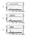
図4は、圧電素子から成るアクチュエータ151の駆動周波数と開口部211に圧力センサーを対向させ、噴射した流体のよどみ圧力波形を測定した結果を示すグラフである。
図4において、上段のグラフは、アクチュエータ(圧電素子)151の駆動波形で、図中左側の脈動した波形が出ている期間が脈動波群の駆動時間を示す。
また、図中、下段のグラフが、開口部211における流体のよどみ圧力波形を示す。
横軸は、経過時間(単位、秒)を示す。
Then, the result of having measured the ejection state of the fluid in the
FIG. 4 is a graph showing the result of measuring the stagnation pressure waveform of the ejected fluid with the driving frequency of the
In FIG. 4, the upper graph is a drive waveform of the actuator (piezoelectric element) 151, and a period in which a pulsating waveform on the left side in the figure is shown indicates the drive time of the pulsating wave group.
In the figure, the lower graph shows the stagnation pressure waveform of the fluid in the
The horizontal axis indicates the elapsed time (unit, second).
次に、流体噴射装置10の各部位の要件を説明する。接続流路Lの長さ150mm、開口部211の直径を0.2mm、ダイアフラム131の有効直径を6mm、イナータンス増加要素として直径を0.75mm、長さ12mmの出口流路を設定した。
アクチュエータ151の駆動周波数は、図4(a)が2.2kHz、図4(b)が3.7kHz、図4(c)が5kHzである。アクチュエータ151の駆動電圧は100Vとし、ON期間に6パルス出力している。
Next, the requirements of each part of the
The drive frequency of the
図4(a)では、流体の噴射によるよどみ圧力は、2気圧以下であるが安定している。
図4(b)では、よどみ圧力の最高値は2気圧を超えているが、その後不安定となる。
図5(c)では、最も高いよどみ圧力を示している。駆動周期2周期に1回のよどみ圧力の上昇が見られるのは、出口流路側流体制御要素としてイナータンス増加要素を用いているためで、イナータンス増加要素により、出口流路内での流動が駆動電圧1周期より長い間継続していることを示している。これは、効率よくポンプが流体を吐出していることを示し、また、この5kHzは接続流路内の流体の共鳴周波数にあたるため、相乗効果でよどみ圧力が上昇するのである。生体組織の切開能力はよどみ圧力と相関があるため本要件の流体噴射装置では、5kHzで駆動することが好ましい。
In FIG. 4A, the stagnation pressure due to fluid injection is 2 atm or less, but is stable.
In FIG. 4B, the maximum value of the stagnation pressure exceeds 2 atmospheres, but becomes unstable thereafter.
FIG. 5C shows the highest stagnation pressure. The stagnation pressure rises once every two drive cycles because the inertance increasing element is used as the outlet flow side fluid control element. The inertance increasing element causes the flow in the outlet flow to be driven by the driving voltage. It shows that it continues for longer than one cycle. This indicates that the pump is efficiently discharging the fluid, and since this 5 kHz corresponds to the resonance frequency of the fluid in the connecting flow path, the stagnation pressure rises due to a synergistic effect. Since the incision ability of the living tissue has a correlation with the stagnation pressure, it is preferable that the fluid ejecting apparatus of this requirement is driven at 5 kHz.
前述した条件で、実際に兎の肝臓を切開した実験結果を表1に示す。
表1は、アクチュエータ151の脈動波群の駆動時間と休止部の時間を変えて、肝臓組織の切開状態、出血量、切開時の気泡発生について実験したときの評価結果を示す。
アクチュエータ151の駆動周波数は5kHz、100Vで駆動とした。
なお、評価結果は、×は不可、△は許容できる範囲、○は良好、◎は最も良好というように表示している。
Table 1 shows the results of an experiment in which the liver of the vagina was actually incised under the conditions described above.
Table 1 shows the evaluation results when the incision state of the liver tissue, the amount of bleeding, and the generation of bubbles at the time of incision were tested while changing the driving time of the pulsating wave group of the
The driving frequency of the
The evaluation results are indicated such that × is not possible, Δ is an acceptable range, ○ is good, and ◎ is the best.

表1で示した実験結果から、脈動波群の駆動時間に対する休止部の時間(休止部の時間/脈動波群の駆動時間)が1〜5の範囲(実験番号3〜6)が許容できる範囲であり、また、休止部の時間が1msec〜10msecの範囲が許容できる範囲(実験番号3〜6)である。
休止部の時間1msecについてはデータがないが、実験番号7が0.4msecで不可評価のデータがあり、実験番号6が2msecで最もよい評価結果がでているので、1msecまでは許容できる範囲と推測した。
From the experimental results shown in Table 1, the range in which the time of the resting portion (the time of the resting portion / the driving time of the pulsating wave group) with respect to the driving time of the pulsating wave group is in the range of 1 to 5 (
There is no data for the pause time of 1 msec, but there is data that cannot be evaluated when experiment number 7 is 0.4 msec, and the best evaluation result is obtained when
従って、実施例1では、流体噴射装置10は、マイクロポンプ100のポンプ室132の容積を変更する手段を、圧電素子のアクチュエータ151とし、マイクロポンプ100によって流体は脈動状に流動されるが、接続流路管200が高剛性であるために、脈動による圧力波が開口部まで伝播し、切開能力が高く、気泡が発生しにくい脈動による流体の噴射が可能になっている。
Accordingly, in the first embodiment, the
また、マイクロポンプ100は、出口流路側に出口流路側流体制御要素としてイナータンス増加要素であるポンプ室体側出口流路301と接続管側出口流路302によって構成される出口流路が備えられているために、ポンプによる高圧の発生が可能である。
さらに、接続管側出口流路302と開口部211とは、接続流路201との接続部に流体の流動方向に段差の壁が形成されているので、前述の圧力波が接続流路201内のこの壁の間でより効率よく反射され、適当な駆動周波数時には共鳴によって圧力を高めることができる。また、出口流路側の壁は、逆止弁よりも構造的強度が高いため破壊される心配がないという効果もある。
Further, the
Further, since the connection pipe side
この流体噴射装置10は、生体の臓器の手術用メスとして用いられる。この際、生体内部臓器の組織切開をする場合、生体の内部の処置部近傍まで開口部211が達していることが求められるが、接続流路201(図中、L)が100mm〜200mmに設定されているために、例えば、肝臓や脳神経領域の手術や、他の臓器等の切開を行うには充分の長さであり、また、術野の視界を妨げない適当な長さであり、さらに、施術者が、この流体噴射装置10を正確に扱える好適な長さである。
本発明では、接続流路の長さは、100mm以下でも、200mm以上でもマイクロポンプの適切な設定で要求される性能の流体噴射装置が得られるが、先述の理由から100mm〜200mmの範囲が最も好ましい。
This
In the present invention, although the length of the connection flow path is 100 mm or less or 200 mm or more, a fluid ejecting apparatus having the performance required by the appropriate setting of the micropump can be obtained, but the range of 100 mm to 200 mm is the most for the reason described above. preferable.
実施例1の流体噴射装置10は、接続流路201の直径が1mm〜3mmで、接続流路管200の外殻の厚さが0.1mm〜1mmの範囲で設定されているので、接続流路管200の外殻直径は最大5mmとなる。これは、前述した接続流路201の長さの範囲と同様、臓器の手術の際に、処置部周辺に接続流路管201が接触しない範囲で適切な太ささであるが、好ましくは、2mm〜4mmの範囲に設定される。
In the
また、実施例1では、接続流路管200の開口部にノズル210が備えられているので、例えば、処置部に合わせた形状を自在に選択することができる他、例えば、直径が縮小されている開口部211に流体導入部212を設けることで噴射された流体が分散することなく所定の部位に正確に集中流を噴射させることができるという効果もある。
なお、ノズル210は、接続流路管200に圧入しているが、ノズル210と接続流路管200に螺子を螺設して螺合固定すれば、処置部の部位によって適当なノズルを選択して使用することが容易に行うことができる。
Moreover, in Example 1, since the
The
さらに、実施例1では、接続流路の長さL、流体の音速Q、ポンプ容積の変更周波数(圧電素子の駆動周波数)fとの関係をn・2L=Q/fもしくは2L/n=Q/fにしているため、アクチュエータ151(圧電素子)の駆動周波数に流体の圧力波の反射が共鳴関係にあり、接続流路内の流体の圧力がより高くなり、効率よく流体が高速で噴射されるので、生体組織の切開能力が高められるという効果がある。 Furthermore, in Example 1, the relationship between the length L of the connection flow path, the sound velocity Q of the fluid, and the pump volume change frequency (piezoelectric element drive frequency) f is n · 2L = Q / f or 2L / n = Q. Therefore, the reflection of the pressure wave of the fluid is in resonance with the drive frequency of the actuator 151 (piezoelectric element), the pressure of the fluid in the connection flow path becomes higher, and the fluid is efficiently ejected at high speed. Therefore, there is an effect that the incision ability of the living tissue is enhanced.
また、実施例1の流体噴射装置10では、流体が脈動波群と休止部との繰り返しで流動される。前述したように、脈動波群による駆動時と休止部との繰り返しの際の脈動によるよどみ圧力により切開能力も高くなるため、連続流の切開に比べ切開能力を高めることができる。しかも、脈動による切開は流体量が少なくなるため、術野に溜まる流体による気泡の発生も少なくなると言う効果がある。
Further, in the
また、脈動波群の駆動時間に対する休止部の時間が1〜5、休止部の時間が1msec〜10msecの範囲で設定されているために、噴射流体の切開能力を高めることができるが、脈動波群の駆動時間との間隔を適切に設定することができる。このことから、処置部の切開時に、流体が生体組織に当たった際に発生する気泡をさらに減ずるとともに、休止部の時間を設けることで残存気泡を減ずることができる。従って、気泡が術野の視野を妨げるというような問題を防止することができる。 Moreover, since the time of the rest part with respect to the driving time of the pulsating wave group is set in the range of 1 to 5 and the time of the rest part is set in the range of 1 msec to 10 msec, the incision ability of the jet fluid can be enhanced. The interval with the driving time of the group can be set appropriately. From this, at the time of incision of the treatment portion, the bubbles generated when the fluid hits the living tissue can be further reduced, and the remaining bubbles can be reduced by providing a time for the resting portion. Therefore, it is possible to prevent the problem that the bubbles obstruct the visual field of the operative field.
図5は、本発明の実施例2の流体噴射装置10を示す。実施例2は、実施例1で示した出口流路管300と接続流路管200とノズル210を一体で成形したところに特徴があり、それ以外のマイクロポンプ100の構造及び流体噴射装置の駆動方法は実施例1(図1〜図4、参照)と同じであり、実験結果もほぼ同等な評価が得られている。従って、相違個所のみを説明する。なお、実施例1(図1、参照)と同じ機能部分は、同じ符号を付与している。
FIG. 5 shows a
図5は、実施例2の流体噴射装置10の縦断面を示す。図5において、接続流路管200は、一方の端部が、ポンプ室体130の側面に突出された接続流路管固定部134に圧入されて、出口流路301とポンプ室132が流通される。接続流路管200の開口部211に向かって、流路の直径が変化している位置までが出口流路301とされ、そこから開口部211までが接続流路201とされる。
FIG. 5 shows a longitudinal section of the
接続流路201と出口流路301の直径は、接続流路側が大きい。接続流路管200の先端は、細く絞り込まれた形状で、流体の入口側に流体導入部212を有する開口部211が設けられている。なお、開口部外側は、なだらかに丸められている。
ここで、出口流路301との境から開口部211の流体入口までを接続流路とし、その長さLが100mm〜200mmの範囲に設定されている。
なお、接続流路管200は、実施例1と同程度の剛性を有している。
The diameters of the
Here, the connection channel is from the boundary with the
The connection
また、接続流路201の直径が1mm〜3mmで、接続流路管200の外殻の厚さが0.1mm〜1mmの範囲で設定され、実施例1と同様に、接続流路の長さL、流体の音速Q、ポンプ容積の変更周波数(圧電素子の駆動周波数)fとの関係をn・2L=Q/fもしくは2L/n=Q/fと成るようにポンプ容積の変更周波数fが設定されている。
Further, the diameter of the
従って、実施例2では、実施例1で示した出口流路管300と接続流路管200とノズル210とが一体で形成されていることが実施例1と異なるだけのため、前述した実施例1と同様な効果が得られる。
また、接続流路管200は、金属製のパイプの先端部を絞り込みのような加工手段で開口部211を形成することができるので、構造が簡単でコストを低減することができる。
Therefore, the second embodiment differs from the first embodiment in that the
Further, the
図6は、本発明の実施例3の流体噴射装置が示されている。実施例3は、入口流路側と出口流路側に流体抵抗要素としての逆止弁を備えた構造で、実施例1、実施例2の技術思想をそのままに他の構造の流体噴射装置を提供するものである。なお、実施例1(図1、参照)及び実施例2(図5、参照)と同じ機能部分は、同じ符号を付与している。
図6は、実施例3の流体噴射装置の縦断面図を示す。図6において、流体噴射装置10は、入口流路122と接続流路201とポンプ室132を備えるポンプ室体130と、アクチュエータ151とアクチュエータ151が固着された筐体152を備えるアクチュエータユニット150とから構成されている。
FIG. 6 shows a fluid ejecting apparatus according to
FIG. 6 is a longitudinal sectional view of the fluid ejecting apparatus according to the third embodiment. In FIG. 6, the
入口流路122のポンプ室132との接続部のポンプ室132側には、入口流路逆止弁141が備えられており、この入口流路逆止弁141はポンプ室132側に開放される。入口流路122の他方の端部は、図示しないタンクなどに流通するチューブ143に接続されている。なお、接続流路122は、ポンプ室132に流通する手前で、図中約90度に曲げられているが、この角度や方向は特に制約されるものではなく、流体抵抗を増加しない範囲の曲率であれば、性能には影響しない。
接続流路201側にも接続流路逆止弁142が備えられている。
An inlet
A connection flow
接続流路逆止弁142は、アクチュエータ151に対して入口流路逆止弁141と略同じ距離に設けられている。この接続流路逆止弁142は、接続流路201側に開放される。接続流路201は、ポンプ室体130から突出されたパイプ状の接続流路管200に穿接され、先端部にはノズル210が圧入されている。本実施例3では、前述した実施例1で示した接続流路管200と出口流路接続管300とポンプ室体130が一体に構成されたもので、その機能は実施例1と同じである。
The connection flow
ポンプ室体130のアクチュエータユニット150側にはダイアフラム131が密着固定され、このダイアフラム131とポンプ室体130とから構成される空間がポンプ室132である。
A
アクチュエータユニット150は、一方が開口された筐体152の内側端面に圧電素子からなるアクチュエータ151の一方の端面が固着されており、筐体152の開口部周縁がダイアフラム131に固着されている。この際、アクチュエータ151の他方の端面がダイアフラム131に密接される。
In the
ここで、アクチュエータユニット150とポンプ室体130(接続流路201を除く)とをマイクロポンプと称する。このマイクロポンプの駆動動作は、実施例1で示したものと同じであるが、二つの逆止弁141,142を備える点が異なるため、この逆止弁141,142の動作について説明する。
Here, the
アクチュエータ(圧電素子)151が収縮すると、ポンプ室132の容積を増加させ、入口流路逆止弁141が開放され流体がポンプ室132内に流入し、接続流路逆止弁142は密閉され流体の流出は停止する。また、アクチュエータ151が伸張すると、ポンプ室体132の容積が減少し、入口流路逆止弁141が密閉され、接続流路逆止弁142が開放されて流体が流出する。
When the actuator (piezoelectric element) 151 contracts, the volume of the
ここで、接続流路201及び接続流路管200の要件について説明する。
出口流路側流体制御要素としての接続流路逆止弁142とノズル210の開口部211の入口側との間の接続流路の長さLを100mm〜200mm、接続流路201の直径を1mm〜3mmで、接続流路管200の外殻の厚さを0.1mm〜1mmの範囲で設定する。
Here, the requirements of the
The length L of the connection channel between the connection
また、流体噴射装置10の駆動方法としては、接続流路内の流体の音速をQとし、前述した接続流路の長さをL、ポンプ室容積の変更周波数をf、nを正の整数としたとき、n・2L=Q/fもしくは2L/n=Q/fを満たすようにポンプ室容積の変更を行う。
Further, as a driving method of the
本実施例3の流体噴射装置10も実施例1と同様に脈動波群と休止部との繰り返しで流動されるが、脈動波群の駆動時間に対する休止部の時間が1〜5、且つ、脈動波群と休止部との繰り返しの休止部の時間が1msec〜10msecの範囲の組み合わせで駆動される。
Similarly to the first embodiment, the
従って、実施例3では、流体抵抗要素としての逆止弁が二つ備えられているが、流体噴射に係わる要件は、実施例1と同じに設定されるため、得られる効果も同等である。
なお、一般のマイクロポンプは、実施例3のようにポンプ室の流入側及び流出側に逆止弁を備えることか多いが、このようなマイクロポンプにも、前述した本実施例の要件を満たせば、同様な効果を得ることができる。
Accordingly, in the third embodiment, two check valves are provided as fluid resistance elements. However, since the requirements related to the fluid ejection are set to be the same as those in the first embodiment, the obtained effects are equivalent.
It should be noted that a general micropump is often provided with check valves on the inflow side and the outflow side of the pump chamber as in the third embodiment, but such a micropump can also satisfy the above-described requirements of the present embodiment. In this case, the same effect can be obtained.
図7〜図9は、本発明の実施例4のカバー付き流体噴射装置11が示されている。実施例4は、実施例1〜実施例3で示された流体噴射装置に手で握って操作がし易いカバーを備えていることが特徴である。なお、図7〜図9では、実施例1及び実施例2に記載の流体噴射装置を例に示しているが、実施例3の流体噴射装置にも応用できることはいうまでもない。
図7は、実施例4のカバー付き流体噴射装置11の縦断面図、図8はカバー160の縦断面図、図9は、図7で示されたカバー付き流体噴射装置11の平面図である。図7、図8において、流体噴射装置10は、カバー160によってマイクロポンプ100と、接続流路管200及び入口接続管121に接続されるチューブ143の一部の周囲を覆われている。
7 to 9 show a
7 is a longitudinal sectional view of the
カバー160は、図8中、A−Aで示された位置で上カバー165、下カバー166に2分割されている。上カバー165、下カバー166が合わせられた状態で、マイクロポンプ100の本体部分が入る空間161、出口流路管300が入る空間162が構成されている。
図7に示すように、流体噴射装置10は、カバー160で覆われるが、マイクロポンプ100は、カバー160とは接触しないように空間が設けられている。
In FIG. 8, the
As shown in FIG. 7, the
カバー160は、チューブ143と接続流路管200をカバー165,166で鋏み込んで押圧固定するが、カバー160の内部空間は、外気とは密閉状態にされる。従って、チューブ143側の固定部167と接続流路管200側の固定部168は、それぞれチューブ外径、接続流路管200の外径と同じか、小さい直径の孔とし、圧接状態にする。
特に接続流路管側の固定部168には、パイプ状のシール部材169を挿着することで、密閉性が高められる。
The
In particular, the sealing performance is enhanced by inserting a pipe-shaped
図9において、上カバー165、下カバー166(図示せず)は、チューブ143近傍と接続流路管200近傍において、螺子170によって、上下螺合固定される。この際、螺子170の螺子頭は、カバー内に埋没するように座グリ穴171が設けられている。
なお、カバー160の材質としては、握っても変形しない程度の剛性があり、振動吸収性が高く、また断熱性が高い材料が選択されるが、シリコン系ゴム、ウレタン系ゴムや、硬度が低い他の剛性樹脂等を採用することができる。しかし、カバー160を握ったときに変形しない程度の剛性を有する。
In FIG. 9, the
As a material for the
本発明の流体噴射装置は、手で握って操作される。従って、本実施例4では、前述したように、流体噴射装置10が圧電素子で駆動されるので、圧電素子の振動にマイクロポンプ100を構成する筐体152等が共振して、その振動が手に伝達されることが考えられる。従って、カバー160が振動吸収材で構成されることで、マイクロポンプ100の振動を吸収できるので,振動が手に伝わることがなく微細な部位の施術を行い易いうえ、施術者の疲労を減ずるという効果もある。
The fluid ejecting apparatus of the present invention is operated by grasping with a hand. Therefore, in the fourth embodiment, as described above, since the
また、このカバーは着脱が自在であるために、流体噴射装置からカバーを外して洗浄することができ、さらに、マイクロポンプはそのままに、処置部によって異なった形状のカバーを用意して交換して使用すれば、操作性をより一層高めることができる。 In addition, since this cover is detachable, it can be cleaned by removing the cover from the fluid ejecting device. If used, the operability can be further enhanced.
さらに、この流体噴射装置10は、長時間にわたって使用されることが想定され、施術者の体温によって流体の温度が上昇することが考えられるので、カバーが断熱材で形成されているため、手の温度が伝達しにくいという効果がある。
また、流体噴射装置10がカバー160で覆われているために、噴射された流体や、生体組織切開時に血液等がマイクロポンプ100に付着することを防止することができる。
Further, the
Further, since the
なお、本発明は前述の実施例に限定されるものではなく、本発明の目的を達成できる範囲での変形、改良等は本発明に含まれるものである。
例えば、前述の実施例では、流体噴射装置は、生体組織の切開を例にあげ説明したが、その他に、結石等の破砕や、生体細胞に液体を導入したり、血管内塞栓の除去等にも応用できる。
さらに、医療分野以外でも、前述の噴流を動力源とする動力装置や冷却装置に応用することができる。
In addition, this invention is not limited to the above-mentioned Example, The deformation | transformation in the range which can achieve the objective of this invention, improvement, etc. are included in this invention.
For example, in the above-described embodiments, the fluid ejecting apparatus has been described by taking an incision of a living tissue as an example. In addition, the fluid ejecting apparatus is used for crushing stones, introducing a liquid into living cells, removing an intravascular embolus, and the like. Can also be applied.
Furthermore, the present invention can be applied to a power device and a cooling device using the above-described jet flow as a power source even outside the medical field.
従って、前述の実施例1〜実施例4では、生体組織の切開能力を高め、血管等の脈管組織を保存しながら病変組織部のみを切開することができ、また、気泡の発生、残存を減じて術野の視野を確保する流体噴射装置と、その駆動方法を提供することができる。 Therefore, in the above-described Examples 1 to 4, it is possible to enhance the incision ability of living tissue, incision can be made only on the lesioned tissue part while preserving vascular tissue such as blood vessels, etc. It is possible to provide a fluid ejecting apparatus that reduces the field of view of the surgical field and a driving method thereof.
10…流体噴射装置、100…マイクロポンプ、132…ポンプ室、160…カバー、200…接続流路管、201…接続流路、211…開口部、301…ポンプ室体側出口流路、302…接続流側出口流路。
DESCRIPTION OF
Claims (14)
前記マイクロポンプの出口流路に一方の端部が接続され、他方の端部が前記出口流路の直径よりも縮小された開口部が設けられた接続流路と、
前記接続流路が穿設され、前記マイクロポンプから流動される前記流体の脈動を前記開口部に伝達し得る剛性を有する接続流路管と、
が、備えられ、
前記マイクロポンプが、前記流体が流入される入口流路室を構成する入口流路体と、前記入口流路体と別部材で構成され、前記入口流路室と連通する前記ポンプ室を構成するポンプ室体と、前記入口流路室と前記ポンプ室との境界部に設けられ、前記ポンプ室から前記入口流路室への前記流体の流入を抑制する逆止弁と、を備えるとともに、前記接続流路の前記出口流路側に流体抵抗要素またはイナータンス増加要素を出口流路側流体制御要素として備え、
前記接続流路の直径が前記イナータンス増加要素の直径よりも大きいことを特徴とする流体噴射装置。 A micropump comprising a pump chamber, and performing a fluid discharge operation by changing the volume of the pump chamber;
One end is connected to the outlet channel of the micropump, and the other end is provided with an opening that is smaller than the diameter of the outlet channel.
The connection flow path pipe having the rigidity capable of transmitting the pulsation of the fluid flowing from the micropump to the opening, the connection flow path being perforated;
Is provided,
The micropump is composed of an inlet channel body that constitutes an inlet channel chamber into which the fluid flows, and a member separate from the inlet channel body, and constitutes the pump chamber that communicates with the inlet channel chamber Rutotomoni comprising pump chamber and body, provided at a boundary portion between the pump chamber and the inlet flow passage chamber, and a check valve inhibits the flow of the fluid into the inlet flow passage chamber from the pump chamber, A fluid resistance element or an inertance increasing element is provided as an outlet channel side fluid control element on the outlet channel side of the connection channel,
The fluid ejecting apparatus according to claim 1, wherein a diameter of the connection channel is larger than a diameter of the inertance increasing element .
前記入口流路体と前記ポンプ室体との接合部に、Oリングが収容されるための空間が設けられ、前記空間の内部にOリングが装着された状態で、前記入口流路体と前記ポンプ室体とが接合されていることを特徴とする流体噴射装置。 The fluid ejection device according to claim 1,
A space for accommodating an O-ring is provided at a joint between the inlet channel body and the pump chamber body, and the O-ring is attached to the inside of the space. A fluid ejecting apparatus, wherein the pump chamber body is joined.
前記出口流路側流体制御要素と前記開口部との間の接続流路の長さが100mm〜200mmであることを特徴とする流体噴射装置。 The fluid ejection device according to claim 1 ,
The fluid ejection device according to claim 1, wherein a length of a connection channel between the outlet channel side fluid control element and the opening is 100 mm to 200 mm.
前記開口部側から前記出口流路側へ伝搬してきた前記流体の圧力波を反射させる壁部を有することを特徴とする流体噴射装置。 The fluid ejection device according to claim 1 ,
A fluid ejecting apparatus which is characterized in that have a wall portion that reflects pressure waves of the fluid has been propagated to the outlet flow path from the opening side.
前記接続流路内の流体の音速をQとし、前記出口流路側流体制御要素と前記開口部との間の接続流路の長さをL、ポンプ室容積の変更周波数をf、nを正の整数としたとき、n・2L=Q/fもしくは2L/n=Q/fを満たすように前記ポンプ室容積の変更を行うことを特徴とした流体噴射装置。 The fluid ejection device according to claim 4 , wherein
The sound speed of the fluid in the connecting flow path and is Q, the length of the connecting channel between the opening and said outlet passage side fluid control element L, and changes the frequency of the pump chamber volume f, n a positive The fluid ejecting apparatus is characterized in that, when an integer is used, the pump chamber volume is changed so as to satisfy n · 2L = Q / f or 2L / n = Q / f.
前記接続流路の直径が1mm〜3mmで、前記接続流路管の外殻の厚さが0.1mm〜1mmであることを特徴とする流体噴射装置。 The fluid ejection device according to any one of claims 1 to 5 ,
The fluid ejecting apparatus according to claim 1, wherein a diameter of the connection channel is 1 mm to 3 mm, and a thickness of an outer shell of the connection channel pipe is 0.1 mm to 1 mm.
前記接続流路の先端にノズルが備えられていることを特徴とする流体噴射装置。 The fluid ejection device according to any one of claims 1 to 6 ,
A fluid ejecting apparatus comprising a nozzle at a tip of the connection flow path.
前記流体が脈動波群と休止部との繰り返しで流動されることを特徴とする流体噴射装置。 The fluid ejection device according to any one of claims 1 to 7 ,
The fluid ejecting apparatus, wherein the fluid is caused to flow by repetition of a pulsating wave group and a resting portion.
前記脈動波群の駆動時間に対する前記休止部の時間が1〜5であることを特徴とする流体噴射装置。 The fluid ejection device according to claim 8 , wherein
The fluid ejecting apparatus according to claim 1, wherein a time of the pause portion is 1 to 5 with respect to a driving time of the pulsating wave group.
前記休止部の時間が1msec〜10msecであることを特徴とする流体噴射装置。 The fluid ejection device according to claim 8 or 9 , wherein
The fluid ejecting apparatus according to claim 1, wherein a time of the resting part is 1 msec to 10 msec.
前記マイクロポンプに、着脱自在のカバーが装着されていることを特徴とする流体噴射装置。 The fluid ejection device according to any one of claims 1 to 10 ,
A fluid ejecting apparatus, wherein a removable cover is attached to the micropump.
前記カバーが、振動吸収材または断熱材で形成されていることを特徴とする流体噴射装置。 The fluid ejection device according to claim 11 , wherein
The fluid ejecting apparatus, wherein the cover is formed of a vibration absorbing material or a heat insulating material.
前記接続流路と前記ポンプ室との境界部に、前記接続流路から前記ポンプ室への前記流体の流入を抑制する接続流路逆止弁を備えたことを特徴とする流体噴射装置。 The fluid ejection device according to any one of claims 1 to 12 ,
A fluid ejecting apparatus comprising a connection channel check valve that suppresses inflow of the fluid from the connection channel to the pump chamber at a boundary between the connection channel and the pump chamber.
前記接続流路管の先端に、前記開口部を有するノズルが螺合されていることを特徴とする流体噴射装置。 The fluid ejection device according to any one of claims 1 to 13 ,
A fluid ejecting apparatus, wherein a nozzle having the opening is screwed into a distal end of the connection flow channel pipe.
Priority Applications (1)
| Application Number | Priority Date | Filing Date | Title |
|---|---|---|---|
| JP2008270031A JP4778545B2 (en) | 2008-10-20 | 2008-10-20 | Fluid ejection device |
Applications Claiming Priority (1)
| Application Number | Priority Date | Filing Date | Title |
|---|---|---|---|
| JP2008270031A JP4778545B2 (en) | 2008-10-20 | 2008-10-20 | Fluid ejection device |
Related Parent Applications (1)
| Application Number | Title | Priority Date | Filing Date |
|---|---|---|---|
| JP2003392633A Division JP4266788B2 (en) | 2003-11-21 | 2003-11-21 | Fluid ejection device |
Publications (2)
| Publication Number | Publication Date |
|---|---|
| JP2009056320A JP2009056320A (en) | 2009-03-19 |
| JP4778545B2 true JP4778545B2 (en) | 2011-09-21 |
Family
ID=40552576
Family Applications (1)
| Application Number | Title | Priority Date | Filing Date |
|---|---|---|---|
| JP2008270031A Expired - Lifetime JP4778545B2 (en) | 2008-10-20 | 2008-10-20 | Fluid ejection device |
Country Status (1)
| Country | Link |
|---|---|
| JP (1) | JP4778545B2 (en) |
Families Citing this family (20)
| Publication number | Priority date | Publication date | Assignee | Title |
|---|---|---|---|---|
| JP4788809B2 (en) * | 2009-08-17 | 2011-10-05 | セイコーエプソン株式会社 | Fluid injection method |
| JP5540760B2 (en) * | 2010-02-22 | 2014-07-02 | セイコーエプソン株式会社 | Liquid ejector |
| JP6229286B2 (en) | 2013-03-29 | 2017-11-15 | セイコーエプソン株式会社 | Liquid ejector, medical equipment |
| JP2015196025A (en) * | 2014-04-03 | 2015-11-09 | セイコーエプソン株式会社 | Liquid injection device and medical equipment |
| KR101905830B1 (en) | 2016-11-15 | 2018-10-08 | 울산과학기술원 | Cryoanesthesia device, method for controlling cryoanesthesia device and temperature controller of coolant in cryoanesthesia device |
| WO2018221848A1 (en) | 2017-05-30 | 2018-12-06 | 주식회사 리센스메디컬 | Medical cooling device |
| KR20180131352A (en) | 2017-05-30 | 2018-12-10 | 주식회사 리센스메디컬 | Medical cooling apparatus |
| KR102517065B1 (en) | 2017-12-29 | 2023-04-03 | 주식회사 리센스메디컬 | Cooling generator |
| EP3785682B1 (en) | 2018-04-27 | 2023-01-18 | Recensmedical, Inc. | Cooling apparatus and cooling method |
| KR102170327B1 (en) * | 2018-04-27 | 2020-10-26 | 주식회사 리센스메디컬 | Medical cooling device |
| US11666479B2 (en) | 2018-08-19 | 2023-06-06 | Recensmedical, Inc. | Device for cooling anesthesia by chilled fluidic cooling medium |
| USD921911S1 (en) | 2019-06-21 | 2021-06-08 | Recensmedical, Inc. | Medical cooling device |
| USD921211S1 (en) | 2019-06-21 | 2021-06-01 | Recensmedical, Inc. | Medical cooling device |
| US11278341B2 (en) | 2020-07-14 | 2022-03-22 | Recensmedical, Inc. | Method of safely using controlled cooling systems and devices |
| USD968626S1 (en) | 2020-08-07 | 2022-11-01 | Recensmedical, Inc. | Medical cooling device |
| USD968627S1 (en) | 2020-08-07 | 2022-11-01 | Recensmedical, Inc. | Medical cooling device |
| USD977633S1 (en) | 2020-08-07 | 2023-02-07 | Recensmedical, Inc. | Cradle for a medical cooling device |
| KR102226322B1 (en) * | 2020-10-20 | 2021-03-10 | 주식회사 리센스메디컬 | Medical cooling device |
| KR102289913B1 (en) * | 2020-10-20 | 2021-08-13 | 주식회사 리센스메디컬 | Medical cooling device |
| KR102533817B1 (en) * | 2021-03-04 | 2023-05-18 | 주식회사 리센스메디컬 | Medical cooling device |
Family Cites Families (5)
| Publication number | Priority date | Publication date | Assignee | Title |
|---|---|---|---|---|
| JPH05312153A (en) * | 1992-05-13 | 1993-11-22 | Seiko Epson Corp | Micropump and manufacture thereof |
| CA2127637C (en) * | 1993-07-26 | 2006-01-03 | Scott Bair | Fluid jet surgical cutting tool |
| US6117150A (en) * | 1997-07-14 | 2000-09-12 | Cook Urological Incorporated | Pneumatic tissue dissector with exhaust system |
| JP2002130137A (en) * | 2000-10-30 | 2002-05-09 | Ckd Corp | Piezoelectric pump |
| JP2002322986A (en) * | 2001-02-21 | 2002-11-08 | Seiko Epson Corp | Pump |
-
2008
- 2008-10-20 JP JP2008270031A patent/JP4778545B2/en not_active Expired - Lifetime
Also Published As
| Publication number | Publication date |
|---|---|
| JP2009056320A (en) | 2009-03-19 |
Similar Documents
| Publication | Publication Date | Title |
|---|---|---|
| JP4778545B2 (en) | Fluid ejection device | |
| JP4266788B2 (en) | Fluid ejection device | |
| JP4311483B2 (en) | Liquid ejecting apparatus and surgical instrument using the same | |
| JP4666094B2 (en) | PULSE FLOW GENERATION DEVICE, MEDICAL DEVICE, AND METHOD OF CONTROLLING PULSE FLOW GENERATION DEVICE | |
| US9730723B2 (en) | Fluid injection device | |
| JP5585369B2 (en) | Fluid ejecting apparatus and medical device | |
| JP2010051430A (en) | Pulse generating mechanism, connection flow channel tube, fluid ejection apparatus | |
| JP2010106748A (en) | Fluid ejection system, method for driving fluid ejection system, and surgical apparatus | |
| US20100082054A1 (en) | Fluid ejection device and fluid ejection method | |
| EP2491875A2 (en) | Fluid ejection device | |
| JP2014188240A (en) | Fluid jetting device, and medical equipment | |
| JP5320906B2 (en) | Fluid ejection surgical instrument and fluid ejection method | |
| JP2009285116A (en) | Fluid jetting device, method for driving fluid jetting device and surgical apparatus | |
| JP2010059939A (en) | Fluid injection device, method of controlling fluid injection device, and surgical device | |
| JP5879904B2 (en) | Channel pipe and fluid ejection device | |
| JP5782763B2 (en) | Fluid ejection device | |
| JP2010077949A (en) | Fluid injection device, method for molding pipe member, fluid injection unit, and surgical apparatus | |
| JP2009108866A (en) | Fluid jet device | |
| JP2010051517A (en) | Fluid injection device, fluid injection surgical implement, and fluid injection method | |
| JP2011024706A (en) | Method for driving fluid ejection device | |
| EP2649954A1 (en) | Ultrasonic wave processing device | |
| JP5509766B2 (en) | Fluid ejection device and treatment device | |
| JP5167792B2 (en) | Medical equipment | |
| JP2011017342A (en) | Pulsating flow generating apparatus, medical equipment and method of controlling the pulsating flow generating apparatus | |
| JP6003951B2 (en) | Fluid ejection unit and medical device |
Legal Events
| Date | Code | Title | Description |
|---|---|---|---|
| A521 | Request for written amendment filed |
Free format text: JAPANESE INTERMEDIATE CODE: A523 Effective date: 20081212 |
|
| A131 | Notification of reasons for refusal |
Free format text: JAPANESE INTERMEDIATE CODE: A131 Effective date: 20110301 |
|
| A521 | Request for written amendment filed |
Free format text: JAPANESE INTERMEDIATE CODE: A523 Effective date: 20110427 |
|
| A521 | Request for written amendment filed |
Free format text: JAPANESE INTERMEDIATE CODE: A821 Effective date: 20110428 |
|
| TRDD | Decision of grant or rejection written | ||
| A01 | Written decision to grant a patent or to grant a registration (utility model) |
Free format text: JAPANESE INTERMEDIATE CODE: A01 Effective date: 20110607 |
|
| A01 | Written decision to grant a patent or to grant a registration (utility model) |
Free format text: JAPANESE INTERMEDIATE CODE: A01 |
|
| A61 | First payment of annual fees (during grant procedure) |
Free format text: JAPANESE INTERMEDIATE CODE: A61 Effective date: 20110701 |
|
| R150 | Certificate of patent or registration of utility model |
Free format text: JAPANESE INTERMEDIATE CODE: R150 Ref document number: 4778545 Country of ref document: JP Free format text: JAPANESE INTERMEDIATE CODE: R150 |
|
| FPAY | Renewal fee payment (event date is renewal date of database) |
Free format text: PAYMENT UNTIL: 20140708 Year of fee payment: 3 |
|
| R250 | Receipt of annual fees |
Free format text: JAPANESE INTERMEDIATE CODE: R250 |
|
| R250 | Receipt of annual fees |
Free format text: JAPANESE INTERMEDIATE CODE: R250 |
|
| S531 | Written request for registration of change of domicile |
Free format text: JAPANESE INTERMEDIATE CODE: R313531 |
|
| R350 | Written notification of registration of transfer |
Free format text: JAPANESE INTERMEDIATE CODE: R350 |
|
| R250 | Receipt of annual fees |
Free format text: JAPANESE INTERMEDIATE CODE: R250 |
|
| R250 | Receipt of annual fees |
Free format text: JAPANESE INTERMEDIATE CODE: R250 |
|
| R250 | Receipt of annual fees |
Free format text: JAPANESE INTERMEDIATE CODE: R250 |
|
| R250 | Receipt of annual fees |
Free format text: JAPANESE INTERMEDIATE CODE: R250 |
|
| R250 | Receipt of annual fees |
Free format text: JAPANESE INTERMEDIATE CODE: R250 |
|
| R250 | Receipt of annual fees |
Free format text: JAPANESE INTERMEDIATE CODE: R250 |
|
| R250 | Receipt of annual fees |
Free format text: JAPANESE INTERMEDIATE CODE: R250 |
|
| R250 | Receipt of annual fees |
Free format text: JAPANESE INTERMEDIATE CODE: R250 |
|
| EXPY | Cancellation because of completion of term |