EP2649954A1 - Ultrasonic wave processing device - Google Patents
Ultrasonic wave processing device Download PDFInfo
- Publication number
- EP2649954A1 EP2649954A1 EP12828468.4A EP12828468A EP2649954A1 EP 2649954 A1 EP2649954 A1 EP 2649954A1 EP 12828468 A EP12828468 A EP 12828468A EP 2649954 A1 EP2649954 A1 EP 2649954A1
- Authority
- EP
- European Patent Office
- Prior art keywords
- opening
- probe
- sheath
- suction
- suction port
- Prior art date
- Legal status (The legal status is an assumption and is not a legal conclusion. Google has not performed a legal analysis and makes no representation as to the accuracy of the status listed.)
- Granted
Links
- 239000000523 sample Substances 0.000 claims abstract description 153
- 230000002093 peripheral effect Effects 0.000 claims abstract description 89
- 238000009210 therapy by ultrasound Methods 0.000 claims abstract description 42
- 239000007788 liquid Substances 0.000 claims description 72
- 230000002265 prevention Effects 0.000 claims description 18
- 230000004048 modification Effects 0.000 description 26
- 238000012986 modification Methods 0.000 description 26
- 230000000052 comparative effect Effects 0.000 description 9
- 210000003494 hepatocyte Anatomy 0.000 description 3
- 239000002504 physiological saline solution Substances 0.000 description 3
- 210000004204 blood vessel Anatomy 0.000 description 2
- 230000008878 coupling Effects 0.000 description 2
- 238000010168 coupling process Methods 0.000 description 2
- 238000005859 coupling reaction Methods 0.000 description 2
- 230000006866 deterioration Effects 0.000 description 2
- 230000000694 effects Effects 0.000 description 2
- 230000000740 bleeding effect Effects 0.000 description 1
- 238000012790 confirmation Methods 0.000 description 1
- 230000008034 disappearance Effects 0.000 description 1
- 229920006395 saturated elastomer Polymers 0.000 description 1
- 239000000243 solution Substances 0.000 description 1
- 238000001356 surgical procedure Methods 0.000 description 1
- 238000005406 washing Methods 0.000 description 1
- XLYOFNOQVPJJNP-UHFFFAOYSA-N water Substances O XLYOFNOQVPJJNP-UHFFFAOYSA-N 0.000 description 1
Images


Classifications
-
- A—HUMAN NECESSITIES
- A61—MEDICAL OR VETERINARY SCIENCE; HYGIENE
- A61B—DIAGNOSIS; SURGERY; IDENTIFICATION
- A61B17/00—Surgical instruments, devices or methods, e.g. tourniquets
- A61B17/32—Surgical cutting instruments
- A61B17/320068—Surgical cutting instruments using mechanical vibrations, e.g. ultrasonic
-
- A—HUMAN NECESSITIES
- A61—MEDICAL OR VETERINARY SCIENCE; HYGIENE
- A61B—DIAGNOSIS; SURGERY; IDENTIFICATION
- A61B17/00—Surgical instruments, devices or methods, e.g. tourniquets
- A61B17/22—Implements for squeezing-off ulcers or the like on the inside of inner organs of the body; Implements for scraping-out cavities of body organs, e.g. bones; Calculus removers; Calculus smashing apparatus; Apparatus for removing obstructions in blood vessels, not otherwise provided for
- A61B17/22004—Implements for squeezing-off ulcers or the like on the inside of inner organs of the body; Implements for scraping-out cavities of body organs, e.g. bones; Calculus removers; Calculus smashing apparatus; Apparatus for removing obstructions in blood vessels, not otherwise provided for using mechanical vibrations, e.g. ultrasonic shock waves
- A61B2017/22005—Effects, e.g. on tissue
- A61B2017/22007—Cavitation or pseudocavitation, i.e. creation of gas bubbles generating a secondary shock wave when collapsing
- A61B2017/22008—Cavitation or pseudocavitation, i.e. creation of gas bubbles generating a secondary shock wave when collapsing used or promoted
-
- A—HUMAN NECESSITIES
- A61—MEDICAL OR VETERINARY SCIENCE; HYGIENE
- A61B—DIAGNOSIS; SURGERY; IDENTIFICATION
- A61B17/00—Surgical instruments, devices or methods, e.g. tourniquets
- A61B17/32—Surgical cutting instruments
- A61B17/320068—Surgical cutting instruments using mechanical vibrations, e.g. ultrasonic
- A61B2017/32007—Surgical cutting instruments using mechanical vibrations, e.g. ultrasonic with suction or vacuum means
-
- A—HUMAN NECESSITIES
- A61—MEDICAL OR VETERINARY SCIENCE; HYGIENE
- A61B—DIAGNOSIS; SURGERY; IDENTIFICATION
- A61B17/00—Surgical instruments, devices or methods, e.g. tourniquets
- A61B17/32—Surgical cutting instruments
- A61B17/320068—Surgical cutting instruments using mechanical vibrations, e.g. ultrasonic
- A61B2017/320072—Working tips with special features, e.g. extending parts
- A61B2017/32008—Working tips with special features, e.g. extending parts preventing clogging of suction channel
-
- A—HUMAN NECESSITIES
- A61—MEDICAL OR VETERINARY SCIENCE; HYGIENE
- A61B—DIAGNOSIS; SURGERY; IDENTIFICATION
- A61B17/00—Surgical instruments, devices or methods, e.g. tourniquets
- A61B17/32—Surgical cutting instruments
- A61B17/320068—Surgical cutting instruments using mechanical vibrations, e.g. ultrasonic
- A61B2017/320084—Irrigation sleeves
-
- A—HUMAN NECESSITIES
- A61—MEDICAL OR VETERINARY SCIENCE; HYGIENE
- A61B—DIAGNOSIS; SURGERY; IDENTIFICATION
- A61B17/00—Surgical instruments, devices or methods, e.g. tourniquets
- A61B17/32—Surgical cutting instruments
- A61B17/320068—Surgical cutting instruments using mechanical vibrations, e.g. ultrasonic
- A61B2017/320089—Surgical cutting instruments using mechanical vibrations, e.g. ultrasonic node location
-
- A—HUMAN NECESSITIES
- A61—MEDICAL OR VETERINARY SCIENCE; HYGIENE
- A61B—DIAGNOSIS; SURGERY; IDENTIFICATION
- A61B2217/00—General characteristics of surgical instruments
- A61B2217/002—Auxiliary appliance
- A61B2217/005—Auxiliary appliance with suction drainage system
-
- A—HUMAN NECESSITIES
- A61—MEDICAL OR VETERINARY SCIENCE; HYGIENE
- A61B—DIAGNOSIS; SURGERY; IDENTIFICATION
- A61B2218/00—Details of surgical instruments, devices or methods for transferring non-mechanical forms of energy to or from the body
- A61B2218/001—Details of surgical instruments, devices or methods for transferring non-mechanical forms of energy to or from the body having means for irrigation and/or aspiration of substances to and/or from the surgical site
- A61B2218/007—Aspiration
Definitions
- the present invention relates to an ultrasonic treatment device (ultrasonic surgical device) configured to perform an ultrasonic treatment (ultrasonic surgery) including ultrasonic suction.
- an ultrasonic treatment device configured to perform an ultrasonic treatment called ultrasonic suction.
- an ultrasonic treatment device includes a probe configured to transmit ultrasonic vibration from a proximal direction to a distal direction.
- the ultrasonic suction is performed by using a probe distal surface of the probe which ultrasonically vibrates, and is performed by utilizing a physical phenomenon called cavitation.
- the probe repeats high speed vibration several ten thousand times per second by the ultrasonic vibration, and hence a pressure periodically fluctuates in a vicinity of the probe distal surface of the probe.
- micro-bubbles are formed in a liquid of a body cavity or a liquid supplied (forwarded) from a liquid supplying unit to a vicinity of a position of a living tissue which is to be treated. Moreover, the formed bubbles disappear owing to a force which acts when the pressure in the vicinity of the probe distal surface increases (compresses).
- the above-mentioned physical phenomenon is called a cavitation phenomenon.
- a living tissue of, for example, hepatic cells which do not have elasticity is shattered (disintegrated) and emulsified.
- a suction passage is provided along a longitudinal axis inside the probe. The shattered and emulsified living tissue passes through the suction passage from a suction port in a distal end portion of the probe, whereby suction and collection of the living tissue are accomplished.
- the living tissue is resected.
- impact is absorbed in a living tissue such as a blood vessel having a high elasticity, and hence the living tissue having the high elasticity is not easily shattered (crushed), so that the living tissue is selectively shattered.
- Patent Literature 1 there is disclosed an ultrasonic treatment device which performs ultrasonic suction.
- a suction passage is provided along a longitudinal axis in a probe.
- a probe distal surface is provided with a distal suction port which communicates with the suction passage, and a distal end portion of a probe outer peripheral portion is provided with a suction port which communicates with the suction passage.
- a living tissue shattered and emulsified by cavitation is suctioned through the distal suction port or the suction port. Then, the living tissue passes through the suction passage, whereby suction and collection of the living tissue are accomplished.
- a clearance portion is provided (interposed) between a sheath and the probe. A liquid supplied from a liquid supplying unit (liquid forwarding unit) is supplied through the clearance portion.
- the whole distal suction port and the whole suction port are exposed to an outside. Therefore, the whole distal suction port and the whole suction port are easily closed with the living tissue (especially a membranous tissue).
- the suction passage has a negative pressure lower than an external pressure.
- the living tissue the membranous tissue
- the suction passage is in the negative pressure state, the living tissue (the membranous tissue) firmly adheres to the probe in a vicinity of the distal suction port and in a vicinity of the suction port.
- treatment performance in terms of ultrasonic suction deteriorates.
- the present invention has been developed in view of the above problems, and an object thereof is to provide an ultrasonic treatment device which effectively prevents adhesion of a living tissue to a probe, and efficiently performs ultrasonic suction.
- an ultrasonic treatment device includes that a sheath which includes a sheath outer peripheral portion and a sheath inner peripheral portion, and which is extended along a longitudinal axis; a probe which includes a probe distal surface and a probe outer peripheral portion, and which is inserted through the sheath in a state that the probe distal surface is positioned to a distal direction side of a distal end of the sheath; a suction passage defining portion which defines a suction passage along the longitudinal axis inside the probe; a clearance defining portion which defines a clearance between the sheath inner peripheral portion and the probe outer peripheral portion; a suction port defining portion which defines a suction port, the suction port communicating with the suction passage, in the probe outer peripheral portion in a state that a part of the suction port becomes a non-exposed portion whose outer peripheral direction side is covered with the sheath; and an opening defining portion which defines an opening in the sheath outer
- an ultrasonic treatment device which effectively prevents adhesion of a living tissue to a probe and efficiently performs ultrasonic suction, can be provided.
- FIG. 1 is a view showing an ultrasonic treatment device (ultrasonic surgical device) 1 of the present embodiment.
- the ultrasonic treatment device 1 of the present embodiment is an ultrasonic suction device configured to selectively shatter (disintegrate) and emulsify a living tissue by utilizing cavitation caused by ultrasonic vibration, and configured to suction the shattered and emulsified living tissue.
- the ultrasonic treatment device 1 has a longitudinal axis C.
- One of directions parallel to the longitudinal axis C is a distal direction (direction of arrow A1 in FIG. 1 ), and the other of the directions parallel to the longitudinal axis C is a proximal direction (direction of arrow A2 in FIG. 1 ).
- the ultrasonic treatment device (an ultrasonic treatment system) 1 includes an ultrasonic treatment instrument (ultrasonic treatment apparatus) including a vibrator unit (oscillator unit) 2, a probe 3 and a sheath unit 5; a power source unit 7; a suction unit 33; a water supplying unit 53; and an input unit 9.
- an ultrasonic treatment instrument including a vibrator unit (oscillator unit) 2, a probe 3 and a sheath unit 5; a power source unit 7; a suction unit 33; a water supplying unit 53; and an input unit 9.
- the vibrator unit 2 includes a vibrator case (oscillator case) 11. One end of a cable 6 is connected to a proximal end portion of the vibrator case 11. The other end of the cable 6 is connected to the power source unit 7.
- the power source unit 7 includes an ultrasonic control section 8. The power source unit 7 is connected to the input unit 9, for example, a foot switch.
- FIG. 2 is a view showing a constitution of the vibrator unit 2.
- an ultrasonic vibrator (ultrasonic oscillator) 12 which includes a piezoelectric element configured to convert a current into the ultrasonic vibration is provided.
- One end of each of electrical signal lines 13A and 13B is connected to the ultrasonic vibrator 12.
- the electrical signal lines 13A and 13B pass through an inside of the cable 6, and the other ends of the electrical signal lines are connected to the ultrasonic control section 8 of the power source unit 7.
- the ultrasonic vibration takes place in the ultrasonic vibrator 12.
- the vibrator unit 2 and the power source unit 7 constitute an ultrasonic generation unit configured to generate the ultrasonic vibration.
- a horn 15 configured to enlarge an amplitude of the ultrasonic vibration is coupled to a distal direction side of the ultrasonic vibrator 12.
- the horn 15 is attached to the vibrator case 11.
- the ultrasonic vibrator 12 and the horn 15 are provided with a passage portion 19 about the longitudinal axis C.
- an internal thread portion 16 is formed in a distal end portion of an inner peripheral surface of the horn 15.
- FIG. 3 and FIG. 4 are views showing a constitution of the probe 3.
- the probe 3 is extended along the longitudinal axis C.
- the probe 3 includes a probe distal surface 21 and a probe outer peripheral portion 22.
- a distal end of the probe outer peripheral portion 22 forms an outer edge of the probe distal surface 21.
- a proximal end portion of the probe outer peripheral portion 22 is provided with an external thread portion 23 to be screwed into the internal thread portion 16 of the horn 15.
- the probe 3 is attached to a distal direction side of the horn 15.
- the ultrasonic vibration generated by ultrasonic vibrator 12 is transmitted to the probe distal surface 21 through the horn 15 and the probe 3.
- the living tissue is shattered (crushed) and emulsified with the probe distal surface 21 by utilizing a cavitation phenomenon.
- a tissue such as a blood vessel having a high elasticity is not shattered, and a living tissue of, for example, hepatic cells which do not have elasticity is shattered and emulsified.
- a length of an assembly of the probe 3, the ultrasonic vibrator 12 and the horn 15 along the longitudinal axis C is set so that the probe distal surface 21 of the probe 3 is an anti-node position of the ultrasonic vibration, and so that a proximal end of the ultrasonic vibrator 12 becomes an anti-node position of the ultrasonic vibration.
- the probe distal surface 21 becomes the anti-node position of the ultrasonic vibration the cavitation more efficiently takes place.
- the ultrasonic vibration is longitudinal vibration in which a vibration transmitting direction is in parallel with a vibrating direction, and the vibration transmitting direction and the vibrating direction are parallel to the longitudinal axis C.
- a suction passage 25 is defined by a suction passage defining portion 26.
- the suction passage 25 is extended along the longitudinal axis C from the distal end portion of the probe 3.
- a distal end of the suction passage 25 is positioned to a proximal direction side of the probe distal surface 21.
- FIG. 5 is a cross-sectional view taken along line V-V of FIG. 4 .
- two suction openings (suction ports) 28A and 28B which communicate with the suction passage 25 are defined by a suction opening defining portion (a suction port defining portion) 29.
- Suction ports 28A and 28B are positioned apart from each other in directions around the longitudinal axis C.
- a position of suction port 28A in directions parallel to the longitudinal axis C substantially coincides with (matches) a position of suction port 28B in the directions parallel to the longitudinal axis C.
- suction ports 28A and 28B are arranged in a vicinity of the probe distal surface 21.
- a proximal end of the suction passage 25 communicates with the passage portion 19 inside the ultrasonic vibrator 12 and the horn 15.
- one end of a suction tube 31 is connected to the passage portion 19.
- the suction tube 31 is extended to an outside from the vibrator case 11, and has the other end connected to the suction unit 33.
- the suction unit 33 is connected to the input unit 9. When the living tissue resected by the cavitation is suctioned, the suction unit 33 is driven by input in the input unit 9, or the like.
- the suction unit 33 When the suction unit 33 is driven, the resected living tissue is suctioned into the suction passage 25 through suction port 28A or suction port 28B. Then, the living tissue passes through the suction passage 25, the passage portion 19 and an inside of the suction tube 31 in this order, whereby the suction of the living tissue is accomplished by the suction unit 33.
- the probe distal surface 21 of the probe 3 is provided continuously from the longitudinal axis C to the outer edge thereof. That is, the probe distal surface 21 is not provided with any suction ports (distal suction ports) that communicate with the suction passage 25. Consequently, a surface area of the probe distal surface 21 increases.
- the probe distal surface 21 is an action surface configured to shatter the living tissue by utilizing the cavitation phenomenon. Consequently, when the surface area of the probe distal surface 21 increases, an effective area where the cavitation phenomenon can be utilized increases. Therefore, the living tissue is efficiently shattered and emulsified.
- the sheath unit 5 includes a sheath 41, and a holding case 42 configured to be held (grasped) by an operator.
- the sheath 41 is extended along the longitudinal axis C, and includes a sheath outer peripheral portion 43 and a sheath inner peripheral portion 45 as shown in FIG. 6 .
- the probe 3 is inserted through the sheath 41.
- the probe 3 is inserted through the sheath 41 so that the probe distal surface 21 is positioned to the distal direction side of a distal end of the sheath 41.
- the probe distal surface 21 (the distal end portion) of the probe 3 which is inserted through the sheath 41 is not covered with the sheath 41, but is exposed to the outside.
- the sheath 41 is inserted into the holding case 42 from the distal direction side, and the vibrator unit 2 is inserted into the holding case from the proximal direction side.
- the sheath 41 is connected to the vibrator case 11.
- FIG. 6 is a view showing an inner constitution of the sheath 41 and a coupling constitution of the sheath 41 to the vibrator case 11.
- a clearance 47 is defined by a clearance defining portion 48.
- the clearance 47 is extended along the longitudinal axis C from the distal end of the sheath 41.
- a distal end portion of a cylindrical intermediate member 49 is attached to a proximal end portion of the sheath 41.
- a distal end portion of the vibrator case 11 is attached to a proximal end portion of the intermediate member 49.
- the sheath 41 may detachably be attached to the intermediate member 49 by, for example, screw fastening.
- the clearance 47 between the sheath inner peripheral portion 45 and the probe outer peripheral portion 22 is extended up to the distal surface of the vibrator case 11.
- a liquid supplying tube (liquid forwarding tube) 51 is connected to the intermediate member 49.
- An inside of the liquid supplying tube 51 communicates with the clearance 47.
- the liquid supplying tube 51 is extended to the outside from the holding case 42, and is connected to the liquid supplying unit (liquid forwarding unit) 53.
- the liquid supplying unit 53 is connected to the input unit 9.
- a liquid such as physiological saline passes through the inside of the liquid supplying tube 51 and the clearance 47 in this order.
- the liquid is supplied (forwarded) to the living tissue or the like through a distal end of the clearance 47 (between the distal end of the sheath inner peripheral portion 45 and the probe outer peripheral portion 22).
- the ultrasonic vibration is transmitted to the probe distal surface 21 which is an anti-node position of the ultrasonic vibration.
- the liquid is supplied through the clearance 47, thereby causing the cavitation phenomenon.
- the liquid may be supplied in a treatment other than the ultrasonic suction. For example, by supplying the liquid, confirmation of a bleeding spot, washing of a body cavity or the like may be performed.
- FIG. 7 and FIG. 8 show a constitution of the distal end portion of the probe 3 and the distal end portion of the sheath 41.
- FIG. 9 is a cross-sectional view taken along line IX-IX of FIG. 8 .
- suction port 28A of the probe 3 is provided at a position to face the distal end of the sheath 41.
- suction port 28A of the probe 3 has an exposed portion 55 exposed to the outside, and a non-exposed portion 56 whose outer peripheral direction side is covered with the sheath 41.
- the exposed portion 55 does not face the sheath inner peripheral portion 45 of the sheath 41, and the non-exposed portion 56 faces the sheath inner peripheral portion 45 of the sheath 41.
- a part of suction port 28A is the non-exposed portion 56 whose outer peripheral direction side is covered with the sheath 41.
- a part of suction port 28B is the non-exposed portion 56 whose outer peripheral direction side is covered with the sheath 41.
- openings 58A and 58B which communicate with the clearance 47 are defined by an opening defining portion 59. Openings 58A and 58B are positioned apart from each other in the directions around the longitudinal axis C. Moreover, a position of opening 58A in the directions parallel to the longitudinal axis C substantially coincides with (matches) a position of opening 58B in the directions parallel to the longitudinal axis C.
- Each of dimensions L1 and L2 along the longitudinal axis C between each of openings 58A and 58B and the probe tip surface 21 is 2 cm or more and 10 cm or less. Moreover, a sum of areas of respective openings 58A and 58B is not less than a sum of areas of the non-exposed portions 56 of respective suction ports 28A and 28B. Furthermore, suction ports 28A and 28B are positioned to the distal direction side of the openings 58A and 58B.
- FIG. 10 and FIG. 11 are views showing a constitution of the sheath inner peripheral portion 45 in a vicinity of the one orifice 58A.
- the sheath inner peripheral portion 45 includes a surface portion 61, and a convex portion 62 projecting toward (in) an inner peripheral direction from the surface portion 61.
- the surface portion 61 is a part of the sheath inner peripheral portion 45, and is formed into a curved or flat surface shape.
- the convex portion 62 is provided to surround a whole circumference of opening 58A, and an outer edge of opening 58A is formed by the convex portion 62.
- the liquid (the physiological saline) from the liquid supplying unit 53 is supplied from the proximal direction to the distal direction through the clearance 47.
- the liquid collides with the convex portion 62 at a position to the proximal direction side of the opening 58A. Consequently, the liquid is guided so that the liquid passes a position away from the opening 58A (arrow B1 in FIG. 11 ). Therefore, inflow of liquid to the opening 58A is prevented. That is, an inflow prevention portion 60 configured to prevent inflow of liquid to the opening 58A is formed by the surface portion 61 and the convex portion 62. Similarly, also for the opening 58B, the inflow prevention portion 60 configured to prevent inflow of liquid to the opening 58B is provided.
- the ultrasonic treatment device 1 of the present embodiment When the ultrasonic suction of the living tissue is performed by using the ultrasonic treatment device 1, the current is supplied from the ultrasonic control section 8 to the ultrasonic vibrator 12 through the electrical signal lines 13A and 13B by an operation of the input unit 9, or the like. Consequently, the ultrasonic vibration takes place in the ultrasonic vibrator 12. Then, the ultrasonic vibration is transmitted to the probe distal surface 21 of the probe 3. Moreover, a liquid such as the physiological saline is supplied to the living tissue through the clearance 47 between the probe outer peripheral portion 22 and the sheath inner peripheral portion 45 by the liquid supplying unit 53.
- the cavitation takes place.
- the living tissue of, for example, the hepatic cells having low elasticity is selectively shattered (disintegrated) and resected.
- the probe distal surface 21 of the probe 3 is provided continuously from the longitudinal axis C to the outer edge thereof. Consequently, the surface area of the probe distal surface 21 increases.
- the probe distal surface 21 is the action surface configured to shatter the living tissue by utilizing the cavitation phenomenon. Consequently, when the surface area of the probe distal surface 21 increases, the effective area where the cavitation phenomenon can be utilized increases. Therefore, the living tissue is efficiently shattered and emulsified.
- the liquid passing through the clearance 47 collides with the convex portion 62 at the position to the proximal direction side of the opening 58A. Consequently, the liquid is guided to pass the position away from the opening 58A (arrow B1 in FIG. 11 ). Therefore, inflow of liquid to the opening 58A is prevented. Similarly, also for the opening 58B, inflow of liquid to the opening 58B is prevented. As described above, outflow of the liquid to the outside of the sheath 41 through the openings 58A and 58B is effectively prevented. Therefore, the supplying of the liquid to the living tissue to be ultrasonically suctioned is efficiently performed.
- the living tissue resected by the cavitation is suctioned.
- the suction unit 33 When the suction unit 33 is driven, the resected living tissue is suctioned into the suction passage 25 through suction port 28A or suction port 28B. Then, the living tissue passes through the suction passage 25, the passage portion 19 and the inside of the suction tube 31 in this order, whereby the suction of the living tissue is accomplished by the suction unit 33.
- a probe 3a and a sheath 41a shown in FIG. 12 are considered.
- respective suction ports 28Aa and 28Ba provided in the probe 3a are entirely exposed to the outside. That is, differently from suction ports 28A and 28B of the first embodiment, respective suction ports 28Aa and 28Ba are not provided with any non-exposed portions (56) whose outer peripheral direction sides are covered with the sheath 41a.
- the sheath 41a is not provided with any openings (58A, 58B).
- a probe 3b and a sheath 41b shown in FIG. 13 are considered.
- the probe 3b is provided with four suction ports 28Ab to 28Db. Respective whole suction ports 28Ab and 28Bb are exposed to the outside.
- the suction ports 28Cb and 28Db are positioned to a proximal direction side of the suction ports 28Ab and 28Bb. Outer peripheral direction sides of respective whole suction ports 28Cb and 28Db are covered with the sheath 41b. That is, respective whole suction ports 28Cb and 28Db are non-exposed portions (56).
- the sheath 41b is not provided with any openings (58A, 58B).
- respective whole suction ports 28Ab and 28Bb are exposed to the outside, and hence in the ultrasonic suction, respective whole suction ports 28Ab and 28Bb are easily closed with a living tissue such as a membranous tissue.
- a living tissue such as a membranous tissue.
- the outer peripheral direction sides of respective whole suction ports 28Cb and 28Db are covered with the sheath 41b. Consequently, in the ultrasonic suction, suction ports 28Cb and 28Db are not closed with the living tissue. Therefore, a gas flows into a suction passage 25b from a clearance 47b between the probe 3b and the sheath 41b through suction port 28Cb or suction port 28Db.
- the sheath 41b is not provided with the openings (58A, 58B). Therefore, when the gas flows into the suction passage 25b through the clearance 47b, the clearance 47b has a negative pressure lower than an external pressure.
- the clearance 47b is in the negative pressure state, the living tissue (the membranous tissue) firmly adheres to the probe 3b and the sheath 41b in a vicinity of a distal end of the clearance 47b.
- treatment performance in terms of ultrasonic suction deteriorates.
- each of the suction ports 28A and 28B includes (has) the exposed portion 55 which is not covered with the sheath 41, and the non-exposed portion 56 which is covered with the sheath 41.
- the sheath 41 is set to such a length (dimension) that the distal end portion (the probe distal surface 21) of the probe 3 is exposed and that a part of each of suction ports 28A and 28B is covered, when the probe 3 is inserted through the sheath. Therefore, in the ultrasonic suction, the non-exposed portions 56 of suction ports 28A and 28B are not closed with the living tissue.
- the sheath 41 is provided with the openings 58A and 58B which communicate with the clearance 47.
- the gas flows into the clearance 47 between the probe outer peripheral portion 22 and the sheath inner peripheral portion 45 from the outside of the sheath 41 through opening 58A or opening 58B. Then, the gas flows into the suction passage 25 of the probe 3 from the clearance 47 through the non-exposed portion 56 of suction port 28A or the non-exposed portion 56 of suction port 28B. Therefore, in the ultrasonic suction, the pressure of the clearance 47 and the suction passage 25 is about the same as the external pressure, and the clearance 47 and the suction passage 25 are not in the negative pressure state. Consequently, the adhesion of the living tissue to the probe 3 and the sheath 41 is effectively prevented, and the ultrasonic suction is efficiently performed.
- the sum of the areas of respective openings 58A and 58B is not less than the sum of the areas of the non-exposed portions 56 of respective suction ports 28A and 28B. Consequently, in the ultrasonic suction, the amount of gas flowing into the clearance 47 from the outside of the sheath 41 through the opening 58A or the opening 58B becomes greater than the amount of gas flowing into the suction passage 25 from the clearance 47 through the non-exposed portion 56 of suction port 28A or the non-exposed portion 56 of suction port 28B. Therefore, change of the clearance 47 to the negative pressure state is further effectively prevented, and the adhesion of the living tissue to the probe 3 and the sheath 41 is further effectively prevented.
- suction ports 28A and 28B are positioned to the distal direction side of orifices 58A and 58B. That is, the suction ports 28A and 28B are positioned in the vicinity of the probe distal surface 21 of the probe 3. Consequently, the living tissue shattered and emulsified with the probe distal surface 21 by utilizing the cavitation is easily suctioned through suction port 28A or suction port 28B. Therefore, in the ultrasonic suction, the living tissue is efficiently suctioned.
- each of dimensions L1 and L2 along the longitudinal axis C between each of openings 58A and 58B and the probe distal surface 21 is 2 cm or more and 10 cm or less.
- the positions of the openings (58A, 58B) come close to the living tissue to be treated by the ultrasonic suction. Consequently, the openings (58A, 58B) are easily closed with the living tissue (membranous tissue).
- the openings (58A, 58B) are closed, the gas does not easily flow into the clearance 47 through the opening (58A or 58B), and the clearance 47 easily becomes the negative pressure state. Therefore, when each of dimensions L1 and L2 is 2 cm or more, the closing of openings 58A and 58B with the living tissue is effectively prevented. Consequently, the change of the clearance 47 to the negative pressure state is further effectively prevented.
- each of dimensions L1 and L2 is set to 10 cm or less, whereby at the treatment, openings 58A and 58B are securely positioned in the body cavity. Consequently, during the treatment, inflow of gas from outside the body to the body cavity is effectively prevented, and deterioration of treatment performance is effectively prevented.
- the ultrasonic treatment device 1 of the above constitution produces the following effects. That is, in the ultrasonic treatment device 1 of the present embodiment, a part of each of the suction ports 28A and 28B is the non-exposed portion 56 whose outer peripheral direction side is covered with the sheath 41. Consequently, in the ultrasonic suction, the non-exposed portions 56 of respective suction ports 28A and 28B are not closed with the living tissue. Moreover, the sheath 41 is provided with openings 58A and 58B which communicate with the clearance 47. Consequently, in the ultrasonic suction, the gas flows into the clearance 47 between the probe outer peripheral portion 22 and the sheath inner peripheral portion 45 from the outside of the sheath 41 through opening 58A or opening 58B.
- the gas flows into the suction passage 25 of the probe 3 from the clearance 47 through the non-exposed portion 56 of suction port 28A or the non-exposed portion 56 of suction port 28B. Therefore, in the ultrasonic suction, the pressure of the clearance 47 and the suction passage 25 is about the same as the external pressure, and the clearance 47 and the suction passage 25 do not become the negative pressure state. Therefore, the adhesion of the living tissue to the probe 3 and the sheath 41 can be effectively prevented, and the ultrasonic suction can be efficiently performed.
- the sum of the areas of respective openings 58A and 58B is not less than the sum of the areas of the non-exposed portions 56 of respective suction ports 28A and 28B. Therefore, in the ultrasonic suction, the amount of gas flowing into the clearance 47 from the outside of the sheath 41 through opening 58A or opening 58B is greater than the amount of gas flowing into the suction passage 25 from the clearance 47 through the non-exposed portion 56 of suction port 28A or the non-exposed portion 56 of suction port 28B. Therefore, the change of the clearance 47 to the negative pressure state can be further effectively prevented, and the adhesion of the living tissue to the probe 3 and the sheath 41 can be further effectively prevented.
- suction ports 28A and 28B are positioned to the distal direction side of openings 58A and 58B. That is, the suction ports 28A and 28B are positioned in the vicinity of the probe distal surface 21 of the probe 3. Consequently, the living tissue shattered and emulsified with the probe distal surface 21 by utilizing the cavitation is easily suctioned through suction port 28A or suction port 28B. Therefore, in the ultrasonic suction, the living tissue can be efficiently suctioned.
- each of dimensions L1 and L2 along the longitudinal axis C between each of openings 58A and 58B and the probe distal surface 21 is 2 cm or more and 10 cm or less.
- the closing of openings 58A and 58B with the living tissue can be effectively prevented. Consequently, the change of the clearance 47 to the negative pressure state can be further effectively prevented.
- openings 58A and 58B are securely positioned in the body cavity at the treatment. Consequently, during the treatment, inflow of gas from outside of the body to the body cavity can be effectively prevented, and deterioration of treatment performance can be effectively prevented.
- the probe distal surface 21 of the probe 3 is provided continuously from the longitudinal axis C to the outer edge thereof. Consequently, the surface area of the probe distal surface 21 increases.
- the probe distal surface 21 is the action surface configured to shatter the living tissue by utilizing the cavitation phenomenon. Consequently, when the surface area of the probe distal surface 21 increases, the effective area where the cavitation phenomenon can be utilized increases. Therefore, the living tissue can be efficiently shattered and emulsified.
- the liquid passing through the clearance 47 between the probe outer peripheral portion 22 and the sheath inner peripheral portion 45 collides with the convex portion 62 at the position to the proximal direction side of opening 58A. Consequently, the liquid is guided to pass the position away from the opening 58A (arrow B1 in FIG. 11 ). Therefore, inflow of liquid to opening 58A is prevented. Similarly, also for the opening 58B, inflow of liquid to opening 58B is prevented. As described above, the outflow of the liquid through the openings 58A and 58B to the outside of the sheath 41 can be effectively prevented. Therefore, the supplying of the liquid to the living tissue to be ultrasonically suctioned can be efficiently performed.
- the convex portion 62 is provided to surround the whole periphery of the opening 58A, and the outer edge of the opening 58A is formed by the convex portion 62, but the present invention is not limited to this embodiment.
- a convex portion 62 may be provided away from an opening 58A toward a proximal directione side.
- the whole periphery of the opening 58A is not surrounded by the convex portion 62.
- the outer edge of opening 58A is not formed by the convex portion 62, and a surface portion 61 is provided (interposed) continuously between the opening 58A and the convex portion 62.
- an inflow prevention portion 60 configured to prevent inflow of liquid to the opening 58A is formed by the surface portion 61 and the convex portion 62. It is to be noted that also for an opening 58B, inflow of liquid to opening 58B may be prevented by using the inflow prevention portion 60 of the present modification.
- the inflow prevention portion 60 has the constitution including the surface portion 61 and the convex portion 62, but the present invention is not limited to these embodiments.
- inflow of liquid to an opening 58A may be prevented by an inflow prevention portion 65 having a constitution different from that of the inflow prevention portion 60.
- the inflow prevention portion 65 of the present modification includes a raised portion 66 which is provided in a sheath inner peripheral portion 45 with surrounding the opening 58A. The raised portion 66 is provided over a predetermined region around (about) opening 58A.
- the sheath inner peripheral portion 45 is positioned toward an inner peripheral direction side.
- a liquid to be supplied through a clearance 47 is guided so that the liquid does not pass the raised portion 66 (arrow B3 in FIG. 17 ). That is, the liquid is guided to pass a position away from the opening 58A. Consequently, inflow of liquid to opening 58A is prevented.
- inflow of liquid to the opening 58B may be prevented by using the inflow prevention portion 65 of the present modification.
- inflow of liquid to an opening 58A may be prevented by an inflow prevention portion 70 having a constitution different from those of the inflow prevention portions 60 and 65.
- the inflow prevention portion 70 of the present modification includes a surface portion 71, and a concave portion 72 in a dented state toward an outer peripheral direction side from the surface portion 71.
- the surface portion 71 becomes a part of a sheath inner peripheral portion 45, and is formed into a curved or flat surface shape.
- the concave portion 72 is provided at a position away from opening 58A.
- the concave portion 72 is extended from a position to a proximal direction side of the opening 58A up to a position to a distal direction side of the opening 58A. That is, a proximal end of the concave portion 72 is positioned to the proximal direction side of the opening 58A, and the distal end of the concave portion 72 is positioned to the distal direction side of the opening 58A.
- a liquid to be supplied through a clearance 47 flows into the concave portion 72 at the position to the proximal direction side of the opening 58A. Then, the liquid flows along the concave portion 72, and is guided to the distal direction side of the opening 58A (arrow B4 in FIG. 19 ).
- the concave portion 72 is provided at the position away from opening 58A. Consequently, the liquid which has flowed into the concave portion 72 is guided to pass the position away from opening 58A, by the concave portion 72. Consequently, inflow of liquid to the opening 58A is prevented. It is to be noted that also for an opening 58B, inflow of liquid to the opening 58B may be prevented by using the inflow prevention portion 70 of the present modification.
- the sheath inner peripheral portion 45 may be provided with the inflow prevention portion (60, 65, 70) configured to prevent inflow, to the opening (58A, 58B), of the liquid to be supplied from the proximal direction to the distal direction through the clearance 47.
- the two suction ports 28A and 28B are provided, and each of respective suction ports 28A and 28B is constituted of the exposed portion 55 and the non-exposed portion 56, but the present invention is not limited to this embodiment.
- the two openings 58A and 58B are provided, but the present invention is not limited to this embodiment.
- each of a shape of the suction port (28A, 28B) and a shape of the orifice (58A, 58B) is not limited to a circular shape which is the shape of the first embodiment.
- two suction ports 28C and 28D may further be provided at positions to a proximal direction side of suction ports 28A and 28B of a probe outer peripheral portion 22.
- Suction ports 28C and 28D are arranged apart from each other in directions around a longitudinal axis C. Moreover, a position of suction port 28C in directions parallel to the longitudinal axis C substantially coincides with a position of suction port 28D in the directions parallel to the longitudinal axis C.
- Each of respective suction ports 28A and 28B is constituted of an exposed portion 55 and a non-exposed portion 56 similarly to the first embodiment. Furthermore, each of respective suction ports 28C and 28D is constituted only of the non-exposed portion 56 whose outer peripheral direction side is covered with a sheath 41. That is, respective whole suction ports 28C and 28D are the non-exposed portions 56.
- a sheath outer peripheral portion 43 only one opening 58A having a substantially quadrangular shape is provided. Also in the present modification, the dimension along the longitudinal axis C between the opening 58A and a probe distal surface 21 is 2 cm or more and 10 cm or less. Moreover, also in the present modification, the area of the opening 58A is greater than the total area of the non-exposed portions 56 of respective suction port 28A to 28D. Furthermore, the suction ports 28A and 28B are positioned to a distal direction side of the opening 58A.
- At least one suction port (28A-28D) may be provided to a probe outer peripheral portion 22. Moreover, at least a part (portion) of each of the suction port (28A-28D) may be the non-exposed portion 56 whose outer peripheral direction side is covered with the sheath 41. Furthermore, the sheath outer peripheral portion may be provided with at least one opening (58A, 58B). According to such a constitution, in ultrasonic suction, the pressure of a clearance 47 and a suction passage 25 is about the same as an external pressure, and the clearance 47 and the suction passage 25 do not attain a negative pressure state.
- the sum of the areas of the respective openings (58A, 58B) may be not less than the sum of the areas of the non-exposed portions 56 of the respective suction ports (28A-28D). Consequently, change of the clearance 47 to the negative pressure state is further effectively prevented.
- the suction ports (28A, 28B) positioned on the most distal direction side may be positioned to the distal direction side of the openings (58A, 58B) positioned on the most distal direction side. Consequently, a living tissue shattered and emulsified with the probe distal surface 21 by utilizing cavitation is easily suctioned through suction port 28A or suction port 28B.
- each opening (58A, 58B) and the probe distal surface 21 may be 2 cm or more and 10 cm or less. Consequently, closing of openings 58A and 58B with the living tissue is effectively prevented, and at a treatment, inflow of gas from outside of the body to the body cavity is effectively prevented.
- a distal suction port 75 which communicates with a suction passage 25 is defined by a distal suction port defining portion 76. That is, the probe distal surface 21 is provided discontinuously from a longitudinal axis C to an outer edge thereof.
- suction ports 28A and 28B are positioned to a proximal direction side of openings 58A and 58B.
- Each of respective suction ports 28A and 28B is constituted only of a non-exposed portion 56 whose outer peripheral direction side is covered. That is, respective whole suction ports 28A and 28B are non-exposed portions 56.
- a sum of areas of respective openings 58A and 58B is not less than a sum of areas of non-exposed portions 56 of respective suction ports 28A and 28B.
- a dimension along the longitudinal axis C between each of respective openings 58A and 58B and the probe distal surface 21 is 2 cm or more and 10 cm or less.
- the probe distal surface 21 is provided with the distal suction port 75. Consequently, it is not necessary to suction, through suction port 28A or suction port 28B, a living tissue shattered and emulsified with the probe distal surface 21 by utilizing cavitation, and the living tissue is easily suctioned through the distal suction port 75. Therefore, in ultrasonic suction, the living tissue can be efficiently suctioned through the distal suction port 75 irrespective of the positions of suction ports 28A and 28B.
Abstract
Description
- The present invention relates to an ultrasonic treatment device (ultrasonic surgical device) configured to perform an ultrasonic treatment (ultrasonic surgery) including ultrasonic suction.
- In general, there is used an ultrasonic treatment device configured to perform an ultrasonic treatment called ultrasonic suction. Such an ultrasonic treatment device includes a probe configured to transmit ultrasonic vibration from a proximal direction to a distal direction. The ultrasonic suction is performed by using a probe distal surface of the probe which ultrasonically vibrates, and is performed by utilizing a physical phenomenon called cavitation. Specifically, the probe repeats high speed vibration several ten thousand times per second by the ultrasonic vibration, and hence a pressure periodically fluctuates in a vicinity of the probe distal surface of the probe. When the pressure in the vicinity of the probe distal surface becomes lower than a saturated vapor pressure only for a very short time by the pressure fluctuation, micro-bubbles (cavities) are formed in a liquid of a body cavity or a liquid supplied (forwarded) from a liquid supplying unit to a vicinity of a position of a living tissue which is to be treated. Moreover, the formed bubbles disappear owing to a force which acts when the pressure in the vicinity of the probe distal surface increases (compresses). The above-mentioned physical phenomenon is called a cavitation phenomenon. By impact energy at the disappearance of the bubbles, a living tissue of, for example, hepatic cells which do not have elasticity is shattered (disintegrated) and emulsified. Moreover, in such an ultrasonic treatment device, a suction passage is provided along a longitudinal axis inside the probe. The shattered and emulsified living tissue passes through the suction passage from a suction port in a distal end portion of the probe, whereby suction and collection of the living tissue are accomplished. When the above operation is continued, the living tissue is resected. In this case, impact is absorbed in a living tissue such as a blood vessel having a high elasticity, and hence the living tissue having the high elasticity is not easily shattered (crushed), so that the living tissue is selectively shattered.
- In
Patent Literature 1, there is disclosed an ultrasonic treatment device which performs ultrasonic suction. In this ultrasonic treatment device, a suction passage is provided along a longitudinal axis in a probe. Moreover, a probe distal surface is provided with a distal suction port which communicates with the suction passage, and a distal end portion of a probe outer peripheral portion is provided with a suction port which communicates with the suction passage. A living tissue shattered and emulsified by cavitation is suctioned through the distal suction port or the suction port. Then, the living tissue passes through the suction passage, whereby suction and collection of the living tissue are accomplished. Furthermore, in this ultrasonic treatment device, a clearance portion is provided (interposed) between a sheath and the probe. A liquid supplied from a liquid supplying unit (liquid forwarding unit) is supplied through the clearance portion. -
- Patent Literature 1: Jpn. Pat. Appln. KOKAI Publication No.
2001-29352 - In the ultrasonic treatment device of the
above patent document 1, the whole distal suction port and the whole suction port are exposed to an outside. Therefore, the whole distal suction port and the whole suction port are easily closed with the living tissue (especially a membranous tissue). When the whole distal suction port and the whole suction port are closed, the suction passage has a negative pressure lower than an external pressure. When the suction passage is in the negative pressure state, the living tissue (the membranous tissue) firmly adheres to the probe in a vicinity of the distal suction port and in a vicinity of the suction port. As a result of the living tissue adhering to the probe, treatment performance in terms of ultrasonic suction deteriorates. - The present invention has been developed in view of the above problems, and an object thereof is to provide an ultrasonic treatment device which effectively prevents adhesion of a living tissue to a probe, and efficiently performs ultrasonic suction.
- To solve above mentioned problems, according to one aspect of the invention, an ultrasonic treatment device includes that a sheath which includes a sheath outer peripheral portion and a sheath inner peripheral portion, and which is extended along a longitudinal axis; a probe which includes a probe distal surface and a probe outer peripheral portion, and which is inserted through the sheath in a state that the probe distal surface is positioned to a distal direction side of a distal end of the sheath; a suction passage defining portion which defines a suction passage along the longitudinal axis inside the probe; a clearance defining portion which defines a clearance between the sheath inner peripheral portion and the probe outer peripheral portion; a suction port defining portion which defines a suction port, the suction port communicating with the suction passage, in the probe outer peripheral portion in a state that a part of the suction port becomes a non-exposed portion whose outer peripheral direction side is covered with the sheath; and an opening defining portion which defines an opening in the sheath outer peripheral portion, the opening communicating with the clearance.
- According to the present invention, an ultrasonic treatment device which effectively prevents adhesion of a living tissue to a probe and efficiently performs ultrasonic suction, can be provided.
-
-
FIG. 1 is a schematic view showing an ultrasonic treatment device according to a first embodiment of the present invention; -
FIG. 2 is a cross-sectional view schematically showing a constitution of a vibrator unit according to the first embodiment; -
FIG. 3 is a perspective view schematically showing a probe according to the first embodiment; -
FIG. 4 is a cross-sectional view schematically showing the probe according to the first embodiment; -
FIG. 5 is a cross-sectional view taken along line V-V ofFIG. 4 ; -
FIG. 6 is a cross-sectional view schematically showing an inner constitution of a sheath and a coupling constitution of the sheath to a vibrator case according to the first embodiment; -
FIG. 7 is a side view schematically showing a constitution of a distal end portion of the probe and a distal end portion of the sheath according to the first embodiment; -
FIG. 8 is a cross-sectional view schematically showing the constitution of the distal end portion of the probe and the distal end portion of the sheath according to the first embodiment; -
FIG. 9 is a cross-sectional view taken along line IX-IX ofFIG. 8 ; -
FIG. 10 is a perspective view schematically showing a constitution of a sheath inner peripheral portion in a vicinity of an opening of the sheath according to the first embodiment; -
FIG. 11 is a schematic view showing the constitution of the sheath inner peripheral portion in the vicinity of the opening of the sheath according to the first embodiment; -
FIG. 12 is a schematic view showing a constitution of a distal end portion of a probe and a distal end portion of a sheath according to a first comparative example; -
FIG. 13 is a schematic view showing a constitution of a distal end portion of a probe and a distal end portion of a sheath according to a second comparative example; -
FIG. 14 is a perspective view schematically showing a constitution of a sheath inner peripheral portion in a vicinity of an opening of a sheath according to a first modification of the first embodiment; -
FIG. 15 is a schematic view showing the constitution of the sheath inner peripheral portion in the vicinity of the opening of the sheath according to the first modification of the first embodiment; -
FIG. 16 is a perspective view schematically showing a constitution of a sheath inner peripheral portion in a vicinity of an opening of a sheath according to a second modification of the first embodiment; -
FIG. 17 is a schematic view showing the constitution of the sheath inner peripheral portion in the vicinity of the opening of the sheath according to the second modification of the first embodiment; -
FIG. 18 is a perspective view schematically showing a constitution of a sheath inner peripheral portion in a vicinity of an opening of a sheath according to a third modification of the first embodiment; -
FIG. 19 is a schematic view showing the constitution of the sheath inner peripheral portion in the vicinity of the opening of the sheath according to the third modification of the first embodiment; -
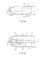
FIG. 20 is a side view schematically showing a constitution of a distal end portion of a probe and a distal end portion of a sheath according to a fourth modification of the first embodiment; -
FIG. 21 is a cross-sectional view schematically showing the constitution of the distal end portion of the probe and the distal end portion of the sheath according to the fourth modification of the first embodiment; -
FIG. 22 is a cross-sectional view taken along line 22-22 ofFIG. 20 ; -
FIG. 23 is a cross-sectional view taken along line 23-23 ofFIG. 21 ; -
FIG. 24 is a perspective view schematically showing a constitution of a distal end portion of a probe according to a second embodiment of the present invention; -
FIG. 25 is a cross-sectional view schematically showing the constitution of the distal end portion of the probe according to the second embodiment; andFIG. 26 is a schematic view showing a constitution - A first embodiment of the present invention will be described with reference to
FIG. 1 to FIG. 13 .FIG. 1 is a view showing an ultrasonic treatment device (ultrasonic surgical device) 1 of the present embodiment. It is to be noted that theultrasonic treatment device 1 of the present embodiment is an ultrasonic suction device configured to selectively shatter (disintegrate) and emulsify a living tissue by utilizing cavitation caused by ultrasonic vibration, and configured to suction the shattered and emulsified living tissue. Moreover, theultrasonic treatment device 1 has a longitudinal axis C. One of directions parallel to the longitudinal axis C is a distal direction (direction of arrow A1 inFIG. 1 ), and the other of the directions parallel to the longitudinal axis C is a proximal direction (direction of arrow A2 inFIG. 1 ). - As shown in
FIG. 1 , the ultrasonic treatment device (an ultrasonic treatment system) 1 includes an ultrasonic treatment instrument (ultrasonic treatment apparatus) including a vibrator unit (oscillator unit) 2, aprobe 3 and asheath unit 5; a power source unit 7; asuction unit 33; awater supplying unit 53; and aninput unit 9. - The
vibrator unit 2 includes a vibrator case (oscillator case) 11. One end of acable 6 is connected to a proximal end portion of thevibrator case 11. The other end of thecable 6 is connected to the power source unit 7. The power source unit 7 includes anultrasonic control section 8. The power source unit 7 is connected to theinput unit 9, for example, a foot switch. -
FIG. 2 is a view showing a constitution of thevibrator unit 2. As shown inFIG. 2 , in thevibrator case 11, an ultrasonic vibrator (ultrasonic oscillator) 12 which includes a piezoelectric element configured to convert a current into the ultrasonic vibration is provided. One end of each ofelectrical signal lines ultrasonic vibrator 12. Theelectrical signal lines cable 6, and the other ends of the electrical signal lines are connected to theultrasonic control section 8 of the power source unit 7. When the current is supplied from theultrasonic control section 8 to the ultrasonic vibrator 12 (the vibrator unit 2) through theelectrical signal lines ultrasonic vibrator 12. It is to be noted that thevibrator unit 2 and the power source unit 7 constitute an ultrasonic generation unit configured to generate the ultrasonic vibration. Ahorn 15 configured to enlarge an amplitude of the ultrasonic vibration is coupled to a distal direction side of theultrasonic vibrator 12. Thehorn 15 is attached to thevibrator case 11. Theultrasonic vibrator 12 and thehorn 15 are provided with apassage portion 19 about the longitudinal axis C. Moreover, in a distal end portion of an inner peripheral surface of thehorn 15, aninternal thread portion 16 is formed. -
FIG. 3 andFIG. 4 are views showing a constitution of theprobe 3. As shown inFIG. 3 andFIG. 4 , theprobe 3 is extended along the longitudinal axis C. Theprobe 3 includes a probedistal surface 21 and a probe outerperipheral portion 22. A distal end of the probe outerperipheral portion 22 forms an outer edge of the probedistal surface 21. A proximal end portion of the probe outerperipheral portion 22 is provided with anexternal thread portion 23 to be screwed into theinternal thread portion 16 of thehorn 15. When theexternal thread portion 23 is screwed into theinternal thread portion 16, theprobe 3 is attached to a distal direction side of thehorn 15. When theprobe 3 is attached to thehorn 15, the ultrasonic vibration generated byultrasonic vibrator 12 is transmitted to the probedistal surface 21 through thehorn 15 and theprobe 3. When the ultrasonic vibration is transmitted to the probedistal surface 21 and a liquid is supplied (forwarded) as described later, the living tissue is shattered (crushed) and emulsified with the probedistal surface 21 by utilizing a cavitation phenomenon. By the cavitation phenomenon, a tissue such as a blood vessel having a high elasticity is not shattered, and a living tissue of, for example, hepatic cells which do not have elasticity is shattered and emulsified. - It is to be noted that a length of an assembly of the
probe 3, theultrasonic vibrator 12 and thehorn 15 along the longitudinal axis C is set so that the probedistal surface 21 of theprobe 3 is an anti-node position of the ultrasonic vibration, and so that a proximal end of theultrasonic vibrator 12 becomes an anti-node position of the ultrasonic vibration. When the probedistal surface 21 becomes the anti-node position of the ultrasonic vibration, the cavitation more efficiently takes place. Moreover, the ultrasonic vibration is longitudinal vibration in which a vibration transmitting direction is in parallel with a vibrating direction, and the vibration transmitting direction and the vibrating direction are parallel to the longitudinal axis C. - As shown in
FIG. 4 , in theprobe 3, asuction passage 25 is defined by a suctionpassage defining portion 26. Thesuction passage 25 is extended along the longitudinal axis C from the distal end portion of theprobe 3. A distal end of thesuction passage 25 is positioned to a proximal direction side of the probedistal surface 21. -
FIG. 5 is a cross-sectional view taken along line V-V ofFIG. 4 . As shown inFIG. 3 andFIG. 5 , in the probe outerperipheral portion 22 of theprobe 3, two suction openings (suction ports) 28A and 28B which communicate with thesuction passage 25 are defined by a suction opening defining portion (a suction port defining portion) 29.Suction ports suction port 28A in directions parallel to the longitudinal axis C substantially coincides with (matches) a position ofsuction port 28B in the directions parallel to the longitudinal axis C. Furthermore,suction ports distal surface 21. - When the
probe 3 is attached to thehorn 15, a proximal end of thesuction passage 25 communicates with thepassage portion 19 inside theultrasonic vibrator 12 and thehorn 15. As shown inFIG. 2 , one end of asuction tube 31 is connected to thepassage portion 19. As shown inFIG. 1 , thesuction tube 31 is extended to an outside from thevibrator case 11, and has the other end connected to thesuction unit 33. Thesuction unit 33 is connected to theinput unit 9. When the living tissue resected by the cavitation is suctioned, thesuction unit 33 is driven by input in theinput unit 9, or the like. When thesuction unit 33 is driven, the resected living tissue is suctioned into thesuction passage 25 throughsuction port 28A orsuction port 28B. Then, the living tissue passes through thesuction passage 25, thepassage portion 19 and an inside of thesuction tube 31 in this order, whereby the suction of the living tissue is accomplished by thesuction unit 33. - As shown in
FIG. 3 andFIG. 5 , the probedistal surface 21 of theprobe 3 is provided continuously from the longitudinal axis C to the outer edge thereof. That is, the probedistal surface 21 is not provided with any suction ports (distal suction ports) that communicate with thesuction passage 25. Consequently, a surface area of the probedistal surface 21 increases. In this ultrasonic suction, the probedistal surface 21 is an action surface configured to shatter the living tissue by utilizing the cavitation phenomenon. Consequently, when the surface area of the probedistal surface 21 increases, an effective area where the cavitation phenomenon can be utilized increases. Therefore, the living tissue is efficiently shattered and emulsified. - As shown in
FIG. 1 , thesheath unit 5 includes asheath 41, and a holdingcase 42 configured to be held (grasped) by an operator. Thesheath 41 is extended along the longitudinal axis C, and includes a sheath outerperipheral portion 43 and a sheath innerperipheral portion 45 as shown inFIG. 6 . Moreover, theprobe 3 is inserted through thesheath 41. Theprobe 3 is inserted through thesheath 41 so that the probedistal surface 21 is positioned to the distal direction side of a distal end of thesheath 41. In other words, the probe distal surface 21 (the distal end portion) of theprobe 3 which is inserted through thesheath 41 is not covered with thesheath 41, but is exposed to the outside. Thesheath 41 is inserted into the holdingcase 42 from the distal direction side, and thevibrator unit 2 is inserted into the holding case from the proximal direction side. In the holdingcase 42, thesheath 41 is connected to thevibrator case 11. -
FIG. 6 is a view showing an inner constitution of thesheath 41 and a coupling constitution of thesheath 41 to thevibrator case 11. As shown inFIG. 6 , between the sheath innerperipheral portion 45 of thesheath 41 and the probe outerperipheral portion 22 of theprobe 3, aclearance 47 is defined by aclearance defining portion 48. Between the sheath innerperipheral portion 45 and the probe outerperipheral portion 22, theclearance 47 is extended along the longitudinal axis C from the distal end of thesheath 41. A distal end portion of a cylindricalintermediate member 49 is attached to a proximal end portion of thesheath 41. A distal end portion of thevibrator case 11 is attached to a proximal end portion of theintermediate member 49. It is to be noted that thesheath 41 may detachably be attached to theintermediate member 49 by, for example, screw fastening. - The
clearance 47 between the sheath innerperipheral portion 45 and the probe outerperipheral portion 22 is extended up to the distal surface of thevibrator case 11. One end of a liquid supplying tube (liquid forwarding tube) 51 is connected to theintermediate member 49. An inside of theliquid supplying tube 51 communicates with theclearance 47. As shown inFIG. 1 , theliquid supplying tube 51 is extended to the outside from the holdingcase 42, and is connected to the liquid supplying unit (liquid forwarding unit) 53. Theliquid supplying unit 53 is connected to theinput unit 9. When theliquid supplying unit 53 is driven by the input through theinput unit 9 or the like, a liquid such as physiological saline passes through the inside of theliquid supplying tube 51 and theclearance 47 in this order. Then, the liquid is supplied (forwarded) to the living tissue or the like through a distal end of the clearance 47 (between the distal end of the sheath innerperipheral portion 45 and the probe outer peripheral portion 22). - As described above, in the ultrasonic suction, the ultrasonic vibration is transmitted to the probe
distal surface 21 which is an anti-node position of the ultrasonic vibration. In this case, the liquid is supplied through theclearance 47, thereby causing the cavitation phenomenon. It is to be noted that the liquid may be supplied in a treatment other than the ultrasonic suction. For example, by supplying the liquid, confirmation of a bleeding spot, washing of a body cavity or the like may be performed. -
FIG. 7 andFIG. 8 show a constitution of the distal end portion of theprobe 3 and the distal end portion of thesheath 41.FIG. 9 is a cross-sectional view taken along line IX-IX ofFIG. 8 . As shown inFIG. 7 andFIG. 8 ,suction port 28A of theprobe 3 is provided at a position to face the distal end of thesheath 41. Moreover,suction port 28A of theprobe 3 has an exposedportion 55 exposed to the outside, and anon-exposed portion 56 whose outer peripheral direction side is covered with thesheath 41. That is, the exposedportion 55 does not face the sheath innerperipheral portion 45 of thesheath 41, and thenon-exposed portion 56 faces the sheath innerperipheral portion 45 of thesheath 41. In this way, a part ofsuction port 28A is thenon-exposed portion 56 whose outer peripheral direction side is covered with thesheath 41. Similarly, a part ofsuction port 28B is thenon-exposed portion 56 whose outer peripheral direction side is covered with thesheath 41. - As shown in
FIG. 7 to FIG. 9 , in the sheath outerperipheral portion 43 of thesheath 41, twoopenings clearance 47 are defined by anopening defining portion 59.Openings - Each of dimensions L1 and L2 along the longitudinal axis C between each of
openings probe tip surface 21 is 2 cm or more and 10 cm or less. Moreover, a sum of areas ofrespective openings non-exposed portions 56 ofrespective suction ports suction ports openings -
FIG. 10 and FIG. 11 are views showing a constitution of the sheath innerperipheral portion 45 in a vicinity of the oneorifice 58A. As shown inFIG. 10 and FIG. 11 , the sheath innerperipheral portion 45 includes asurface portion 61, and aconvex portion 62 projecting toward (in) an inner peripheral direction from thesurface portion 61. Thesurface portion 61 is a part of the sheath innerperipheral portion 45, and is formed into a curved or flat surface shape. Theconvex portion 62 is provided to surround a whole circumference ofopening 58A, and an outer edge ofopening 58A is formed by theconvex portion 62. - As described above, in the case of the ultrasonic suction, the liquid (the physiological saline) from the
liquid supplying unit 53 is supplied from the proximal direction to the distal direction through theclearance 47. In this case, the liquid collides with theconvex portion 62 at a position to the proximal direction side of theopening 58A. Consequently, the liquid is guided so that the liquid passes a position away from theopening 58A (arrow B1 inFIG. 11 ). Therefore, inflow of liquid to theopening 58A is prevented. That is, aninflow prevention portion 60 configured to prevent inflow of liquid to theopening 58A is formed by thesurface portion 61 and theconvex portion 62. Similarly, also for theopening 58B, theinflow prevention portion 60 configured to prevent inflow of liquid to theopening 58B is provided. - Next, an action (function) of the
ultrasonic treatment device 1 of the present embodiment will be described. When the ultrasonic suction of the living tissue is performed by using theultrasonic treatment device 1, the current is supplied from theultrasonic control section 8 to theultrasonic vibrator 12 through theelectrical signal lines input unit 9, or the like. Consequently, the ultrasonic vibration takes place in theultrasonic vibrator 12. Then, the ultrasonic vibration is transmitted to the probedistal surface 21 of theprobe 3. Moreover, a liquid such as the physiological saline is supplied to the living tissue through theclearance 47 between the probe outerperipheral portion 22 and the sheath innerperipheral portion 45 by theliquid supplying unit 53. When the ultrasonic vibration is transmitted to the probedistal surface 21 and the liquid is supplied, the cavitation takes place. By the cavitation, the living tissue of, for example, the hepatic cells having low elasticity is selectively shattered (disintegrated) and resected. - Here, the probe
distal surface 21 of theprobe 3 is provided continuously from the longitudinal axis C to the outer edge thereof. Consequently, the surface area of the probedistal surface 21 increases. In the ultrasonic suction, the probedistal surface 21 is the action surface configured to shatter the living tissue by utilizing the cavitation phenomenon. Consequently, when the surface area of the probedistal surface 21 increases, the effective area where the cavitation phenomenon can be utilized increases. Therefore, the living tissue is efficiently shattered and emulsified. - Moreover, the liquid passing through the
clearance 47 collides with theconvex portion 62 at the position to the proximal direction side of theopening 58A. Consequently, the liquid is guided to pass the position away from theopening 58A (arrow B1 inFIG. 11 ). Therefore, inflow of liquid to theopening 58A is prevented. Similarly, also for theopening 58B, inflow of liquid to theopening 58B is prevented. As described above, outflow of the liquid to the outside of thesheath 41 through theopenings - Furthermore, the living tissue resected by the cavitation is suctioned. When the
suction unit 33 is driven, the resected living tissue is suctioned into thesuction passage 25 throughsuction port 28A orsuction port 28B. Then, the living tissue passes through thesuction passage 25, thepassage portion 19 and the inside of thesuction tube 31 in this order, whereby the suction of the living tissue is accomplished by thesuction unit 33. - Here, as a first comparative example, a
probe 3a and asheath 41a shown inFIG. 12 are considered. In the first comparative example, respective suction ports 28Aa and 28Ba provided in theprobe 3a are entirely exposed to the outside. That is, differently fromsuction ports sheath 41a. Moreover, differently from the first embodiment, thesheath 41a is not provided with any openings (58A, 58B). - In the first comparative example, since respective whole suction ports 28Aa and 28Ba are exposed to the outside, the whole suction ports 28Aa and 28Ba are easily closed with a living tissue such as especially a membranous tissue in ultrasonic suction. Respective whole suction ports 28Aa and 28Ba are closed, whereby a
suction passage 25a has a negative pressure lower than an external pressure. When thesuction passage 25a is in the negative pressure state, the living tissue (the membranous tissue) firmly adheres to theprobe 3a in the vicinities of a probedistal surface 21 and suction ports 28Aa and 28Ba of a probe outerperipheral portion 22a. As a result of the living tissue adhering to theprobe 3a, treatment performance in terms of ultrasonic suction deteriorates. - Moreover, as a second comparative example, a
probe 3b and asheath 41b shown inFIG. 13 are considered. In the second comparative example, theprobe 3b is provided with four suction ports 28Ab to 28Db. Respective whole suction ports 28Ab and 28Bb are exposed to the outside. The suction ports 28Cb and 28Db are positioned to a proximal direction side of the suction ports 28Ab and 28Bb. Outer peripheral direction sides of respective whole suction ports 28Cb and 28Db are covered with thesheath 41b. That is, respective whole suction ports 28Cb and 28Db are non-exposed portions (56). Moreover, differently from the first embodiment, thesheath 41b is not provided with any openings (58A, 58B). - In the second comparative example, respective whole suction ports 28Ab and 28Bb are exposed to the outside, and hence in the ultrasonic suction, respective whole suction ports 28Ab and 28Bb are easily closed with a living tissue such as a membranous tissue. However, the outer peripheral direction sides of respective whole suction ports 28Cb and 28Db are covered with the
sheath 41b. Consequently, in the ultrasonic suction, suction ports 28Cb and 28Db are not closed with the living tissue. Therefore, a gas flows into asuction passage 25b from aclearance 47b between theprobe 3b and thesheath 41b through suction port 28Cb or suction port 28Db. - However, in the second comparative example, the
sheath 41b is not provided with the openings (58A, 58B). Therefore, when the gas flows into thesuction passage 25b through theclearance 47b, theclearance 47b has a negative pressure lower than an external pressure. When theclearance 47b is in the negative pressure state, the living tissue (the membranous tissue) firmly adheres to theprobe 3b and thesheath 41b in a vicinity of a distal end of theclearance 47b. As a result of the living tissue adhering to theprobe 3b and thesheath 41b, treatment performance in terms of ultrasonic suction deteriorates. - To solve the problem, in the present embodiment, each of the
suction ports portion 55 which is not covered with thesheath 41, and thenon-exposed portion 56 which is covered with thesheath 41. In other words, thesheath 41 is set to such a length (dimension) that the distal end portion (the probe distal surface 21) of theprobe 3 is exposed and that a part of each ofsuction ports probe 3 is inserted through the sheath. Therefore, in the ultrasonic suction, thenon-exposed portions 56 ofsuction ports sheath 41 is provided with theopenings clearance 47. Consequently, in the ultrasonic suction, the gas flows into theclearance 47 between the probe outerperipheral portion 22 and the sheath innerperipheral portion 45 from the outside of thesheath 41 throughopening 58A oropening 58B. Then, the gas flows into thesuction passage 25 of theprobe 3 from theclearance 47 through thenon-exposed portion 56 ofsuction port 28A or thenon-exposed portion 56 ofsuction port 28B. Therefore, in the ultrasonic suction, the pressure of theclearance 47 and thesuction passage 25 is about the same as the external pressure, and theclearance 47 and thesuction passage 25 are not in the negative pressure state. Consequently, the adhesion of the living tissue to theprobe 3 and thesheath 41 is effectively prevented, and the ultrasonic suction is efficiently performed. - Furthermore, the sum of the areas of
respective openings non-exposed portions 56 ofrespective suction ports clearance 47 from the outside of thesheath 41 through theopening 58A or theopening 58B becomes greater than the amount of gas flowing into thesuction passage 25 from theclearance 47 through thenon-exposed portion 56 ofsuction port 28A or thenon-exposed portion 56 ofsuction port 28B. Therefore, change of theclearance 47 to the negative pressure state is further effectively prevented, and the adhesion of the living tissue to theprobe 3 and thesheath 41 is further effectively prevented. - Moreover,
suction ports orifices suction ports distal surface 21 of theprobe 3. Consequently, the living tissue shattered and emulsified with the probedistal surface 21 by utilizing the cavitation is easily suctioned throughsuction port 28A orsuction port 28B. Therefore, in the ultrasonic suction, the living tissue is efficiently suctioned. - Additionally, each of dimensions L1 and L2 along the longitudinal axis C between each of
openings distal surface 21 is 2 cm or more and 10 cm or less. When each of dimensions L1 and L2 is smaller than 2 cm, the positions of the openings (58A, 58B) come close to the living tissue to be treated by the ultrasonic suction. Consequently, the openings (58A, 58B) are easily closed with the living tissue (membranous tissue). When the openings (58A, 58B) are closed, the gas does not easily flow into theclearance 47 through the opening (58A or 58B), and theclearance 47 easily becomes the negative pressure state. Therefore, when each of dimensions L1 and L2 is 2 cm or more, the closing ofopenings clearance 47 to the negative pressure state is further effectively prevented. - On the other hand, when each of dimensions L1 and L2 is greater than 10 cm, the openings (58A, 58B) are positioned on an outside of a body in a treatment such as the ultrasonic suction. Consequently, at the treatment, the gas might flow into a body cavity from the outside of the body through the opening (58A or 58B). As a result of the gas flowing into the body cavity from outside the body, treatment performance may deteriorate. Therefore, each of dimensions L1 and L2 is set to 10 cm or less, whereby at the treatment,
openings - Accordingly, the
ultrasonic treatment device 1 of the above constitution produces the following effects. That is, in theultrasonic treatment device 1 of the present embodiment, a part of each of thesuction ports non-exposed portion 56 whose outer peripheral direction side is covered with thesheath 41. Consequently, in the ultrasonic suction, thenon-exposed portions 56 ofrespective suction ports sheath 41 is provided withopenings clearance 47. Consequently, in the ultrasonic suction, the gas flows into theclearance 47 between the probe outerperipheral portion 22 and the sheath innerperipheral portion 45 from the outside of thesheath 41 throughopening 58A oropening 58B. Then, the gas flows into thesuction passage 25 of theprobe 3 from theclearance 47 through thenon-exposed portion 56 ofsuction port 28A or thenon-exposed portion 56 ofsuction port 28B. Therefore, in the ultrasonic suction, the pressure of theclearance 47 and thesuction passage 25 is about the same as the external pressure, and theclearance 47 and thesuction passage 25 do not become the negative pressure state. Therefore, the adhesion of the living tissue to theprobe 3 and thesheath 41 can be effectively prevented, and the ultrasonic suction can be efficiently performed. - Moreover, in the
ultrasonic treatment device 1, the sum of the areas ofrespective openings non-exposed portions 56 ofrespective suction ports clearance 47 from the outside of thesheath 41 throughopening 58A oropening 58B is greater than the amount of gas flowing into thesuction passage 25 from theclearance 47 through thenon-exposed portion 56 ofsuction port 28A or thenon-exposed portion 56 ofsuction port 28B. Therefore, the change of theclearance 47 to the negative pressure state can be further effectively prevented, and the adhesion of the living tissue to theprobe 3 and thesheath 41 can be further effectively prevented. - Furthermore, in the
ultrasonic treatment device 1,suction ports openings suction ports distal surface 21 of theprobe 3. Consequently, the living tissue shattered and emulsified with the probedistal surface 21 by utilizing the cavitation is easily suctioned throughsuction port 28A orsuction port 28B. Therefore, in the ultrasonic suction, the living tissue can be efficiently suctioned. - Additionally, in the
ultrasonic treatment device 1, each of dimensions L1 and L2 along the longitudinal axis C between each ofopenings distal surface 21 is 2 cm or more and 10 cm or less. When each of dimensions L1 and L2 is 2 cm or more, the closing ofopenings clearance 47 to the negative pressure state can be further effectively prevented. Moreover, when each of dimensions L1 and L2 is 10 cm or less,openings - Moreover, in the
ultrasonic treatment device 1, the probedistal surface 21 of theprobe 3 is provided continuously from the longitudinal axis C to the outer edge thereof. Consequently, the surface area of the probedistal surface 21 increases. In the ultrasonic suction, the probedistal surface 21 is the action surface configured to shatter the living tissue by utilizing the cavitation phenomenon. Consequently, when the surface area of the probedistal surface 21 increases, the effective area where the cavitation phenomenon can be utilized increases. Therefore, the living tissue can be efficiently shattered and emulsified. - Furthermore, in the
ultrasonic treatment device 1, the liquid passing through theclearance 47 between the probe outerperipheral portion 22 and the sheath innerperipheral portion 45 collides with theconvex portion 62 at the position to the proximal direction side ofopening 58A. Consequently, the liquid is guided to pass the position away from theopening 58A (arrow B1 inFIG. 11 ). Therefore, inflow of liquid to opening 58A is prevented. Similarly, also for theopening 58B, inflow of liquid toopening 58B is prevented. As described above, the outflow of the liquid through theopenings sheath 41 can be effectively prevented. Therefore, the supplying of the liquid to the living tissue to be ultrasonically suctioned can be efficiently performed. - It is to be noted that in the first embodiment, the
convex portion 62 is provided to surround the whole periphery of theopening 58A, and the outer edge of theopening 58A is formed by theconvex portion 62, but the present invention is not limited to this embodiment. For example, as a first modification shown inFIG. 14 and FIG. 15 , aconvex portion 62 may be provided away from anopening 58A toward a proximal directione side. In the present modification, the whole periphery of theopening 58A is not surrounded by theconvex portion 62. Moreover, the outer edge of opening 58A is not formed by theconvex portion 62, and asurface portion 61 is provided (interposed) continuously between theopening 58A and theconvex portion 62. - However, also in the present modification, similarly to the first embodiment, a liquid collides with the
convex portion 62 at a position to the proximal direction side ofopening 58A. Consequently, the liquid is guided to pass a position away from opening 58A (arrow B2 inFIG. 15 ). Therefore, inflow of liquid to theopening 58A is prevented. That is, aninflow prevention portion 60 configured to prevent inflow of liquid to theopening 58A is formed by thesurface portion 61 and theconvex portion 62. It is to be noted that also for anopening 58B, inflow of liquid toopening 58B may be prevented by using theinflow prevention portion 60 of the present modification. - Moreover, in the first embodiment and the first modification, the
inflow prevention portion 60 has the constitution including thesurface portion 61 and theconvex portion 62, but the present invention is not limited to these embodiments. For example, as a second modification shown inFIG. 16 and 17 , inflow of liquid to anopening 58A may be prevented by aninflow prevention portion 65 having a constitution different from that of theinflow prevention portion 60. Theinflow prevention portion 65 of the present modification includes a raised portion 66 which is provided in a sheath innerperipheral portion 45 with surrounding theopening 58A. The raised portion 66 is provided over a predetermined region around (about)opening 58A. In the raised portion, as it goes toward theopening 58A, the sheath innerperipheral portion 45 is positioned toward an inner peripheral direction side. When the raised portion 66 is provided, a liquid to be supplied through aclearance 47 is guided so that the liquid does not pass the raised portion 66 (arrow B3 inFIG. 17 ). That is, the liquid is guided to pass a position away from theopening 58A. Consequently, inflow of liquid to opening 58A is prevented. It is to be noted that also for anopening 58B, inflow of liquid to theopening 58B may be prevented by using theinflow prevention portion 65 of the present modification. - Furthermore, for example, as a third modification shown in
FIG. 18 and FIG. 19 , inflow of liquid to anopening 58A may be prevented by aninflow prevention portion 70 having a constitution different from those of theinflow prevention portions inflow prevention portion 70 of the present modification includes asurface portion 71, and aconcave portion 72 in a dented state toward an outer peripheral direction side from thesurface portion 71. Thesurface portion 71 becomes a part of a sheath innerperipheral portion 45, and is formed into a curved or flat surface shape. Theconcave portion 72 is provided at a position away from opening 58A. Theconcave portion 72 is extended from a position to a proximal direction side of theopening 58A up to a position to a distal direction side of theopening 58A. That is, a proximal end of theconcave portion 72 is positioned to the proximal direction side of theopening 58A, and the distal end of theconcave portion 72 is positioned to the distal direction side of theopening 58A. - A liquid to be supplied through a
clearance 47 flows into theconcave portion 72 at the position to the proximal direction side of theopening 58A. Then, the liquid flows along theconcave portion 72, and is guided to the distal direction side of theopening 58A (arrow B4 inFIG. 19 ). Here, theconcave portion 72 is provided at the position away from opening 58A. Consequently, the liquid which has flowed into theconcave portion 72 is guided to pass the position away from opening 58A, by theconcave portion 72. Consequently, inflow of liquid to theopening 58A is prevented. It is to be noted that also for anopening 58B, inflow of liquid to theopening 58B may be prevented by using theinflow prevention portion 70 of the present modification. - As understood from the above first to third modifications, the sheath inner
peripheral portion 45 may be provided with the inflow prevention portion (60, 65, 70) configured to prevent inflow, to the opening (58A, 58B), of the liquid to be supplied from the proximal direction to the distal direction through theclearance 47. - Moreover, in the first embodiment, the two
suction ports respective suction ports portion 55 and thenon-exposed portion 56, but the present invention is not limited to this embodiment. Furthermore, in the first embodiment, the twoopenings - For example, as a fourth modification shown in
FIG. 20 to FIG. 23 , twosuction ports suction ports peripheral portion 22.Suction ports suction port 28C in directions parallel to the longitudinal axis C substantially coincides with a position ofsuction port 28D in the directions parallel to the longitudinal axis C. Each ofrespective suction ports portion 55 and anon-exposed portion 56 similarly to the first embodiment. Furthermore, each ofrespective suction ports non-exposed portion 56 whose outer peripheral direction side is covered with asheath 41. That is, respectivewhole suction ports non-exposed portions 56. - In a sheath outer
peripheral portion 43, only oneopening 58A having a substantially quadrangular shape is provided. Also in the present modification, the dimension along the longitudinal axis C between theopening 58A and a probedistal surface 21 is 2 cm or more and 10 cm or less. Moreover, also in the present modification, the area of theopening 58A is greater than the total area of thenon-exposed portions 56 ofrespective suction port 28A to 28D. Furthermore, thesuction ports opening 58A. - As understood from the above fourth modification, at least one suction port (28A-28D) may be provided to a probe outer
peripheral portion 22. Moreover, at least a part (portion) of each of the suction port (28A-28D) may be thenon-exposed portion 56 whose outer peripheral direction side is covered with thesheath 41. Furthermore, the sheath outer peripheral portion may be provided with at least one opening (58A, 58B). According to such a constitution, in ultrasonic suction, the pressure of aclearance 47 and asuction passage 25 is about the same as an external pressure, and theclearance 47 and thesuction passage 25 do not attain a negative pressure state. - Moreover, the sum of the areas of the respective openings (58A, 58B) may be not less than the sum of the areas of the
non-exposed portions 56 of the respective suction ports (28A-28D). Consequently, change of theclearance 47 to the negative pressure state is further effectively prevented. Furthermore, the suction ports (28A, 28B) positioned on the most distal direction side may be positioned to the distal direction side of the openings (58A, 58B) positioned on the most distal direction side. Consequently, a living tissue shattered and emulsified with the probedistal surface 21 by utilizing cavitation is easily suctioned throughsuction port 28A orsuction port 28B. Furthermore, the dimension along the longitudinal axis C between each opening (58A, 58B) and the probedistal surface 21 may be 2 cm or more and 10 cm or less. Consequently, closing ofopenings - Next, a second embodiment of the present invention will be described with reference to
FIG. 24 to FIG. 26 . In the second embodiment, the constitution of the first embodiment is modified as follows. It is to be noted that a constitution common to the first embodiment is denoted with the same reference marks, and description of the constitution is omitted. - As shown in
FIG. 24 and FIG. 25 , according to anultrasonic treatment device 1 of the present embodiment, in a probedistal surface 21, adistal suction port 75 which communicates with asuction passage 25 is defined by a distal suctionport defining portion 76. That is, the probedistal surface 21 is provided discontinuously from a longitudinal axis C to an outer edge thereof. - As shown in
FIG. 26 , in the present embodiment,suction ports openings respective suction ports non-exposed portion 56 whose outer peripheral direction side is covered. That is, respectivewhole suction ports non-exposed portions 56. - It is to be noted that also in the present embodiment, similarly to the first embodiment, a sum of areas of
respective openings non-exposed portions 56 ofrespective suction ports respective openings distal surface 21 is 2 cm or more and 10 cm or less. - In the present embodiment, the probe
distal surface 21 is provided with thedistal suction port 75. Consequently, it is not necessary to suction, throughsuction port 28A orsuction port 28B, a living tissue shattered and emulsified with the probedistal surface 21 by utilizing cavitation, and the living tissue is easily suctioned through thedistal suction port 75. Therefore, in ultrasonic suction, the living tissue can be efficiently suctioned through thedistal suction port 75 irrespective of the positions ofsuction ports - Incidentally, the present invention is not limited to the above embodiments and various modifications can naturally be made without deviating from the spirit and scope of the present invention.
Claims (9)
- An ultrasonic treatment device comprising:a sheath which includes a sheath outer peripheral portion and a sheath inner peripheral portion, and which is extended along a longitudinal axis;a probe which includes a probe distal surface and a probe outer peripheral portion, and which is inserted through the sheath in a state that the probe distal surface is positioned to a distal direction side of a distal end of the sheath;a suction passage defining portion which defines a suction passage along the longitudinal axis inside the probe;a clearance defining portion which defines a clearance between the sheath inner peripheral portion and the probe outer peripheral portion;a suction port defining portion which defines a suction port, the suction port communicating with the suction passage, in the probe outer peripheral portion in a state that a part of the suction port becomes a non-exposed portion whose outer peripheral direction side is covered with the sheath; andan opening defining portion which defines an opening in the sheath outer peripheral portion, the opening communicating with the clearance.
- The ultrasonic treatment device according to claim 1,
wherein the suction port defining portion defines the at least one suction port, and
the opening defining portion defines the at least one opening so that a sum of area of the respective opening is not less than a sum of area of the non-exposed portion of the respective suction port. - The ultrasonic treatment device according to claim 1,
wherein the sheath inner peripheral portion includes an inflow prevention portion configured to prevent inflow, to the opening, of a liquid to be supplied from a proximal direction to the distal direction through the clearance. - The ultrasonic treatment device according to claim 3,
wherein the inflow prevention portion includes:a surface portion which becomes a part of the sheath inner peripheral portion; anda convex portion which projects toward an inner peripheral direction from the surface portion, and with which the liquid is configured to collide at a position to the proximal direction side of the opening, the convex portion being configured to guide the collided liquid so that the liquid passes a position away from the opening. - The ultrasonic treatment device according to claim 3,
wherein the inflow prevention portion includes a raised portion which is provided in the sheath inner peripheral portion with surrounding the opening, the sheath inner peripheral portion being positioned toward an inner peripheral side in the raised portion as it goes toward the opening, and the raised portion being configured to guide the liquid so that the liquid passes a position away from the opening. - The ultrasonic treatment device according to claim 3,
wherein the inflow prevention portion includes:a surface portion which becomes a part of the sheath inner peripheral portion; anda concave portion which is provided at a position away from the opening with denting toward the outer peripheral direction side from the surface portion, and into which the liquid is configured to inflow at a position to the proximal direction side of the opening, the concave portion being configured to flow the inflowed liquid along the concave portion and thereby configured to guide the inflowed liquid so that the liquid passes the position away from the opening. - The ultrasonic treatment device according to claim 1,
wherein the probe distal surface is provided continuously from the longitudinal axis to an outer edge thereof,
the opening defining portion defines the at least one opening, and
the suction port defining portion defines the at least one suction port so that the suction port positioned on the most distal direction side is positioned to the distal direction side of the opening positioned on the most distal direction side. - The ultrasonic treatment, device according to claim 1, further comprising:a distal suction port defining portion which defines a distal suction port in the probe distal surface, the distal suction port communicating with the suction passage.
- The ultrasonic treatment device according to claim 1,
wherein the opening defining portion defines the at least one opening so that a dimension along the longitudinal axis between the opening and the probe distal surface is 2 cm or more and 10 cm or less.
Applications Claiming Priority (2)
| Application Number | Priority Date | Filing Date | Title |
|---|---|---|---|
| US201161528448P | 2011-08-29 | 2011-08-29 | |
| PCT/JP2012/070041 WO2013031490A1 (en) | 2011-08-29 | 2012-08-07 | Ultrasonic wave processing device |
Publications (3)
| Publication Number | Publication Date |
|---|---|
| EP2649954A1 true EP2649954A1 (en) | 2013-10-16 |
| EP2649954A4 EP2649954A4 (en) | 2014-03-26 |
| EP2649954B1 EP2649954B1 (en) | 2015-09-30 |
Family
ID=47755992
Family Applications (1)
| Application Number | Title | Priority Date | Filing Date |
|---|---|---|---|
| EP12828468.4A Active EP2649954B1 (en) | 2011-08-29 | 2012-08-07 | Ultrasonic wave processing device |
Country Status (5)
| Country | Link |
|---|---|
| US (1) | US20130274636A1 (en) |
| EP (1) | EP2649954B1 (en) |
| JP (1) | JP5296944B1 (en) |
| CN (1) | CN103370022B (en) |
| WO (1) | WO2013031490A1 (en) |
Families Citing this family (1)
| Publication number | Priority date | Publication date | Assignee | Title |
|---|---|---|---|---|
| WO2014100606A1 (en) * | 2012-12-21 | 2014-06-26 | Meyer, Douglas | Rotational ultrasound imaging catheter with extended catheter body telescope |
Citations (5)
| Publication number | Priority date | Publication date | Assignee | Title |
|---|---|---|---|---|
| US5163433A (en) * | 1989-11-01 | 1992-11-17 | Olympus Optical Co., Ltd. | Ultrasound type treatment apparatus |
| US6050971A (en) * | 1998-01-21 | 2000-04-18 | Garnier; Bernard | Suction control device for an apparatus used in microsurgery in particular in ophthalmic surgery |
| US6159175A (en) * | 1995-06-02 | 2000-12-12 | Surgical Design Corporation | Phacoemulsification handpiece, sleeve, and tip |
| US20060100653A1 (en) * | 2004-07-20 | 2006-05-11 | Takayuki Akahoshi | Infusion sleeve |
| JP2006144364A (en) * | 2004-11-18 | 2006-06-08 | Kyushu Electric Power Co Inc | Refuse inflow preventing tool |
Family Cites Families (10)
| Publication number | Priority date | Publication date | Assignee | Title |
|---|---|---|---|---|
| US4493694A (en) * | 1980-10-17 | 1985-01-15 | Cooper Lasersonics, Inc. | Surgical pre-aspirator |
| JP2660069B2 (en) * | 1989-11-07 | 1997-10-08 | オリンパス光学工業株式会社 | Ultrasound therapy equipment |
| US5397293A (en) * | 1992-11-25 | 1995-03-14 | Misonix, Inc. | Ultrasonic device with sheath and transverse motion damping |
| JP4216960B2 (en) | 1999-07-19 | 2009-01-28 | オリンパス株式会社 | Ultrasonic suction device |
| US20020077550A1 (en) * | 1999-10-05 | 2002-06-20 | Rabiner Robert A. | Apparatus and method for treating gynecological diseases using an ultrasonic medical device operating in a transverse mode |
| AU2003209629A1 (en) * | 2002-08-05 | 2004-02-23 | Gil Ofir | Embolism filter with self-deployable guidewire stop |
| US7276060B2 (en) * | 2004-02-26 | 2007-10-02 | Alcon, Inc. | Surgical handpiece tip |
| US7682378B2 (en) * | 2004-11-10 | 2010-03-23 | Dfine, Inc. | Bone treatment systems and methods for introducing an abrading structure to abrade bone |
| WO2010022103A1 (en) * | 2008-08-18 | 2010-02-25 | Cianna Medical, Inc. | Brachytherapy apparatus, systems, and methods for using them |
| US9351871B2 (en) * | 2008-11-12 | 2016-05-31 | Alcon Research, Ltd. | Distal plastic end infusion/aspiration tip |
-
2012
- 2012-08-07 EP EP12828468.4A patent/EP2649954B1/en active Active
- 2012-08-07 CN CN201280008361.XA patent/CN103370022B/en active Active
- 2012-08-07 WO PCT/JP2012/070041 patent/WO2013031490A1/en active Application Filing
- 2012-08-07 JP JP2013510375A patent/JP5296944B1/en not_active Expired - Fee Related
-
2013
- 2013-03-11 US US13/794,015 patent/US20130274636A1/en not_active Abandoned
Patent Citations (5)
| Publication number | Priority date | Publication date | Assignee | Title |
|---|---|---|---|---|
| US5163433A (en) * | 1989-11-01 | 1992-11-17 | Olympus Optical Co., Ltd. | Ultrasound type treatment apparatus |
| US6159175A (en) * | 1995-06-02 | 2000-12-12 | Surgical Design Corporation | Phacoemulsification handpiece, sleeve, and tip |
| US6050971A (en) * | 1998-01-21 | 2000-04-18 | Garnier; Bernard | Suction control device for an apparatus used in microsurgery in particular in ophthalmic surgery |
| US20060100653A1 (en) * | 2004-07-20 | 2006-05-11 | Takayuki Akahoshi | Infusion sleeve |
| JP2006144364A (en) * | 2004-11-18 | 2006-06-08 | Kyushu Electric Power Co Inc | Refuse inflow preventing tool |
Non-Patent Citations (1)
| Title |
|---|
| See also references of WO2013031490A1 * |
Also Published As
| Publication number | Publication date |
|---|---|
| EP2649954B1 (en) | 2015-09-30 |
| JP5296944B1 (en) | 2013-09-25 |
| CN103370022B (en) | 2015-11-25 |
| JPWO2013031490A1 (en) | 2015-03-23 |
| US20130274636A1 (en) | 2013-10-17 |
| CN103370022A (en) | 2013-10-23 |
| WO2013031490A1 (en) | 2013-03-07 |
| EP2649954A4 (en) | 2014-03-26 |
Similar Documents
| Publication | Publication Date | Title |
|---|---|---|
| EP2644144B1 (en) | Bipolar treatment device | |
| JP4266788B2 (en) | Fluid ejection device | |
| JP4778545B2 (en) | Fluid ejection device | |
| EP1927321B1 (en) | Probe for ultrasonic treatment apparatus | |
| US8574228B2 (en) | Ultrasound treatment system | |
| CN107205763B (en) | Ultrasonic treatment tool and ultrasonic treatment unit | |
| JP2004525737A (en) | Ultrasound device for ablation of tissue and sheath for use with the device | |
| EP2636382A1 (en) | Ultrasonic probe | |
| JP6022128B2 (en) | Energy treatment unit, energy treatment device and energy treatment system | |
| EP2692305B1 (en) | Ultrasound therapy device | |
| EP2649954A1 (en) | Ultrasonic wave processing device | |
| JP5478764B2 (en) | Ultrasonic probe and ultrasonic treatment apparatus | |
| JP7238119B2 (en) | Ultrasonic treatment device, ultrasonic therapy system, and endoscopic surgery system | |
| JP5663706B2 (en) | Ultrasonic probe | |
| EP3000424B1 (en) | Ultrasonic treatment device | |
| JPH03151954A (en) | Ultrasonic curing apparatus | |
| JP6033503B1 (en) | Ultrasonic treatment device and ultrasonic treatment assembly | |
| JPS61191350A (en) | Surgical operation tool | |
| JPS63309249A (en) | Ultrasonic treatment apparatus | |
| JPH0321231A (en) | Ultrasonic medical instrument |
Legal Events
| Date | Code | Title | Description |
|---|---|---|---|
| PUAI | Public reference made under article 153(3) epc to a published international application that has entered the european phase |
Free format text: ORIGINAL CODE: 0009012 |
|
| 17P | Request for examination filed |
Effective date: 20130709 |
|
| AK | Designated contracting states |
Kind code of ref document: A1 Designated state(s): AL AT BE BG CH CY CZ DE DK EE ES FI FR GB GR HR HU IE IS IT LI LT LU LV MC MK MT NL NO PL PT RO RS SE SI SK SM TR |
|
| A4 | Supplementary search report drawn up and despatched |
Effective date: 20140224 |
|
| RIC1 | Information provided on ipc code assigned before grant |
Ipc: A61B 17/32 20060101ALN20140218BHEP Ipc: A61B 18/00 20060101AFI20140218BHEP |
|
| GRAP | Despatch of communication of intention to grant a patent |
Free format text: ORIGINAL CODE: EPIDOSNIGR1 |
|
| RIC1 | Information provided on ipc code assigned before grant |
Ipc: A61B 18/00 20060101AFI20150303BHEP Ipc: A61B 17/32 20060101ALN20150303BHEP |
|
| INTG | Intention to grant announced |
Effective date: 20150327 |
|
| GRAS | Grant fee paid |
Free format text: ORIGINAL CODE: EPIDOSNIGR3 |
|
| GRAA | (expected) grant |
Free format text: ORIGINAL CODE: 0009210 |
|
| AK | Designated contracting states |
Kind code of ref document: B1 Designated state(s): AL AT BE BG CH CY CZ DE DK EE ES FI FR GB GR HR HU IE IS IT LI LT LU LV MC MK MT NL NO PL PT RO RS SE SI SK SM TR |
|
| REG | Reference to a national code |
Ref country code: CH Ref legal event code: EP Ref country code: GB Ref legal event code: FG4D |
|
| REG | Reference to a national code |
Ref country code: AT Ref legal event code: REF Ref document number: 751914 Country of ref document: AT Kind code of ref document: T Effective date: 20151015 Ref country code: CH Ref legal event code: PUE Owner name: OLYMPUS CORPORATION, JP Free format text: FORMER OWNER: OLYMPUS MEDICAL SYSTEMS CORP., JP |
|
| REG | Reference to a national code |
Ref country code: IE Ref legal event code: FG4D |
|
| RAP2 | Party data changed (patent owner data changed or rights of a patent transferred) |
Owner name: OLYMPUS CORPORATION |
|
| REG | Reference to a national code |
Ref country code: DE Ref legal event code: R096 Ref document number: 602012011239 Country of ref document: DE |
|
| PG25 | Lapsed in a contracting state [announced via postgrant information from national office to epo] |
Ref country code: LT Free format text: LAPSE BECAUSE OF FAILURE TO SUBMIT A TRANSLATION OF THE DESCRIPTION OR TO PAY THE FEE WITHIN THE PRESCRIBED TIME-LIMIT Effective date: 20150930 Ref country code: FI Free format text: LAPSE BECAUSE OF FAILURE TO SUBMIT A TRANSLATION OF THE DESCRIPTION OR TO PAY THE FEE WITHIN THE PRESCRIBED TIME-LIMIT Effective date: 20150930 Ref country code: LV Free format text: LAPSE BECAUSE OF FAILURE TO SUBMIT A TRANSLATION OF THE DESCRIPTION OR TO PAY THE FEE WITHIN THE PRESCRIBED TIME-LIMIT Effective date: 20150930 Ref country code: NO Free format text: LAPSE BECAUSE OF FAILURE TO SUBMIT A TRANSLATION OF THE DESCRIPTION OR TO PAY THE FEE WITHIN THE PRESCRIBED TIME-LIMIT Effective date: 20151230 Ref country code: GR Free format text: LAPSE BECAUSE OF FAILURE TO SUBMIT A TRANSLATION OF THE DESCRIPTION OR TO PAY THE FEE WITHIN THE PRESCRIBED TIME-LIMIT Effective date: 20151231 |
|
| REG | Reference to a national code |
Ref country code: DE Ref legal event code: R082 Ref document number: 602012011239 Country of ref document: DE Representative=s name: WUESTHOFF & WUESTHOFF, PATENTANWAELTE PARTG MB, DE Ref country code: DE Ref legal event code: R081 Ref document number: 602012011239 Country of ref document: DE Owner name: OLYMPUS CORPORATION, JP Free format text: FORMER OWNER: OLYMPUS MEDICAL SYSTEMS CORP., TOKYO, JP |
|
| REG | Reference to a national code |
Ref country code: NL Ref legal event code: MP Effective date: 20150930 |
|
| REG | Reference to a national code |
Ref country code: LT Ref legal event code: MG4D |
|
| REG | Reference to a national code |
Ref country code: AT Ref legal event code: MK05 Ref document number: 751914 Country of ref document: AT Kind code of ref document: T Effective date: 20150930 |
|
| PG25 | Lapsed in a contracting state [announced via postgrant information from national office to epo] |
Ref country code: SE Free format text: LAPSE BECAUSE OF FAILURE TO SUBMIT A TRANSLATION OF THE DESCRIPTION OR TO PAY THE FEE WITHIN THE PRESCRIBED TIME-LIMIT Effective date: 20150930 Ref country code: RS Free format text: LAPSE BECAUSE OF FAILURE TO SUBMIT A TRANSLATION OF THE DESCRIPTION OR TO PAY THE FEE WITHIN THE PRESCRIBED TIME-LIMIT Effective date: 20150930 Ref country code: HR Free format text: LAPSE BECAUSE OF FAILURE TO SUBMIT A TRANSLATION OF THE DESCRIPTION OR TO PAY THE FEE WITHIN THE PRESCRIBED TIME-LIMIT Effective date: 20150930 |
|
| PG25 | Lapsed in a contracting state [announced via postgrant information from national office to epo] |
Ref country code: CZ Free format text: LAPSE BECAUSE OF FAILURE TO SUBMIT A TRANSLATION OF THE DESCRIPTION OR TO PAY THE FEE WITHIN THE PRESCRIBED TIME-LIMIT Effective date: 20150930 Ref country code: IT Free format text: LAPSE BECAUSE OF FAILURE TO SUBMIT A TRANSLATION OF THE DESCRIPTION OR TO PAY THE FEE WITHIN THE PRESCRIBED TIME-LIMIT Effective date: 20150930 Ref country code: ES Free format text: LAPSE BECAUSE OF FAILURE TO SUBMIT A TRANSLATION OF THE DESCRIPTION OR TO PAY THE FEE WITHIN THE PRESCRIBED TIME-LIMIT Effective date: 20150930 Ref country code: IS Free format text: LAPSE BECAUSE OF FAILURE TO SUBMIT A TRANSLATION OF THE DESCRIPTION OR TO PAY THE FEE WITHIN THE PRESCRIBED TIME-LIMIT Effective date: 20160130 Ref country code: EE Free format text: LAPSE BECAUSE OF FAILURE TO SUBMIT A TRANSLATION OF THE DESCRIPTION OR TO PAY THE FEE WITHIN THE PRESCRIBED TIME-LIMIT Effective date: 20150930 Ref country code: NL Free format text: LAPSE BECAUSE OF FAILURE TO SUBMIT A TRANSLATION OF THE DESCRIPTION OR TO PAY THE FEE WITHIN THE PRESCRIBED TIME-LIMIT Effective date: 20150930 Ref country code: SK Free format text: LAPSE BECAUSE OF FAILURE TO SUBMIT A TRANSLATION OF THE DESCRIPTION OR TO PAY THE FEE WITHIN THE PRESCRIBED TIME-LIMIT Effective date: 20150930 |
|
| PG25 | Lapsed in a contracting state [announced via postgrant information from national office to epo] |
Ref country code: PL Free format text: LAPSE BECAUSE OF FAILURE TO SUBMIT A TRANSLATION OF THE DESCRIPTION OR TO PAY THE FEE WITHIN THE PRESCRIBED TIME-LIMIT Effective date: 20150930 Ref country code: AT Free format text: LAPSE BECAUSE OF FAILURE TO SUBMIT A TRANSLATION OF THE DESCRIPTION OR TO PAY THE FEE WITHIN THE PRESCRIBED TIME-LIMIT Effective date: 20150930 Ref country code: PT Free format text: LAPSE BECAUSE OF FAILURE TO SUBMIT A TRANSLATION OF THE DESCRIPTION OR TO PAY THE FEE WITHIN THE PRESCRIBED TIME-LIMIT Effective date: 20160201 Ref country code: RO Free format text: LAPSE BECAUSE OF FAILURE TO SUBMIT A TRANSLATION OF THE DESCRIPTION OR TO PAY THE FEE WITHIN THE PRESCRIBED TIME-LIMIT Effective date: 20150930 |
|
| REG | Reference to a national code |
Ref country code: DE Ref legal event code: R097 Ref document number: 602012011239 Country of ref document: DE |
|
| PLBE | No opposition filed within time limit |
Free format text: ORIGINAL CODE: 0009261 |
|
| STAA | Information on the status of an ep patent application or granted ep patent |
Free format text: STATUS: NO OPPOSITION FILED WITHIN TIME LIMIT |
|
| PG25 | Lapsed in a contracting state [announced via postgrant information from national office to epo] |
Ref country code: DK Free format text: LAPSE BECAUSE OF FAILURE TO SUBMIT A TRANSLATION OF THE DESCRIPTION OR TO PAY THE FEE WITHIN THE PRESCRIBED TIME-LIMIT Effective date: 20150930 |
|
| 26N | No opposition filed |
Effective date: 20160701 |
|
| PG25 | Lapsed in a contracting state [announced via postgrant information from national office to epo] |
Ref country code: SI Free format text: LAPSE BECAUSE OF FAILURE TO SUBMIT A TRANSLATION OF THE DESCRIPTION OR TO PAY THE FEE WITHIN THE PRESCRIBED TIME-LIMIT Effective date: 20150930 |
|
| PG25 | Lapsed in a contracting state [announced via postgrant information from national office to epo] |
Ref country code: BE Free format text: LAPSE BECAUSE OF FAILURE TO SUBMIT A TRANSLATION OF THE DESCRIPTION OR TO PAY THE FEE WITHIN THE PRESCRIBED TIME-LIMIT Effective date: 20150930 |
|
| PG25 | Lapsed in a contracting state [announced via postgrant information from national office to epo] |
Ref country code: MC Free format text: LAPSE BECAUSE OF FAILURE TO SUBMIT A TRANSLATION OF THE DESCRIPTION OR TO PAY THE FEE WITHIN THE PRESCRIBED TIME-LIMIT Effective date: 20150930 |
|
| REG | Reference to a national code |
Ref country code: CH Ref legal event code: PL |
|
| GBPC | Gb: european patent ceased through non-payment of renewal fee |
Effective date: 20160807 |
|
| PG25 | Lapsed in a contracting state [announced via postgrant information from national office to epo] |
Ref country code: LI Free format text: LAPSE BECAUSE OF NON-PAYMENT OF DUE FEES Effective date: 20160831 Ref country code: CH Free format text: LAPSE BECAUSE OF NON-PAYMENT OF DUE FEES Effective date: 20160831 |
|
| REG | Reference to a national code |
Ref country code: FR Ref legal event code: ST Effective date: 20170428 |
|
| REG | Reference to a national code |
Ref country code: IE Ref legal event code: MM4A |
|
| PG25 | Lapsed in a contracting state [announced via postgrant information from national office to epo] |
Ref country code: GB Free format text: LAPSE BECAUSE OF NON-PAYMENT OF DUE FEES Effective date: 20160807 Ref country code: FR Free format text: LAPSE BECAUSE OF NON-PAYMENT OF DUE FEES Effective date: 20160831 Ref country code: IE Free format text: LAPSE BECAUSE OF NON-PAYMENT OF DUE FEES Effective date: 20160807 |
|
| PG25 | Lapsed in a contracting state [announced via postgrant information from national office to epo] |
Ref country code: LU Free format text: LAPSE BECAUSE OF NON-PAYMENT OF DUE FEES Effective date: 20160807 |
|
| PG25 | Lapsed in a contracting state [announced via postgrant information from national office to epo] |
Ref country code: CY Free format text: LAPSE BECAUSE OF FAILURE TO SUBMIT A TRANSLATION OF THE DESCRIPTION OR TO PAY THE FEE WITHIN THE PRESCRIBED TIME-LIMIT Effective date: 20150930 Ref country code: SM Free format text: LAPSE BECAUSE OF FAILURE TO SUBMIT A TRANSLATION OF THE DESCRIPTION OR TO PAY THE FEE WITHIN THE PRESCRIBED TIME-LIMIT Effective date: 20150930 Ref country code: HU Free format text: LAPSE BECAUSE OF FAILURE TO SUBMIT A TRANSLATION OF THE DESCRIPTION OR TO PAY THE FEE WITHIN THE PRESCRIBED TIME-LIMIT; INVALID AB INITIO Effective date: 20120807 |
|
| PG25 | Lapsed in a contracting state [announced via postgrant information from national office to epo] |
Ref country code: MT Free format text: LAPSE BECAUSE OF NON-PAYMENT OF DUE FEES Effective date: 20160831 Ref country code: MK Free format text: LAPSE BECAUSE OF FAILURE TO SUBMIT A TRANSLATION OF THE DESCRIPTION OR TO PAY THE FEE WITHIN THE PRESCRIBED TIME-LIMIT Effective date: 20150930 Ref country code: TR Free format text: LAPSE BECAUSE OF FAILURE TO SUBMIT A TRANSLATION OF THE DESCRIPTION OR TO PAY THE FEE WITHIN THE PRESCRIBED TIME-LIMIT Effective date: 20150930 |
|
| PG25 | Lapsed in a contracting state [announced via postgrant information from national office to epo] |
Ref country code: BG Free format text: LAPSE BECAUSE OF FAILURE TO SUBMIT A TRANSLATION OF THE DESCRIPTION OR TO PAY THE FEE WITHIN THE PRESCRIBED TIME-LIMIT Effective date: 20150930 |
|
| PG25 | Lapsed in a contracting state [announced via postgrant information from national office to epo] |
Ref country code: AL Free format text: LAPSE BECAUSE OF FAILURE TO SUBMIT A TRANSLATION OF THE DESCRIPTION OR TO PAY THE FEE WITHIN THE PRESCRIBED TIME-LIMIT Effective date: 20150930 |
|
| P01 | Opt-out of the competence of the unified patent court (upc) registered |
Effective date: 20230528 |
|
| PGFP | Annual fee paid to national office [announced via postgrant information from national office to epo] |
Ref country code: DE Payment date: 20230821 Year of fee payment: 12 |