JP4772479B2 - Engine with belt type continuously variable transmission - Google Patents

Engine with belt type continuously variable transmission Download PDF

Info

Publication number
JP4772479B2
JP4772479B2 JP2005345236A JP2005345236A JP4772479B2 JP 4772479 B2 JP4772479 B2 JP 4772479B2 JP 2005345236 A JP2005345236 A JP 2005345236A JP 2005345236 A JP2005345236 A JP 2005345236A JP 4772479 B2 JP4772479 B2 JP 4772479B2
Authority
JP
Japan
Prior art keywords
engine
belt
drive pulley
gear
continuously variable
Prior art date
Legal status (The legal status is an assumption and is not a legal conclusion. Google has not performed a legal analysis and makes no representation as to the accuracy of the status listed.)
Expired - Fee Related
Application number
JP2005345236A
Other languages
Japanese (ja)
Other versions
JP2007146801A (en
JP2007146801A5 (en
Inventor
親司 滝口
広一 小室
Current Assignee (The listed assignees may be inaccurate. Google has not performed a legal analysis and makes no representation or warranty as to the accuracy of the list.)
Honda Motor Co Ltd
Original Assignee
Honda Motor Co Ltd
Priority date (The priority date is an assumption and is not a legal conclusion. Google has not performed a legal analysis and makes no representation as to the accuracy of the date listed.)
Filing date
Publication date
Application filed by Honda Motor Co Ltd filed Critical Honda Motor Co Ltd
Priority to JP2005345236A priority Critical patent/JP4772479B2/en
Priority to CN200610162439A priority patent/CN100594295C/en
Publication of JP2007146801A publication Critical patent/JP2007146801A/en
Publication of JP2007146801A5 publication Critical patent/JP2007146801A5/ja
Application granted granted Critical
Publication of JP4772479B2 publication Critical patent/JP4772479B2/en
Expired - Fee Related legal-status Critical Current
Anticipated expiration legal-status Critical

Links

Images

Landscapes

  • Transmissions By Endless Flexible Members (AREA)
  • Arrangement Of Transmissions (AREA)
  • General Details Of Gearings (AREA)
  • Lubrication Of Internal Combustion Engines (AREA)

Description

この発明は、ベルコン(ベルトコンバータ:ベルト式無段変速機)を備えたエンジンに関する。   The present invention relates to an engine provided with a velcon (belt converter: belt type continuously variable transmission).

従来、上記エンジンにおいて、クランク軸の後方(ドリブンプーリ軸側)にオフセットしてベルコンのドライブプーリ軸を配置したものがある(例えば、特許文献1参照。)。
特開平11−334393号公報
Conventionally, in the above-described engine, there is an engine in which a Bercon drive pulley shaft is arranged offset to the rear side (driven pulley shaft side) of the crankshaft (see, for example, Patent Document 1).
Japanese Patent Laid-Open No. 11-334393

ところで、上記従来の構成においては、ドライブプーリと共にドリブンプーリも後方へ移動することで、ベルコンの後端位置がエンジン本体の後端位置よりも後方となり易く、エンジンの外形寸法を増加させて車体フレームへの搭載性を低下させることがある。
この発明は上記事情に鑑みてなされたもので、エンジンの外形寸法の増加を抑えることができるベルト式無段変速機を備えたエンジンを提供する。
By the way, in the above-described conventional configuration, the driven pulley and the driven pulley also move rearward so that the rear end position of the bellcon is likely to be rearward of the rear end position of the engine body, and the outer dimensions of the engine are increased to increase the body frame. It may reduce the mountability to.
The present invention has been made in view of the above circumstances, and provides an engine including a belt-type continuously variable transmission that can suppress an increase in the outer dimension of the engine.

上記課題の解決手段として、請求項1に記載した発明は、ドライブプーリ(101)及びドリブンプーリ(102)にVベルト(103)を巻き掛けてなるベルト式無段変速機(100)を介して、エンジン本体(30)のクランク軸(44)の回転動力を伝達するベルト式無段変速機(100)を備えたエンジン(E)において、前記クランク軸(44)よりシリンダ(32)側にオフセットしてドライブプーリ軸(109)を配置し、エンジン(E)側面視で前記シリンダ(32)とドライブプーリ(101)とがラップすることを特徴とする。 As a means for solving the above-mentioned problems, the invention described in claim 1 includes a belt type continuously variable transmission (100) in which a V belt (103) is wound around a drive pulley (101) and a driven pulley (102). In the engine (E) including the belt-type continuously variable transmission (100) for transmitting the rotational power of the crankshaft (44) of the engine body (30), the cylinder (32) is offset from the crankshaft (44). Then, the drive pulley shaft (109) is arranged, and the cylinder (32) and the drive pulley (101) wrap in a side view of the engine (E).

請求項2に記載した発明は、前記ベルト式無段変速機(100)を前記エンジン本体(30)の一側に設けると共に、該ベルト式無段変速機(100)の下方にキックスピンドル(36)を設けたことを特徴とする。 According to a second aspect of the present invention, the belt type continuously variable transmission (100) is provided on one side of the engine body (30), and a kick spindle (36) is provided below the belt type continuously variable transmission (100). ) Is provided.

請求項3に記載した発明は、前記クランク軸(44)とドライブプーリ軸(109)との間に減速機構(60)を設け、該減速機構(60)をクランクケース(31)とベルコンケース(104)とで囲ったことを特徴とする。 According to a third aspect of the present invention , a speed reduction mechanism (60) is provided between the crankshaft (44) and the drive pulley shaft (109), and the speed reduction mechanism (60) is connected to the crankcase (31) and the bellcon case ( 104).

請求項4に記載した発明は、前記ドライブプーリ軸(109)における前記減速機構(60)とドライブプーリ(101)との間に、オイルポンプ(80)用の駆動ギヤ(81)を設けたことを特徴とする。 According to a fourth aspect of the present invention, the drive gear (81) for the oil pump (80) is provided between the speed reduction mechanism (60) and the drive pulley (101) on the drive pulley shaft (109). It is characterized by.

請求項5に記載した発明は、前記シリンダ(32)とドライブプーリ(109)とのラップ部分におけるシリンダ(32)とベルコンケース(104)との間に空間(K2)を設けたことを特徴とする。 The invention described in claim 5 is characterized in that a space (K2) is provided between the cylinder (32) and the bell-con case (104) in a lap portion between the cylinder (32) and the drive pulley (109). To do.

請求項1に記載した発明によれば、クランク軸の左右端を避けてドライブプーリ軸が配置されることで、ドライブプーリがクランク軸の側方へ張り出し難くなり、エンジンの左右幅を抑えることができる。また、ドライブプーリと共にドリブンプーリがシリンダ側へ移動することで、ベルコンの端部位置がエンジン本体の端部位置からはみ出し難くなり、エンジンの外形寸法を抑えることができる。そして、このようにエンジンの外形寸法を抑えることで、該エンジンの車体フレームへの搭載性を向上させることができる。   According to the first aspect of the present invention, the drive pulley shaft is arranged so as to avoid the left and right ends of the crankshaft, so that the drive pulley does not easily protrude to the side of the crankshaft, and the left and right width of the engine can be suppressed. it can. Further, the driven pulley moves together with the drive pulley to the cylinder side, so that the end position of the bell-cone does not easily protrude from the end position of the engine body, and the outer dimensions of the engine can be suppressed. And by suppressing the outer dimension of the engine in this way, the mountability of the engine on the vehicle body frame can be improved.

請求項2に記載した発明によれば、車体に跨った乗員がキックし易い位置にキックスピンドルが配置されることとなり、キックスタータの使い勝手を向上させることができる。   According to the second aspect of the present invention, the kick spindle is disposed at a position where an occupant straddling the vehicle body can easily kick, and the usability of the kick starter can be improved.

請求項3に記載した発明によれば、エンジン本体からベルコンケースを着脱することのみで、減速機構を外部に露出させることが可能となり、メンテナンス性を向上させることができる。また、ベルコンケースが減速機構のカバーを兼ねることで、エンジンの部品点数削減による重量及びコストの低減を図ることができる。   According to the third aspect of the present invention, the speed reduction mechanism can be exposed to the outside only by attaching / detaching the bell-con case to / from the engine body, and the maintainability can be improved. Further, since the Belcon case also serves as a cover for the speed reduction mechanism, the weight and cost can be reduced by reducing the number of parts of the engine.

請求項4に記載した発明によれば、クランク軸にオイルポンプ用の駆動ギヤを設ける場合と比べて、エンジンの左右幅をさらに抑えることができる。   According to the fourth aspect of the present invention, the left-right width of the engine can be further suppressed as compared with the case where the oil pump drive gear is provided on the crankshaft.

請求項5に記載した発明によれば、エンジン側面視における外形寸法をさらに抑えることができる。   According to the fifth aspect of the present invention, it is possible to further suppress the external dimensions in a side view of the engine.

請求項6に記載した発明によれば、シリンダ周りの空気流通路が確保されるため、エンジンの冷却性を向上させることができる。   According to the invention described in claim 6, since the air flow passage around the cylinder is secured, the cooling performance of the engine can be improved.

請求項7に記載した発明によれば、クランク軸の左右端を避けてドライブプーリ軸が配置されることで、ドライブプーリがクランク軸の側方へ張り出し難くなり、エンジンの左右幅を抑えることができる。また、クランク軸を挟んで両側にドライブプーリとドリブンプーリとが配置されることで、ベルコンの端部位置がエンジン本体の端部位置からはみ出し難くなり、エンジンの外形寸法を抑えることができる。そして、このようにエンジンの外形寸法を抑えることで、該エンジンの車体フレームへの搭載性を向上させることができる。   According to the seventh aspect of the present invention, the drive pulley shaft is arranged so as to avoid the left and right ends of the crankshaft, so that the drive pulley does not easily protrude to the side of the crankshaft, and the left and right width of the engine can be suppressed. it can. Further, since the drive pulley and the driven pulley are arranged on both sides of the crankshaft, the end position of the bell-cone becomes difficult to protrude from the end position of the engine main body, and the outer dimensions of the engine can be suppressed. And by suppressing the outer dimension of the engine in this way, the mountability of the engine on the vehicle body frame can be improved.

以下、この発明の実施例について図面を参照して説明する。なお、以下の説明における前後左右等の向きは、特に記載が無ければ車両における向きと同一とする。また、図中矢印FRは車両前方を、矢印LHは車両左方を、矢印UPは車両上方をそれぞれ示す。   Embodiments of the present invention will be described below with reference to the drawings. Note that the directions such as front, rear, left and right in the following description are the same as those in the vehicle unless otherwise specified. In the figure, the arrow FR indicates the front of the vehicle, the arrow LH indicates the left side of the vehicle, and the arrow UP indicates the upper side of the vehicle.

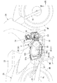
図1に示す自動二輪車(車両)1において、車体フレーム10の前端部に位置するヘッドパイプ11には、前輪WFを軸支する左右一対のフロントフォーク12がステム12aを介して操向可能に枢支される。ステム12aの上部には、転舵用のバーハンドル13が取り付けられる。   In the motorcycle (vehicle) 1 shown in FIG. 1, a pair of left and right front forks 12 that pivotally support the front wheel WF is pivotally supported via a stem 12 a on a head pipe 11 positioned at the front end of the body frame 10. Be supported. A bar handle 13 for steering is attached to the upper part of the stem 12a.

車体フレーム10は、ヘッドパイプ11から斜め下後方に一本のメインフレーム10aを延ばし、ヘッドパイプ11と乗員用のシート23との間を低床部として跨り易さを向上させた所謂低床バックボーン型とされる。メインフレーム10aの後端部にはピボットプレート10bが接合され、該ピボットプレート10bには後輪WRを軸支するスイングアーム15の前端部が揺動可能に枢支される。   The vehicle body frame 10 has a so-called low-floor backbone in which one main frame 10a extends obliquely downward and rearward from the head pipe 11 to improve straddling between the head pipe 11 and the occupant seat 23 as a low floor portion. A type. A pivot plate 10b is joined to a rear end portion of the main frame 10a, and a front end portion of a swing arm 15 that pivotally supports the rear wheel WR is pivotally supported on the pivot plate 10b.

メインフレーム10aの後部には、車体側面視で後上がりのクランク状をなす左右一対のシートフレーム10cの前端部が接合される。左右シートフレーム10cとスイングアーム15の左右アームとの間には、左右一対のリアクッション16が配置される。
車体フレーム10の中央下部内側(前記低床部内側)には、自動二輪車1の原動機であるエンジンEが搭載される。
The front end portions of a pair of left and right seat frames 10c that form a crank shape that rises rearward when viewed from the side of the vehicle body are joined to the rear portion of the main frame 10a. A pair of left and right rear cushions 16 are disposed between the left and right seat frames 10 c and the left and right arms of the swing arm 15.
An engine E that is a prime mover of the motorcycle 1 is mounted on the inner side of the lower part of the body frame 10 (the inner side of the low floor portion).

図2,3を併せて参照し、エンジンEは、エンジン本体30の右側にベルトコンバータ(ベルト式無段変速機、以下、単にベルコンということがある)100を一体に設けてなる。エンジン本体30は、車幅方向(左右方向)に沿うクランク軸を有する空冷単気筒エンジンであり、そのクランクケース31の前端部にやや前下がりの軸線に沿うシリンダ32を前方に突出させてなる。シリンダ32の先端(前端)に取り付くシリンダヘッド33の上方にはスロットルボディTHが配置され、該スロットルボディTHの上方にはエアクリーナケースACが配置される。シリンダヘッド33の下部から延びる排気管EXは、後方に湾曲して車体後部左側まで延びた後、後輪WRの左方に位置するサイレンサSLに接続される。   2 and 3 together, the engine E is integrally provided with a belt converter (belt type continuously variable transmission, hereinafter simply referred to as a velcon) 100 on the right side of the engine body 30. The engine main body 30 is an air-cooled single-cylinder engine having a crankshaft along the vehicle width direction (left-right direction), and a cylinder 32 along a slightly lowering axis is projected forward from the front end portion of the crankcase 31. A throttle body TH is disposed above the cylinder head 33 attached to the tip (front end) of the cylinder 32, and an air cleaner case AC is disposed above the throttle body TH. The exhaust pipe EX extending from the lower part of the cylinder head 33 is curved backward and extends to the left side of the rear part of the vehicle body, and then connected to a silencer SL located on the left side of the rear wheel WR.

エンジンEの車体フレーム10への搭載は、そのクランクケース31後端部の上下後マウント31a,31bがピボットプレート10bに支持されると共に、クランクケース31上端部の上マウント31cがメインフレーム10aから延びるハンガプレート10dに支持されることでなされる。
エンジンEの回転動力は、前記ベルコン100等を介してエンジン本体30後部左側のドライブスプロケット(エンジン出力部)18に出力された後、ドライブチェーン17を介して後輪WR左側のドリブンスプロケット19に伝達される。
When the engine E is mounted on the body frame 10, the upper and lower rear mounts 31a and 31b at the rear end of the crankcase 31 are supported by the pivot plate 10b, and the upper mount 31c at the upper end of the crankcase 31 extends from the main frame 10a. This is done by being supported by the hanger plate 10d.
Rotational power of the engine E is output to the drive sprocket (engine output unit) 18 on the left side of the rear portion of the engine body 30 through the Belcon 100 and the like, and then transmitted to the driven sprocket 19 on the left side of the rear wheel WR through the drive chain 17. Is done.

後輪WRの上方には燃料タンク20が配置され、該燃料タンク20の前方には荷物収容箱21が配置される。燃料タンク20及び荷物収容箱21はシート23下方に位置しており、該シート23がその前端下部のヒンジを介して開閉することで、燃料タンク20及び荷物収容箱21へのアクセスが可能となる。なお、図中符号MSは車体を直立状態で支持するメインスタンドを、符号SSは車体を左側に傾斜した起立状態で支持するサイドスタンドを、符号S1は運転者用のステップを、符号S2は後部同乗者用のステップをそれぞれ示す。   A fuel tank 20 is disposed above the rear wheel WR, and a luggage storage box 21 is disposed in front of the fuel tank 20. The fuel tank 20 and the luggage storage box 21 are located below the seat 23, and the seat 23 is opened and closed via a hinge at the lower part of the front end thereof, so that the fuel tank 20 and the luggage storage box 21 can be accessed. . In the figure, symbol MS indicates a main stand that supports the vehicle body in an upright state, symbol SS indicates a side stand that supports the vehicle body in an upright state inclined to the left side, symbol S1 indicates a step for the driver, and symbol S2 indicates rear riding. Each step is shown.

車体フレーム10の前部、エンジンEのシリンダ32及びシリンダヘッド33、並びにスロットルボディTH及びエアクリーナケースAC等は、合成樹脂製の前部車体カバー24により覆われる。前部車体カバー24は、運転者の脚部を前方からの風圧等から保護するレッグシールドを構成している。
また、車体フレーム10の後部、荷物収容箱21、及び燃料タンク20等は、同じく合成樹脂製の後部車体カバー25により覆われる。この後部車体カバー25は、シートフレーム10cと共にシート23を支持している。
The front part of the body frame 10, the cylinder 32 and the cylinder head 33 of the engine E, the throttle body TH, the air cleaner case AC, and the like are covered with a front body cover 24 made of synthetic resin. The front body cover 24 constitutes a leg shield that protects the driver's legs from wind pressure from the front.
The rear portion of the vehicle body frame 10, the luggage storage box 21, the fuel tank 20, and the like are also covered with a rear vehicle body cover 25 that is also made of synthetic resin. The rear body cover 25 supports the seat 23 together with the seat frame 10c.

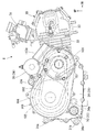
図3に示すように、ベルトコンバータ100は、ドライブプーリ101及びドリブンプーリ102にVベルト103を巻き掛けてなるもので、エンジン本体30におけるクランク軸の回転速度の変化に伴い、その回転動力に対する減速比を所定の範囲内で無段階に変化させる。このベルトコンバータ100が、エンジン側面視で前後に長い楕円状をなすベルコンケース104内に収容された状態で、クランクケース31右側に一体に取り付けられる。   As shown in FIG. 3, the belt converter 100 is formed by winding a V belt 103 around a drive pulley 101 and a driven pulley 102, and a deceleration with respect to the rotational power accompanying a change in the rotational speed of the crankshaft in the engine body 30. The ratio is changed steplessly within a predetermined range. The belt converter 100 is integrally attached to the right side of the crankcase 31 in a state of being accommodated in a bell-con case 104 having an elliptical shape that is long in the front-rear direction in a side view of the engine.

ドリブンプーリ102は、ドライブプーリ101の後方かつやや上方に位置し、かつドライブプーリ101よりもやや大径とされ、このドリブンプーリ102の前端とドライブプーリ101の後端とが互いに近接するように配置される。ベルコンケース104のプーリ収容部は、その前後端部の側面視形状が両プーリ101,102の外形に沿うように、やや後上がりかつ後部の上下幅をやや広げた楕円形状とされる。   The driven pulley 102 is positioned behind and slightly above the drive pulley 101 and has a slightly larger diameter than the drive pulley 101, and is arranged so that the front end of the driven pulley 102 and the rear end of the drive pulley 101 are close to each other. Is done. The pulley housing portion of the bell-con case 104 has an elliptical shape in which the shape of the front and rear end portions is slightly rearwardly raised and the rear portion is slightly widened so that the shape of the pulley in the side view conforms to the outer shapes of the pulleys 101 and 102.

ベルコンケース104のプーリ収容部におけるやや後上がりの下縁部は、クランクケース31におけるほぼ水平な下縁部よりも上方に位置しており、これら両下縁部間には、ベルコンケース104の下部右側壁34が右側方に面している。この下部右側壁34の後端部には、エンジンEのキックスタータ35における左右方向に沿うキックスピンドル36が配置される。キックスピンドル36は、ベルコンケース104のプーリ収容部における側面視円弧状の後端部の直ぐ下方、すなわち下部右側壁34が後上がりに広がった範囲を有効利用して配置されている。   The lower edge of the bellows case 104 that slightly rises rearward is positioned above the substantially horizontal lower edge of the crankcase 31, and the lower part of the bellcon case 104 is between these lower edges. The right wall 34 faces the right side. At the rear end of the lower right wall 34, a kick spindle 36 is disposed along the left-right direction of the kick starter 35 of the engine E. The kick spindle 36 is disposed by effectively utilizing a range where the lower right side wall 34 extends rearwardly, just below the rear end of the bell-concase 104 in the pulley accommodating portion in a side view arcuate shape.

図2を併せて参照し、キックスピンドル36は、車体側面視において、運転者用左ステップS1の後方かつやや下方に位置すると共に、シート23の運転者用着座部から下方に大きく離間して配置される。
キックスピンドル36の先端部は下部右側壁34から右方に突出し、該先端部にはキックペダル37の基端部が取り付けられる。キックペダル37における基端部から斜め上後方に延びるアームの先端部には、折り畳み式のペダル本体37aが取り付けられる。
Referring also to FIG. 2, the kick spindle 36 is located behind and slightly below the driver's left step S <b> 1 in a side view of the vehicle body, and is greatly spaced downward from the driver seating portion of the seat 23. Is done.
A tip end portion of the kick spindle 36 protrudes rightward from the lower right wall 34, and a base end portion of a kick pedal 37 is attached to the tip end portion. A foldable pedal body 37a is attached to the tip of the arm that extends obliquely upward and rearward from the base end of the kick pedal 37.

ペダル本体37aは、車体側面視でシート23の運転者用着座部から下方に適度に離間しており、このペダル本体37aを自動二輪車1に跨った運転者が踏み下ろした際には、該ペダル本体37aがキックスピンドル36を中心とした円弧に沿って概ね下方に移動する。これにより、自動二輪車1に跨った運転者がキックペダル37を自然に踏み下ろすことが可能である。
なお、エンジンEはセルフスタータ38も備えており、該セルフスタータ38のスタータモータ39が、クランクケース31の上部前側に配置される。また、クランクケース31の下部右側壁34におけるキックスピンドル36の直ぐ前方には、エンジンオイル用の点検窓34aが設けられる。
The pedal body 37a is moderately spaced downward from the seating portion for the driver of the seat 23 in a side view of the vehicle body. When the driver straddles the pedal body 37a over the motorcycle 1, the pedal body 37a The main body 37a moves substantially downward along an arc centered on the kick spindle 36. Thus, the driver straddling the motorcycle 1 can naturally depress the kick pedal 37.
The engine E also includes a self-starter 38, and a starter motor 39 of the self-starter 38 is disposed on the upper front side of the crankcase 31. An inspection window 34a for engine oil is provided in the lower right side wall 34 of the crankcase 31 immediately in front of the kick spindle 36.

図4に示すように、エンジン本体30のシリンダ32内には、その軸線に沿って摺動するピストン40が嵌装される。ピストン40には、左右方向に沿うピストンピン41を介してコンロッド42の小端部が揺動自在に連結され、該コンロッド42の大端部は、左右方向に沿うクランクピン43を介してクランク軸44に回転自在に連結される。クランク軸44は、クランクピン43を支持する左右クランクウェブ45の直ぐ外側にジャーナル46を有し、該両ジャーナル46が、クランクケース31の左右前側壁63a,64aにボールベアリング47を介して回転自在に支持される。なお、クランク軸44は、左右の分割体をクランクピン43を介して一体に結合した組み立て式とされる。   As shown in FIG. 4, a piston 40 that slides along its axis is fitted in the cylinder 32 of the engine body 30. A small end portion of a connecting rod 42 is swingably connected to the piston 40 via a piston pin 41 extending in the left-right direction, and a large end portion of the connecting rod 42 is connected to a crankshaft via a crank pin 43 extending in the left-right direction. 44 is rotatably connected. The crankshaft 44 has journals 46 immediately outside the left and right crank webs 45 that support the crankpins 43, and both journals 46 are freely rotatable on the left and right front side walls 63 a and 64 a of the crankcase 31 via ball bearings 47. Supported by The crankshaft 44 is an assembly type in which left and right divided bodies are integrally coupled via a crankpin 43.

左ジャーナル46の外側部は左方に比較的大きく延出し、その先端部にはシリンダ32外側よりも左右外側に位置するジェネレータ48のアウタロータ48aが同軸固定される。クランクケース31の左前側壁63aの外側には、右方に開口するカップ状のジェネレータカバー49が取り付けられ、該ジェネレータカバー49の内側にはジェネレータ48のステータコイル48bが支持され、該ステータコイル48bが前記アウタロータ48a内に配置される。なお、アウタロータ48aの右側には、前記スタータモータ39に連係するスタータドリブンギヤ39aがワンウェイクラッチを介して取り付けられる。   The outer portion of the left journal 46 extends to the left relatively large, and the outer rotor 48a of the generator 48 positioned on the left and right outside of the cylinder 32 outside is coaxially fixed to the tip thereof. A cup-shaped generator cover 49 that opens to the right is attached to the outside of the left front side wall 63a of the crankcase 31, and a stator coil 48b of the generator 48 is supported on the inside of the generator cover 49. It arrange | positions in the said outer rotor 48a. A starter driven gear 39a linked to the starter motor 39 is attached to the right side of the outer rotor 48a via a one-way clutch.

左ジャーナル46の左方には、シリンダヘッド33に支持される動弁機構50用の駆動スプロケット51が同軸固定されると共に、動弁機構50における左右方向に沿うカムシャフト52の左端には、駆動スプロケット51よりも大径の被動スプロケット53が同軸固定され、これら両スプロケットにカムチェーン54が巻き掛けられることで、クランクシャフトの回転動力により動弁機構50が駆動する。シリンダ32の左側には、カムチェーン54を通過させるカムチェーン室55が設けられている。   A drive sprocket 51 for the valve mechanism 50 supported by the cylinder head 33 is coaxially fixed to the left of the left journal 46, and at the left end of the camshaft 52 along the left-right direction in the valve mechanism 50, the drive sprocket 51 is driven. A driven sprocket 53 having a diameter larger than that of the sprocket 51 is coaxially fixed, and a cam chain 54 is wound around both the sprockets, so that the valve mechanism 50 is driven by the rotational power of the crankshaft. A cam chain chamber 55 through which the cam chain 54 passes is provided on the left side of the cylinder 32.

図6を併せて参照し、動弁機構50は、カムシャフト52の回転により、該カムシャフト52における吸排気用カムにそれぞれ摺接する二つのロッカーアーム56a,56bを揺動させ、これらがそれぞれ吸排気バルブ57a,57bを作動させてシリンダヘッド33の吸排気ポートを開閉させる。   Referring also to FIG. 6, the valve mechanism 50 causes the two rocker arms 56 a and 56 b slidably in contact with the intake and exhaust cams on the camshaft 52 by the rotation of the camshaft 52, respectively. The exhaust valves 57a and 57b are operated to open and close the intake and exhaust ports of the cylinder head 33.

右ジャーナル46の外側部は右方に比較的小さく延出し、該延出部にはプライマリドライブギヤ58が同軸固定される。プライマリドライブギヤ58は、クランク軸44の回転動力を出力可能とすると共に、前記キックスピンドル36のからの回転動力をクランク軸44に入力可能とするものである。プライマリドライブギヤ58は、後述のプライマリドリブンギヤ59と共に第一減速機構60を構成しており、該第一減速機構60、ベルトコンバータ100、及び後述の第二減速機構66を介して、クランク軸44の回転動力が前記ドライブスプロケット18に出力される。   The outer portion of the right journal 46 extends relatively small to the right, and a primary drive gear 58 is coaxially fixed to the extended portion. The primary drive gear 58 can output the rotational power of the crankshaft 44 and can input the rotational power from the kick spindle 36 to the crankshaft 44. The primary drive gear 58 constitutes a first reduction mechanism 60 together with a primary driven gear 59 described later, and the crankshaft 44 is connected to the primary drive gear 58 via the first reduction mechanism 60, the belt converter 100, and a second reduction mechanism 66 described later. Rotational power is output to the drive sprocket 18.

クランクケース31は、左右ケース半体をボルト等により一体に結合してなり、これら左右ケース半体が、左右ジャーナル46を支持する前記左右前側壁63a,64a、及びこれらに対して左側にオフセットした左右後側壁63b,64bをそれぞれ形成する。左前後側壁63a,63b及び右前後側壁64a,64bはそれぞれ一体に連なるもので、これらがケース左壁63及びケース右壁64を形成している。ケース右壁64の右方には前記ベルトコンバータ100が配置され、該ベルトコンバータ100を収容するベルコンケース104にケース右壁64が覆われる。   The crankcase 31 is formed by integrally joining the left and right case halves with bolts or the like, and the left and right case halves are offset to the left and right front side walls 63a and 64a that support the left and right journals 46 and to the left with respect thereto. Left and right rear side walls 63b and 64b are formed, respectively. The left front and rear side walls 63a and 63b and the right front and rear side walls 64a and 64b are integrally connected to each other, and form a case left wall 63 and a case right wall 64, respectively. The belt converter 100 is disposed on the right side of the case right wall 64, and the case right wall 64 is covered with a bell-con case 104 that accommodates the belt converter 100.

図5を併せて参照し、ベルコンケース104は、クランクケース31と同様、左右ケース半体をボルト等により一体に結合してなるもので、その左ケース半体がクランクケース31の右側部を覆っている。具体的には、左ケース半体は、右ケース半体における側面視楕円状のケース外壁108と対向するケース内壁107を形成すると共に、該ケース内壁107の下方に前記下部右側壁34を一体形成し、該下部右側壁34及びケース内壁107でクランクケース31の右側開口を閉塞している。   Referring also to FIG. 5, the bell-con case 104 is formed by integrally joining the left and right case halves with bolts or the like, like the crankcase 31, and the left case half covers the right side of the crankcase 31. ing. Specifically, the left case half forms a case inner wall 107 facing the oval case outer wall 108 in the right case half and the lower right side wall 34 is integrally formed below the case inner wall 107. The lower right side wall 34 and the case inner wall 107 close the right side opening of the crankcase 31.

また、ベルコンケース104の左ケース半体とクランクケース31との間に形成される空間K1は、クランクケース31内と連通して油室Yを構成し、該油室Y内には所定量のエンジンオイルが貯留される。すなわち、ベルコンケース104内は油室Y外である。
そして、エンジン本体30の駆動時には、後述のオイルポンプ80の作用により前記エンジンオイルが前記油室Y内及びシリンダヘッド33内の各部に供給される。シリンダヘッド33内に供給されたエンジンオイルは、前記カムチェーン室55及びジェネレータカバー49内を通じて油室Y内に戻される。
A space K1 formed between the left case half of the bell-con case 104 and the crankcase 31 communicates with the crankcase 31 to form an oil chamber Y. The oil chamber Y has a predetermined amount. Engine oil is stored. That is, the inside of the bell-con case 104 is outside the oil chamber Y.
When the engine main body 30 is driven, the engine oil is supplied to the oil chamber Y and the cylinder head 33 by the action of an oil pump 80 described later. The engine oil supplied into the cylinder head 33 is returned to the oil chamber Y through the cam chain chamber 55 and the generator cover 49.

ベルコンケース104内には、その前部にドライブプーリ101が、後部にドリブンプーリ102がそれぞれ配置され、これらがその中央部を貫通する左右方向に沿うドライブプーリ軸109及びドリブンプーリ軸110にそれぞれ支持される。
ここで、ドライブプーリ軸109は、クランク軸44(ジャーナル46)に対して前方(シリンダ32側)にオフセットして設けられ、エンジン側面視ではクランク軸44とシリンダ32の基端(後端)との間に位置している。換言すれば、エンジン側面視において、ドライブプーリ軸109とドリブンプーリ軸110との間にクランク軸44が位置している。さらに換言すれば、ドライブプーリ109は、クランク軸44を挟んでドリブンプーリ軸110と反対側にオフセットしている。
In the bell-con case 104, a drive pulley 101 is disposed at the front portion and a driven pulley 102 is disposed at the rear portion, and these are respectively supported by a drive pulley shaft 109 and a driven pulley shaft 110 extending in the left-right direction penetrating the center portion. Is done.
Here, the drive pulley shaft 109 is provided by being offset forward (cylinder 32 side) with respect to the crankshaft 44 (journal 46), and is viewed from the base end (rear end) of the crankshaft 44 and the cylinder 32 in a side view of the engine. Located between. In other words, the crankshaft 44 is positioned between the drive pulley shaft 109 and the driven pulley shaft 110 in a side view of the engine. In other words, the drive pulley 109 is offset to the opposite side of the driven pulley shaft 110 with the crankshaft 44 interposed therebetween.

そして、ドライブプーリ軸109の前方(シリンダ32側)へのオフセットに伴い、ドライブプーリ101が前方に移動することで、ドリブンプーリ102を前方に移動させることが可能となり、もってベルコン100全体を前方に移動させることが可能となる。これにより、エンジン側面視において、ベルトコンバータ100(ベルコンケース104)の後端位置をエンジン本体30の後端とほぼ同一位置に設定することが可能となる(図3参照)。   As the drive pulley 101 moves forward with the offset of the drive pulley shaft 109 forward (cylinder 32 side), the driven pulley 102 can be moved forward. It can be moved. As a result, the rear end position of the belt converter 100 (Belcon case 104) can be set to substantially the same position as the rear end of the engine body 30 in a side view of the engine (see FIG. 3).

また、ドライブプーリ101が前方へ移動することで、エンジン側面視において、その前端部(ベルコンケース104の前端部)がシリンダ32の基部(後部)とラップすることとなる(図3参照)。シリンダ32外周(及びシリンダヘッド33外周の一部)には、複数の冷却フィン32aが立設されており、前記ラップ部分においては、シリンダ32の冷却フィン32aの先端側が切り欠かれ、もってシリンダ32とベルコンケース104との間に空気流通用の空間K2が確保される。   Further, when the drive pulley 101 moves forward, the front end portion (front end portion of the bell-con case 104) wraps with the base portion (rear portion) of the cylinder 32 in a side view of the engine (see FIG. 3). A plurality of cooling fins 32a are provided upright on the outer periphery of the cylinder 32 (and a part of the outer periphery of the cylinder head 33), and the tip end side of the cooling fin 32a of the cylinder 32 is notched in the wrap portion, and thus the cylinder 32 is provided. And a space for air circulation K2 are secured between the bell-con case 104 and the bell-con case 104.

ドライブプーリ軸109の右端部は、ベルコンケース104のケース外壁108の前部(以下、外前側壁108aということがある)に外ボールベアリング109aを介して回転自在に支持される。また、ドライブプーリ軸109の左側部は、ベルコンケース104のケース内壁107の前部(以下、内前側壁107aということがある)を貫通すると共に該ケース内壁107に内ボールベアリング109bを介して回転自在に支持され、かつその左端部は、クランクケース31の右前側壁64aにニードルベアリング109cを介して回転自在に支持される。ドライブプーリ軸109の左端部は、右前側壁64aにおけるクランク軸44支持用の右ボールベアリング47の直ぐ前方に位置している。   The right end portion of the drive pulley shaft 109 is rotatably supported by a front portion of the case outer wall 108 of the bell-con case 104 (hereinafter also referred to as an outer front side wall 108a) via an outer ball bearing 109a. Further, the left side portion of the drive pulley shaft 109 passes through the front portion of the case inner wall 107 of the bell-con case 104 (hereinafter also referred to as the inner front side wall 107a) and rotates to the case inner wall 107 via the inner ball bearing 109b. The left end of the crankcase 31 is supported by the right front side wall 64a of the crankcase 31 via a needle bearing 109c. The left end portion of the drive pulley shaft 109 is positioned immediately in front of the right ball bearing 47 for supporting the crankshaft 44 on the right front side wall 64a.

ドライブプーリ軸109の左端部の直ぐ右側には、クランク軸44のプライマリドライブギヤ58に噛み合うプライマリドリブンギヤ59が同軸固定される。プライマリドリブンギヤ59はプライマリドライブギヤ58よりも大径であり、これら両ギヤ58,59により前記第一減速機構60が構成され、該第一減速機構60を介して、クランク軸44の回転動力が減速されつつドライブプーリ軸109に伝達される。   A primary driven gear 59 that meshes with the primary drive gear 58 of the crankshaft 44 is coaxially fixed to the right side of the left end portion of the drive pulley shaft 109. The primary driven gear 59 has a larger diameter than the primary drive gear 58, and the first reduction gear mechanism 60 is constituted by these gears 58, 59, and the rotational power of the crankshaft 44 is reduced via the first reduction gear mechanism 60. While being transmitted to the drive pulley shaft 109.

一方、ドリブンプーリ軸110は、ドライブプーリ軸109の後方かつやや上方に位置し、その右端部は、ベルコンケース104のケース外壁108の後部(以下、外後側壁108bということがある)に外ボールベアリング110aを介して回転自在に支持される。また、ドリブンプーリ軸110の左側部は、ケース内壁107の後部(以下、内後側壁107bということがある)を貫通した後、クランクケース31の右後側壁64bを貫通すると共に該右後側壁64bに内ボールベアリング110bを介して回転自在に支持され、かつその左端部は、クランクケース31の左後側壁63bに左ボールベアリング110cを介して回転自在に支持される。   On the other hand, the driven pulley shaft 110 is located at the rear and slightly above the drive pulley shaft 109, and the right end portion of the driven pulley shaft 110 is connected to the rear portion of the case outer wall 108 of the bell-con case 104 (hereinafter sometimes referred to as the outer rear side wall 108b). It is rotatably supported via a bearing 110a. Further, the left side portion of the driven pulley shaft 110 passes through the rear portion of the case inner wall 107 (hereinafter also referred to as the inner rear side wall 107b) and then passes through the right rear side wall 64b of the crankcase 31 and the right rear side wall 64b. The left end of the crankcase 31 is rotatably supported by the left rear side wall 63b via the left ball bearing 110c.

ドライブプーリ101は、ドライブプーリ軸109と一体回転可能に設けられるもので、ドライブプーリ軸109に対して固定される固定プーリ半体101aを左側に、ドライブプーリ軸109に対して軸方向で移動可能な可動プーリ半体101bを右側にそれぞれ配置してなる。各プーリ半体101a,101bは杯状をなし、その下端を向かい合わせるように配置されることで、両プーリ半体101a,101b間に周方向断面において外周側が広いV字状をなすV溝101cが形成される。   The drive pulley 101 is provided so as to be rotatable integrally with the drive pulley shaft 109, and the fixed pulley half 101 a fixed to the drive pulley shaft 109 can be moved in the axial direction with respect to the drive pulley shaft 109 on the left side. Each of the movable pulley halves 101b is arranged on the right side. The pulley halves 101a and 101b are cup-shaped and are arranged so that their lower ends face each other, so that a V-shaped groove 101c having a V-shaped outer peripheral side is wide in the circumferential cross section between the pulley halves 101a and 101b. Is formed.

一方、ドリブンプーリ102は、ドリブンプーリ軸110を挿通するスリーブ111を介して該ドリブンプーリ軸110と相対回転可能に設けられるもので、スリーブ111に対して固定される固定プーリ半体102aを右側に、スリーブ111に対して軸方向で移動可能な可動プーリ半体102bを左側にそれぞれ配置してなる。各プーリ半体102a,102bは杯状をなし、その下端を向かい合わせるように配置されることで、両プーリ半体102a,102b間に周方向断面において外周側が広いV字状をなすV溝102cが形成される。
そして、これら両プーリ101,102のV溝101c,102c内には、その傾斜面に整合する無端状のVベルト103が所定の張力をもって巻き掛けられる。
On the other hand, the driven pulley 102 is provided so as to be rotatable relative to the driven pulley shaft 110 via a sleeve 111 through which the driven pulley shaft 110 is inserted, and a fixed pulley half 102a fixed to the sleeve 111 is placed on the right side. The movable pulley half 102b that can move in the axial direction with respect to the sleeve 111 is arranged on the left side. The pulley halves 102a and 102b are cup-shaped and are arranged so that their lower ends face each other, so that a V-shaped groove 102c having a wide V-shaped outer peripheral side in the circumferential cross section between the pulley halves 102a and 102b. Is formed.
An endless V-belt 103 aligned with the inclined surface is wound around the V grooves 101c and 102c of both pulleys 101 and 102 with a predetermined tension.

ドライブプーリ101における可動プーリ半体101bは、右側すなわち固定プーリ半体101aから離間する側に付勢されると共に、該可動プーリ半体101bの内側(右側)には複数のウェイトローラ112が配設され、該ドライブプーリ101の回転停止時(クランク軸44の回転停止時)には、可動プーリ半体101bが固定プーリ半体101aから離間してV溝101cの左右幅を広げると共に、該V溝101cの内周側をVベルト103が巻回し、かつ可動プーリ半体101bの形状に沿って各ウェイトローラ112が内周側に案内される。   The movable pulley half 101b in the drive pulley 101 is urged to the right side, that is, the side away from the fixed pulley half 101a, and a plurality of weight rollers 112 are disposed on the inner side (right side) of the movable pulley half 101b. When the rotation of the drive pulley 101 is stopped (when the rotation of the crankshaft 44 is stopped), the movable pulley half 101b is separated from the fixed pulley half 101a to widen the left and right widths of the V groove 101c, and the V groove The V-belt 103 is wound around the inner peripheral side of 101c, and each weight roller 112 is guided to the inner peripheral side along the shape of the movable pulley half 101b.

そして、ドライブプーリ101の回転時(クランク軸44の回転時)において、その回転速度が所定値以上になると、各ウェイトローラ112に作用する遠心力の増加によりこれらが外周側へ徐々に移動すると共に、可動プーリ半体101bが付勢力に抗して左側に徐々に移動し、V溝101cの左右幅を狭めると共にVベルト103の巻回位置をドライブプーリ101の外周側に変化させる。なお、ドライブプーリ101の回転速度が減少すれば、前記回転停止時に戻るべく、各ウェイトローラ112が内周側へ徐々に移動すると共に、可動プーリ半体101bが右側に徐々に移動し、V溝101cの左右幅を広げてVベルト103の巻回位置を内周側に変化させる。   When the drive pulley 101 rotates (when the crankshaft 44 rotates), when the rotation speed exceeds a predetermined value, the centrifugal force acting on each weight roller 112 is gradually moved to the outer peripheral side. The movable pulley half 101b gradually moves to the left against the urging force, narrows the left and right width of the V groove 101c, and changes the winding position of the V belt 103 to the outer peripheral side of the drive pulley 101. If the rotational speed of the drive pulley 101 decreases, each weight roller 112 gradually moves to the inner peripheral side and the movable pulley half 101b gradually moves to the right side to return to the time when the rotation is stopped. The winding position of the V-belt 103 is changed to the inner peripheral side by widening the left and right width of 101c.

一方、ドリブンプーリ102における可動プーリ半体102bは、右側すなわち固定プーリ半体102aに近接する側に付勢されており、該ドリブンプーリ102の回転停止時(ドライブプーリ101の回転停止時)には、可動プーリ半体102bが固定プーリ半体102aに近接してV溝102cの左右幅を狭めると共に、両プーリ半体102a,102bの形状に沿って外周側に案内されたVベルト103がV溝102cの外周側を巻回する。   On the other hand, the movable pulley half 102b of the driven pulley 102 is urged to the right side, that is, the side close to the fixed pulley half 102a, and when the driven pulley 102 stops rotating (when the drive pulley 101 stops rotating). The movable pulley half 102b approaches the fixed pulley half 102a to narrow the left and right width of the V groove 102c, and the V belt 103 guided to the outer periphery along the shape of both pulley halves 102a and 102b The outer peripheral side of 102c is wound.

そして、ドリブンプーリ102の回転時(ドライブプーリ101の回転時)において、前述の如くドライブプーリ101におけるVベルト103の巻回位置が外周側へ変化すると、Vベルト103の長さは一定であることから、該Vベルト103がドリブンプーリ102のV溝102cの左右幅を広げるべく可動プーリ半体102bを付勢力に抗して左側に徐々に移動させつつ、その巻回位置を内周側に変化させる。なお、ドリブンプーリ102の回転速度が減少すれば、前記回転停止時に戻るべく、可動プーリ半体102bが右側に徐々に移動し、V溝102cの左右幅を狭めてVベルト103の巻回位置を内周側に変化させる。   When the driven pulley 102 rotates (when the drive pulley 101 rotates), if the winding position of the V belt 103 in the drive pulley 101 changes to the outer peripheral side as described above, the length of the V belt 103 is constant. Thus, the V belt 103 gradually moves the movable pulley half 102b to the left against the urging force so as to widen the left and right width of the V groove 102c of the driven pulley 102, and its winding position changes to the inner peripheral side. Let If the rotational speed of the driven pulley 102 decreases, the movable pulley half 102b gradually moves to the right side to return to the stoppage of rotation, narrowing the left and right width of the V groove 102c and setting the winding position of the V belt 103. Change to the inner circumference.

このように、クランク軸44の回転速度すなわちエンジン本体30の回転数の増減に伴い、ドライブプーリ101におけるVベルト103の巻き掛け径とドリブンプーリ102におけるVベルト103の巻き掛け径とが反比例しつつ徐々に変化することで、クランク軸44の回転動力に対する減速比が自動的かつ連続的に変化し、エンジン回転数に応じた滑らかな無段階変速が可能となる。   Thus, as the rotational speed of the crankshaft 44, that is, the rotational speed of the engine body 30 increases or decreases, the winding diameter of the V belt 103 in the drive pulley 101 and the winding diameter of the V belt 103 in the driven pulley 102 are inversely proportional. By gradually changing, the reduction ratio with respect to the rotational power of the crankshaft 44 is automatically and continuously changed, and a smooth stepless speed change according to the engine speed becomes possible.

ドライブプーリ101における固定プーリ半体101aの内側には冷却ファン113が構成され、該冷却ファン113がドライブプーリ101と共に回転することで、ベルコンケース104の前部上側の吸気口113a(図3参照)からベルコンケース104内に外気が導入され、該ベルコンケース104内に配置されたベルトコンバータ100等が強制冷却される。   A cooling fan 113 is formed inside the fixed pulley half 101a of the drive pulley 101, and the cooling fan 113 rotates together with the drive pulley 101, so that an intake port 113a on the front upper side of the bell-con case 104 (see FIG. 3). Then, outside air is introduced into the bell-con case 104, and the belt converter 100 and the like disposed in the bell-con case 104 are forcibly cooled.

ドリブンプーリ102の左方には、スリーブ111とドリブンプーリ軸110との間の動力伝達を断続する遠心クラッチ114が設けられる。遠心クラッチ114は、可動プーリ半体102bと対向するように配置されてドリブンプーリ軸110に同軸固定されるカップ状のクラッチアウタ114aと、該クラッチアウタ114a内の底部側(左側)に配置されてスリーブ111に同軸固定される円板状のインナプレート114bと、該インナプレート114bの外周部右側に拡径作動可能に取り付けられる複数のシュー114cとを有してなる。   A centrifugal clutch 114 is provided on the left side of the driven pulley 102 to intermittently transmit power between the sleeve 111 and the driven pulley shaft 110. The centrifugal clutch 114 is disposed so as to face the movable pulley half 102b and is coaxially fixed to the driven pulley shaft 110. The centrifugal clutch 114 is disposed on the bottom side (left side) of the clutch outer 114a. A disc-shaped inner plate 114b coaxially fixed to the sleeve 111 and a plurality of shoes 114c attached to the right side of the outer peripheral portion of the inner plate 114b so as to be capable of expanding the diameter.

各シュー114cは縮径方向に付勢されており、これらがドリブンプーリ102の回転速度が所定値以下の場合にクラッチアウタ114aから離間することで、インナプレート114bとクラッチアウタ114aとを相対回転可能とし、スリーブ111とドリブンプーリ軸110との間の動力伝達を遮断する。そして、ドリブンプーリ102の回転速度が所定値を超えた場合には、各シュー114cに作用する遠心力の増加によりこれらが拡径作動してクラッチアウタ114aに摩擦係合し、インナプレート114bとクラッチアウタ114aとを一体回転可能とし、スリーブ111とドリブンプーリ軸110との間の動力伝達を可能としてドリブンプーリ軸110を駆動させる。   Each shoe 114c is urged in the diameter reducing direction, and when the rotational speed of the driven pulley 102 is equal to or lower than a predetermined value, the inner plate 114b and the clutch outer 114a can be rotated relative to each other by being separated from the clutch outer 114a. The power transmission between the sleeve 111 and the driven pulley shaft 110 is cut off. When the rotational speed of the driven pulley 102 exceeds a predetermined value, the centrifugal force acting on each shoe 114c increases to increase the diameter of the driven pulley 102 and frictionally engage the clutch outer 114a. The outer 114a can be rotated integrally, and power transmission between the sleeve 111 and the driven pulley shaft 110 is enabled to drive the driven pulley shaft 110.

ベルコンケース104の内前側壁107aは、その左方に第一減速機構60及び後述のオイルポンプ80用の駆動ギヤ81を配置可能とするべく、クランクケース31の右前側壁64aから所定量離間して設けられる。ここで、第一減速機構60及びオイルポンプ駆動ギヤ81は、クランクケース31の右前側壁64aの外側(左側)に位置しており、クランクケース31を左右分割することなくベルコンケース104を取り外すのみで外部に露出させることが可能である。   The inner front side wall 107a of the bell-con case 104 is separated from the right front side wall 64a of the crankcase 31 by a predetermined amount so that the first reduction mechanism 60 and a drive gear 81 for an oil pump 80 described later can be arranged on the left side. Provided. Here, the first reduction mechanism 60 and the oil pump drive gear 81 are located on the outside (left side) of the right front side wall 64a of the crankcase 31, and only the bellcon case 104 is removed without dividing the crankcase 31 into left and right. It can be exposed to the outside.

また、ベルコンケース104の内後側壁107bは、その右方に遠心クラッチ114を配置可能とするべく左方に凸の杯状に膨出形成される。なお、内後側壁107bの杯形状は、遠心クラッチ114のクラッチアウタ114aの底部形状に対応したものである。クランクケース31の右後側壁64bは左側にオフセットしていることから、該右後側壁64bとベルコンケース104の内後側壁107bとが所定量離間して設けられる。   Further, the inner rear side wall 107b of the bell-con case 104 is bulged and formed in a cup shape protruding leftward so that the centrifugal clutch 114 can be disposed on the right side. The cup shape of the inner rear side wall 107b corresponds to the bottom shape of the clutch outer 114a of the centrifugal clutch 114. Since the right rear side wall 64b of the crankcase 31 is offset to the left side, the right rear side wall 64b and the inner rear side wall 107b of the bell-con case 104 are spaced apart by a predetermined amount.

このように、ベルコンケース104のケース内壁107とクランクケース31のケース右壁64とが適宜離間することで、前記空間K1が形成される。
ベルコンケース104の外前側壁108aは、その後方の外後側壁108bが概ね平坦に形成されるのに対し、ドライブプーリ101における可動プーリ半体101bの移動代を確保するべく、右方に凸の半球状に膨出形成されている。
As described above, the space K1 is formed by appropriately separating the case inner wall 107 of the bell-con case 104 and the case right wall 64 of the crankcase 31 from each other.
The outer front side wall 108a of the bell-con case 104 has a substantially flat rear rear side wall 108b, whereas the outer front side wall 108b has a convex shape to the right in order to secure a moving margin of the movable pulley half 101b in the drive pulley 101. A hemispherical bulge is formed.

ドリブンプーリ軸110に伝達された回転動力は、第二減速機構66を介してさらに減速された後、エンジンEにおける出力軸に伝達される。
第二減速機構66は、二軸に振り分けられた複数の減速ギヤ群で構成され、こられがドライブプーリ軸109の左側部であるメインシャフト67、及び該メインシャフト67の斜め下後方に配される左右方向に沿うカウンタシャフト68にそれぞれ貫通支持される。
The rotational power transmitted to the driven pulley shaft 110 is further decelerated via the second reduction mechanism 66 and then transmitted to the output shaft in the engine E.
The second reduction mechanism 66 includes a plurality of reduction gear groups distributed on two axes, and these are arranged on the main shaft 67 that is the left side of the drive pulley shaft 109, and obliquely below and behind the main shaft 67. Are respectively supported by the countershaft 68 along the horizontal direction.

カウンタシャフト68は、その両側部がクランクケース31の左右後側壁63b,64bを貫通すると共に、該左右後側壁63b,64bに左右ボールベアリング68a,68bを介して回転自在に支持される。カウンタシャフト68の左端部は、クランクケース31外に突出して前記出力軸を構成し、該カウンタシャフト68の左端部に前記ドライブスプロケット18が取り付けられる。   Both sides of the counter shaft 68 penetrate the left and right rear side walls 63b and 64b of the crankcase 31, and are rotatably supported by the left and right rear side walls 63b and 64b via left and right ball bearings 68a and 68b. The left end portion of the counter shaft 68 protrudes outside the crankcase 31 to constitute the output shaft, and the drive sprocket 18 is attached to the left end portion of the counter shaft 68.

第二減速機構66は、メインシャフト67(ドリブンプーリ軸110)における左ボールベアリング110cの直ぐ右方に同軸固定される第一ギヤ69と、カウンタシャフト68における左ボールベアリング68aの直ぐ右方に同軸かつ相対回転自在に支持される第二ギヤ70と、メインシャフト67における第一ギヤ69と内ボールベアリング110bとの間に同軸かつ相対回転自在に支持される第三ギヤ71と、カウンタシャフト68における第二ギヤ70と右ボールベアリング68bとの間に同軸固定される第四ギヤ72とからなる。   The second speed reduction mechanism 66 is coaxially fixed to the right side of the left ball bearing 68a on the counter shaft 68 and the first gear 69 fixed coaxially to the right side of the left ball bearing 110c on the main shaft 67 (driven pulley shaft 110). And a second gear 70 supported in a relatively rotatable manner, a third gear 71 supported in a coaxial and relatively rotatable manner between the first gear 69 and the inner ball bearing 110 b in the main shaft 67, and a counter shaft 68. The fourth gear 72 is coaxially fixed between the second gear 70 and the right ball bearing 68b.

第二ギヤ70は、第一ギヤ69よりも大径かつこれに噛み合う大径第二ギヤ70aと、その右側に隣接する比較的小径の小径第二ギヤ70bとを一体に設けた親子ギヤとされる。また、第三ギヤ71は、小径第二ギヤ70bよりも大径かつこれに噛み合う大径第三ギヤ71aと、その右側に隣接する比較的小径の小径第三ギヤ71bとを一体に設けた親子ギヤとされる。小径第三ギヤ71bは、これよりも大径の第四ギヤ72に噛み合っており、メインシャフト67に伝達された回転動力は、各ギヤ69〜72間で順次減速されつつカウンタシャフト68に伝達される。すなわち、比較的小型の第二減速機構66において、比較的大きな減速比を設定することが可能である。   The second gear 70 is a parent-child gear in which a large-diameter second gear 70a having a larger diameter than the first gear 69 and meshing with the first gear 69 and a relatively small-diameter small-diameter second gear 70b adjacent to the right side thereof are integrally provided. The The third gear 71 has a larger diameter than the small-diameter second gear 70b and meshes with the large-diameter third gear 71a, and a parent and child integrally provided with a relatively small-diameter small-diameter third gear 71b adjacent to the right side thereof. It is assumed to be a gear. The small-diameter third gear 71b meshes with the fourth gear 72 having a larger diameter than this, and the rotational power transmitted to the main shaft 67 is transmitted to the countershaft 68 while being sequentially decelerated between the gears 69-72. The That is, it is possible to set a relatively large reduction ratio in the relatively small second reduction mechanism 66.

ドライブプーリ軸109におけるプライマリドリブンギヤ59と内ボールベアリング109bとの間には、オイルポンプ80用の駆動ギヤ81が同軸固定される。
駆動ギヤ81は、プライマリドリブンギヤ59よりも小径のもので、第一減速機構60の下方に位置するオイルポンプ80の回転軸上の被動ギヤ82に噛み合い、ドライブプーリ軸109の回転に伴いオイルポンプ80を駆動させる。オイルポンプ80駆動時には、油室Y内下部に貯留されたエンジンオイルがストレーナを介して吸引されると共に、該エンジンオイルがベルコンケース104の内前側壁107aに形成された油路及びこれに連通するべくクランク軸44に形成された油路等を通じてエンジン本体30内に圧送され、前述の如くエンジン本体30内を適宜循環する。
A drive gear 81 for the oil pump 80 is coaxially fixed between the primary driven gear 59 and the inner ball bearing 109 b in the drive pulley shaft 109.
The drive gear 81 has a smaller diameter than the primary driven gear 59, meshes with the driven gear 82 on the rotation shaft of the oil pump 80 located below the first reduction mechanism 60, and the oil pump 80 is rotated with the rotation of the drive pulley shaft 109. Drive. When the oil pump 80 is driven, the engine oil stored in the lower portion of the oil chamber Y is sucked through the strainer, and the engine oil communicates with the oil passage formed on the inner front side wall 107a of the bell-con case 104 and the oil passage. Therefore, it is pumped into the engine body 30 through an oil passage formed in the crankshaft 44 and circulates through the engine body 30 as described above.

クランクケース31の下部右側壁34の後端部には、キックスピンドル36の右側部を支持するハブ部36aが形成される。ハブ部36aはベルコンケース104の後端部の略真下において左右に延在し、該ハブ部36aから右方に突出するキックスピンドル36の先端部(右端部)に前記キックペダル37の基端部が取り付けられる。キックスピンドル36の左側部は、その中間部がクランクケース31における中支持壁36bに支持されると共に、左端部がクランクケース31における左支持壁36cに支持される。中支持壁36bとハブ部36aとの間には、キックスピンドル36を貫通させるリターンスプリング74が配置され、中支持壁36bと左支持壁36cとの間には、キックスピンドル36と同軸のキックドライブギヤ75及び噛み合い機構75aが配置される。   A hub portion 36 a that supports the right side portion of the kick spindle 36 is formed at the rear end portion of the lower right side wall 34 of the crankcase 31. The hub portion 36a extends to the left and right substantially directly below the rear end portion of the bell-con case 104, and the base end portion of the kick pedal 37 extends to the tip end portion (right end portion) of the kick spindle 36 that projects rightward from the hub portion 36a. Is attached. The left portion of the kick spindle 36 is supported by the middle support wall 36 b in the crankcase 31 and the left end portion is supported by the left support wall 36 c in the crankcase 31. A return spring 74 that passes through the kick spindle 36 is disposed between the middle support wall 36b and the hub portion 36a, and a kick drive coaxial with the kick spindle 36 is disposed between the middle support wall 36b and the left support wall 36c. A gear 75 and a meshing mechanism 75a are disposed.

キックドライブギヤ75は、キックペダル37の踏み込みに応じたキックスピンドル36の一方向への相対回転時にのみ、噛み合い機構75aの作動によりキックスピンドル36に相対回転不能に係合する。また、キックドライブギヤ75は、キックペダル37が戻る際やエンジン始動後等、キックスピンドル36の前記一方向に対する逆方向への相対回転時には、キックスピンドル36に対して相対回転自在となる。キックドライブギヤ75、噛み合い機構75a、及びリターンスプリング74、並びに各支持壁36b,36c及びハブ部36aとキックスピンドル36との摺動部は、クランクケース31の油室Y内に臨んでいる。   The kick drive gear 75 is engaged with the kick spindle 36 so as not to rotate relative to the kick spindle 36 only by relative rotation in one direction of the kick spindle 36 in response to the depression of the kick pedal 37. The kick drive gear 75 is rotatable relative to the kick spindle 36 when the kick spindle 37 is rotated relative to the one direction opposite to the one direction, such as when the kick pedal 37 returns or after the engine is started. The kick drive gear 75, the meshing mechanism 75 a, the return spring 74, the support walls 36 b and 36 c, the sliding portion between the hub portion 36 a and the kick spindle 36 face the oil chamber Y of the crankcase 31.

そして、キックペダル37の踏み込みによりキックスピンドル36に生じた回転動力は、噛み合い機構75a及びキックドライブギヤ75、キックアイドルギヤ76、キックドリブンギヤ77、及びプライマリドライブギヤ58を介してクランク軸44に伝達される。
キックアイドルギヤ76は、キックドライブギヤ75よりも大径とされてこれに噛み合うもので、前記空間K1内において第二減速機構66のカウンタシャフト68と同軸配置され、該カウンタシャフト68におけるクランクケース31の右後側壁64bから右方に突出する右端部に相対回転自在に支持される。
The rotational power generated in the kick spindle 36 by the depression of the kick pedal 37 is transmitted to the crankshaft 44 via the meshing mechanism 75a and the kick drive gear 75, the kick idle gear 76, the kick driven gear 77, and the primary drive gear 58. The
The kick idle gear 76 has a larger diameter than the kick drive gear 75 and meshes with the kick drive gear 75. The kick idle gear 76 is coaxially arranged with the counter shaft 68 of the second reduction mechanism 66 in the space K1. Of the right rear side wall 64b of the right end of the right end of the right end portion of the right rear wall 64b.

キックドリブンギヤ77は、キックアイドルギヤ76よりも小径とされてこれに噛み合う小径ドリブンギヤ77aと、該小径ドリブンギヤ77aよりも大径とされてプライマリドライブギヤ58に噛み合う大径ドリブンギヤ77bとを一体に設けた親子ギヤとされ、前記空間K1内において第二減速機構66のメインシャフト67と同軸配置されてこれに相対回転自在に支持される。小径ドリブンギヤ77aはメインシャフト67支持用の内ボールベアリング110bの直ぐ右方に位置し、該小径ドリブンギヤ77aの右側に隣接して大径ドリブンギヤ77bが一体に設けられる。   The kick driven gear 77 is integrally provided with a small diameter driven gear 77a that has a smaller diameter than the kick idle gear 76 and meshes with the kick idle gear 76, and a large diameter driven gear 77b that has a larger diameter than the small diameter driven gear 77a and meshes with the primary drive gear 58. It is a parent-child gear, and is coaxially arranged with the main shaft 67 of the second reduction mechanism 66 in the space K1, and is supported by the main shaft 67 so as to be relatively rotatable. The small diameter driven gear 77a is located immediately to the right of the inner ball bearing 110b for supporting the main shaft 67, and the large diameter driven gear 77b is integrally provided adjacent to the right side of the small diameter driven gear 77a.

大径ドリブンギヤ77bは、小径ドリブンギヤ77aとの外径差を広げるべく比較的大型のギヤとして構成される。このような大径ドリブンギヤ77bは、ベルコンケース104の内後側壁107bに沿う杯状をなし、前記空間K1内に効率良く配置されている。
これら各ギヤ75,76,77,58間において、キックスピンドル36からの回転動力が加減速を繰り返しつつ、最終的には加速された状態でクランク軸44に伝達される。
The large diameter driven gear 77b is configured as a relatively large gear in order to widen the outer diameter difference from the small diameter driven gear 77a. Such a large-diameter driven gear 77b has a cup shape along the inner rear side wall 107b of the bell-con case 104, and is efficiently arranged in the space K1.
Between these gears 75, 76, 77, and 58, the rotational power from the kick spindle 36 is transmitted to the crankshaft 44 in an accelerated state while repeating acceleration and deceleration.

キックドライブギヤ75、噛み合い機構75a、キックアイドルギヤ76、キックドリブンギヤ77、及びプライマリドライブギヤ58からなるキック伝動機構78は、クランクケース31の油室Y内に配置されることで、エンジンオイルによる潤滑が可能であると共に、第一減速機構60と同様、ベルコンケース104を取り外すのみで外部に露出させることが可能である。   The kick transmission mechanism 78 including the kick drive gear 75, the meshing mechanism 75a, the kick idle gear 76, the kick driven gear 77, and the primary drive gear 58 is disposed in the oil chamber Y of the crankcase 31, thereby being lubricated by engine oil. As with the first speed reduction mechanism 60, it is possible to expose the bell-con case 104 only by removing it.

以上説明したように、上記実施例におけるエンジンEは、ドライブプーリ101及びドリブンプーリ102にVベルト103を巻き掛けてなるベルトコンバータ100を介して、エンジン本体30のクランク軸44の回転動力を伝達するものであって、前記クランク軸44の前方(シリンダ32側)にオフセットしてドライブプーリ軸109を配置したものであり、換言すれば、ドライブプーリ軸109とドリブンプーリ軸110との間にクランク軸44を配置したものである。   As described above, the engine E in the above embodiment transmits the rotational power of the crankshaft 44 of the engine body 30 via the belt converter 100 in which the V belt 103 is wound around the drive pulley 101 and the driven pulley 102. In other words, the drive pulley shaft 109 is disposed offset to the front (cylinder 32 side) of the crankshaft 44, in other words, the crankshaft between the drive pulley shaft 109 and the driven pulley shaft 110. 44 is arranged.

この構成によれば、クランク軸44の左右端を避けてドライブプーリ軸109が配置されることで、ドライブプーリ101がクランク軸44の側方へ張り出し難くなり、エンジンEの左右幅を抑えることができる。また、ドライブプーリ101と共にドリブンプーリ102が前方(シリンダ32側)へ移動することで、ベルコン100の後端位置がエンジン本体30の後端位置から後方へはみ出し難くなり、エンジンEの前後長を抑えることができる。そして、このようにエンジンEの外形寸法を抑えることで、該エンジンEの車体フレーム10への搭載性を向上させることができる。   According to this configuration, the drive pulley shaft 109 is disposed so as to avoid the left and right ends of the crankshaft 44, so that the drive pulley 101 does not easily protrude to the side of the crankshaft 44, and the left and right width of the engine E can be suppressed. it can. Further, when the driven pulley 102 moves forward (cylinder 32 side) together with the drive pulley 101, it becomes difficult for the rear end position of the bell-con 100 to protrude rearward from the rear end position of the engine body 30, and the longitudinal length of the engine E is suppressed. be able to. And by suppressing the outer dimension of the engine E in this way, the mountability of the engine E on the vehicle body frame 10 can be improved.

また、上記エンジンEにおいては、前記ベルトコンバータ100を前記エンジン本体30の右側に設けると共に、該ベルトコンバータ100の下方にキックスピンドル36を設けたことで、車体に跨った乗員がキックし易い位置にキックスピンドル36が配置されることとなり、キックスタータ35の使い勝手を向上させることができる。   Further, in the engine E, the belt converter 100 is provided on the right side of the engine body 30 and the kick spindle 36 is provided below the belt converter 100, so that an occupant straddling the vehicle body can easily kick. The kick spindle 36 is arranged, and the usability of the kick starter 35 can be improved.

さらに、上記エンジンEにおいては、前記クランク軸44とドライブプーリ軸109との間に第一減速機構60を設け、該第一減速機構60をクランクケース31とベルコンケース104とで囲ったことで、エンジン本体30からベルコンケース104を着脱することのみで、第一減速機構60を外部に露出させることが可能となり、メンテナンス性を向上させることができる。また、ベルコンケース104が第一減速機構60のカバーを兼ねることで、エンジンEの部品点数削減による重量及びコストの低減を図ることができる。   Further, in the engine E, the first reduction mechanism 60 is provided between the crankshaft 44 and the drive pulley shaft 109, and the first reduction mechanism 60 is surrounded by the crankcase 31 and the bellcon case 104, The first reduction mechanism 60 can be exposed to the outside only by attaching / detaching the bell-con case 104 to / from the engine main body 30, and the maintainability can be improved. Further, since the bell-con case 104 also serves as a cover for the first reduction mechanism 60, the weight and cost can be reduced by reducing the number of parts of the engine E.

さらにまた、上記エンジンEにおいては、前記ドライブプーリ軸109における前記第一減速機構60とドライブプーリ101との間に、オイルポンプ80用の駆動ギヤ81を設けたことで、クランク軸44にオイルポンプ用の駆動ギヤを設ける場合と比べて、エンジンEの左右幅をさらに抑えることができる。   Furthermore, in the engine E, a drive gear 81 for the oil pump 80 is provided between the first speed reduction mechanism 60 and the drive pulley 101 on the drive pulley shaft 109, so that the oil pump on the crankshaft 44 is provided. Compared with the case where the drive gear for this is provided, the left-right width of the engine E can be further suppressed.

また、上記エンジンEにおいては、エンジン側面視で前記シリンダ32とドライブプーリ101とがラップすることで、エンジン側面視における外形寸法をさらに抑えることができる。   Further, in the engine E, the cylinder 32 and the drive pulley 101 wrap when viewed from the side of the engine, so that the outer dimension when viewed from the side of the engine can be further suppressed.

しかも、上記エンジンEにおいては、前記シリンダ32とドライブプーリ101とのラップ部分におけるシリンダ32とベルコンケース104との間に空間K2を設けたことで、シリンダ32周りの空気流通路が確保されるため、エンジンEの冷却性を向上させることができる。   Moreover, in the engine E, since the space K2 is provided between the cylinder 32 and the bell-con case 104 at the lap portion between the cylinder 32 and the drive pulley 101, an air flow passage around the cylinder 32 is secured. The cooling performance of the engine E can be improved.

この発明の実施例における自動二輪車の左側面図である。1 is a left side view of a motorcycle according to an embodiment of the present invention. 上記自動二輪車のエンジン周辺の右側面図である。Fig. 2 is a right side view around the engine of the motorcycle. 上記エンジンの右側面図である。It is a right view of the said engine. 上記エンジンのエンジン本体の展開断面図である。It is an expanded sectional view of the engine main part of the above-mentioned engine. 上記エンジンのベルトコンバータの展開断面図である。It is an expanded sectional view of the belt converter of the above-mentioned engine. 上記エンジンからベルトコンバータを取り外した際の右側面図である。It is a right view at the time of removing a belt converter from the engine.

符号の説明Explanation of symbols

1 自動二輪車(車両)
E エンジン
30 エンジン本体
31 クランクケース
32 シリンダ
36 キックスピンドル
44 クランク軸
60 第一減速機構(減速機構)
80 オイルポンプ
81 駆動ギヤ
100 ベルトコンバータ(ベルト式無段変速機)
101 ドライブプーリ
102 ドリブンプーリ
103 Vベルト
104 ベルコンケース
109 ドライブプーリ軸
110 ドリブンプーリ軸
K2 空間

1 Motorcycle (vehicle)
E Engine 30 Engine body 31 Crankcase 32 Cylinder 36 Kick spindle 44 Crankshaft 60 First reduction mechanism (deceleration mechanism)
80 Oil pump 81 Drive gear 100 Belt converter (belt type continuously variable transmission)
101 Drive Pulley 102 Driven Pulley 103 V Belt 104 Velcon Case 109 Drive Pulley Shaft 110 Driven Pulley Shaft K2 Space

Claims (5)

ドライブプーリ(101)及びドリブンプーリ(102)にVベルト(103)を巻き掛けてなるベルト式無段変速機(100)を介して、エンジン本体(30)のクランク軸(44)の回転動力を伝達するベルト式無段変速機(100)を備えたエンジン(E)において、
前記クランク軸(44)よりシリンダ(32)側にオフセットしてドライブプーリ軸(109)を配置し、エンジン(E)側面視で前記シリンダ(32)とドライブプーリ(101)とがラップすることを特徴とするベルト式無段変速機を備えたエンジン。
The rotational power of the crankshaft (44) of the engine body (30) is transmitted via a belt-type continuously variable transmission (100) in which a V-belt (103) is wound around a drive pulley (101) and a driven pulley (102). In an engine (E) provided with a belt-type continuously variable transmission (100) for transmission,
The drive pulley shaft (109) is disposed offset from the crankshaft (44) toward the cylinder (32), and the cylinder (32) and the drive pulley (101) are wrapped when viewed from the side of the engine (E). An engine with a belt type continuously variable transmission.
前記ベルト式無段変速機(100)を前記エンジン本体(30)の一側に設けると共に、該ベルト式無段変速機(100)の下方にキックスピンドル(36)を設けたことを特徴とする請求項1に記載のベルト式無段変速機を備えたエンジン。   The belt type continuously variable transmission (100) is provided on one side of the engine body (30), and a kick spindle (36) is provided below the belt type continuously variable transmission (100). An engine comprising the belt-type continuously variable transmission according to claim 1. 前記クランク軸(44)とドライブプーリ軸(109)との間に減速機構(60)を設け、該減速機構(60)をクランクケース(31)とベルコンケース(104)とで囲ったことを特徴とする請求項1又は請求項2に記載のベルト式無段変速機を備えたエンジン。   A reduction mechanism (60) is provided between the crankshaft (44) and the drive pulley shaft (109), and the reduction mechanism (60) is surrounded by a crankcase (31) and a bellcon case (104). An engine comprising the belt-type continuously variable transmission according to claim 1 or 2. 前記ドライブプーリ軸(109)における前記減速機構(60)とドライブプーリ(101)との間に、オイルポンプ(80)用の駆動ギヤ(81)を設けたことを特徴とする請求項3に記載のベルト式無段変速機を備えたエンジン。   The drive gear (81) for the oil pump (80) is provided between the speed reduction mechanism (60) and the drive pulley (101) on the drive pulley shaft (109). An engine equipped with a belt-type continuously variable transmission. 前記シリンダ(32)とドライブプーリ(109)とのラップ部分におけるシリンダ(32)とベルコンケース(104)との間に空間(K2)を設けたことを特徴とする請求項1に記載のベルト式無段変速機を備えたエンジン。The belt type according to claim 1, wherein a space (K2) is provided between the cylinder (32) and the bell-con case (104) in a lap portion between the cylinder (32) and the drive pulley (109). An engine with a continuously variable transmission.
JP2005345236A 2005-11-30 2005-11-30 Engine with belt type continuously variable transmission Expired - Fee Related JP4772479B2 (en)

Priority Applications (2)

Application Number Priority Date Filing Date Title
JP2005345236A JP4772479B2 (en) 2005-11-30 2005-11-30 Engine with belt type continuously variable transmission
CN200610162439A CN100594295C (en) 2005-11-30 2006-11-22 Engine with belt type stepless transmission

Applications Claiming Priority (1)

Application Number Priority Date Filing Date Title
JP2005345236A JP4772479B2 (en) 2005-11-30 2005-11-30 Engine with belt type continuously variable transmission

Publications (3)

Publication Number Publication Date
JP2007146801A JP2007146801A (en) 2007-06-14
JP2007146801A5 JP2007146801A5 (en) 2008-11-27
JP4772479B2 true JP4772479B2 (en) 2011-09-14

Family

ID=38125419

Family Applications (1)

Application Number Title Priority Date Filing Date
JP2005345236A Expired - Fee Related JP4772479B2 (en) 2005-11-30 2005-11-30 Engine with belt type continuously variable transmission

Country Status (2)

Country Link
JP (1) JP4772479B2 (en)
CN (1) CN100594295C (en)

Families Citing this family (3)

* Cited by examiner, † Cited by third party
Publication number Priority date Publication date Assignee Title
JP5162400B2 (en) * 2008-09-30 2013-03-13 本田技研工業株式会社 Internal combustion engine
JP5303340B2 (en) 2009-03-31 2013-10-02 本田技研工業株式会社 Internal combustion engine with kick starter
JP5417080B2 (en) * 2009-08-03 2014-02-12 本田技研工業株式会社 Auxiliary arrangement structure of power unit for vehicle

Family Cites Families (11)

* Cited by examiner, † Cited by third party
Publication number Priority date Publication date Assignee Title
JPS5986748A (en) * 1982-11-10 1984-05-19 Honda Motor Co Ltd Belt type power transmission device
JP2609525B2 (en) * 1987-07-13 1997-05-14 ヤマハ発動機株式会社 Vehicle drive system
JP2657062B2 (en) * 1987-09-10 1997-09-24 ヤマハ発動機株式会社 Transmissions for motorcycles and tricycles
JP4437564B2 (en) * 1998-05-21 2010-03-24 ヤマハ発動機株式会社 Engine with V-belt continuously variable transmission
JP4282845B2 (en) * 1999-10-08 2009-06-24 本田技研工業株式会社 Power unit for vehicle
JP3788155B2 (en) * 2000-01-11 2006-06-21 スズキ株式会社 Small vehicle engine unit
JP2002097917A (en) * 2000-09-21 2002-04-05 Suzuki Motor Corp Engine unit for vehicle
JP2002266653A (en) * 2001-03-09 2002-09-18 Yamaha Motor Co Ltd Snow vehicle
JP4055469B2 (en) * 2002-05-20 2008-03-05 スズキ株式会社 Power unit casing structure
JP4318924B2 (en) * 2003-01-15 2009-08-26 本田技研工業株式会社 Power unit for motorcycles and tricycles
WO2005007499A1 (en) * 2003-07-16 2005-01-27 Yamaha Hatsudoki Kabushiki Kaisha Engine for saddle-riding type vehicle and saddle-riding type vehicle having the same

Also Published As

Publication number Publication date
JP2007146801A (en) 2007-06-14
CN1975127A (en) 2007-06-06
CN100594295C (en) 2010-03-17

Similar Documents

Publication Publication Date Title
JP3709973B2 (en) Belt-type transmission
US20080156563A1 (en) Power unit for a motorcycle, and motorcycle incorporating same
JP4879156B2 (en) Power transmission device for vehicle
JP4772479B2 (en) Engine with belt type continuously variable transmission
JP5314290B2 (en) Vehicle power unit
JP4522944B2 (en) Engine kick starter with belt-type continuously variable transmission
JP4889588B2 (en) Power unit
JP2009243288A (en) Power unit
JP5047746B2 (en) Power unit for small vehicles
JP2009030714A (en) Cooling structure of belt type continuously variable transmission
JP4975547B2 (en) Power unit transmission case cover
JP4627067B2 (en) Motorcycle
JP2008190424A (en) Decompression device for internal combustion engine
JP2008024163A (en) Sensor cover structure
JP2007177689A (en) Power unit
JP4781335B2 (en) On-vehicle power unit
JP5227922B2 (en) Torque damper device for saddle-ride type vehicles
JP5303340B2 (en) Internal combustion engine with kick starter
JP4879579B2 (en) Power unit for vehicle
JPH1181934A (en) Valve spring seat structure for internal combustion engine
JP5436005B2 (en) Transmission air guide structure
JP6033908B2 (en) V belt type continuously variable transmission
JP2017180344A (en) Power unit for saddle type vehicle with kick starter
JP2011169182A (en) Valve gear for engine
JP5687136B2 (en) Power unit for small vehicles

Legal Events

Date Code Title Description
A521 Written amendment

Free format text: JAPANESE INTERMEDIATE CODE: A523

Effective date: 20081009

A621 Written request for application examination

Free format text: JAPANESE INTERMEDIATE CODE: A621

Effective date: 20081009

A977 Report on retrieval

Free format text: JAPANESE INTERMEDIATE CODE: A971007

Effective date: 20101207

A131 Notification of reasons for refusal

Free format text: JAPANESE INTERMEDIATE CODE: A131

Effective date: 20101214

A521 Written amendment

Free format text: JAPANESE INTERMEDIATE CODE: A523

Effective date: 20110207

TRDD Decision of grant or rejection written
A01 Written decision to grant a patent or to grant a registration (utility model)

Free format text: JAPANESE INTERMEDIATE CODE: A01

Effective date: 20110614

A01 Written decision to grant a patent or to grant a registration (utility model)

Free format text: JAPANESE INTERMEDIATE CODE: A01

A61 First payment of annual fees (during grant procedure)

Free format text: JAPANESE INTERMEDIATE CODE: A61

Effective date: 20110622

FPAY Renewal fee payment (event date is renewal date of database)

Free format text: PAYMENT UNTIL: 20140701

Year of fee payment: 3

R150 Certificate of patent or registration of utility model

Free format text: JAPANESE INTERMEDIATE CODE: R150

LAPS Cancellation because of no payment of annual fees