JP4772001B2 - Vibration isolator with thermal barrier rubber cover - Google Patents
Vibration isolator with thermal barrier rubber cover Download PDFInfo
- Publication number
- JP4772001B2 JP4772001B2 JP2007184971A JP2007184971A JP4772001B2 JP 4772001 B2 JP4772001 B2 JP 4772001B2 JP 2007184971 A JP2007184971 A JP 2007184971A JP 2007184971 A JP2007184971 A JP 2007184971A JP 4772001 B2 JP4772001 B2 JP 4772001B2
- Authority
- JP
- Japan
- Prior art keywords
- rubber cover
- stopper
- central
- plate portion
- heat insulating
- Prior art date
- Legal status (The legal status is an assumption and is not a legal conclusion. Google has not performed a legal analysis and makes no representation as to the accuracy of the status listed.)
- Expired - Fee Related
Links
Images


Classifications
-
- F—MECHANICAL ENGINEERING; LIGHTING; HEATING; WEAPONS; BLASTING
- F16—ENGINEERING ELEMENTS AND UNITS; GENERAL MEASURES FOR PRODUCING AND MAINTAINING EFFECTIVE FUNCTIONING OF MACHINES OR INSTALLATIONS; THERMAL INSULATION IN GENERAL
- F16F—SPRINGS; SHOCK-ABSORBERS; MEANS FOR DAMPING VIBRATION
- F16F1/00—Springs
- F16F1/36—Springs made of rubber or other material having high internal friction, e.g. thermoplastic elastomers
- F16F1/371—Springs made of rubber or other material having high internal friction, e.g. thermoplastic elastomers characterised by inserts or auxiliary extension or exterior elements, e.g. for rigidification
- F16F1/3713—Springs made of rubber or other material having high internal friction, e.g. thermoplastic elastomers characterised by inserts or auxiliary extension or exterior elements, e.g. for rigidification with external elements passively influencing spring stiffness, e.g. rings or hoops
-
- F—MECHANICAL ENGINEERING; LIGHTING; HEATING; WEAPONS; BLASTING
- F16—ENGINEERING ELEMENTS AND UNITS; GENERAL MEASURES FOR PRODUCING AND MAINTAINING EFFECTIVE FUNCTIONING OF MACHINES OR INSTALLATIONS; THERMAL INSULATION IN GENERAL
- F16F—SPRINGS; SHOCK-ABSORBERS; MEANS FOR DAMPING VIBRATION
- F16F2230/00—Purpose; Design features
- F16F2230/0052—Physically guiding or influencing
- F16F2230/007—Physically guiding or influencing with, or used as an end stop or buffer; Limiting excessive axial separation
-
- F—MECHANICAL ENGINEERING; LIGHTING; HEATING; WEAPONS; BLASTING
- F16—ENGINEERING ELEMENTS AND UNITS; GENERAL MEASURES FOR PRODUCING AND MAINTAINING EFFECTIVE FUNCTIONING OF MACHINES OR INSTALLATIONS; THERMAL INSULATION IN GENERAL
- F16F—SPRINGS; SHOCK-ABSORBERS; MEANS FOR DAMPING VIBRATION
- F16F2230/00—Purpose; Design features
- F16F2230/48—Thermal insulation
Landscapes
- Engineering & Computer Science (AREA)
- General Engineering & Computer Science (AREA)
- Mechanical Engineering (AREA)
- Arrangement Or Mounting Of Propulsion Units For Vehicles (AREA)
- Combined Devices Of Dampers And Springs (AREA)
- Vibration Prevention Devices (AREA)
Description
本発明は、防振連結される一方の部材に取り付けられる第一の取付部材と他方の部材に取り付けられる第二の取付部材を本体ゴム弾性体で弾性連結した防振装置に係り、特に、第一の取付部材と第二の取付部材が相互に離隔する方向の変位量を制限するリバウンドストッパ機構と、本体ゴム弾性体への熱の影響を抑える遮熱ゴムカバーとを備えた、新規な構造の遮熱ゴムカバー付き防振装置に関するものである。 The present invention relates to an anti-vibration device in which a first attachment member attached to one member to be anti-vibrated and a second attachment member attached to the other member are elastically connected by a main rubber elastic body. A novel structure comprising a rebound stopper mechanism that limits the amount of displacement in the direction in which the one mounting member and the second mounting member are separated from each other, and a heat shield rubber cover that suppresses the effect of heat on the rubber elastic body The present invention relates to a vibration isolator with a heat insulating rubber cover.
従来から、振動伝達系を構成する部材間に介装される防振連結体や防振支持体等の防振装置の一種として、防振連結される一方の部材に取り付けられる第一の取付部材と他方の部材に取り付けられる第二の取付部材を本体ゴム弾性体で連結した構造のものが知られている。かかる構造の防振装置では、例えば、自動車用のエンジンマウントやボデーマウント、サスペンションブッシュ等への適用が検討されている。 Conventionally, as a type of anti-vibration device such as an anti-vibration coupling body and an anti-vibration support body interposed between members constituting the vibration transmission system, a first mounting member attached to one member to be anti-vibration connected And the thing of the structure which connected the 2nd attachment member attached to the other member with the main body rubber elastic body is known. In the vibration isolator having such a structure, for example, application to an engine mount, a body mount, a suspension bush, etc. for automobiles is being studied.
ところで、防振装置において良好な振動絶縁効果を得るには、ばね特性が十分に柔らかいことが望ましい。一方、大きな振動荷重が入力された際に、防振連結される一方の部材と他方の部材の大きな変位を抑えることが必要となる。そこで、防振装置には、第一の取付部材と第二の取付部材に対して相対的な変位量を制限するストッパ機構を設けることが多い。 By the way, in order to obtain a good vibration insulation effect in the vibration isolator, it is desirable that the spring characteristics are sufficiently soft. On the other hand, when a large vibration load is input, it is necessary to suppress a large displacement between one member and the other member that are connected in a vibration-proof manner. Therefore, the vibration isolator is often provided with a stopper mechanism that limits the amount of displacement relative to the first mounting member and the second mounting member.
このようなストッパ機構の一種として、特許文献1(特開2005−172202号公報)にも示されているように、門形のストッパ部材の両脚部分を第一の取付部材を軸直角方向に跨いで第二の取付部材に固定せしめ、ストッパ部材の中央部分と第一の取付部材を軸方向で対向位置せしめたリバウンド型のストッパ機構がある。これによれば、大荷重入力により第一の取付部材と第二の取付部材が相互に離隔する方向(リバウンド方向)に大きく変位して、ストッパ部材が第一の取付部材に打ち当たることで、第一及び第二の取付部材のリバウンド方向の変位量が制限されるようになっている。 As a kind of such a stopper mechanism, as shown in Patent Document 1 (Japanese Patent Application Laid-Open No. 2005-172202), both leg portions of a gate-shaped stopper member straddle a first mounting member in a direction perpendicular to the axis. There is a rebound type stopper mechanism that is fixed to the second mounting member and the central portion of the stopper member and the first mounting member are opposed to each other in the axial direction. According to this, by the large load input, the first mounting member and the second mounting member are greatly displaced in the direction separating from each other (rebound direction), the stopper member hits the first mounting member, The amount of displacement of the first and second attachment members in the rebound direction is limited.
ところで、上述のストッパ機構を備えた防振装置は、例えば大振幅振動が入力される自動車用エンジンマウント等に適用される場合が多い。そこで、本体ゴム弾性体が内燃機関の輻射熱や熱気等に直接に晒されると、耐久性能の低下により、ゴム弾性体本来の弾性による防振効果が十分に得られ難い問題があった。 By the way, an anti-vibration device having the above-described stopper mechanism is often applied to, for example, an automobile engine mount to which large amplitude vibration is input. Therefore, when the main rubber elastic body is directly exposed to radiant heat, hot air, etc. of the internal combustion engine, there is a problem that it is difficult to sufficiently obtain a vibration-proofing effect due to the inherent elasticity of the rubber elastic body due to a decrease in durability.
かかる問題に対処するための方策の一つとして、本体ゴム弾性体の外面を離隔して覆うように遮熱カバー(遮熱板)を配設し、本体ゴム弾性体の外部熱の影響を抑えるようにした、遮熱カバー付きの防振装置が知られている。例えば、特許文献2(特開2004−276764号公報)に示されるものが、それである。 As one of the measures for coping with this problem, a heat shield cover (heat shield plate) is provided so as to cover the outer surface of the main rubber elastic body so as to be separated, thereby suppressing the influence of external heat of the main rubber elastic body. Such a vibration isolator with a heat insulating cover is known. For example, it is what is shown by patent document 2 (Unexamined-Japanese-Patent No. 2004-276762).
しかしながら、特許文献2に示される防振装置では、遮熱カバーの中央部分が本体ゴム弾性体とストッパ部材の間を通って第一の取付部材に支持されていると共に、遮熱カバーの外周部分が、ストッパ部材の外周部分が固定されたのと同じ第二の取付部材側のブラケットに支持された構造を呈していることから、遮熱カバーを防振装置本体に位置決めして固定する組み付け作業が複雑になり、また組み付け工数の削減が図られ難いこともあって、製造効率の向上が達成され難い問題を内在していた。 However, in the vibration isolator shown in Patent Document 2, the center portion of the heat shield cover is supported by the first mounting member through the main rubber elastic body and the stopper member, and the outer peripheral portion of the heat shield cover. However, since the outer peripheral portion of the stopper member is supported by the same bracket on the side of the second mounting member, the assembly work for positioning and fixing the heat insulating cover to the vibration isolator body However, since it is difficult to reduce the number of assembly steps, there is a problem that it is difficult to improve the manufacturing efficiency.
本発明は上述の如き事情を背景として為されたものであって、その解決課題とするところは、ストッパ機構を備えた防振装置において、遮熱ゴムカバーが防振装置本体に速やかに且つ確実に組み付けられることによって、目的とする遮熱効果が安定して得られると共に、製造効率が有利に向上され得る、新規な構造の遮熱ゴムカバー付き防振装置を提供することにある。 The present invention has been made in the background as described above, and the problem to be solved is that in a vibration isolator having a stopper mechanism, a heat insulating rubber cover is quickly and reliably attached to the vibration isolator body. As a result, it is an object of the present invention to provide a vibration isolator with a heat insulating rubber cover having a novel structure, in which a desired heat insulating effect can be stably obtained and manufacturing efficiency can be advantageously improved.
以下、このような課題を解決するために為された本発明の態様を記載する。なお、以下に記載の各態様において採用される構成要素は、可能な限り任意の組み合わせで採用可能である。また、本発明の態様乃至は技術的特徴は、以下に記載のものに限定されることなく、明細書全体および図面に記載され、或いはそれらの記載から当業者が把握することの出来る発明思想に基づいて認識されるものであることが理解されるべきである。 Hereinafter, the aspect of this invention made | formed in order to solve such a subject is described. In addition, the component employ | adopted in each aspect as described below is employable by arbitrary combinations as much as possible. In addition, aspects or technical features of the present invention are not limited to those described below, but are described in the entire specification and drawings, or can be understood by those skilled in the art from those descriptions. It should be understood that it is recognized on the basis of.
すなわち、本発明の特徴とするところは、防振連結される一方の部材に取り付けられる第一の取付部材と防振連結される他方の部材に取り付けられる第二の取付部材を本体ゴム弾性体で連結する一方、軸直角方向に延びる当接板部の両端に一対の脚部を備えた門形状のストッパ部材を用いて、一対の脚部の下端を第二の取付部材に固定して第一の取付部材から外方に突出するようにしてストッパ部材を組み付けることにより当接板部と第一の取付部材を対向位置せしめて、当接板部と第一の取付部材が当接することによって第一の取付部材と第二の取付部材の互いに離隔する方向の変位量を制限するリバウンドストッパ機構を構成すると共に、本体ゴム弾性体の外面を離隔して覆う遮熱ゴムカバーを第一の取付部材側から本体ゴム弾性体に被せるように配設した遮熱ゴムカバー付き防振装置において、ストッパ部材における当接板部と一対の脚部に、それぞれ外方に開口する係止凹溝を形成すると共に、当接板部の係止凹溝の両側壁部には高さ方向先端部分に切欠状の段差部を設ける一方、遮熱ゴムカバーの中央部分の外面に中央爪部を一体形成すると共に遮熱ゴムカバーの周壁部分の外面に外側爪部を一体形成して、当接板部における係止凹溝の両側壁部に中央爪部を係止すると共に、一対の脚部における係止凹溝の両側壁部に外側爪部を係止し、更に、当接板部における係止凹溝の両側壁部に設けた段差部の両端段差面に対して中央爪部の両端面を当接させることにより遮熱ゴムカバーの中央部分をストッパ部材の当接板部に対して係止凹溝の長手方向で位置決めして、遮熱ゴムカバーをストッパ部材に固定した遮熱ゴムカバー付き防振装置にある。 That is, a feature of the present invention is that the first attachment member attached to one member to be anti-vibration connected and the second attachment member attached to the other member to be anti-vibration connected are made of a main rubber elastic body. The lower end of the pair of legs is fixed to the second mounting member using a portal-shaped stopper member having a pair of legs on both ends of the contact plate extending in the direction perpendicular to the axis. By assembling the stopper member so as to protrude outward from the mounting member, the abutting plate portion and the first mounting member are opposed to each other, and the abutting plate portion and the first mounting member abut on each other. The first mounting member comprises a rebound stopper mechanism that limits the amount of displacement in the direction in which the one mounting member and the second mounting member are spaced apart from each other, and the thermal insulation rubber cover that covers and separates the outer surface of the main rubber elastic body Cover the rubber elastic body from the side In the vibration isolator with the thermal insulation rubber cover arranged as described above, the contact plate portion and the pair of leg portions of the stopper member are respectively formed with locking concave grooves that open outward, and the contact plate portion On both side walls of the locking groove, a notch-shaped step is provided at the tip in the height direction, while a central claw portion is integrally formed on the outer surface of the center portion of the heat shield rubber cover and the peripheral wall portion of the heat shield rubber cover The outer claws are integrally formed on the outer surface of the contact plate, and the central claws are locked to the both side walls of the locking groove in the contact plate portion, and the outer side walls are external to the locking grooves in the pair of legs. The heat insulating rubber cover is configured by locking the claw portion and further bringing both end surfaces of the central claw portion into contact with both step surfaces of the step portion provided on both side walls of the locking groove in the contact plate portion. The central portion of the heat shield is positioned with respect to the contact plate portion of the stopper member in the longitudinal direction of the locking groove. Is the cover thermal barrier rubber covered vibration isolator fixed to the stopper member.
このような本発明に従う構造とされた遮熱ゴムカバー付き防振装置においては、遮熱ゴムカバーの中央爪部がストッパ部材における当接板部の係止凹溝の両側壁部に係止されることで、遮熱ゴムカバーの中央部分が、門形のストッパ部材の当接板部が設けられた中央部分に支持される。また、遮熱ゴムカバーの外側爪部がストッパ部材における各脚部の係止凹溝の両側壁部に係止されることで、遮熱ゴムカバーの周壁部分が、ストッパ部材の各脚部が設けられた外周部分に支持される。それによって、遮熱ゴムカバーが、ストッパ部材を介して、第一及び第二の取付部材が本体ゴム弾性体で弾性連結されてなる防振装置本体に固定されるようになっている。 In the vibration isolator with the heat insulating rubber cover having such a structure according to the present invention, the central claw portion of the heat insulating rubber cover is locked to the both side walls of the locking groove of the contact plate portion of the stopper member. Thus, the central portion of the heat insulating rubber cover is supported by the central portion provided with the contact plate portion of the gate-shaped stopper member. Further, the outer claw portion of the heat shield rubber cover is locked to the both side walls of the locking groove of each leg portion of the stopper member, so that the peripheral wall portion of the heat shield rubber cover is fixed to each leg portion of the stopper member. It is supported by the provided outer peripheral part. Accordingly, the heat insulating rubber cover is fixed to the vibration isolator main body in which the first and second mounting members are elastically connected by the main rubber elastic body via the stopper member.
ここで、ストッパ部材と遮熱ゴムカバーが互いに別体形成されていることにより、ストッパ部材と遮熱ゴムカバーの形状や大きさ、配置等の設計自由度が互いに大きく干渉することが抑えられる。その結果、要求される遮熱効果に応じて、遮熱ゴムカバーの設計変更が有利に為される。 Here, since the stopper member and the heat insulating rubber cover are formed separately from each other, it is possible to prevent the design freedom of the shape, size, arrangement, and the like of the stopper member and the heat insulating rubber cover from greatly interfering with each other. As a result, the design change of the heat insulating rubber cover is advantageously made according to the required heat insulating effect.
また、中央爪部や外側爪部が遮熱ゴムカバーと一体形成されていることによって、これらの爪部を弾性変形させつつ、ストッパ部材の係止凹溝に係止することが可能となり、組み付け作業が容易となる。 In addition, since the central claw part and the outer claw part are integrally formed with the heat-insulating rubber cover, it is possible to lock the claw part in the locking groove of the stopper member while elastically deforming the claw part. Work becomes easy.
特に、中央爪部の当接板部への位置決めは、当接板部の係止凹溝の両側壁部に設けられた段差部に中央爪部が入り込んだ状態とされて、係止凹溝の長手方向の両側において、中央爪部の両端面が段差部の両端段差面に対して対向位置せしめられる。そして、中央爪部の両端面が段差部の両端段差面に当接することによって、中央爪部の当接板部に対する相対変位が、係止凹溝の長手方向で拘束されることとなって位置決め効果が発揮される。かかる中央爪部の位置決めに伴い、遮熱ゴムカバーの外側爪部も固定すべきストッパ部材の脚部に対して安定して位置決めされることとなる。これにより、遮熱ゴムカバーのストッパ部材を介した防振装置本体に対する位置決めが、簡単な構造で効果的に実現されることとなり、位置ずれに起因する遮熱ゴムカバーのストッパ部材からの外れも防止される。 In particular, the positioning of the central claw portion to the abutment plate portion is such that the central claw portion enters the stepped portion provided on both side walls of the engagement ditch groove of the abutment plate portion. On both sides in the longitudinal direction, both end surfaces of the central claw portion are positioned opposite to both end step surfaces of the step portion. The relative displacement of the central claw portion with respect to the abutting plate portion is restricted in the longitudinal direction of the locking groove by positioning the both end surfaces of the central claw portion on both end step surfaces of the step portion. The effect is demonstrated. With the positioning of the central claw portion, the outer claw portion of the heat-insulating rubber cover is also stably positioned with respect to the leg portion of the stopper member to be fixed. As a result, positioning of the heat insulating rubber cover with respect to the vibration isolator main body via the stopper member is effectively realized with a simple structure, and the heat insulating rubber cover is also detached from the stopper member due to misalignment. Is prevented.
なお、中央爪部の両端面における段差部の両端段差面に対する当接状態は、遮熱ゴムカバーのストッパ部材への装着状態下で常時設定されている必要はなく、例えば、係止凹溝の長手方向において中央爪部の長さ寸法を段差部の長さ寸法よりも小さく設定して、該中央爪部の一方の端面又は両方の端面が段差部の端部段差面に対して所定の距離を隔てて対向位置せしめ、遮熱ゴムカバーがストッパ部材に対して係止凹溝の長手方向で所定距離だけ相対変位した場合にだけ、中央爪部の端面が段差部の端部段差面に当接してそれ以上の変位を阻止し得るようになっていても良い。尤も、常時、中央爪部の両端面が段差部の両端段差面に対して当接した状態で組み付けられることにより、遮熱ゴムカバーのストッパ部材に対する位置決め効果が一層確実に発揮されることとなる。そして、ゴム弾性体からなる中央爪部と外側爪部でストッパ部材に確実に係止されていることに加えて、かくの如く中央爪部の端面と係止凹溝の壁部の段差面の当接状態が保持されることによって、遮熱ゴムカバーの防振装置本体に対する位置ずれが一層効果的に抑えられる。 It should be noted that the contact state of the stepped portion with respect to the both end stepped surfaces at the both end surfaces of the central claw portion does not need to be always set in a state where the heat insulating rubber cover is attached to the stopper member. The length dimension of the central claw portion is set to be smaller than the length dimension of the step portion in the longitudinal direction, and one end surface or both end surfaces of the central claw portion is a predetermined distance from the end step surface of the step portion. The end face of the central claw part contacts the end step surface of the step part only when the heat shield rubber cover is relatively displaced by a predetermined distance in the longitudinal direction of the locking groove with respect to the stopper member. Further displacement may be prevented by contact. However, by assembling in a state where both end faces of the central claw portion are always in contact with both end step faces of the stepped portion, the positioning effect of the heat insulating rubber cover on the stopper member is more reliably exhibited. . In addition to being securely locked to the stopper member by the central claw portion and the outer claw portion made of a rubber elastic body, the step surface of the end surface of the central claw portion and the wall portion of the locking groove is thus made. By maintaining the contact state, the displacement of the heat insulating rubber cover relative to the vibration isolator body can be more effectively suppressed.
従って、本構造の遮熱ゴムカバー付き防振装置においては、遮熱ゴムカバーがストッパ部材を利用して、部品点数の増加を伴うことなく、防振装置本体に容易に組み付けられることから、製造効率の向上や低コスト化が有利に達成され得るのであり、しかも、遮熱ゴムカバーの防振装置本体に対する位置決めが確実とされ且つ安定して保持されることによって、遮熱ゴムカバーと本体ゴム弾性体の外面との離隔距離が高度に設定、保持されて、所期の遮熱効果が有利に発揮され得るのである。 Therefore, in the vibration isolator with the heat insulating rubber cover of this structure, the heat insulating rubber cover can be easily assembled to the vibration isolator main body without increasing the number of parts by using the stopper member. Efficiency improvement and cost reduction can be advantageously achieved, and the thermal insulation rubber cover and the main body rubber are secured by stably positioning the thermal insulation rubber cover with respect to the vibration isolator main body. The separation distance from the outer surface of the elastic body is set and maintained at a high level, and the desired heat shielding effect can be advantageously exhibited.
また、本発明に係る遮熱ゴムカバー付き防振装置では、遮熱ゴムカバーが逆カップ形状を有しており、遮熱ゴムカバーの外面には底部から両周壁部に亘って延びる嵌入凹所を形成して、嵌入凹所の中央部分の壁部に中央爪部を形成すると共に、嵌入凹所の中央部分から端部側に偏倚した壁部に外側爪部を形成して、嵌入凹所にストッパ部材を嵌め込んだ構造が、採用されても良い。このような構造によれば、嵌入凹所による嵌合構造を利用して、遮熱ゴムカバーがストッパ部材に一層安定して支持されると共に、高度な位置決めが実現される。 Further, in the vibration isolator with the heat insulating rubber cover according to the present invention, the heat insulating rubber cover has an inverted cup shape, and the outer surface of the heat insulating rubber cover has an insertion recess extending from the bottom portion to both peripheral wall portions. Forming a central claw portion on the wall portion of the central portion of the insertion recess, and forming an outer claw portion on the wall portion biased from the central portion of the insertion recess toward the end portion, A structure in which a stopper member is fitted in may be employed. According to such a structure, the heat shielding rubber cover is more stably supported by the stopper member and a high degree of positioning is realized using the fitting structure by the fitting recess.
また、本発明に係る遮熱ゴムカバー付き防振装置では、中央爪部や外側爪部を、嵌入凹所の壁部上端から幅方向内側に延びる横壁部と横壁部の内側端部から嵌入凹所の底部に向かって延びる縦壁部を含んで構成して、ストッパ部材の係止凹溝の上端部分を横壁部および縦壁部の内側に嵌め込むことで、中央爪部や外側爪部を係止凹溝の両壁部に係止した構造が、採用されても良い。このような構造によれば、爪部が係止凹溝の壁部に巻き込まれるようにして係止されることとなり、係止構造の安定が一層有利に図られ得る。 Further, in the vibration isolator with the thermal insulation rubber cover according to the present invention, the central claw portion and the outer claw portion are inserted into the insertion recesses from the lateral wall portion extending inward in the width direction from the wall portion upper end of the insertion recess portion and the inner end portion of the lateral wall portion. A vertical wall portion extending toward the bottom of the center portion, and by fitting the upper end portion of the locking groove of the stopper member inside the horizontal wall portion and the vertical wall portion, the central claw portion and the outer claw portion can be A structure locked to both wall portions of the locking groove may be employed. According to such a structure, the claw portion is locked so as to be caught in the wall portion of the locking groove, so that the locking structure can be more stably stabilized.
さらに、上述の本発明に係る遮熱ゴムカバー付き防振装置では、縦壁部を横壁部に比して厚肉とした構造が、好適に採用される。このような構造によれば、係止凹溝の壁部を縦壁部で軸直角方向に挟み込む力が好適に得られて、遮熱ゴムカバーの支持安定性が有利に向上され得る。また、遮熱ゴムカバーの加硫成形時や爪部を係止凹溝の壁部に組み付けた際に、縦壁部のめくれ上がりが好適に抑えられる。また、横壁部は縦壁部に比して薄肉とされているため、爪部の弾性変形作用が好適に確保され、縦壁部の厚肉化に起因する遮熱ゴムカバーのストッパ部材への組み付け作業の悪化が有利に防止され得る。 Furthermore, in the vibration isolator with the thermal insulation rubber cover which concerns on the above-mentioned this invention, the structure which made the vertical wall part thick compared with a horizontal wall part is employ | adopted suitably. According to such a structure, the force which pinches | interposes the wall part of a latching ditch | groove in an axial perpendicular direction with a vertical wall part is obtained suitably, and the support stability of a heat insulation rubber cover can be improved advantageously. Further, when the heat shield rubber cover is vulcanized or when the claw portion is assembled to the wall portion of the locking groove, the vertical wall portion can be suitably prevented from turning up. Further, since the horizontal wall portion is thinner than the vertical wall portion, the elastic deformation action of the claw portion is suitably secured, and the heat insulating rubber cover due to the thickening of the vertical wall portion is applied to the stopper member. Deterioration of the assembly work can be advantageously prevented.
更にまた、上述の本発明に係る遮熱ゴムカバー付き防振装置では、縦壁部の先端部分を嵌入凹所の底部に向かって薄肉となる先細り形状とした構造が、好適に採用される。このような構造によれば、縦壁部の先端部分が、ストッパ部材の係止凹溝の壁部における当接板部や脚部の基端部分に当たることが軽減乃至は回避され、組み付け作業の容易化や組み付け状態の安定性の更なる向上が図られ得る。 Furthermore, in the above-described vibration isolator with a heat insulating rubber cover according to the present invention, a structure in which the tip portion of the vertical wall portion is tapered toward the bottom portion of the insertion recess is preferably employed. According to such a structure, it is reduced or avoided that the front end portion of the vertical wall portion hits the contact plate portion or the base end portion of the leg portion in the wall portion of the locking groove of the stopper member. It is possible to further facilitate and further improve the stability of the assembled state.
また、本発明に係る遮熱ゴムカバー付き防振装置では、遮熱ゴムカバーにおける中央爪部と外側爪部の間に肉抜き孔を形成し、肉抜き孔にストッパ部材の当接板部と脚部の連結部位を位置せしめるようにした構造が、採用されても良い。このような構造によれば、連結部位の表面を中央爪部と外側爪部の間の外周面に重ね合わせる必要がなくなり、連結部位の表面と両爪部の外周面が互いに異なる形状である場合に強引に重ね合わせられることに起因して当接板部と中央爪部の係止状態や脚部と外側爪部の係止状態に不具合が生じることが解消される。その結果、ヒートインシュレータのストッパ金具への組み付け安定性が向上される。また、連結部位の表面が、中央爪部と外側爪部の間の外周面にぴったりと重ね合わせられるように特別に厳密に設計されなくともよくなり、製造作業が容易になる。 Further, in the vibration isolator with the heat insulating rubber cover according to the present invention, a lightening hole is formed between the central claw portion and the outer claw portion of the heat insulating rubber cover, and the contact plate portion of the stopper member is formed in the lightening hole. A structure in which the connecting portion of the leg portion is positioned may be employed. According to such a structure, it is not necessary to superimpose the surface of the connection part on the outer peripheral surface between the central claw part and the outer claw part, and the surface of the connection part and the outer peripheral surface of both the claw parts are different from each other Therefore, it is possible to eliminate the occurrence of problems in the locked state of the contact plate portion and the central claw portion and the locked state of the leg portion and the outer claw portion due to the forcefully overlapping. As a result, the assembly stability of the heat insulator to the stopper fitting is improved. In addition, the surface of the connecting portion does not have to be specifically designed so as to be exactly overlapped with the outer peripheral surface between the central claw portion and the outer claw portion, and the manufacturing operation is facilitated.
また、本発明に係る遮熱ゴムカバー付き防振装置では、第一の取付部材と当接板部の対向面間において、遮熱ゴムカバーの当接板部と重ね合わせられる部分に緩衝ゴムを一体形成した構造が、採用されても良い。このような構造によれば、ストッパ部材の当接板部と第一の取付部材が緩衝ゴムを介して打ち当たることにより、第一の取付部材と第二の取付部材の相対的な変位量が緩衝的に制限される。特に、緩衝ゴムと遮熱ゴムカバーが一体形成されていることから、緩衝ゴムを遮熱ゴムカバーと別にストッパ部材に組み付ける手間が省かれて、組み付け作業の容易化や製造コストの削減化が有利に図られ得る。 Further, in the vibration isolator with the heat insulating rubber cover according to the present invention, a buffer rubber is provided on a portion of the heat insulating rubber cover that overlaps the contact plate portion between the first mounting member and the facing surface of the contact plate portion. An integrally formed structure may be employed. According to such a structure, the contact plate portion of the stopper member and the first mounting member abut against each other via the buffer rubber, so that the relative displacement amount of the first mounting member and the second mounting member is reduced. Limited in buffer. In particular, since the shock-absorbing rubber and the heat-insulating rubber cover are integrally formed, it is possible to save the trouble of attaching the shock-absorbing rubber to the stopper member separately from the heat-insulating rubber cover, which facilitates the assembling work and reduces the manufacturing cost. Can be envisioned.
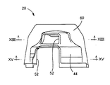
以下、本発明を更に具体的に明らかにするために、本発明の実施形態について説明する。先ず、図1には、本発明の遮熱ゴムカバー付き防振装置に係る一実施形態としての自動車用エンジンマウント10が示されている。このエンジンマウント10は、第一の取付部材としての第一の取付金具12と第二の取付部材としての第二の取付金具14が本体ゴム弾性体16を介して弾性連結されていると共に、第一の取付金具12や本体ゴム弾性体16の周りにストッパ部材としてのストッパ金具18や遮熱ゴムカバーとしてのヒートインシュレータ20が離隔して配設された構造を呈している。この第一の取付金具12がパワーユニット側に取り付けられると共に、第二の取付金具14が車両ボデー側に取り付けられることにより、パワーユニットがボデーに対して防振支持されるようになっている。
Hereinafter, in order to clarify the present invention more specifically, embodiments of the present invention will be described. First, FIG. 1 shows an
なお、図1では、自動車に装着する前のエンジンマウント10の単体での状態が示されているが、本実施形態では、装着状態において、パワーユニットの分担支持荷重がマウント軸方向(図1中、上下)に入力される。従って、マウント装着状態下では、本体ゴム弾性体16の弾性変形に基づき第一の取付金具12と第二の取付金具14が軸方向で互いに接近する方向に変位する。また、かかる装着状態下、防振すべき主たる振動は、略マウント軸方向に入力されることとなる。以下の説明中、特に断りのない限り、上下方向は、マウント軸方向となる図1中の上下方向をいう。
1 shows the state of the
ここで、本実施形態に係るエンジンマウント10は、内部に非圧縮性流体が封入された流体封入式の防振装置とされており、例えば特許文献1(特開2005−172202号公報)等に示されるような公知の構造が採用されることから、その詳細な説明を省略するが、筒状を有する第二の取付金具14の一方(図1中、上)の開口部側に略円板形状乃至は円柱形状の第一の取付金具12が離隔配置されて、それら両金具12,14の間に裁頭円錐台形状の本体ゴム弾性体16が配設されている。第一の取付金具12の外周面が本体ゴム弾性体16の小径側端面に加硫接着されていると共に、第二の取付金具14の内周面が本体ゴム弾性体16の大径側端部外周面に加硫接着されていることによって、第一の取付金具12と第二の取付金具14が弾性連結されていると共に、第二の取付金具14の一方の開口部が本体ゴム弾性体16で流体密に覆蓋されている。また、図面に明示されていないが、第二の取付金具14の他方の開口部に蓋部材が配設されて、かかる開口部が蓋部材で流体密に覆蓋せしめられている。
Here, the
これにより、本体ゴム弾性体16と蓋部材で覆蓋された第二の取付金具14の内側には、壁部の一部が本体ゴム弾性体16で構成されて、本体ゴム弾性体16の弾性変形に基づき圧力変動が生ぜしめられる受圧室が形成されている。なお、特許文献1に示されているように、蓋部材の一部がゴム膜で構成されて、ゴム膜自体の弾性変形により受圧室の圧力変動を調節したり、電磁式アクチュエータ等を用いてゴム膜を強制的に加振変位させて、受圧室の圧力変動を能動的に制御することも可能である。
As a result, a part of the wall portion is constituted by the main rubber
また、本体ゴム弾性体16の外側を覆うようにして、可撓性膜としての弾性変形容易なダイヤフラム22が配設されていることによって、本体ゴム弾性体16を挟んで受圧室と反対側には、ダイヤフラム22の弾性変形に基づき容積変化が容易に許容される平衡室が形成されている。即ち、ダイヤフラム22が、マウント本体の外部に露呈している。これら受圧室と平衡室には、水やアルキレングリコール、ポリアルキレングリコール等の非圧縮性流体が封入されている。また、受圧室と平衡室の間には、それらを相互に連通せしめるオリフィス通路が形成されている。このオリフィス通路を通じて流動せしめられる流体の共振周波数が、防振すべき振動にチューニングされている。
Further, a
特に、第一の取付金具12の上端部分には、取付片24が一体形成されており、取付片24に貫設された挿通孔26に固定用ボルトが挿通されて、パワーユニット側の取付部材に螺着固定されるようになっている。また、第二の取付金具14の他方(図1中、下)の開口部側に、筒状の取付ブラケット28が固定されており、取付ブラケット28が車両ボデー側の取付部材にボルト等で固定されるようになっている。これにより、自動車用エンジンマウント10が、パワーユニットと車両ボデーの間に介装されるようにして自動車に装着されて、パワーユニットを車両ボデーに対して防振支持せしめるようになっている。
In particular, a mounting
かかる装着状態下、第一の取付金具12と第二の取付金具14の間に振動が入力されて、受圧室と平衡室の間に相対的な圧力変動が生ぜしめられて、オリフィス通路を通じての流体の流動量が確保されることとなり、かかる流体の共振作用等の流動作用に基づいて防振効果が発揮されるようになっている。
Under such a mounting state, vibration is input between the first mounting
そこにおいて、第二の取付金具14の一方(図1中、上)の端部には、軸直角方向外方に広がる鍔状部30が一体形成されており、この鍔状部30に対してストッパ金具18が固定されている。
In this case, a hook-shaped
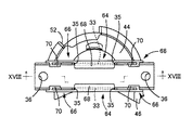
詳細には、ストッパ金具18は、図2〜4にも示されているように、軸直角方向に延びる略矩形平板形状の当接板部32を備えていると共に、当接板部32の両端から下方に向かって延びる略矩形板状の脚部34の一対を備えていて、全体として門形状を呈している。この当接板部32の各端部と脚部34の上端部が一体形成されてなる当接板部32と脚部34の連結部位は、滑らかに湾曲している。
Specifically, as shown in FIGS. 2 to 4, the stopper fitting 18 includes a
また、脚部34の下端部が屈曲して、当接板部32と略平行に延びる矩形平板形状を有していると共に、その下端部に挿通孔36が貫設されている。一対の脚部34,34の対向面間距離が、ダイヤフラム22の外形寸法よりも大きくされている。脚部34の高さ寸法が、マウント本体の第二の取付金具14の鍔状部30から第一の取付金具12に至る高さ寸法に比して十分に大きくされている。
Further, the lower end portion of the
さらに、ストッパ金具18の幅方向(図3中、上下または図4中、左右)の両端部には、支持板部38がそれぞれ一体形成されている。支持板部38は、ストッパ金具18の幅方向端部から上方に延びる平板形状を有しており、幅方向端部の全体に亘って略一定の高さ寸法で延びている。即ち、ストッパ金具18には、幅方向で対向位置せしめられた一対の支持板部38,38と当接板部32および一対の脚部34,34が協働して、ストッパ金具18の外方に向かって開口する略一定の凹状断面で、一対の脚部34,34およびその間の当接板部32を連続して延びる係止凹溝40が形成されている。
Further,
特に、当接板部32の幅方向(図3中、上下)の両端縁部から立ち上がって、当接板部32と略平行に延びる支持板部38の先端面の中央には、切欠状の段差部としての位置決め用溝33が形成されている。位置決め用溝33は支持板部38の先端面を所定の深さ寸法だけ切り欠くように形成されて、位置決め用溝33の底面が当接板部32と略平行に延びており、その長手方向(図2,3中、左右)に延びる両端面が当接板部32における脚部34との連結部分に至らない幅方向縁部の上方に位置せしめられている。このような位置決め用溝33が支持板部38に形成されていることにより、支持板部38の先端面には、位置決め用溝33の長手方向両端面で構成された段差面35,35が形成されている。かかる段差面35は、位置決め用溝33の底面から上方に向かって位置決め用溝33の長手方向外方に傾斜している。
In particular, a notch-like shape is formed at the center of the front end surface of the
このような構造とされたストッパ金具18の一対の脚部34,34の間に、マウント本体の第一の取付金具12およびダイヤフラム22が挟み込まれるようにして、脚部34の下端部が第二の取付金具14の鍔状部30に重ね合わせられると共に、鍔状部30に突設された固定用ボルト42が脚部34の挿通孔36に挿通されて固定用ナットを用いて螺着固定されている。これにより、ストッパ金具18が第一の取付金具12およびダイヤフラム22の外方に離隔位置せしめられて、第一の取付金具12の上方にストッパ金具18の当接板部32が所定距離を隔てて対向位置せしめれた形態で、ストッパ金具18が第二の取付金具14の鍔状部30に固定されている。
The
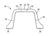
一方、ヒートインシュレータ20は、図5〜15にも示されているように、ゴム弾性材を用いて形成されており、第一膜部44や第二膜部46、中央連結板部48、一対の外側連結板部50,50を含んで構成されて、全体として下方に向かって開口する略逆カップ形状を有している。
On the other hand, as shown in FIGS. 5 to 15, the
第一膜部44は、空洞の略四半球形状を有していると共に、周壁部分の適当な箇所に、複数の窓部52が形成されている。
The
第二膜部46は、第一膜部44に比して幅寸法の小さな袋形状を有していると共に、中央部分に大きな切り欠き状の窓部54が形成されている。また、第二膜部46の周壁部分には、板状を有する放熱板部56が外方に向かって突設されている。
The
これら第一膜部44と第二膜部46が、幅方向(図6,7中、上下)に所定距離を隔てて対向位置せしめられていると共に、それらの対向面間に略矩形平板形状を有する中央連結板部48と一対の外側連結板部50,50が配されて、各連結板部48,50の幅方向端部が第一膜部44の内周縁部分と第二膜部46の内周縁部分に一体形成されていることにより、第一膜部44と第二膜部46が中央および外側連結板部48,50を介して相互に連結された構造を呈している。
The
特に本実施形態では、中央連結板部48が、第一膜部44と第二膜部46の対向方向に直交する方向(図6,7中、左右)の中央部分に位置せしめられていることで、ヒートインシュレータ20の底部中央として構成されている。また、各外側連結板部50が、中央連結板部48から当該直交方向に離隔した外方に位置せしめられていることによって、それぞれヒートインシュレータ20の周壁部分の一部として構成されている。また、中央連結板部48は、その長手寸法がストッパ金具18の当接板部32の長手寸法よりも小さな略矩形平板形状を有していると共に、外側連結板部50は、その長手寸法が中央連結板部48の長手寸法よりも小さな矩形平板形状を有している。
In particular, in the present embodiment, the central connecting
また、中央連結板部48には、下方に向かって突出するストッパゴム58が一体形成されている。この緩衝ゴムとしてのストッパゴム58は、矩形平板形状の板部が軸方向に複数重ね合わせられると共に、突出方向の先端部分に向かって外形寸法が次第に小さくなる形態を有している。また、ストッパゴム58が、ヒートインシュレータ20の底部中央の幅方向一方(図6中、上)の第二膜部46側に偏倚して設けられている。
In addition, a
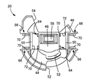
また、ヒートインシュレータ20における第一膜部44および第二膜部46の内周縁部には、全体に亘って略一定の高さ寸法で外方に突出する平板形状の係止板部60が設けられている。これら一対の係止板部60,60が、第一膜部44および第二膜部46の対向方向に所定距離を隔てて対向位置せしめられていることで、ヒートインシュレータ20には、一対の係止板部60,60と一対の係止板部60,60の間に延びる中央連結板部48および一対の外側連結板部50,50が協働して、ヒートインシュレータ20の外方に開口する略一定の凹状断面で中央部分から両側の周縁部分に至る領域を連続して延びる嵌入凹所62が形成されている。このことからも明らかなように、一対の係止板部60,60は、中央連結板部48や一対の外側連結板部50,50によって相互に連結されている。また、嵌入凹所62の幅寸法や長手寸法は、一対の支持板部38,38を備えたストッパ金具18の幅寸法や長手寸法よりも僅かに大きくされている。
Further, the inner peripheral edge portions of the
各係止板部60において、中央連結板部48と連結された部分には、中央爪部64が設けられていると共に、外側連結板部50と連結された部分には、外側爪部66が設けられている。換言すると、一対の中央爪部64,64が、ヒートインシュレータ20の底部中央において、中央連結板部48の幅方向に離隔して対向位置せしめられている。更に、各一対の外側爪部66,66が、ヒートインシュレータ20の各周壁部分において、外側連結板部50の幅方向に離隔して対向位置せしめられていると共に、ヒートインシュレータ20の中心を挟んだ軸直角方向一方向で対向位置せしめられている。
In each locking
中央爪部64や外側爪部66は、何れも、係止板部60の上端部分から幅方向内側に延びる矩形平板形状の横壁部68と横壁部68の内側端縁部から下方又は内方に向かって略矩形平板形状に延びる縦壁部70を含んで構成されている。中央爪部64や外側爪部66の長手寸法が、中央連結板部48や外周連結板部50の長手寸法と略同じ大きさに設定されているため、中央爪部64の長手寸法が、外側爪部66の長手寸法よりも大きくされている。
The
特に本実施形態では、中央爪部64において、横壁部68の厚さ寸法が係止板部60の厚さ寸法と同じかそれよりも僅かに小さくされていると共に、縦壁部70の厚さ寸法が係止板部60の厚さ寸法に比して十分に大きくされていることによって、中央爪部64の縦壁部70の厚さ寸法が、横壁部68の厚さ寸法に比して十分に大きくされている。一方、外側爪部66の横壁部68の厚さ寸法と縦壁部70の厚さ寸法は、ともに係止板部60の厚さ寸法と略同じとされている。
In particular, in the present embodiment, in the
また、中央爪部64の縦壁部70が、係止板部60と横壁部68の幅寸法分だけ幅方向に離隔して対向位置せしめられていると共に、係止板部60と平行に延びている。また、縦壁部70の高さ寸法が、係止板部60の上端部分と同じ高さ位置にある横壁部68の内側端部から各連結板部48,50に向かって延びて、突出先端部分が連結板部48,50と当接しない大きさとされている。特に本実施形態では、縦壁部70の係止板部60と対向位置せしめられる側の内側端部が、軸方向中間部分から突出先端部分に行くに従って幅寸法が小さくなる先細り形状とされている。また、中央爪部64の長手方向(図7,8中、左右)の寸法が、ストッパ金具18の支持板部38に形成された位置決め用溝33の長手方向(図2,3中、左右)の寸法、換言すると一対の段差面35,35の間の離隔距離よりも僅かに小さくされている。
Further, the
さらに、上述の説明からも明らかなように、ヒートインシュレータ20において、中央爪部64が一体形成された中央連結板部48と外側爪部66が一体形成された外側連結板部50とが、連結板部48,50の幅方向に直交する方向(長手方向)に離隔して設けられていることによって、各係止板部60に形成された中央爪部64と各外側爪部66が、該長手方向に所定距離を隔てて対向位置せしめられていると共に、それら中央爪部64と各外側爪部66の間には、中央連結板部48と各外側連結板部50の間に位置せしめられる矩形状の肉抜き孔72が形成されている。
Further, as is apparent from the above description, in the
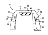
このような構造とされたヒートインシュレータ20が、ストッパ金具18が固定されたマウント本体に対して、門形状のストッパ金具18の内側と第一の取付金具12およびダイヤフラム22の間に差し入れられて、ヒートインシュレータ20の嵌入凹所62に対してストッパ金具18が嵌め込まれている。そして、ヒートインシュレータ20の中央連結板部48にストッパ金具18の当接板部32が重ね合わせられていると共に、ヒートインシュレータ20の各外側連結板部50にストッパ金具18の各脚部34の中間部分が重ね合わせられている。
The
さらに、ヒートインシュレータ20の中央爪部64と外側爪部66の各縦壁部70と係止板部60の間の離隔距離を広げるようにして、爪部64,66を弾性変形させて、縦壁部70が、ストッパ金具18の支持板部38の幅方向外方乃至は軸方向外方から支持板部38を超えて、支持板部38の内側の係止凹溝40に位置せしめられている。更に、ストッパ金具18の当接板部32に突設された支持板部38が、中央爪部64の縦壁部70と係止板部60の間に挟み込まれていると共に、支持板部38の上端部分が横壁部68と対向せしめられている。更にまた、ストッパ金具18の各脚部34に突設された支持板部38が、外側爪部66の縦壁部70と係止板部60の間に挟み込まれていると共に、支持板部38の上端部分が横壁部68と対向せしめられている。なお、各爪部64,66の横壁部68と支持板部38の上端部分が当接しているか離隔しているかは特に限定されるものでない。ヒートインシュレータ20の各連結板部48,50がストッパ金具18に重ね合わせられていると共に、各爪部64,66の縦壁部70と係止板部60の間に支持板部が38挟み込まれていることによって、ヒートインシュレータ20がストッパ金具18に固定的に支持されているのである。
Further, the
ここで、中央爪部64が支持板部38の位置決め用溝33に嵌め込まれて、中央爪部64の横壁部68と位置決め用溝33の底面が対向せしめられて当接または離隔していると共に、中央爪部64の長手方向の両端面がストッパ金具18の各段差面35とそれぞれ対向せしめられている。中央爪部64の長手寸法が一対の段差面35,35の離隔距離よりも僅かに小さくされていることで、中央爪部64の中央部分が一対の段差面35,35の対向面間の中央に位置せしめられると、中央爪部64の端面と段差面35が厳密には離隔されているが、それら端面と段差面35の離隔距離は無視できるほどに小さくされていることによって、中央爪部64の各端面が各段差面35に実質的に当接している。
Here, the
なお、本実施形態に係る自動車用エンジンマウント10では、例示の如き形態に限定されるものでなく、例えば中央爪部64の長手寸法を一対の段差面35,35の離隔距離よりも大きくして、中央爪部64の位置決め用溝33への嵌め込みに際して、中央爪部64を圧縮変形させつつ、中央爪部64の端面を段差面35に当接させることも可能である。
Note that the
これにより、ストッパ金具18の当接板部32に対する中央爪部64の長手方向の変位が制限されており、ヒートインシュレータ20の中央部分が、ストッパ金具18の中央部分の当接板部32に位置決めされて、中央爪部64の支持板部38の挟み込みにより固定的に支持されている。また、ヒートインシュレータ20の中央部分の位置決めに伴い、ヒートインシュレータ20の周壁部分がストッパ金具18の外周側の一対の脚部34,34に位置決めされて、外側爪部66の支持板部38の挟み込みにより固定的に支持せしめられている。その結果、ヒートインシュレータ20が、第一の取付金具12およびダイヤフラム22の外方に所定の距離を隔てて位置せしめられた状態が保持されつつ、それら第一の取付金具12およびダイヤフラム22側から被せられるように配設されて、ストッパ金具18を介してマウント本体に固定されている。
Thereby, the displacement in the longitudinal direction of the
また、かかる固定状態下、ヒートインシュレータ20の中央連結板部48がストッパ金具18の当接板部32に重ね合わせられていることに基づき、中央連結板部48に突設されたストッパゴム58が、当接板部32と第一の取付金具12の軸方向対向面間に位置せしめられて、ストッパ金具18側から第一の取付金具12に向かって突出せしめられている。また、特に本実施形態では、ストッパ金具18における当接板部32と脚部34の連結部分が、ヒートインシュレータ20の肉抜き孔72に位置せしめられている。
Further, under such a fixed state, the
なお、ヒートインシュレータ20のマウント本体への組付けは、マウント本体に固定されたストッパ金具18に対して固定することにより実現されても良いし、またマウント本体に固定される前のストッパ金具18にヒートインシュレータ20を固定して、ストッパ金具18がマウント本体に固定されることによって実現されても良い。
The assembly of the
このような構造とされたヒートインシュレータ20付きの自動車用エンジンマウント10においては、第一の取付金具12と第二の取付金具14の間にリバウンド方向の大荷重が入力されて、両金具12,14の一方が他方に対して大きく離隔変位することとなっても、ストッパ金具18の当接板部32と第一の取付金具12が、ヒートインシュレータ20に一体形成されたストッパゴム58を介して打ち当たることによって、両金具12,14のリバウンド方向の変位が緩衝的に制限される。その結果、本体ゴム弾性体16の過大な変形が抑えられて、耐久性が向上され得る。なお、上述の説明からも明らかなように、本実施形態に係る第一の取付金具12と第二の取付金具14のリバウンドストッパ機構が、ストッパ金具18やストッパゴム58を含んで構成されている。
In the
また、このような自動車用エンジンマウント10は、内燃機関の輻射熱等が晒されやすい場所に配されることとなるが、第一の取付金具12およびダイヤフラム22の外面を離隔して覆うようにヒートインシュレータ20が配されていることから、マウント本体の内部に設けられる本体ゴム弾性体16は勿論、ダイヤフラム22もヒートインシュレータ20で好適に保護されることとなり、ダイヤフラム22や本体ゴム弾性体16の耐久性が有利に向上され得る。
In addition, such an
そこにおいて、ヒートインシュレータ20が、中央爪部64と外側爪部66を利用して、所定の面積を備え且つ剛体のストッパ金具18に支持されていることにより、ヒートインシュレータ20のマウント本体への支持状態が安定する。その結果、ヒートインシュレータ20がダイヤフラム22等に過度に当接することが抑えられて、当接による不具合が有利に解消され得る。
In this case, the
特に、ヒートインシュレータ20のストッパ金具18、延いてはマウント本体に対する位置決めが、中央爪部64の端面が支持板部38の段差面35に当接することで実現されることから、位置決め構造が簡単となる。しかも、自動車への装着状態下、中央爪部64の端面と支持板部38の段差面35の当接状態が保持されていることによって、ヒートインシュレータ20のマウント本体に対する位置ずれが好適に抑えられる。
In particular, since the positioning of the
また、ヒートインシュレータ20と一体形成された中央爪部64や外側爪部66を用いてストッパ金具18に固定されていることにより、ボルト等を用いて固定する場合に比して、固定構造が簡単となるのであり、それによって、前述の位置決め構造を含む全体構造の複雑化が有利に解消され得る。
In addition, since the
さらに、ヒートインシュレータ20の中央部分と外周部分の両方がストッパ金具18に支持されるようになっていることから、組み付け作業が容易になることに加えて、例えばヒートインシュレータ20の中央部分が第一の取付金具12側に支持されると共に、ヒートインシュレータ20の外周部分が第二の取付金具14側に支持されることに起因して、第一の取付金具12と第二の取付金具14の相対変位による応力集中がヒートインシュレータ20に生じることが回避されることとなり、ヒートインシュレータ20の耐久性が向上され得る。
Further, since both the central portion and the outer peripheral portion of the
更にまた、ストッパ金具18とヒートインシュレータ20が互いに別体形成されていることにより、ヒートインシュレータ20の形状や大きさ等をストッパ金具18の形態で大きく制限されることなく、設計変更することが出来、それによって、ヒートインシュレータ20ならびにストッパ金具18の設計自由度が十分に確保され得る。
Furthermore, since the stopper fitting 18 and the
それ故、製造効率の向上や低コスト化が有利に達成され得ることに加え、ヒートインシュレータ20における設計変更や、マウント本体との離隔保持が高度に実現されることにより、所期の遮熱効果が安定して得られるのである。
Therefore, in addition to being able to advantageously achieve improvement in manufacturing efficiency and cost reduction, the design change in the
特に本実施形態では、ストッパゴム58がヒートインシュレータ20と一体形成されていることにより、部品点数の増大が抑えられて、組み付け作業が一層容易になる。
In particular, in this embodiment, the
また、本実施形態では、ヒートインシュレータ20の係止板部60やストッパ金具18の支持板部38が、ぞれぞれ一方の周縁部(端部)から中央部分を経て他方の周縁部(端部)にまで連続して延びて、それら支持板部38と係止板部60が全体に亘って幅方向で重ね合わせられている。これにより、ヒートインシュレータ20のストッパ金具18に対する支持状態が一層安定する。
Further, in the present embodiment, the locking
以上、本発明の一実施形態について詳述してきたが、これはあくまでも例示であり、かかる実施形態における具体的な記載によって、本発明は、何等限定されるものでなく、当業者の知識に基づいて種々なる変更、修正、改良等を加えた態様で実施可能であり、また、そのような実施態様が、本発明の趣旨を逸脱しない限り、何れも、本発明の範囲内に含まれるものであることは、言うまでもない。 As mentioned above, although one embodiment of the present invention has been described in detail, this is merely an example, and the present invention is not limited to any specific description by this embodiment, and is based on the knowledge of those skilled in the art. The present invention can be implemented with various changes, modifications, improvements, etc., and all such embodiments are within the scope of the present invention without departing from the spirit of the present invention. Needless to say, there is.
例えば、ストッパ金具18やヒートインシュレータ20、マウント本体等における形状や大きさ、構造、数、配置等の形態は、例示の如きものに限定されない。以下の説明において前記実施形態と実質的に同一の構造とされた部材および部位については、図中に同一の符号を付することにより、それらの詳細な説明を省略する。
For example, forms such as the shape, size, structure, number, and arrangement of the stopper fitting 18, the
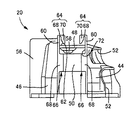
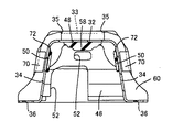
すなわち、前記実施形態では、ヒートインシュレータ20が一対の袋状の第一膜部44および第二膜部46を含んで構成されていたが、要求される遮熱効果や製作性等に応じて、例えば図16〜18にも示されているように、第二膜部46がストッパ金具18の係止板部60に沿って重ね合わせられる板形状とされていても良い。
That is, in the said embodiment, although the
また、前記実施形態では、ヒートインシュレータ20の周壁部分が、ストッパ金具18の両脚部34,34に対して、それぞれ一対の外側爪部66,66を介して固定されるようになっていたが、一方の脚部34のみに対して外側爪部66を利用して固定することも可能である。
Moreover, in the said embodiment, although the surrounding wall part of the
また、ストッパゴム58がヒートインシュレータ20と一体形成される必要は必ずしもなく、例えばストッパゴム58を設けずに、第一の取付金具とストッパ金具の当接板部をヒートインシュレータの中央連結板部を介して打ち当たらせることも可能であり、或いはストッパ金具の当接板部の底面にストッパゴムを突設すると共に、ストッパゴムをヒートインシュレータの中央連結板部に重ね合わせたり、中央連結板部に貫設した孔にストッパゴムを挿通することも可能である。
The
また、前記実施形態では、支持板部38の段差面35が、支持板部38の先端部分において切り欠き状に設けられた位置決め用溝33の長手方向の端面によって構成されていたが、例えば支持板部の先端部分に突設された突部の端面で構成しても良い。
In the above embodiment, the stepped
また、段差面35を各支持板部38にそれぞれ一対設ける必要は必ずしもなく、各支持板部38における一対の段差面35,35をそれぞれ一つにして、それら段差面を当接板部の中央を挟んで互いに異なる方向に配して、一方の中央爪部の長手方向一方の端面に一方の段差面を当接させると共に、他方の中央爪部の長手方向他方の端面に他方の段差面を当接させることによって、一方の支持板部の段差面と他方の支持板部の段差面が協働してヒートインシュレータの中央部分の変位を制限して、ストッパ金具の当接板部に位置決めすることも可能である。
Further, it is not always necessary to provide a pair of stepped
さらに、前記実施形態では、内部に受圧室や平衡室、オリフィス通路を形成して、内部に非圧縮性流体が封入されたリキッド式のエンジンマウント10に対して本発明が適用されていたが、これに限定されるものでなく、例えば第一の取付金具と第二の取付金具が本体ゴム弾性体で連結されただけのソリッド式の防振装置に対して適用することも勿論可能である。
Furthermore, in the above embodiment, the present invention is applied to the liquid
加えて、前記実施形態では、自動車用エンジンマウントに本発明を適用したものの一具体例について例示されていたが、その他ストッパ機構およびヒートインシュレータの配設が要求される各種の防振装置に対して適用可能であることは無論である。 In addition, in the said embodiment, although the specific example of what applied this invention to the engine mount for motor vehicles was illustrated, it is with respect to the various vibration isolators with which arrangement | positioning of a stopper mechanism and a heat insulator is requested | required. Of course, it is applicable.
10:自動車用エンジンマウント、12:第一の取付金具、14:第二の取付金具、16:本体ゴム弾性体、18:ストッパ金具、20:ヒートインシュレータ、32:当接板部、34:脚部、35:段差面、40:係止凹溝、58:ストッパゴム、64:中央爪部、66:外側爪部 10: Engine mount for automobile, 12: First mounting bracket, 14: Second mounting bracket, 16: Rubber elastic body of main body, 18: Stopper bracket, 20: Heat insulator, 32: Contact plate portion, 34: Leg Part, 35: step surface, 40: locking groove, 58: stopper rubber, 64: central claw part, 66: outer claw part
Claims (7)
前記ストッパ部材における前記当接板部と前記一対の脚部に、それぞれ外方に開口する係止凹溝を形成すると共に、該当接板部の該係止凹溝の両側壁部には高さ方向先端部分に切欠状の段差部を設ける一方、前記遮熱ゴムカバーの中央部分の外面に中央爪部を一体形成すると共に該遮熱ゴムカバーの周壁部分の外面に外側爪部を一体形成して、該当接板部における該係止凹溝の両側壁部に該中央爪部を係止すると共に、該一対の脚部における該係止凹溝の両側壁部に該外側爪部を係止し、更に、該当接板部における該係止凹溝の両側壁部に設けた該段差部の両端段差面に対して該中央爪部の両端面を当接させることにより該遮熱ゴムカバーの中央部分を該ストッパ部材の該当接板部に対して該係止凹溝の長手方向で位置決めして、該遮熱ゴムカバーを該ストッパ部材に固定したことを特徴とする遮熱ゴムカバー付き防振装置。 A first mounting member attached to one member to be anti-vibration connected and a second attachment member attached to the other member to be anti-vibration connected to each other by a main rubber elastic body, while abutting extending in a direction perpendicular to the axis Using a portal-shaped stopper member having a pair of leg portions at both ends of the plate portion, the lower ends of the pair of leg portions are fixed to the second mounting member and project outward from the first mounting member. By assembling the stopper member, the corresponding contact plate portion and the first mounting member are opposed to each other, and the corresponding mounting plate portion and the first mounting member are brought into contact with each other, thereby the first mounting member. A rebound stopper mechanism that limits the amount of displacement of the second mounting member and the second mounting member in a direction away from each other, and a heat insulating rubber cover that covers the outer surface of the main rubber elastic body is separated from the first mounting member side To cover the rubber elastic body A vibration damping device with heat insulating rubber cover that,
Each of the contact plate portion and the pair of leg portions of the stopper member is formed with a locking groove that opens outward, and heights are formed on both side walls of the locking groove of the contact plate portion. A notch-shaped step portion is provided at the front end portion in the direction, while a central claw portion is integrally formed on the outer surface of the central portion of the heat insulating rubber cover and an outer claw portion is integrally formed on the outer surface of the peripheral wall portion of the heat insulating rubber cover. The central claw portion is locked to both side wall portions of the locking groove in the corresponding contact plate portion, and the outer claw portion is locked to both side wall portions of the locking groove in the pair of leg portions. Further, the both ends of the central claw portion are brought into contact with the stepped surfaces of both ends of the stepped portion provided on both side walls of the locking groove in the corresponding contact plate portion. Positioning the center part in the longitudinal direction of the locking groove with respect to the corresponding contact plate portion of the stopper member, Bar a thermal barrier rubber covered vibration damping device, characterized in that fixed to the stopper member.
Priority Applications (2)
| Application Number | Priority Date | Filing Date | Title |
|---|---|---|---|
| JP2007184971A JP4772001B2 (en) | 2007-07-13 | 2007-07-13 | Vibration isolator with thermal barrier rubber cover |
| US12/216,880 US8083216B2 (en) | 2007-07-13 | 2008-07-11 | Vibration damping device equipped with rubber heat-insulating cover |
Applications Claiming Priority (1)
| Application Number | Priority Date | Filing Date | Title |
|---|---|---|---|
| JP2007184971A JP4772001B2 (en) | 2007-07-13 | 2007-07-13 | Vibration isolator with thermal barrier rubber cover |
Publications (2)
| Publication Number | Publication Date |
|---|---|
| JP2009019752A JP2009019752A (en) | 2009-01-29 |
| JP4772001B2 true JP4772001B2 (en) | 2011-09-14 |
Family
ID=40294571
Family Applications (1)
| Application Number | Title | Priority Date | Filing Date |
|---|---|---|---|
| JP2007184971A Expired - Fee Related JP4772001B2 (en) | 2007-07-13 | 2007-07-13 | Vibration isolator with thermal barrier rubber cover |
Country Status (2)
| Country | Link |
|---|---|
| US (1) | US8083216B2 (en) |
| JP (1) | JP4772001B2 (en) |
Families Citing this family (11)
| Publication number | Priority date | Publication date | Assignee | Title |
|---|---|---|---|---|
| BRPI0621437A2 (en) | 2006-03-21 | 2012-07-10 | Tmms Co Ltd | electricity conveying devices through vacuum and dielectric materials |
| JP4759539B2 (en) * | 2007-07-13 | 2011-08-31 | 東海ゴム工業株式会社 | Vibration isolator with thermal barrier rubber cover |
| FR2930614B1 (en) * | 2008-04-29 | 2010-05-14 | Hutchinson | ANTI-VIBRATION DEVICE, ANTI-VIBRATION SYSTEM COMPRISING SUCH DEVICE AND METHOD OF MANUFACTURE |
| GB2480494B (en) * | 2010-05-21 | 2017-03-15 | Gm Global Tech Operations Llc | Heat protection for load bearing component |
| GB2514837B (en) * | 2013-06-07 | 2019-04-17 | Bentley Motors Ltd | A heat shield arrangement |
| JP6456341B2 (en) * | 2016-11-17 | 2019-01-23 | 東洋ゴム工業株式会社 | Vibration isolator |
| JP6456340B2 (en) | 2016-11-17 | 2019-01-23 | 東洋ゴム工業株式会社 | Vibration isolator |
| JP6456339B2 (en) | 2016-11-17 | 2019-01-23 | 東洋ゴム工業株式会社 | Vibration isolator |
| US10295010B2 (en) * | 2017-10-18 | 2019-05-21 | Hyundai Motor Company | Fluid-filled engine mounting apparatus |
| CN111341192A (en) * | 2020-03-03 | 2020-06-26 | 浙江工贸职业技术学院 | Real device of instructing of welding machines hand teaching |
| CN112277617A (en) * | 2020-10-29 | 2021-01-29 | 东风汽车股份有限公司 | Power assembly suspension structure for light commercial vehicle and assembling method thereof |
Family Cites Families (17)
| Publication number | Priority date | Publication date | Assignee | Title |
|---|---|---|---|---|
| US2162714A (en) * | 1937-10-08 | 1939-06-20 | Clyde M Hamblin | Vibration dampening fitting |
| JPH0571491A (en) | 1991-06-14 | 1993-03-23 | Mitsui Constr Co Ltd | Pump for pit |
| JP3675872B2 (en) * | 1995-02-27 | 2005-07-27 | 倉敷化工株式会社 | Anti-vibration bushing parts |
| JPH08296681A (en) * | 1995-04-25 | 1996-11-12 | Bridgestone Corp | Antivibration device |
| JP2000057664A (en) | 1998-08-06 | 2000-02-25 | Alpine Electronics Inc | Disk device |
| JP3581924B2 (en) * | 2001-03-09 | 2004-10-27 | 東洋ゴム工業株式会社 | Anti-vibration device |
| JP3767403B2 (en) * | 2001-03-30 | 2006-04-19 | 東海ゴム工業株式会社 | Fluid filled vibration isolator |
| FR2825128B1 (en) * | 2001-05-25 | 2003-08-15 | Hutchinson | ANTI-VIBRATION SUPPORT AND METHOD OF MANUFACTURING SUCH A SUPPORT |
| JP2003056636A (en) | 2001-08-22 | 2003-02-26 | Toyo Tire & Rubber Co Ltd | Anti-vibration device |
| FR2851312B1 (en) * | 2003-02-13 | 2006-06-23 | Hutchinson | HYDRAULIC ANTIVIBRATORY SUPPORT |
| JP2004276764A (en) | 2003-03-17 | 2004-10-07 | Honda Motor Co Ltd | Engine suspension for vehicles |
| JP4401756B2 (en) | 2003-12-15 | 2010-01-20 | 山下ゴム株式会社 | Vibration isolator and its manufacturing method |
| US7055811B2 (en) * | 2004-05-03 | 2006-06-06 | Toyo Tire And Rubber Co., Ltd. | Vibration isolating device |
| JP4135719B2 (en) * | 2004-08-31 | 2008-08-20 | 東海ゴム工業株式会社 | Engine mount |
| FR2880581B1 (en) * | 2005-01-12 | 2007-04-13 | Hutchinson Sa | METHOD FOR MANUFACTURING AN ANTI-VIBRATION DEVICE AND ANTI-VIBRATION DEVICE THAT CAN BE OBTAINED BY THIS METHOD |
| US7581720B2 (en) * | 2005-07-11 | 2009-09-01 | Honda Motor Co., Ltd. | Vibration isolation system and method for engine, and control system and method for active vibration isolation support system |
| JP4759539B2 (en) * | 2007-07-13 | 2011-08-31 | 東海ゴム工業株式会社 | Vibration isolator with thermal barrier rubber cover |
-
2007
- 2007-07-13 JP JP2007184971A patent/JP4772001B2/en not_active Expired - Fee Related
-
2008
- 2008-07-11 US US12/216,880 patent/US8083216B2/en not_active Expired - Fee Related
Also Published As
| Publication number | Publication date |
|---|---|
| US20090026675A1 (en) | 2009-01-29 |
| US8083216B2 (en) | 2011-12-27 |
| JP2009019752A (en) | 2009-01-29 |
Similar Documents
| Publication | Publication Date | Title |
|---|---|---|
| JP4772001B2 (en) | Vibration isolator with thermal barrier rubber cover | |
| JP4759539B2 (en) | Vibration isolator with thermal barrier rubber cover | |
| JP5209339B2 (en) | Engine mount with bracket | |
| JP7000243B2 (en) | Anti-vibration device | |
| JP5535958B2 (en) | Liquid-filled vibration isolator | |
| CN102168737B (en) | Fluid-filled type vibration damping device | |
| JP4802164B2 (en) | Vibration isolator | |
| WO2015145672A1 (en) | Anti-vibration device | |
| CN107250600B (en) | Vibration isolator and damper | |
| JP6595371B2 (en) | Vibration isolator | |
| JP5829156B2 (en) | Vibration isolator | |
| JP2012002328A (en) | Vibration control device | |
| JP5829135B2 (en) | Fluid filled vibration isolator | |
| CN107683378B (en) | Liquid seal vibration-proof device | |
| JP4379920B2 (en) | Fluid filled vibration isolator | |
| JP2013181639A (en) | Vibration-proofing device | |
| JPH0438117Y2 (en) | ||
| JP6329870B2 (en) | Vibration isolator | |
| CN113728177B (en) | Vibration isolator | |
| JP5986515B2 (en) | Fluid filled vibration isolator | |
| JP3978781B2 (en) | Fluid filled vibration isolator | |
| JP2007032745A (en) | Fluid filled vibration isolator | |
| CN107289064B (en) | Square fluid-sealed vibration-damping device | |
| JP4103804B2 (en) | Liquid filled vibration isolator | |
| JP2008196574A (en) | Liquid filled vibration isolator |
Legal Events
| Date | Code | Title | Description |
|---|---|---|---|
| A621 | Written request for application examination |
Free format text: JAPANESE INTERMEDIATE CODE: A621 Effective date: 20100526 |
|
| TRDD | Decision of grant or rejection written | ||
| A01 | Written decision to grant a patent or to grant a registration (utility model) |
Free format text: JAPANESE INTERMEDIATE CODE: A01 Effective date: 20110606 |
|
| A01 | Written decision to grant a patent or to grant a registration (utility model) |
Free format text: JAPANESE INTERMEDIATE CODE: A01 |
|
| A977 | Report on retrieval |
Free format text: JAPANESE INTERMEDIATE CODE: A971007 Effective date: 20110609 |
|
| A61 | First payment of annual fees (during grant procedure) |
Free format text: JAPANESE INTERMEDIATE CODE: A61 Effective date: 20110621 |
|
| FPAY | Renewal fee payment (event date is renewal date of database) |
Free format text: PAYMENT UNTIL: 20140701 Year of fee payment: 3 |
|
| R150 | Certificate of patent or registration of utility model |
Ref document number: 4772001 Country of ref document: JP Free format text: JAPANESE INTERMEDIATE CODE: R150 Free format text: JAPANESE INTERMEDIATE CODE: R150 |
|
| S533 | Written request for registration of change of name |
Free format text: JAPANESE INTERMEDIATE CODE: R313533 |
|
| R350 | Written notification of registration of transfer |
Free format text: JAPANESE INTERMEDIATE CODE: R350 |
|
| LAPS | Cancellation because of no payment of annual fees |