JP4765643B2 - Method for producing molten metal-plated steel strip and gas wiping nozzle - Google Patents
Method for producing molten metal-plated steel strip and gas wiping nozzle Download PDFInfo
- Publication number
- JP4765643B2 JP4765643B2 JP2006020363A JP2006020363A JP4765643B2 JP 4765643 B2 JP4765643 B2 JP 4765643B2 JP 2006020363 A JP2006020363 A JP 2006020363A JP 2006020363 A JP2006020363 A JP 2006020363A JP 4765643 B2 JP4765643 B2 JP 4765643B2
- Authority
- JP
- Japan
- Prior art keywords
- slit
- nozzle
- steel strip
- width
- main
- Prior art date
- Legal status (The legal status is an assumption and is not a legal conclusion. Google has not performed a legal analysis and makes no representation as to the accuracy of the status listed.)
- Expired - Fee Related
Links
- 229910000831 Steel Inorganic materials 0.000 title claims description 68
- 239000010959 steel Substances 0.000 title claims description 68
- 238000004519 manufacturing process Methods 0.000 title claims description 17
- 239000002184 metal Substances 0.000 claims description 32
- 238000007747 plating Methods 0.000 claims description 12
- 238000000034 method Methods 0.000 description 13
- 230000000694 effects Effects 0.000 description 8
- 229910001335 Galvanized steel Inorganic materials 0.000 description 4
- 238000007664 blowing Methods 0.000 description 4
- 230000000052 comparative effect Effects 0.000 description 4
- 230000007423 decrease Effects 0.000 description 4
- 238000009792 diffusion process Methods 0.000 description 4
- 239000008397 galvanized steel Substances 0.000 description 4
- 239000011248 coating agent Substances 0.000 description 2
- 238000000576 coating method Methods 0.000 description 2
- 230000001276 controlling effect Effects 0.000 description 2
- 238000007598 dipping method Methods 0.000 description 2
- 238000009826 distribution Methods 0.000 description 2
- 230000001154 acute effect Effects 0.000 description 1
- 238000010924 continuous production Methods 0.000 description 1
- 238000002347 injection Methods 0.000 description 1
- 239000007924 injection Substances 0.000 description 1
- 238000011835 investigation Methods 0.000 description 1
- 239000007769 metal material Substances 0.000 description 1
- 238000005192 partition Methods 0.000 description 1
- 230000001105 regulatory effect Effects 0.000 description 1
- 229920006395 saturated elastomer Polymers 0.000 description 1
- 238000005507 spraying Methods 0.000 description 1
Images


Description
本発明は、溶融金属めっき浴から連続的に引き上げられる鋼帯の表面に、ガスワイピングノズルからガスを吹き付けて付着金属の厚さを制御する溶融金属めっき鋼帯の製造方法及びこの鋼帯の製造に使用するガスワイピングノズルに関するものである。 The present invention relates to a method of manufacturing a molten metal-plated steel strip in which gas is sprayed from a gas wiping nozzle onto the surface of a steel strip that is continuously pulled up from a molten metal plating bath, and the thickness of the deposited metal is controlled. The present invention relates to a gas wiping nozzle used in the above.
連続溶融めっきプロセスにおいては、一般的に溶融金属が満たされているめっき浴に鋼帯を浸漬させた後、該鋼帯を垂直上方に引き上げる工程の後に、鋼帯表面に付着した溶融金属が板幅方向および板長手方向に均一で所定の付着量になるように、鋼帯と平行な面内に、この鋼帯を挟んで対向して設けた鋼帯幅方向に延在するガスワイピングノズルから気体を鋼帯上に噴出させて、余剰な溶融金属を掻き取り、溶融金属の付着量を制御するガスワイピング方式が行われている。ガスワイピングノズルは、多様な鋼帯幅に対応すると同時に鋼帯引き上げ時の幅方向の位置ズレなどに対応するため、通常、鋼帯の幅より長く、鋼帯の幅端部より外側まで延びている。このようなガスワイピング方式では、鋼帯に衝突した噴流の乱れによって鋼帯下方に落下する溶融金属が周囲に飛び散る、いわゆるスプラッシュが発生したりして、鋼帯表面品質の低下を招く。 In a continuous hot dipping process, the steel strip is generally immersed in a plating bath filled with molten metal, and after the step of pulling the steel strip vertically upward, the molten metal adhering to the surface of the steel strip is removed. From a gas wiping nozzle extending in the width direction of the steel strip provided opposite to the steel strip in a plane parallel to the steel strip so as to have a predetermined adhesion amount in the width direction and the plate longitudinal direction. A gas wiping method in which gas is ejected onto a steel strip to scrape excess molten metal and control the amount of molten metal deposited is performed. The gas wiping nozzle is usually longer than the width of the steel strip and extends to the outside of the width end of the steel strip in order to cope with various steel strip widths and at the same time the positional deviation in the width direction when the steel strip is pulled up. Yes. In such a gas wiping method, the molten metal falling below the steel strip is scattered around due to the turbulence of the jet colliding with the steel strip, so-called splash is generated, and the steel strip surface quality is deteriorated.
連続プロセスにおいて、生産量を増加させるには、鋼帯通板速度(ライン速度)を増加させればよい。しかし、連続溶融めっきプロセスにおいてガスワイピング方式でめっき付着量を制御する場合、溶融金属の粘性により、ライン速度の増加に伴って鋼帯のめっき浴通過直後の初期付着量が増加するため、めっき付着量を一定範囲内に制御するには、ワイピングガス圧力をより高圧に設定せざるを得ず、それによってスプラッシュが大幅に増加し、良好な表面品質を維持できなくなる。 In order to increase the production amount in the continuous process, the steel strip passing speed (line speed) may be increased. However, when controlling the coating amount by gas wiping method in the continuous hot dipping process, the initial adhesion amount immediately after passing through the plating bath of the steel strip increases as the line speed increases due to the viscosity of the molten metal. In order to control the amount within a certain range, the wiping gas pressure has to be set to a higher pressure, thereby greatly increasing the splash and maintaining good surface quality.
上記の問題を解決するため、主として鋼帯に付着した溶融金属の付着量を制御するワイピングノズル(主ノズル)の上下に補助的なノズル(副ノズル)を配置し、副ノズルの作用によって、主ノズルの性能を向上させる方法が以下の通り開示されている。 In order to solve the above problems, auxiliary nozzles (sub nozzles) are arranged above and below a wiping nozzle (main nozzle) that mainly controls the amount of molten metal adhering to the steel strip. A method for improving the performance of the nozzle is disclosed as follows.
特許文献1に開示された方法は、ワイピングノズルから噴射するワイピングガス(主噴流)を遮断するための遮断ガスとして火炎を放射して、主噴流の周りを高温ガスで囲むことで主噴流の流動抵抗を低下させることが可能となり、その結果、主噴流のポテンシャル・コア延長が可能となり、鋼帯への衝突力が向上するとしている。 The method disclosed in Patent Document 1 radiates a flame as a shut-off gas for shutting off a wiping gas (main jet) injected from a wiping nozzle, and surrounds the main jet with a high-temperature gas to flow the main jet. The resistance can be reduced, and as a result, the potential core of the main jet can be extended and the impact force on the steel strip is improved.
特許文献2に開示された方法は、主ノズルと副ノズル間の仕切り板の噴出口先端を鋭角にし、且つ主ノズルから噴射される主噴流に対して副ノズルから噴射される副噴流を5〜20°傾け、ポテンシャル・コアを長くすることで、付着量制御性が向上し、また噴流が安定するため騒音も低減するとしている。
In the method disclosed in
特許文献3に開示された方法は、主ノズルの上下部に、幅方向に3つ以上に分割されて、各分割部がそれぞれ独立に圧力制御可能な補助ノズル(副ノズル)を設けてガスを噴射することより、主ノズルからの主噴流の広がりを抑えられ、ノズル位置での金属帯の湾曲の程度にかかわらず、金属帯幅方向でのめっき付着量の均一性を向上できるとしている。
ところが、特許文献1、2に開示された方法は、いずれも、鋼帯エッジ部で付着量が増大するエッジオーバーコートが避けられない。これは、鋼帯エッジ部では、鋼帯センター部に比較した場合、吹きつけた気体は鋼帯横方向に逃げる割合が高いため、衝突圧力は相対的に低下、その結果、払拭力が低下することが避けられないからである。特許文献3に開示された方法では、分割したエッジ部の圧力を上昇させれば、エッジオーバーコートは抑制可能となるが、分割した各部の圧力を制御する必要があり、機構が複雑化するため、実機化にはあまり適さない。
However, the methods disclosed in
本発明は上記の問題点を解決し、溶融金属の付着量制御におけるエッジオーバーコートの発生を防止できる溶融金属めっき鋼帯の製造方法及びこの鋼帯の製造に使用するガスワイピングノズルを提供することを課題とする。 The present invention solves the above-described problems and provides a method for producing a molten metal-plated steel strip capable of preventing the occurrence of edge overcoat in the control of the amount of molten metal applied, and a gas wiping nozzle used for the production of this steel strip. Is an issue.
上記課題を解決する本発明の手段は下記の通りである。
(1)溶融金属めっき浴から連続的に引き上げられる鋼帯の表面に、ガスを噴射する複数のスリットを有するガスワイピングノズルからガスを吹き付けて付着金属の厚さを制御する溶融金属めっき鋼帯の製造方法において、前記複数のスリットのなかで負荷圧力が最大のスリットのスリット幅をノズル幅方向外側に向かって大きくすることを特徴とする溶融金属めっき鋼帯の製造方法。
Means of the present invention for solving the above problems are as follows.
(1) A molten metal plated steel strip that controls the thickness of the adhered metal by blowing gas from a gas wiping nozzle having a plurality of slits for injecting gas onto the surface of the steel strip that is continuously pulled up from the molten metal plating bath. In the manufacturing method, the slit width of the slit having the maximum load pressure among the plurality of slits is increased toward the outside in the nozzle width direction, and the manufacturing method of the molten metal plated steel strip is characterized.
(2) (1)に記載の溶融金属めっき鋼帯の製造方法において、前記複数のスリットのなかで負荷圧力が最大のスリット以外のスリットのスリット幅を0.2mm以上とすることを特徴とする溶融金属めっき鋼帯の製造方法。 (2) In the method for manufacturing a molten metal plated steel strip according to (1), a slit width of a slit other than a slit having a maximum load pressure among the plurality of slits is 0.2 mm or more. A method for producing a molten metal-plated steel strip.
(3)溶融金属めっき浴から連続的に引き上げられる鋼帯の表面に、ガスを噴射する複数のスリットを有するガスワイピングノズルからガスを吹き付けて付着金属の厚さを制御する溶融金属めっき鋼帯用ワイピングノズルにおいて、前記複数のスリットのなかで負荷圧力が最大のスリットのスリット幅をノズル幅方向外側に向かって大きくすることを特徴とするワイピングノズル。 (3) For a molten metal plated steel strip that controls the thickness of the deposited metal by blowing gas from a gas wiping nozzle having a plurality of slits for injecting gas onto the surface of the steel strip that is continuously pulled up from the molten metal plating bath In the wiping nozzle, the slit width of the slit having the maximum load pressure among the plurality of slits is increased outward in the nozzle width direction.
(4) (3)に記載のワイピングノズルにおいて、前記複数のスリットのなかで負荷圧力が最大のスリット以外のスリットのスリット幅を0.2mm以上とすることを特徴とするワイピングノズル。 (4) The wiping nozzle according to (3), wherein a slit width of a slit other than the slit having the maximum load pressure among the plurality of slits is 0.2 mm or more.
本発明によれば、ガスワイピングノズルのワイピング力に大きな影響を与える主スリット(複数のスリットのなかで負荷圧力が最大のスリット)から噴射される主噴流の拡散が副スリット(主スリット以外のスリット)からの副噴流によって防止され、主噴流のポテンシャル・コア延長による鋼帯面衝突圧力向上によってワイピング力を向上でき、また、主スリットのスリット幅をノズル幅方向外側に向かって大きくすることで、鋼帯中央部に対して鋼帯端部のワイピング力が強化できる。その結果、エッジオーバを防止して鋼帯幅方向の付着量均一化が達成でき、また溶融金属材料コスト低減にも寄与する。また、従来のシングルスリットからなるガスワイピングノズルに比べて、主噴流の圧力を低下できることから、スプラッシュの発生も抑制できる。 According to the present invention, the diffusion of the main jet injected from the main slit (the slit having the maximum load pressure among the plurality of slits) that greatly affects the wiping force of the gas wiping nozzle is the sub slit (the slits other than the main slit). ), The wiping force can be improved by improving the steel sheet surface collision pressure by extending the potential core of the main jet, and by increasing the slit width of the main slit toward the outside in the nozzle width direction, The wiping force at the end of the steel strip can be strengthened relative to the center of the steel strip. As a result, it is possible to prevent edge over and achieve uniform adhesion amount in the width direction of the steel strip, and contribute to reducing the cost of the molten metal material. Moreover, since the pressure of the main jet can be reduced as compared with a conventional gas wiping nozzle composed of a single slit, the occurrence of splash can be suppressed.
本発明が対象とするガスワイピングノズルは、溶融金属めっき浴から連続的に引き上げられる鋼帯の表面にガスを吹き付けて付着金属の厚さを制御するためのガスワイピングノズルであって、該ガスワイピングノズルは、ガスを噴射する複数のスリットを、鋼帯走行方向に有するものである。 A gas wiping nozzle to which the present invention is directed is a gas wiping nozzle for controlling the thickness of a deposited metal by blowing gas onto the surface of a steel strip that is continuously pulled up from a molten metal plating bath. The nozzle has a plurality of slits for injecting gas in the running direction of the steel strip.
本発明では、この複数のスリットのなかで、負荷圧力が最大のもの、すなわちガス圧力が最も高いスリットを主スリットと記載し、前記主スリット以外のスリットを副スリットと記載する。また、主スリットから噴射されるガスの噴流を主噴流、副スリットから噴射されるガスの噴流を副噴流と記載する。 In the present invention, among the plurality of slits, the slit having the highest load pressure, that is, the highest gas pressure is referred to as a main slit, and slits other than the main slit are referred to as sub-slits. Further, a jet of gas injected from the main slit is referred to as a main jet, and a jet of gas injected from the sub slit is referred to as a sub jet.
主スリットのスリット幅はワイピング力に与える影響が大きく、該スリット幅が大きいほどワイピング力は増大する。一方、ワイピング力は、副スリットのスリット幅にはあまり依存しない。しかし、副スリットからの副噴流を適切に制御すると、主ノズルからの主噴流の拡散を防止でき、主噴流のポテンシャル・コア延長による鋼帯面衝突圧力向上によってワイピング力を向上させることができる。したがって、本発明が対象とする複数のスリット(ガス噴射口)を有するガスワイピングノズルを用いると、通常のシングルスリットノズルに比較して付着量を薄くできる。以下、この点を説明する。 The slit width of the main slit has a large influence on the wiping force, and the wiping force increases as the slit width increases. On the other hand, the wiping force does not depend much on the slit width of the sub slit. However, if the sub jet flow from the sub slit is appropriately controlled, the main jet flow from the main nozzle can be prevented from diffusing, and the wiping force can be improved by improving the steel plate surface collision pressure by extending the potential core of the main jet. Therefore, when a gas wiping nozzle having a plurality of slits (gas injection ports) targeted by the present invention is used, the amount of adhesion can be reduced compared to a normal single slit nozzle. Hereinafter, this point will be described.
図1は、主スリットのスリット幅、副スリットのスリット幅と付着量の関係を調査した結果を示す。主スリットとその上下に各々副スリット1つずつを備える3スリット構造のガスワイピングノズルを用いて、ライン速度:120mpm、主スリット圧力(主噴流圧力):0.7kgf/cm2、副スリット圧力(副噴流圧力):0.1kgf/cm2、鋼帯−ノズル距離:10mmの条件で調査を行った結果であり、付着量は鋼帯センター部での値である。 FIG. 1 shows the results of investigating the relationship between the slit width of the main slit, the slit width of the sub slit, and the amount of adhesion. Using a three-slit gas wiping nozzle with a main slit and one sub slit above and below the main slit, line speed: 120 mpm, main slit pressure (main jet pressure): 0.7 kgf / cm 2 , sub slit pressure ( (Sub-jet pressure): 0.1 kgf / cm 2 , steel strip-nozzle distance: 10 mm, the result of investigation, and the adhesion amount is the value at the steel strip center.
この結果から、主スリットのスリット幅は通常用いられる1.0mm前後の範囲ではワイピング力に大きな影響を及ぼし、スリット幅が大きいほどワイピング力は増大することが判明した。また、副スリットを用いることでワイピング力の増大が認められる。しかし、副スリットのスリット幅が0.2mm以上では、ワイピング力の増大効果は飽和し、ワイピング力はほぼ一定になる。 From this result, it has been found that the slit width of the main slit has a large influence on the wiping force in the range of around 1.0 mm that is normally used, and the wiping force increases as the slit width increases. Further, an increase in wiping force is recognized by using the sub slit. However, when the slit width of the sub slit is 0.2 mm or more, the effect of increasing the wiping force is saturated and the wiping force becomes substantially constant.
本発明では、複数のスリットのなかで負荷圧力が最大のスリットである主スリットのスリット幅をノズル幅方向中央部よりエッジ部で大きくすることを規定する。また、本発明では、前記主スリット以外のスリットである副スリットのスリット幅を0.2mm以上とすることを規定する。 In the present invention, the slit width of the main slit, which is the slit having the maximum load pressure among the plurality of slits, is defined to be larger at the edge portion than at the central portion in the nozzle width direction. Moreover, in this invention, it is prescribed | regulated that the slit width of the sub slit which is slits other than the said main slit shall be 0.2 mm or more.
ワイピング力に大きな影響を与える主スリットからの主噴流の拡散は副スリットからの副噴流によって防止され、主噴流のポテンシャル・コア延長による鋼帯面衝突圧力向上によってワイピング力が向上し、また、主スリットのスリット幅をノズル幅方向外側に向かって大きくすることで、鋼帯中央部に対して鋼帯端部のワイピング力が強化される。この作用により、エッジオーバを防止できる。また、ワイピング力を向上でき、ワイピング圧力を低下できることから、スプラッシュ発生が抑制される。前記のように、副スリットのスリット幅を0.2mm以上とすることでより優れたワイピング力の向上効果を発現できる。 Diffusion of the main jet from the main slit, which has a large effect on the wiping force, is prevented by the sub jet from the sub slit, and the wiping force is improved by increasing the collision pressure of the steel strip by extending the potential core of the main jet. By increasing the slit width of the slit toward the outer side in the nozzle width direction, the wiping force at the end of the steel strip is strengthened relative to the central portion of the steel strip. This action can prevent edge over. Moreover, since the wiping force can be improved and the wiping pressure can be reduced, the occurrence of splash is suppressed. As described above, the wiping force can be improved more effectively by setting the slit width of the sub slit to 0.2 mm or more.
ワイピング力を向上させる観点からは、副スリットのスリット幅の上限は規定されないが、副スリットのスリット幅を大きくすると、副スリットから吹き付けるガス量が増大して経済的に好ましくないので、副スリットのスリット幅は主スリットのスリット幅以下が好ましい。 From the viewpoint of improving the wiping force, the upper limit of the slit width of the sub slit is not specified, but if the slit width of the sub slit is increased, the amount of gas blown from the sub slit increases, which is economically undesirable. The slit width is preferably equal to or smaller than the slit width of the main slit.
主スリットのスリット幅は、通常のガスワイピングにおいて採用される幅でよい。例えば0.5〜2.0mm程度である。また、主スリットの圧力は、通常使用される圧力範囲を適用可能で、例えば0.1〜2.0kgf/cm2である。 The slit width of the main slit may be a width employed in normal gas wiping. For example, it is about 0.5 to 2.0 mm. Moreover, the pressure range of a main slit can apply the pressure range normally used, for example, is 0.1-2.0 kgf / cm < 2 >.
また、本発明によれば、鋼帯通板速度を増加させた場合、従来のシングルスリットノズルより主噴流の圧力を低下できることから、スプラッシュを大幅に増加させることなく、良好な表面品質を維持することができるようになる。 In addition, according to the present invention, when the steel strip passage speed is increased, the pressure of the main jet can be reduced as compared with the conventional single slit nozzle, so that a good surface quality is maintained without significantly increasing the splash. Will be able to.
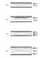
本発明のガスワイピングノズルのスリット配置例を図2に示す。 An example of the slit arrangement of the gas wiping nozzle of the present invention is shown in FIG.
図2(a)は、主スリットとその上に副スリットが配置された第1の例である。本ノズルでは、主スリット幅と副スリット幅の合計スリット幅はノズル幅方向で同一である。主スリットは、ノズル幅方向中央部分は、スリット幅が同一で、両端部側は、ノズル幅方向端部側に向かってスリット幅が徐々に広がるように構成されている。副スリットは、前記主スリットのスリット幅が同一のノズル幅方向中央部分に対応する幅方向中央部分はスリット幅が同一で、両端部側は、ノズル幅方向端部側に向かってスリット幅が徐々に減少するように構成されている。 FIG. 2A is a first example in which a main slit and a sub slit are arranged thereon. In this nozzle, the total slit width of the main slit width and the sub slit width is the same in the nozzle width direction. The main slit has the same slit width at the central portion in the nozzle width direction, and both end portions are configured such that the slit width gradually increases toward the end portion side in the nozzle width direction. The secondary slit has the same slit width at the central portion in the width direction corresponding to the central portion in the nozzle width direction where the slit width of the main slit is the same, and the slit width gradually increases toward both ends in the nozzle width direction. It is configured to decrease.
図2(b)は、主スリットとその上に副スリットが配置された第2の例である。本ノズルでは、主スリットのノズル幅方向中央部分は、スリット幅が同一で、両端部側は、ノズル幅方向端部側に向かってスリット幅が徐々に広がるように構成されている。副ノズルのノズル幅方向のスリット幅は同一である。 FIG. 2B is a second example in which a main slit and a sub slit are arranged thereon. In this nozzle, the central width of the main slit in the nozzle width direction has the same slit width, and both end portions are configured such that the slit width gradually increases toward the end in the nozzle width direction. The slit width in the nozzle width direction of the sub nozzle is the same.
図2(c)は、中央に主スリット及びその上下に副スリットが各々1つずつ配置された例である。中央の主スリットのノズル幅方向中央部分は、スリット幅が同一で、その外側は、ノズル幅方向端部側に向かってスリット幅が徐々に広がるように構成されている。上副スリット、下副スリットのノズル幅方向のスリット幅は同一である。 FIG. 2C shows an example in which a main slit is disposed at the center and one sub slit is disposed above and below the main slit. The central portion of the central main slit in the nozzle width direction has the same slit width, and the outside thereof is configured such that the slit width gradually increases toward the end in the nozzle width direction. The upper sub slit and the lower sub slit have the same slit width in the nozzle width direction.
図2(d)は、中央に主スリット及びその上下に副スリットが各々2つずつ配置された例である。主スリットのノズル幅方向中央部分は、スリット幅が同一で、その外側は、ノズル幅方向端部側に向かってスリット幅が徐々に広がるように構成されている。主スリットの隣に配置された上副スリット、下副スリットは、各々前記主スリットのスリット幅が同一のノズル幅方向中央部分に対応する幅方向中央部分はスリット幅が同一で、その外側は、ノズル幅方向端部側に向かってスリット幅が徐々に減少するように構成され、主スリットのスリット幅、上副ノズルのスリット幅及び下副スリットのスリット幅の合計は、ノズル幅方向で一定である。最も外側に配置された上副スリット、下副スリットは、各々ノズル幅方向のスリット幅は同一である。 FIG. 2D is an example in which two main slits are arranged at the center and two sub slits are arranged above and below the main slit. The central portion of the main slit in the nozzle width direction has the same slit width, and the outside thereof is configured such that the slit width gradually increases toward the end in the nozzle width direction. The upper sub-slit and the lower sub-slit arranged next to the main slit have the same slit width in the central portion in the width direction corresponding to the central portion in the nozzle width direction where the slit width of the main slit is the same. The slit width gradually decreases toward the end in the nozzle width direction, and the sum of the slit width of the main slit, the slit width of the upper sub nozzle, and the slit width of the lower sub slit is constant in the nozzle width direction. is there. The upper sub slit and the lower sub slit arranged on the outermost side have the same slit width in the nozzle width direction.
本発明のガスワイピングノズルは上記構造のものに限定されないが、加工の容易度と効果の観点から、主スリット以外は、主スリットに平行のもの(すなわち、副スリットのノズル幅方向のスリット幅は同一であるもの)、またはノズル外形を平行なもの(すなわち副スリットのスリット幅は、主スリットのノズル端部に向かって増加するスリット幅を打ち消すようにノズル端部に向かって減少するもの。)が好ましく、いずれも副スリットの最小スリット幅は0.2mm以上とするのが好適である。 The gas wiping nozzle of the present invention is not limited to the above structure, but from the viewpoint of ease of processing and effects, except for the main slit, those that are parallel to the main slit (that is, the slit width in the nozzle width direction of the sub slit is One that is the same) or one that is parallel to the nozzle profile (ie, the slit width of the secondary slit decreases toward the nozzle end so as to cancel the slit width increasing toward the nozzle end of the main slit). In any case, the minimum slit width of the sub-slit is preferably 0.2 mm or more.
副スリットから噴射される副噴流は、主スリットから噴射される主噴流の拡散を防止する作用である。副スリットを主スリットの一方の側に配置してもこの作用が奏されるが、主噴流の拡散を防止する作用を向上させるには、副スリットは主スリットの上下に少なくとも一つずつ配置する方が有利である。 The sub-jet injected from the sub-slit has an effect of preventing diffusion of the main jet injected from the main slit. Even if the sub slits are arranged on one side of the main slit, this effect can be achieved. However, in order to improve the effect of preventing the main jet from being diffused, at least one sub slit is arranged above and below the main slit. Is more advantageous.
本発明では、主に主スリットの主噴流によってめっき付着量を制御する。副スリットは、主スリットの主噴流の拡散を防止するために用いられ、主噴流の拡散効果は副スリットの圧力が0.002kgf/cm2程度以上あれば発現される。したがって、副スリットの圧力は通常はこの圧力以上に設定するのが望ましいが、それ以下の使用が特段悪いわけでもないので制限するものではない。 In the present invention, the plating adhesion amount is controlled mainly by the main jet of the main slit. The secondary slit is used to prevent the main jet from diffusing in the main slit, and the diffusion effect of the main jet is manifested when the pressure in the secondary slit is about 0.002 kgf / cm 2 or more. Therefore, it is usually desirable to set the pressure of the sub-slit above this pressure, but it is not limited because the use below that is not particularly bad.
主スリットは、ノズル幅方向のスリット幅が同一でない。スリット幅を変更する変曲点の位置(ノズル幅方向位置)は通常通板する鋼帯幅やエッジオーバーコートの程度に応じて決定することが好ましい。エッジオーバーコートが発生するのは、通常、鋼帯エッジから50〜100mm程度以内である。このことから、例えば平均鋼帯幅1200mmの場合、ノズル幅方向中央のスリット幅が同じ部分(ストレート部)を800mm程度とすれば、鋼帯エッジから200mmの位置が変曲点になり、エッジオーバーコートを抑制することが可能となる。また、主スリットのスリット幅がノズル幅方向外側に向かって大きく部分のスリット幅の増加量(鋼帯エッジのスリット幅とノズル中央のストレート部のスリット幅の差)はエッジオーバーコート量に応じて適宜の大きさに決定する必要がある。エッジオーバーコートの典型量は10g/m2程度である。これを打ち消すためのスリット幅は通常の条件の範囲では0.4mm程度であるため、鋼帯エッジのスリット幅とノズル中央のスリット幅の差が0.4mm程度となるようにノズル形状を設計するのが好適である。 The main slits do not have the same slit width in the nozzle width direction. The position of the inflection point for changing the slit width (position in the nozzle width direction) is preferably determined according to the width of the steel strip that is normally passed through and the degree of edge overcoat. The edge overcoat is usually generated within about 50 to 100 mm from the steel strip edge. From this, for example, in the case of an average steel strip width of 1200 mm, if the portion (straight portion) having the same slit width at the center in the nozzle width direction is about 800 mm, the position of 200 mm from the steel strip edge becomes the inflection point, and the edge over The coating can be suppressed. In addition, the slit width of the main slit increases toward the outside in the nozzle width direction, and the amount of increase in the slit width of the portion (difference between the slit width of the steel strip edge and the slit width of the straight portion in the center of the nozzle) depends on the edge overcoat amount It is necessary to determine an appropriate size. The typical amount of edge overcoat is about 10 g / m 2 . Since the slit width for canceling this is about 0.4 mm in the range of normal conditions, the nozzle shape is designed so that the difference between the slit width at the steel strip edge and the slit width at the center of the nozzle is about 0.4 mm. Is preferred.
連続溶融亜鉛めっき鋼帯製造ラインにおいて、厚さ1.0mm×幅1200mmの鋼帯を本発明例のノズルと比較例のノズルを用いて溶融亜鉛めっき鋼帯を製造し、鋼帯幅方向の付着量分布を調査した。 In a continuous hot-dip galvanized steel strip production line, a hot-dip galvanized steel strip is manufactured from a steel strip having a thickness of 1.0 mm and a width of 1200 mm using the nozzle of the present invention and the nozzle of the comparative example, and adheres in the width direction of the steel strip. The quantity distribution was investigated.
図3(a)は本発明例のノズルである。ノズル幅は2000mm、すなわち主スリット及び副スリットの鋼帯幅方向の幅はいずれも2000mmである。主スリットとその上下に副スリットが各々1つずつ配置されている。主スリットは、幅方向中央の幅800mmの範囲が、スリット幅が0.8mmのストレート部で、その外側はノズルエッジに向かってスリット幅が直線的に増加し、幅1200mm部でのスリット幅は1.2mmで、中央のストレート部のスリット幅より0.4mm大きい。副スリットは、幅方向中央の幅800mmの範囲が、スリット幅が0.8mmのストレート部で、その外側は、主スリットのスリット幅の増加量をキャンセルするようにノズルエッジに向かってスリット幅が直線的に減少するように構成されている(幅1200mm部でのスリット幅は0.6mm)。主スリットのスリット幅、上副スリットのスリット幅及び下副スリットのスリット幅の合計は2.4mmで、ノズル幅方向で同一である。 FIG. 3A shows a nozzle according to an example of the present invention. The nozzle width is 2000 mm, that is, the widths of the main slit and the sub slit in the steel strip width direction are both 2000 mm. A main slit and upper and lower sub-slits are arranged one by one. The main slit is a straight portion having a width of 800 mm in the center in the width direction, and the slit width is 0.8 mm, and the outside of the main slit is linearly increased toward the nozzle edge. 1.2 mm, 0.4 mm larger than the slit width of the central straight part. The secondary slit is a straight portion with a width of 800 mm at the center in the width direction, with a slit width of 0.8 mm. It is configured to linearly decrease (slit width at a width of 1200 mm is 0.6 mm). The sum of the slit width of the main slit, the slit width of the upper sub slit and the slit width of the lower sub slit is 2.4 mm, which is the same in the nozzle width direction.
図3(b)は比較例のノズルである。ノズル幅は2000mm、すなわち主スリット及び副スリットの鋼帯幅方向の幅はいずれも2000mmである。主スリットとその上下に副スリットが各々1つずつ配置されている。主スリット、上下の副スリットとも、全幅にわたってスリット幅が同じで、各々0.8mmである。 FIG. 3B shows a nozzle of a comparative example. The nozzle width is 2000 mm, that is, the widths of the main slit and the sub slit in the steel strip width direction are both 2000 mm. A main slit and upper and lower sub-slits are arranged one by one. The main slit and the upper and lower sub-slits have the same slit width over the entire width, and each is 0.8 mm.
製造条件は、使用したノズル以外はすべて同一の条件とした。主な製造条件は以下の通りである。
ライン速度:120mpm、主スリット圧力:0.7kgf/cm2、副スリット圧力:0.1kgf/cm2、浴温:460℃、ノズル−鋼板距離:10mm、ノズル高さ:400mm
調査結果を図4に示す。本発明例のノズルを用いて製造された溶融亜鉛めっき鋼帯はエッジオーバーコートが少なく、比較例のノズルを用いて製造された溶融亜鉛めっき鋼帯に比べて、鋼帯幅方向の付着量分布の帰一性が大幅に改善されている。
The manufacturing conditions were the same except for the nozzles used. The main manufacturing conditions are as follows.
Line speed: 120 mpm, main slit pressure: 0.7 kgf / cm 2 , sub-slit pressure: 0.1 kgf / cm 2 , bath temperature: 460 ° C., nozzle-steel plate distance: 10 mm, nozzle height: 400 mm
The survey results are shown in FIG. The hot dip galvanized steel strip manufactured using the nozzle of the present invention has less edge overcoat, and compared with the hot dip galvanized steel strip manufactured using the nozzle of the comparative example, the adhesion amount distribution in the steel strip width direction The identities of have been greatly improved.
本発明は、溶融金属めっき浴から連続的に引き上げられる鋼帯の表面に、ガスワイピングノズルからガスを吹き付けて付着金属の厚さを制御する溶融金属めっき鋼帯を製造する際に、エッジオーバーコートの問題を簡易に抑制しつつ、効率的にワイピング力を増大できる方法として使用することができる。 The present invention provides an edge overcoat when manufacturing a molten metal plated steel strip that controls the thickness of the deposited metal by blowing gas from a gas wiping nozzle onto the surface of the steel strip that is continuously pulled up from the molten metal plating bath. It is possible to use as a method that can efficiently increase the wiping force while easily suppressing the above problem.
Claims (4)
Priority Applications (1)
| Application Number | Priority Date | Filing Date | Title |
|---|---|---|---|
| JP2006020363A JP4765643B2 (en) | 2006-01-30 | 2006-01-30 | Method for producing molten metal-plated steel strip and gas wiping nozzle |
Applications Claiming Priority (1)
| Application Number | Priority Date | Filing Date | Title |
|---|---|---|---|
| JP2006020363A JP4765643B2 (en) | 2006-01-30 | 2006-01-30 | Method for producing molten metal-plated steel strip and gas wiping nozzle |
Publications (2)
| Publication Number | Publication Date |
|---|---|
| JP2007197802A JP2007197802A (en) | 2007-08-09 |
| JP4765643B2 true JP4765643B2 (en) | 2011-09-07 |
Family
ID=38452686
Family Applications (1)
| Application Number | Title | Priority Date | Filing Date |
|---|---|---|---|
| JP2006020363A Expired - Fee Related JP4765643B2 (en) | 2006-01-30 | 2006-01-30 | Method for producing molten metal-plated steel strip and gas wiping nozzle |
Country Status (1)
| Country | Link |
|---|---|
| JP (1) | JP4765643B2 (en) |
Family Cites Families (6)
| Publication number | Priority date | Publication date | Assignee | Title |
|---|---|---|---|---|
| JPS52141433A (en) * | 1976-05-21 | 1977-11-25 | Kawasaki Steel Co | Nozzle for controlling adjusting thickness of plated layer |
| JPH0178164U (en) * | 1987-11-11 | 1989-05-25 | ||
| JPH02205663A (en) * | 1989-02-01 | 1990-08-15 | Nisshin Steel Co Ltd | Method for controlling plating deposition of hot dip coating and gas injection nozzle to be used in this method |
| JPH0474857A (en) * | 1990-07-17 | 1992-03-10 | Kobe Steel Ltd | Gas wiping device for hot dip metal coating |
| JP3201260B2 (en) * | 1996-05-14 | 2001-08-20 | 住友金属工業株式会社 | Method for controlling the amount of adhesion of hot-dip coated steel sheet |
| JP2003155550A (en) * | 2001-11-21 | 2003-05-30 | Nkk Corp | Continuous molten metal plating apparatus |
-
2006
- 2006-01-30 JP JP2006020363A patent/JP4765643B2/en not_active Expired - Fee Related
Also Published As
| Publication number | Publication date |
|---|---|
| JP2007197802A (en) | 2007-08-09 |
Similar Documents
| Publication | Publication Date | Title |
|---|---|---|
| US11866829B2 (en) | Device and method for manufacturing a coated metal strip with improved appearance by adjusting a coating thickness using gas jet wiping | |
| JP4696690B2 (en) | Manufacturing method of molten metal plated steel strip | |
| JP5470932B2 (en) | Hot-dip metal-plated steel strip manufacturing equipment and hot-metal-plated steel strip manufacturing method | |
| KR101084934B1 (en) | Method for manufacturing molten-metal plated steel band | |
| JP4862479B2 (en) | Manufacturing method of molten metal plated steel strip | |
| US11802329B2 (en) | Method of producing hot-dip metal coated steel strip and continuous hot-dip metal coating line | |
| JP5169307B2 (en) | Manufacturing method of molten metal plated steel strip | |
| JP5418550B2 (en) | Manufacturing method of molten metal plated steel strip | |
| JP5109671B2 (en) | Hot-dip metal plating equipment and hot-dip steel strip manufacturing method | |
| JP4816105B2 (en) | Manufacturing method of molten metal plated steel strip | |
| JP4765643B2 (en) | Method for producing molten metal-plated steel strip and gas wiping nozzle | |
| JP4677846B2 (en) | Manufacturing method of molten metal plated steel strip | |
| JP5444730B2 (en) | Molten metal plating steel strip production equipment | |
| JP4857906B2 (en) | Manufacturing method of molten metal plated steel strip | |
| JP7111058B2 (en) | Hot-dip metal plated steel strip manufacturing method and continuous hot-dip metal plating equipment | |
| JP5386779B2 (en) | Method and apparatus for manufacturing hot-dip galvanized steel sheet | |
| JP4946167B2 (en) | Manufacturing method of molten metal plated steel strip | |
| JPH01230758A (en) | Method for controlling amount of plated molten metal and gas injection nozzle | |
| JP2011252180A (en) | Method of manufacturing hot dip metal coated steel strip | |
| JP4765641B2 (en) | Manufacturing method of molten metal plated steel strip | |
| JP5287876B2 (en) | Manufacturing method of molten metal plated steel strip | |
| JP6635086B2 (en) | Manufacturing method of hot-dip galvanized steel strip | |
| JPH07102354A (en) | Coating weight controlling device in hot-dip metal plating | |
| JP2010235967A (en) | Apparatus and method for producing hot dip metal coated steel strip | |
| JPH11279736A (en) | Gas wiping method suitable for thick plating |
Legal Events
| Date | Code | Title | Description |
|---|---|---|---|
| A621 | Written request for application examination |
Free format text: JAPANESE INTERMEDIATE CODE: A621 Effective date: 20080925 |
|
| A977 | Report on retrieval |
Free format text: JAPANESE INTERMEDIATE CODE: A971007 Effective date: 20090306 |
|
| TRDD | Decision of grant or rejection written | ||
| A01 | Written decision to grant a patent or to grant a registration (utility model) |
Free format text: JAPANESE INTERMEDIATE CODE: A01 Effective date: 20110517 |
|
| A61 | First payment of annual fees (during grant procedure) |
Free format text: JAPANESE INTERMEDIATE CODE: A61 Effective date: 20110530 |
|
| R150 | Certificate of patent or registration of utility model |
Free format text: JAPANESE INTERMEDIATE CODE: R150 Ref document number: 4765643 Country of ref document: JP Free format text: JAPANESE INTERMEDIATE CODE: R150 |
|
| FPAY | Renewal fee payment (event date is renewal date of database) |
Free format text: PAYMENT UNTIL: 20140624 Year of fee payment: 3 |
|
| R250 | Receipt of annual fees |
Free format text: JAPANESE INTERMEDIATE CODE: R250 |
|
| R250 | Receipt of annual fees |
Free format text: JAPANESE INTERMEDIATE CODE: R250 |
|
| LAPS | Cancellation because of no payment of annual fees |