JP4760065B2 - Control device for automatic transmission - Google Patents
Control device for automatic transmission Download PDFInfo
- Publication number
- JP4760065B2 JP4760065B2 JP2005069616A JP2005069616A JP4760065B2 JP 4760065 B2 JP4760065 B2 JP 4760065B2 JP 2005069616 A JP2005069616 A JP 2005069616A JP 2005069616 A JP2005069616 A JP 2005069616A JP 4760065 B2 JP4760065 B2 JP 4760065B2
- Authority
- JP
- Japan
- Prior art keywords
- control
- clutch
- state
- neutral
- automatic transmission
- Prior art date
- Legal status (The legal status is an assumption and is not a legal conclusion. Google has not performed a legal analysis and makes no representation as to the accuracy of the status listed.)
- Expired - Fee Related
Links
Images


Classifications
-
- F—MECHANICAL ENGINEERING; LIGHTING; HEATING; WEAPONS; BLASTING
- F16—ENGINEERING ELEMENTS AND UNITS; GENERAL MEASURES FOR PRODUCING AND MAINTAINING EFFECTIVE FUNCTIONING OF MACHINES OR INSTALLATIONS; THERMAL INSULATION IN GENERAL
- F16H—GEARING
- F16H61/00—Control functions within control units of change-speed- or reversing-gearings for conveying rotary motion ; Control of exclusively fluid gearing, friction gearing, gearings with endless flexible members or other particular types of gearing
- F16H61/20—Preventing gear creeping ; Transmission control during standstill, e.g. hill hold control
-
- F—MECHANICAL ENGINEERING; LIGHTING; HEATING; WEAPONS; BLASTING
- F16—ENGINEERING ELEMENTS AND UNITS; GENERAL MEASURES FOR PRODUCING AND MAINTAINING EFFECTIVE FUNCTIONING OF MACHINES OR INSTALLATIONS; THERMAL INSULATION IN GENERAL
- F16H—GEARING
- F16H61/00—Control functions within control units of change-speed- or reversing-gearings for conveying rotary motion ; Control of exclusively fluid gearing, friction gearing, gearings with endless flexible members or other particular types of gearing
- F16H61/14—Control of torque converter lock-up clutches
- F16H61/143—Control of torque converter lock-up clutches using electric control means
- F16H2061/145—Control of torque converter lock-up clutches using electric control means for controlling slip, e.g. approaching target slip value
-
- F—MECHANICAL ENGINEERING; LIGHTING; HEATING; WEAPONS; BLASTING
- F16—ENGINEERING ELEMENTS AND UNITS; GENERAL MEASURES FOR PRODUCING AND MAINTAINING EFFECTIVE FUNCTIONING OF MACHINES OR INSTALLATIONS; THERMAL INSULATION IN GENERAL
- F16H—GEARING
- F16H61/00—Control functions within control units of change-speed- or reversing-gearings for conveying rotary motion ; Control of exclusively fluid gearing, friction gearing, gearings with endless flexible members or other particular types of gearing
- F16H61/20—Preventing gear creeping ; Transmission control during standstill, e.g. hill hold control
- F16H2061/207—Preventing gear creeping ; Transmission control during standstill, e.g. hill hold control by neutral control
-
- F—MECHANICAL ENGINEERING; LIGHTING; HEATING; WEAPONS; BLASTING
- F16—ENGINEERING ELEMENTS AND UNITS; GENERAL MEASURES FOR PRODUCING AND MAINTAINING EFFECTIVE FUNCTIONING OF MACHINES OR INSTALLATIONS; THERMAL INSULATION IN GENERAL
- F16H—GEARING
- F16H2200/00—Transmissions for multiple ratios
- F16H2200/003—Transmissions for multiple ratios characterised by the number of forward speeds
- F16H2200/0052—Transmissions for multiple ratios characterised by the number of forward speeds the gear ratios comprising six forward speeds
-
- F—MECHANICAL ENGINEERING; LIGHTING; HEATING; WEAPONS; BLASTING
- F16—ENGINEERING ELEMENTS AND UNITS; GENERAL MEASURES FOR PRODUCING AND MAINTAINING EFFECTIVE FUNCTIONING OF MACHINES OR INSTALLATIONS; THERMAL INSULATION IN GENERAL
- F16H—GEARING
- F16H2200/00—Transmissions for multiple ratios
- F16H2200/20—Transmissions using gears with orbital motion
- F16H2200/2002—Transmissions using gears with orbital motion characterised by the number of sets of orbital gears
- F16H2200/2007—Transmissions using gears with orbital motion characterised by the number of sets of orbital gears with two sets of orbital gears
-
- F—MECHANICAL ENGINEERING; LIGHTING; HEATING; WEAPONS; BLASTING
- F16—ENGINEERING ELEMENTS AND UNITS; GENERAL MEASURES FOR PRODUCING AND MAINTAINING EFFECTIVE FUNCTIONING OF MACHINES OR INSTALLATIONS; THERMAL INSULATION IN GENERAL
- F16H—GEARING
- F16H2200/00—Transmissions for multiple ratios
- F16H2200/20—Transmissions using gears with orbital motion
- F16H2200/202—Transmissions using gears with orbital motion characterised by the type of Ravigneaux set
- F16H2200/2023—Transmissions using gears with orbital motion characterised by the type of Ravigneaux set using a Ravigneaux set with 4 connections
-
- F—MECHANICAL ENGINEERING; LIGHTING; HEATING; WEAPONS; BLASTING
- F16—ENGINEERING ELEMENTS AND UNITS; GENERAL MEASURES FOR PRODUCING AND MAINTAINING EFFECTIVE FUNCTIONING OF MACHINES OR INSTALLATIONS; THERMAL INSULATION IN GENERAL
- F16H—GEARING
- F16H2200/00—Transmissions for multiple ratios
- F16H2200/20—Transmissions using gears with orbital motion
- F16H2200/203—Transmissions using gears with orbital motion characterised by the engaging friction means not of the freewheel type, e.g. friction clutches or brakes
- F16H2200/2046—Transmissions using gears with orbital motion characterised by the engaging friction means not of the freewheel type, e.g. friction clutches or brakes with six engaging means
-
- F—MECHANICAL ENGINEERING; LIGHTING; HEATING; WEAPONS; BLASTING
- F16—ENGINEERING ELEMENTS AND UNITS; GENERAL MEASURES FOR PRODUCING AND MAINTAINING EFFECTIVE FUNCTIONING OF MACHINES OR INSTALLATIONS; THERMAL INSULATION IN GENERAL
- F16H—GEARING
- F16H2312/00—Driving activities
- F16H2312/02—Driving off
-
- F—MECHANICAL ENGINEERING; LIGHTING; HEATING; WEAPONS; BLASTING
- F16—ENGINEERING ELEMENTS AND UNITS; GENERAL MEASURES FOR PRODUCING AND MAINTAINING EFFECTIVE FUNCTIONING OF MACHINES OR INSTALLATIONS; THERMAL INSULATION IN GENERAL
- F16H—GEARING
- F16H2312/00—Driving activities
- F16H2312/14—Going to, or coming from standby operation, e.g. for engine start-stop operation at traffic lights
-
- F—MECHANICAL ENGINEERING; LIGHTING; HEATING; WEAPONS; BLASTING
- F16—ENGINEERING ELEMENTS AND UNITS; GENERAL MEASURES FOR PRODUCING AND MAINTAINING EFFECTIVE FUNCTIONING OF MACHINES OR INSTALLATIONS; THERMAL INSULATION IN GENERAL
- F16H—GEARING
- F16H3/00—Toothed gearings for conveying rotary motion with variable gear ratio or for reversing rotary motion
- F16H3/44—Toothed gearings for conveying rotary motion with variable gear ratio or for reversing rotary motion using gears having orbital motion
- F16H3/62—Gearings having three or more central gears
- F16H3/66—Gearings having three or more central gears composed of a number of gear trains without drive passing from one train to another
- F16H3/663—Gearings having three or more central gears composed of a number of gear trains without drive passing from one train to another with conveying rotary motion between axially spaced orbital gears, e.g. RAVIGNEAUX
-
- F—MECHANICAL ENGINEERING; LIGHTING; HEATING; WEAPONS; BLASTING
- F16—ENGINEERING ELEMENTS AND UNITS; GENERAL MEASURES FOR PRODUCING AND MAINTAINING EFFECTIVE FUNCTIONING OF MACHINES OR INSTALLATIONS; THERMAL INSULATION IN GENERAL
- F16H—GEARING
- F16H59/00—Control inputs to control units of change-speed-, or reversing-gearings for conveying rotary motion
- F16H59/02—Selector apparatus
- F16H59/08—Range selector apparatus
- F16H59/10—Range selector apparatus comprising levers
-
- F—MECHANICAL ENGINEERING; LIGHTING; HEATING; WEAPONS; BLASTING
- F16—ENGINEERING ELEMENTS AND UNITS; GENERAL MEASURES FOR PRODUCING AND MAINTAINING EFFECTIVE FUNCTIONING OF MACHINES OR INSTALLATIONS; THERMAL INSULATION IN GENERAL
- F16H—GEARING
- F16H59/00—Control inputs to control units of change-speed-, or reversing-gearings for conveying rotary motion
- F16H59/14—Inputs being a function of torque or torque demand
- F16H59/18—Inputs being a function of torque or torque demand dependent on the position of the accelerator pedal
-
- F—MECHANICAL ENGINEERING; LIGHTING; HEATING; WEAPONS; BLASTING
- F16—ENGINEERING ELEMENTS AND UNITS; GENERAL MEASURES FOR PRODUCING AND MAINTAINING EFFECTIVE FUNCTIONING OF MACHINES OR INSTALLATIONS; THERMAL INSULATION IN GENERAL
- F16H—GEARING
- F16H59/00—Control inputs to control units of change-speed-, or reversing-gearings for conveying rotary motion
- F16H59/50—Inputs being a function of the status of the machine, e.g. position of doors or safety belts
- F16H59/56—Inputs being a function of the status of the machine, e.g. position of doors or safety belts dependent on signals from the main clutch
-
- F—MECHANICAL ENGINEERING; LIGHTING; HEATING; WEAPONS; BLASTING
- F16—ENGINEERING ELEMENTS AND UNITS; GENERAL MEASURES FOR PRODUCING AND MAINTAINING EFFECTIVE FUNCTIONING OF MACHINES OR INSTALLATIONS; THERMAL INSULATION IN GENERAL
- F16H—GEARING
- F16H61/00—Control functions within control units of change-speed- or reversing-gearings for conveying rotary motion ; Control of exclusively fluid gearing, friction gearing, gearings with endless flexible members or other particular types of gearing
- F16H61/14—Control of torque converter lock-up clutches
Abstract
Description
本発明は、自動変速機の制御装置に関し、特に、ニュートラル制御から復帰して車両を発進させる際の制御装置に関する。 The present invention relates to a control device for an automatic transmission, and more particularly to a control device for returning from neutral control and starting a vehicle.
自動変速機に電磁弁を搭載し、外部から電気信号を入力して変速操作に関する変数、たとえば、変速段、油圧レベル、変速操作の時定数やタイミング等をECU(Electronic Control Unit)により調整する自動変速機が実用化されている。このようなECUにより自動変速機の運転状態を種々の状態へと確実かつ速やかに移行可能である。また、ECUには、CPU(Central Processing Unit)が組み込まれているので、プログラムにより制御が可能であるから、プログラムや種々の定数の変更を通じて、自動変速機の運転状態をきめ細かく設定すれば、車両の走行状態やエンジンの負荷状態に対応させて最適な性能を自動変速機から引き出すことが可能である。ここで、車両の走行状態とは、車速やステアリング操作、加速減速の頻度やそのレベル、路面状態等であり、エンジンの負荷状態とは、エンジンの回転数、スロットル開度、アクセルペダル踏み込み量、エンジンや自動変速機の入出力軸のトルク等である。 The automatic transmission is equipped with a solenoid valve, and automatically adjusts variables related to gear shifting operations, such as gear speed, hydraulic level, time constants and timing of gear shifting operations, etc., by inputting an electrical signal from outside. A transmission has been put into practical use. With such an ECU, the operating state of the automatic transmission can be reliably and quickly shifted to various states. Moreover, since the ECU (Central Processing Unit) is incorporated in the ECU, it can be controlled by a program. Therefore, if the operating state of the automatic transmission is set finely through changes in the program and various constants, the vehicle The optimum performance can be extracted from the automatic transmission in accordance with the running state of the vehicle and the load state of the engine. Here, the running state of the vehicle is the vehicle speed, steering operation, acceleration / deceleration frequency and level, road surface condition, etc., and the engine load state is the engine speed, throttle opening, accelerator pedal depression amount, This is the torque of the input and output shafts of engines and automatic transmissions.
さらに、自動変速機に内蔵された係合要素(クラッチやブレーキ)に供給される油圧レベルは、車両の走行状態やエンジンの負荷状態に適合させてきめ細かく調整される。このように調整することにより、変速ショックの抑制と係合要素の損耗の軽減を両立させて、速やかで円滑な変速を達成することができる。 Furthermore, the hydraulic pressure level supplied to the engagement elements (clutch and brake) incorporated in the automatic transmission is finely adjusted to suit the running state of the vehicle and the load state of the engine. By adjusting in this way, it is possible to achieve both a reduction in shift shock and a reduction in wear of the engagement element, and a quick and smooth shift can be achieved.
このような自動変速機は、エンジンとトルクコンバータ等を介して繋がるとともに複数の動力伝達経路を有してなる変速機構を有して構成され、たとえば、アクセル開度および車速に基づいて自動的に動力伝達経路の切り換えを行なう、すなわち自動的に変速比(走行速度段)の切り換えを行なうように構成される。一般的に、自動変速機を有した車両には運転者により操作されるシフトレバーが設けられ、シフトレバー操作に基づいて変速ポジション(たとえば、後進走行ポジション、ニュートラルポジション、前進走行ポジション)が設定され、このように設定された変速ポジション内(通常は、前進走行ポジション内)において自動変速制御が行なわれる。 Such an automatic transmission has a transmission mechanism that is connected to an engine via a torque converter or the like and has a plurality of power transmission paths. For example, the automatic transmission is automatically based on the accelerator opening and the vehicle speed. The power transmission path is switched, that is, the transmission gear ratio (travel speed stage) is automatically switched. Generally, a vehicle having an automatic transmission is provided with a shift lever operated by a driver, and a shift position (for example, a reverse travel position, a neutral position, a forward travel position) is set based on the shift lever operation. The automatic shift control is performed in the shift position set in this way (usually, in the forward travel position).
このような自動変速機を有した車両において、前進走行ポジションが設定されて車両が停止している状態では、アイドリング回転するエンジンからの駆動力がトルクコンバータを介して変速機に伝達され、これが車輪に伝達されるため、いわゆるクリープ現象が発生する。クリープ現象は、登坂路での停車からの発進をスムーズに行なわせることができるなど、所定条件下では非常に有用なのであるが、車両を停止保持したいときには不要な現象であり、車両のブレーキを作動させてクリープ力を抑えるようになっている。すなわち、エンジンからのクリープ力をブレーキにより抑えるようになっており、その分エンジンの燃費が低下するという問題がある。 In a vehicle having such an automatic transmission, in a state where the forward traveling position is set and the vehicle is stopped, the driving force from the idling engine is transmitted to the transmission via the torque converter, which is the wheel. Therefore, a so-called creep phenomenon occurs. Creep phenomenon is very useful under certain conditions, such as smooth starting from a stop on an uphill road, but it is an unnecessary phenomenon when you want to keep the vehicle stopped, and it activates the vehicle brake To suppress the creep force. That is, the creep force from the engine is suppressed by the brake, and there is a problem that the fuel consumption of the engine is reduced accordingly.
このようなことから、前進走行ポジションにおいて、ブレーキペダルが踏み込まれてブレーキが作動されるとともにアクセルがほぼ全閉となって車両が停止している状態では、前進走行ポジションのまま前進クラッチを解放させて、変速機をニュートラルに近いニュートラル状態として、燃費の向上を図ることが提案されている。 For this reason, in the forward travel position, when the brake pedal is depressed and the brake is activated, and the accelerator is almost fully closed and the vehicle is stopped, the forward clutch is released in the forward travel position. Thus, it has been proposed to improve the fuel consumption by setting the transmission to a neutral state close to neutral.
このようなニュートラル制御といわれる技術や、車両が停止状態から速やかに発進する状態における制御技術などが多く開示されている。特に、トルクコンバータの入力側と出力側とを直結可能とするロックアップクラッチを制御して、入力側のポンプ回転速度(エンジン回転速度に対応)と出力側のタービン回転速度との回転差に応じて、そのロックアップクラッチの係合力を所定の状態にフィードバック制御し(スリップ制御し)、これによってトルクコンバータのスリップ状態を適正に制御して振動および騒音の発生を防止するととともに、車両の発進性能の向上を図るようにした技術が知られている。 There are many disclosures of such a technique called neutral control and a control technique in a state in which the vehicle quickly starts from a stopped state. In particular, the lockup clutch that enables direct connection between the input side and the output side of the torque converter is controlled to respond to the rotational difference between the pump speed on the input side (corresponding to the engine speed) and the turbine speed on the output side. Thus, the engagement force of the lock-up clutch is feedback controlled to a predetermined state (slip control), thereby properly controlling the slip state of the torque converter to prevent the generation of vibration and noise, and the vehicle start performance There is known a technique for improving the above.
このように、高度な電子制御によって、ロックアップクラッチによる機械的な動力伝達とトルクコンバータによる動力伝達との動力伝達配分を走行状態に応じて、きめ細かく制御することにより、伝達効率を大幅に高めている。この制御においては、中間モード(ロックアップクラッチに微小な滑りを与えるスリップ制御)を低車速域まで広げて設定し、ロックアップ領域をより拡大するものである。 In this way, through advanced electronic control, the power transmission distribution between the mechanical power transmission by the lock-up clutch and the power transmission by the torque converter is finely controlled according to the driving state, thereby greatly increasing the transmission efficiency. Yes. In this control, the intermediate mode (slip control for giving a minute slip to the lockup clutch) is set to be extended to the low vehicle speed range, and the lockup range is further expanded.
特開2005−3193号公報(特許文献1)は、ニュートラル制御からの復帰時にロックアップクラッチをスリップ制御して、車両を発進させる車両用ロックアップクラッチの制御装置を開示する。この車両用ロックアップクラッチの制御装置は、ロックアップクラッチ付流体伝動装置をエンジンの出力側に有する車両において、ロックアップクラッチを制御するための車両用ロックアップクラッチの制御装置であって、ロックアップクラッチ付流体伝動装置の出力側には自動変速機が連結され、車両の停止時には自動変速機内の動力伝達経路を解放するための油圧式摩擦係合装置を解放するニュートラル制御手段と、ニュートラル制御手段による自動変速機の動力伝達経路の解放制御が実行されている間は油圧式摩擦係合装置の元圧を所定圧高めるが、解放制御が終了されると元圧を緩やかに低下させて復帰させる元圧制御手段と、車両の発進に際してロックアップクラッチをスリップ状態とするロックアップクラッチ制御手段とを含み、ロックアップクラッチの制御に用いられる制御油圧は元圧制御手段によって制御される元圧から調圧されることを特徴とする。 Japanese Patent Laying-Open No. 2005-3193 (Patent Document 1) discloses a control device for a vehicle lock-up clutch that starts the vehicle by slip-controlling the lock-up clutch when returning from neutral control. This vehicle lock-up clutch control device is a vehicle lock-up clutch control device for controlling a lock-up clutch in a vehicle having a fluid transmission device with a lock-up clutch on the output side of the engine. An automatic transmission is connected to the output side of the fluid transmission with clutch, and a neutral control means for releasing a hydraulic friction engagement device for releasing a power transmission path in the automatic transmission when the vehicle is stopped, and a neutral control means While the release control of the power transmission path of the automatic transmission is executed by the above, the original pressure of the hydraulic friction engagement device is increased by a predetermined pressure, but when the release control is finished, the original pressure is gradually reduced to return. Original pressure control means, and lockup clutch control means for making the lockup clutch slip when the vehicle starts Control hydraulic pressure used to control the lock-up clutch is characterized in that it is pressure regulated from the original pressure, which is controlled by the original pressure control means.
この車両用ロックアップクラッチの制御装置によると、ニュートラル制御から復帰して車両が発進する際に、ロックアップクラッチ制御手段によりロックアップクラッチがスリップ状態とされるので、車両の発進時において、エンジンからの伝達トルクが、流体伝動装置を介して後段に伝達されるのに並行して、ロックアップクラッチを介しても後段に伝達されることから、流体伝動装置だけで動力を伝達する従来の発進時に比較して、車両発進時におけるエンジンの回転速度上昇が抑制されるので、良い燃費が車両発進時に得られる(以下、このように車両を発進させることをスリップスタートと記載する)。さらに、元圧制御手段により、ニュートラル制御中には所定圧高められていた元圧がそのニュートラル制御の終了に伴ってその元圧が緩やかに低下させられてニュートラル制御前の値に復帰させられることから、そのニュートラル制御直後の車両発進時においてロックアップクラッチ制御手段により、流体伝動装置のロックアップクラッチがスリップ状態となるように制御されるとき、そのロックアップクラッチのスリップ制御に用いる元圧の急変が防止されるので、その元圧の急変に起因するスリップ制御に乱れが好適に解消される。
しかしながら、特許文献1に開示された車両用ロックアップクラッチの制御装置によると、ニュートラル制御からの復帰中にアクセルペダルが踏まれてもスリップスタートされる場合がある。ニュートラル制御からの復帰時においては、解放されていた前進クラッチ(入力クラッチやフォワードクラッチともいわれる)が係合される。この前進クラッチの係合初期にスリップスタートを実行すると、タービントルクが大きく変化してしまい、前進クラッチの係合特性が悪化する。これにより、係合ショックが発生するという問題や耐久性の問題が発生する。
However, according to the control device for a lockup clutch for a vehicle disclosed in
本発明は、上述の課題を解決するためになされたものであって、その目的は、ニュートラル制御からの復帰時において、係合要素の耐久性を保ちつつ、係合ショックの発生を抑制する、自動変速機の制御装置を提供することである。 The present invention has been made in order to solve the above-described problems, and its purpose is to suppress the occurrence of an engagement shock while maintaining the durability of the engagement element when returning from the neutral control. It is to provide a control device for an automatic transmission.
第1の発明に係る自動変速機の制御装置は、車両の発進時に係合される係合要素を有する自動変速機を制御する。自動変速機は、ロックアップクラッチを備えたトルクコンバータと変速機構とから構成される。この制御装置は、前進走行ポジションで車両の状態が予め定められた条件を満足して停止した場合に、係合要素を解放するように変速機構を制御するためのニュートラル制御実行手段と、車両の状態が別途定められた条件を満足した場合に、係合要素を係合するように変速機構を制御するためのニュートラル制御復帰手段と、車両を発進させる際に、ロックアップクラッチを係合状態およびスリップ状態のいずれかの状態にするように、ロックアップクラッチを制御するための発進制御手段と、ニュートラル制御からの復帰状態を検知するための検知手段と、ニュートラル制御からの復帰状態に基づいて、発進制御手段によりロックアップクラッチを制御するか否かを決定するための決定手段とを含む。 A control device for an automatic transmission according to a first invention controls an automatic transmission having an engaging element that is engaged when the vehicle starts. The automatic transmission includes a torque converter including a lock-up clutch and a transmission mechanism. The control device includes a neutral control execution means for controlling the speed change mechanism so as to release the engagement element when the vehicle state stops at a forward traveling position while satisfying a predetermined condition, And a neutral control return means for controlling the transmission mechanism to engage the engaging element when the state satisfies a separately defined condition, and when the vehicle is started, the lockup clutch is engaged and Based on the start control means for controlling the lockup clutch, the detection means for detecting the return state from the neutral control, and the return state from the neutral control so as to be in any state of the slip state, Determining means for determining whether or not the lockup clutch is controlled by the start control means.
第1の発明によると、トルクコンバータからの出力トルクであるタービントルク(TT)は、エンジントルクTE(ポンプトルクTPと同じとする)およびトルクコンバータのトルク比t(t>1)を用いて、以下のように表わされる。ロックアップクラッチが解放状態である場合においてはTT=t×TE、ロックアップクラッチが解放状態でない場合においてはロックアップクラッチによる伝達トルクをTCとしてTT=t×(TE−TC)+TC=T×TE+(1−t)×TCとなる。このため、スリップスタートするときの方が{(1−t)×TC}の分だけタービントルクTTが変動する。タービントルクTTが変速機構への入力トルクになるとともに、車両の発進時に係合される係合要素であって、ニュートラル制御の実行時に解放状態とされ車両の発進時に係合状態にされる前進クラッチが後段に伝達するトルクになる。このトルクが前進クラッチが完全に係合するまでに変動すると、タービントルクTTが大きく変化した場合には前進クラッチが滑って磨耗しやすくなり、タービントルクTTが小さく変化した場合には前進クラッチが急激に係合されてショックが発生する。このため、検知手段によりニュートラル制御からの復帰状態(前進クラッチの係合状態)を検知して、前進クラッチが十分に係合していると判断されるとスリップスタートを許可するが、前進クラッチが十分に係合していると判断されないとスリップスタートを許可しない。その結果、ニュートラル制御からの復帰時において、係合要素の耐久性を保ちつつ、係合ショックの発生を抑制する、自動変速機の制御装置を提供することができる。 According to the first invention, the turbine torque (TT), which is the output torque from the torque converter, uses the engine torque TE (same as the pump torque TP) and the torque ratio t (t> 1) of the torque converter, It is expressed as follows. When the lockup clutch is in the released state, TT = t × TE, and when the lockup clutch is not in the released state, TC = T × (TE−TC) + TC = T × TE + (1-t) × TC. Therefore, the turbine torque TT varies by {(1-t) × TC} when the slip start is performed. A forward clutch that is an engaging element that is engaged when the vehicle starts, and that is released when the neutral control is executed and is engaged when the vehicle starts, while the turbine torque TT becomes an input torque to the speed change mechanism. Becomes the torque transmitted to the subsequent stage. If this torque fluctuates until the forward clutch is completely engaged, the forward clutch is likely to slip and wear when the turbine torque TT changes greatly, and the forward clutch suddenly increases when the turbine torque TT changes small. To generate a shock. For this reason, the detection means detects the return state from the neutral control (engagement state of the forward clutch), and when it is determined that the forward clutch is sufficiently engaged, the slip start is permitted. The slip start is not permitted unless it is determined that the engagement is sufficient. As a result, it is possible to provide a control device for an automatic transmission that suppresses the occurrence of an engagement shock while maintaining the durability of the engagement element when returning from the neutral control.
第2の発明に係る自動変速機の制御装置においては、第1の発明の構成に加えて、決定手段は、ニュートラル制御からの復帰が初期状態であると、発進制御手段による制御を禁止するように決定するための手段を含む。 In the automatic transmission control device according to the second invention, in addition to the configuration of the first invention, the determining means prohibits the control by the start control means when the return from the neutral control is in the initial state. Means for determining.
第2の発明によると、ニュートラル制御からの復帰が初期状態であって前進クラッチが十分に係合していない場合にはスリップスタートを禁止して、タービントルクTTの変動による前進クラッチに与える影響を抑制することができる。 According to the second aspect of the invention, when the return from the neutral control is in the initial state and the forward clutch is not sufficiently engaged, the slip start is prohibited and the influence on the forward clutch due to the fluctuation of the turbine torque TT is inhibited. Can be suppressed.
第3の発明に係る自動変速機の制御装置においては、第1の発明の構成に加えて、決定手段は、ニュートラル制御からの復帰が初期状態を経過していると、発進制御手段による制御を実行するように決定するための手段を含む。 In the automatic transmission control device according to the third invention, in addition to the configuration of the first invention, the determining means performs the control by the start control means when the return from the neutral control has passed the initial state. Means for deciding to perform.
第3の発明によると、ニュートラル制御からの復帰が初期状態を経過していて前進クラッチが十分に係合している場合にはスリップスタートを許可して、速やかに車両を発進させることができる。 According to the third invention, when the return from the neutral control has passed the initial state and the forward clutch is sufficiently engaged, the slip start is permitted and the vehicle can be started immediately.
第4の発明に係る自動変速機の制御装置においては、第1の発明の構成に加えて、決定手段は、係合要素の係合状態に基づいて、ニュートラル制御からの復帰が初期状態であるか、初期状態を経過しているのかを判断して、ニュートラル制御からの復帰が初期状態を経過していると、発進制御手段による制御を実行するように決定するための手段を含む。 In the control device for an automatic transmission according to the fourth invention, in addition to the configuration of the first invention, the determining means is in an initial state of returning from the neutral control based on the engagement state of the engagement element. Or a means for determining whether or not the control by the start control means is to be executed when the return from the neutral control has passed the initial state.
第4の発明によると、車両の発進時に係合状態にされる前進クラッチが十分に係合していない場合には初期状態であると、前進クラッチが十分に係合している場合には初期状態を経過していると判断して、スリップスタートの許否を決定することができる。 According to the fourth invention, when the forward clutch that is engaged when the vehicle is started is not sufficiently engaged, the initial state is established. When the forward clutch is sufficiently engaged, the initial state is established. It is possible to determine whether or not slip start is permitted by determining that the state has passed.
第5の発明に係る自動変速機の制御装置においては、第1の発明の構成に加えて、決定手段は、ニュートラル制御からの復帰を開始してから予め定められた時間が経過すると、初期状態を経過していると判断して、発進制御手段による制御を実行するように決定するための手段を含む。 In the automatic transmission control apparatus according to the fifth aspect of the invention, in addition to the configuration of the first aspect of the invention, the determining means is in an initial state when a predetermined time has elapsed since the start of the return from the neutral control. And means for determining to execute the control by the start control means.
第5の発明によると、ニュートラル制御の復帰から前進クラッチを係合させるための油圧が供給され前進クラッチが係合されるが、この応答に遅れ時間が生じるので、ニュートラル制御からの復帰を開始してから予め定められた時間が経過すると、初期状態を経過していると判断することができる。 According to the fifth aspect of the invention, the hydraulic pressure for engaging the forward clutch is supplied from the return of the neutral control and the forward clutch is engaged. However, since this response has a delay time, the return from the neutral control is started. When a predetermined time has elapsed since then, it can be determined that the initial state has elapsed.
第6の発明に係る自動変速機の制御装置においては、第1の発明の構成に加えて、決定手段は、タービン回転数が予め定められた回転数以下になると、初期状態を経過していると判断して、発進制御手段による制御を実行するように決定するための手段を含む。 In the automatic transmission control device according to the sixth aspect of the invention, in addition to the configuration of the first aspect, the determining means has passed the initial state when the turbine rotational speed is equal to or lower than a predetermined rotational speed. And a means for determining to execute the control by the start control means.
第6の発明によると、ニュートラル制御の復帰から前進クラッチを係合させるにしたがって、タービン回転数NTが低下するので、ニュートラル制御からの復帰を開始してからタービン回転数NTの変化を検知してタービン回転数NTが予め定められた回転数以下になると、初期状態を経過していると判断することができる。 According to the sixth aspect of the invention, as the forward clutch is engaged from the return of the neutral control, the turbine speed NT decreases, so the change in the turbine speed NT is detected after the return from the neutral control is started. When the turbine rotational speed NT is equal to or lower than a predetermined rotational speed, it can be determined that the initial state has elapsed.
以下、図面を参照しつつ、本発明の実施の形態について説明する。以下の説明では、同一の部品には同一の符号を付してある。それらの名称および機能も同じである。したがってそれらについての詳細な説明は繰返さない。 Hereinafter, embodiments of the present invention will be described with reference to the drawings. In the following description, the same parts are denoted by the same reference numerals. Their names and functions are also the same. Therefore, detailed description thereof will not be repeated.
<第1の実施の形態>
図1を参照して、本発明の第1の実施の形態に係る自動変速機の制御装置を搭載した車両について説明する。この車両は、FF(Front engine Front drive)車両である。なお、本実施の形態に係る自動変速機の制御装置を搭載した車両は、FF以外の車両であってもよい。
<First Embodiment>
A vehicle equipped with a control device for an automatic transmission according to a first embodiment of the present invention will be described with reference to FIG. This vehicle is an FF (Front engine Front drive) vehicle. The vehicle equipped with the automatic transmission control device according to the present embodiment may be a vehicle other than FF.
車両は、エンジン1000と、トランスミッション2000と、トランスミッション2000の一部を構成するプラネタリーギヤユニット3000と、トランスミッション2000の一部を構成する油圧回路4000と、ディファレンシャルギヤ5000と、ドライブシャフト6000と、前輪7000と、ECU8000とを含む。
The vehicle includes an
エンジン1000は、インジェクタ(図示せず)から噴射された燃料と空気との混合気を、シリンダの燃焼室内で燃焼させる内燃機関である。燃焼によりシリンダ内のピストンが押し下げられて、クランクシャフトが回転させられる。なお、内燃機関の代わりに外燃機関を用いても良い。また、エンジン1000の代わりに回転電機などを用いてもよい。
トランスミッション2000は、所望のギヤ段を形成することにより、クランクシャフトの回転数を所望の回転数に変速する。トランスミッション2000の出力ギヤは、ディファレンシャルギヤ5000と噛合っている。プラネタリーギヤユニット3000については、後で詳述する。
ディファレンシャルギヤ5000にはドライブシャフト6000がスプライン嵌合などによって連結されている。ドライブシャフト6000を介して、左右の前輪7000に動力が伝達される。
A
ECU8000には、車速センサ8002と、シフトレバー8004のポジションスイッチ8005と、アクセルペダル8006のアクセル開度センサ8007と、ブレーキペダル8008に設けられたストップランプスイッチ8009と、油温センサ8010とがハーネスなどを介して接続されている。
The
車速センサ8002は、ドライブシャフト6000の回転数から車両の車速を検出し、検出結果を表す信号をECU8000に送信する。シフトレバー8004の位置は、ポジションスイッチ8005により検出され、検出結果を表す信号がECU8000に送信される。シフトレバー8004の位置に対応して、トランスミッション2000のギヤ段が自動で形成される。また、運転者の操作に応じて、運転者が任意のギヤ段を選択できるマニュアルシフトモードを選択できるように構成してもよい。
The
アクセル開度センサ8007は、アクセルペダル8006の開度を検出し、検出結果を表す信号をECU8000に送信する。ストップランプスイッチ8009は、ブレーキペダル8008のオン/オフ状態を検出し、検出結果を表す信号をECU8000に送信する。なお、ストップランプスイッチ8009の代わりに、ブレーキペダル8008のストローク量を検出するストロークセンサを設けてもよい。油温センサ8010は、トランスミッション2000のATF(Automatic Transmission Fluid)の温度を検出し、検出結果を表す信号をECU8000に送信する。
The
ECU8000は、車速センサ8002、ポジションスイッチ8005およびアクセル開度センサ8007、ストップランプスイッチ8009、油温センサ8010などから送られてきた信号、ROM(Read Only Memory)に記憶されたマップおよびプログラムに基づいて、車両が所望の走行状態となるように、機器類を制御する。
図2を参照して、プラネタリーギヤユニット3000について説明する。プラネタリーギヤユニット3000は、クランクシャフトに連結された入力軸3100を有するトルクコンバータ3200に接続されている。プラネタリーギヤユニット3000は、遊星歯車機構の第1セット3300と、遊星歯車機構の第2セット3400と、出力ギヤ3500と、ギヤケース3600に固定されたB1ブレーキ3610、B2ブレーキ3620およびB3ブレーキ3630と、C1クラッチ3640およびC2クラッチ3650と、ワンウェイクラッチF3660とを含む。
The
第1セット3300は、シングルピニオン型の遊星歯車機構である。第1セット3300は、サンギヤS(UD)3310と、ピニオンギヤ3320と、リングギヤR(UD)3330と、キャリアC(UD)3340とを含む。
The
サンギヤS(UD)3310は、トルクコンバータ3200の出力軸3210に連結されている。ピ二オンギヤ3320は、キャリアC(UD)3340に回転自在に支持されている。ピ二オンギヤ3320は、サンギヤS(UD)3310およびリングギヤR(UD)3330と係合している。
Sun gear S (UD) 3310 is coupled to
リングギヤR(UD)3330は、B3ブレーキ3630によりギヤケース3600に固定される。キャリアC(UD)3340は、B1ブレーキ3610によりギヤケース3600に固定される。
Ring gear R (UD) 3330 is fixed to
第2セット3400は、ラビニヨ型の遊星歯車機構である。第2セット3400は、サンギヤS(D)3410と、ショートピニオンギヤ3420と、キャリアC(1)3422と、ロングピ二オンギヤ3430と、キャリアC(2)3432と、サンギヤS(S)3440と、リングギヤR(1)(R(2))3450とを含む。
The
サンギヤS(D)3410は、キャリアC(UD)3340に連結されている。ショートピニオンギヤ3420は、キャリアC(1)3422に回転自在に支持されている。ショートピニオンギヤ3420は、サンギヤS(D)3410およびロングピ二オンギヤ3430と係合している。キャリアC(1)3422は、出力ギヤ3500に連結されている。
Sun gear S (D) 3410 is coupled to carrier C (UD) 3340.
ロングピ二オンギヤ3430は、キャリアC(2)3432に回転自在に支持されている。ロングピ二オンギヤ3430は、ショートピニオンギヤ3420、サンギヤS(S)3440およびリングギヤR(1)(R(2))3450と係合している。キャリアC(2)3432は、出力ギヤ3500に連結されている。
サンギヤS(S)3440は、C1クラッチ3640によりトルクコンバータ3200の出力軸3210に連結される。リングギヤR(1)(R(2))3450は、B2ブレーキ3620により、ギヤケース3600に固定され、C2クラッチ3650によりトルクコンバータ3200の出力軸3210に連結される。また、リングギヤR(1)(R(2))3450は、ワンウェイクラッチF3660に連結されており、1速ギヤ段の駆動時に回転不能となる。
Sun gear S (S) 3440 is coupled to
図3に、各変速ギヤ段と、各クラッチおよび各ブレーキの作動状態との関係を表した作動表を示す。「○」は係合を表している。「×」は解放を表している。「◎」はエンジンブレーキ時のみの係合を表している。「△」は駆動時のみの係合を表している。この作動表に示された組合わせで各ブレーキおよび各クラッチを作動させることにより、1速〜6速の前進ギヤ段と、後進ギヤ段が形成される。 FIG. 3 shows an operation table showing the relationship between each gear position and the operation state of each clutch and each brake. “◯” represents engagement. “X” represents release. “◎” represents engagement only during engine braking. “Δ” represents engagement only during driving. By operating each brake and each clutch with the combination shown in this operation table, a forward gear stage of 1st to 6th speed and a reverse gear stage are formed.
B2ブレーキ3620と並列にワンウェイクラッチF3660が設けられているため、作動表に「◎」で示されているように、1速ギヤ段(1ST)形成時のエンジン側からの駆動状態(加速時)にはB2ブレーキ3620を係合させる必要は無い。本実施の形態において、ワンウェイクラッチF3660は、1速ギヤ段の駆動時には、リングギヤR(1)(R(2))3450の回転を防止する。エンジンブレーキを利かせる場合、ワンウェイクラッチF3660は、リングギヤR(1)(R(2))3450の回転を防止しない。
Since the one-way clutch F3660 is provided in parallel with the
トルクコンバータ3200は、入力軸と出力軸とを直結状態にするロックアップクラッチ3203と、入力軸側のポンプ羽根車3201と、出力軸側のタービン羽根車3202と、ワンウェイクラッチ3204を有し、トルク増幅機能を発現するステータ3205とから構成される。トルクコンバータ3200と自動変速機とは、回転軸により接続される。トルクコンバータ3200の出力軸回転数NT(タービン回転数NT)は、タービン回転数センサにより検知される。自動変速機の出力軸回転数NOUTは、出力軸回転数センサにより検知される。
The
図3に示した作動表によると、摩擦要素であるクラッチ要素(図中のC1〜C2)や、ブレーキ要素(B1〜B3)、ワンウェイクラッチ要素(F)が、どのギヤ段の場合に係合および解放されるかを示している。車両の発進時に使用される1速時には、クラッチ要素(C1)、ワンウェイクラッチ要素(F)が係合する。これらのクラッチ要素の中で、特に、C1クラッチ3640を前進クラッチや入力クラッチやフォワードクラッチとも呼ばれ、図3の作動表に示すように、パーキング(P)ポジション、後進走行(R)ポジション、ニュートラル(N)ポジション以外の、車両が前進するための変速段を構成する際に必ず係合状態で使用される。 According to the operation table shown in FIG. 3, the clutch elements (C1 to C2 in the figure), the brake elements (B1 to B3), and the one-way clutch element (F) that are friction elements are engaged at any gear stage. And shows what will be released. At the first speed used when the vehicle starts, the clutch element (C1) and the one-way clutch element (F) are engaged. Among these clutch elements, in particular, the C1 clutch 3640 is also called a forward clutch, an input clutch, or a forward clutch. As shown in the operation table of FIG. 3, the parking (P) position, the reverse travel (R) position, the neutral (N) It is always used in the engaged state when configuring a shift stage for the vehicle to move forward, other than the position.
前進走行(D)ポジションであって、車両の状態が予め定められた条件(アクセルオフかつブレーキオンかつブレーキマスタシリンダ圧が所定値以上かつ車速が所定値以下)を満足して停止状態にあると判定されると、C1クラッチ3640を解放して所定のスリップ状態にして、ニュートラルに近い状態にする制御をニュートラル制御という。 When the vehicle is in the forward running (D) position and the vehicle is in a stopped state that satisfies a predetermined condition (accelerator off and brake on, the brake master cylinder pressure is equal to or higher than a predetermined value, and the vehicle speed is equal to or lower than a predetermined value) When it is determined, the control for releasing the C1 clutch 3640 to bring it into a predetermined slip state and bringing it into a state close to neutral is called neutral control.
本実施の形態に係る制御装置であるECU8000は、ニュートラル制御からの復帰時においてトルクコンバータ3200のロックアップクラッチ3206をスリップ状態にしてスリップスタートさせるが、C1クラッチ3640が係合されるまでの間においては、このスリップスタートを禁止することが特徴である。以下、この特徴についてフローチャートを用いて説明する。
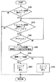
図4を参照して、本実施の形態に係る制御装置であるECU8000で実行されるプログラムの制御構造について説明する。なお、以下に示すフローチャートにより表わされるプログラムは、所定のサイクルタイムで繰り返し実行される。
With reference to FIG. 4, a control structure of a program executed by
ステップ(以下、ステップをSと略す。)100にて、ECU8000は、ニュートラル制御実行モードであるか否かを判断する。車両が停止して、アクセルペダルが踏まれていなくて、ブレーキが作動している等の条件が成立するとニュートラル制御実行モードに入りC1クラッチ3640が解放される。ニュートラル制御実行モードであると(S100にてYES)、処理はS200へ移される。もしそうでないと(S100にてNO)、この処理は終了する。
In step (hereinafter, step is abbreviated as S) 100,
S200にて、ECU8000は、ニュートラル制御復帰モードであるか否かを判断する。車両が停止しているが、ブレーキが作動していない(ブレーキペダルが踏まれなくなった)等の条件が成立するとニュートラル制御復帰モードに入りC1クラッチ3640の係合が開始される。ニュートラル制御復帰モードであると(S200にてYES)、処理はS300へ移される。もしそうでないと(S200にてNO)、この処理は終了する。
In S200,
S300にて、ECU8000は、ニュートラル制御復帰モード中であってアクセルペダルが踏まれてアクセルオンにされたか否かを判断する。アクセルオンであると判断されると(S300にてYES)、処理はS400へ移される。もしそうでないと(S300にてNO)、処理はS200へ戻される。
In S300,
S400にて、ECU8000は、ニュートラル制御復帰モードの進行状況を検知する。C1クラッチ3640が解放状態からどの程度係合されたか否かが検知される。本実施の形態においては、その検知方法は特に限定されない。
In S400,
S500にて、ECU8000は、ニュートラル制御復帰モードの初期であるか否かを判断する。ニュートラル制御復帰モードの初期であると判断されると(S500にてYES)、処理はS600へ移される。もしそうでないと(S500にてNO)、処理はS700へ移される。
In S500,
以上のような構造およびフローチャートに基づく本実施の形態に係る自動変速機の制御装置であるECU8000により制御される車両の動作について、図5〜図7に示すタイミングチャートを参照して説明する。
The operation of the vehicle controlled by
図5は、ニュートラル制御実行モードからニュートラル制御復帰モードを経て通常モードへ移行する際の、エンジン回転数NE、タービン回転数NTおよびC1クラッチ3640の係合圧(指示圧)の時間変化を表わしている。この図5はアクセルペダルが踏まれていない場合を示す(すなわち、エンジン回転数NEが変化していない)。時刻t(1)でブレーキ信号がオフになると(S200にてYES)、ニュートラル制御復帰モードに入りC1クラッチ3640の係合圧(指示圧)が、一旦初期係合圧まで上昇された後に定圧待機圧が維持されてその後一定の勾配で上昇されて、時刻t(2)でC1クラッチ3640の係合が完了して、ニュートラル制御復帰モードから通常モードになる。このとき、ニュートラル制御復帰モード期間においては、C1クラッチ3640の係合に伴い、タービン回転数NTが低下するとともに、トルクコンバータ3200の状態は、トルクを伝達する状態からトルクを伝達しないで滑る状態に変化する。
FIG. 5 shows temporal changes in the engine speed NE, the turbine speed NT, and the engagement pressure (indicated pressure) of the C1 clutch 3640 when shifting from the neutral control execution mode to the normal mode through the neutral control return mode. Yes. FIG. 5 shows a case where the accelerator pedal is not depressed (that is, the engine speed NE has not changed). When the brake signal is turned off at time t (1) (YES in S200), the neutral control return mode is entered, and the engagement pressure (indicated pressure) of C1 clutch 3640 is once increased to the initial engagement pressure and then waits for a constant pressure. The pressure is maintained and then increased at a constant gradient. At time t (2), the engagement of the C1 clutch 3640 is completed, and the neutral control return mode is changed to the normal mode. At this time, in the neutral control return mode period, as the C1 clutch 3640 is engaged, the turbine rotational speed NT decreases, and the state of the
図6は、図5に示すニュートラル制御復帰モード中にアクセルペダルが踏まれてスロットルが開いた状態(スリップスタートなし)を表わしている。たとえば、運転者が時刻t(1)でブレーキペダルを離した直後の時刻t(3)でアクセルペダルを踏んだ場合である。時刻t(3)からエンジン回転数NEが上昇する。時刻t(2)でC1クラッチ3640の係合が完了する。ニュートラル制御復帰モード期間においては、タービン回転数NTは、図5と同じように低下している。時刻t(2)以降において、トルクコンバータ3200を介してエンジントルクTEが変速機構(1stを形成)に伝達され所望のギヤ比で駆動輪である前輪に伝達され、車両が発進する。
FIG. 6 shows a state where the accelerator pedal is depressed and the throttle is opened during the neutral control return mode shown in FIG. 5 (no slip start). For example, this is a case where the driver steps on the accelerator pedal at time t (3) immediately after releasing the brake pedal at time t (1). The engine speed NE increases from time t (3). At time t (2), the engagement of the C1 clutch 3640 is completed. In the neutral control return mode period, the turbine rotational speed NT decreases as in FIG. After the time t (2), the engine torque TE is transmitted to the speed change mechanism (forming 1st) via the
図7は、図5に示すニュートラル制御復帰モード中にアクセルペダルが踏まれてスロットルが開いた状態であって、スリップスタートありとスリップスタートなしの場合とを表わしている。ニュートラル制御復帰モード中に(S200にてYES)、アクセルオンになると(S300にてYES)、ニュートラル制御復帰モードの進行状況が検知される(S400)。ニュートラル制御復帰モードの初期状態であると判断されると(S500にてYES)、スリップスタートが禁止され(S600)、タービン回転数NTが実線で示すように変化する。なお、ここでは、ニュートラル制御復帰モードの初期状態が時刻t(2)まで続いていると想定する(時刻t(2)よりももう少し早い時刻までが初期状態であってもよい)。時刻t(2)になるとニュートラル制御復帰モードの初期状態でないと判断され(S500にてNO)、スリップスタートが許可される(S700)。これにより、スリップスタートなしの場合(時刻t(2)以降の点線のNT)に比較してタービン回転数NT(時刻t(2)以降の実線のNT)が早く立ち上がり発進性能が向上する。 FIG. 7 shows a state in which the accelerator pedal is depressed and the throttle is opened during the neutral control return mode shown in FIG. 5, with and without a slip start. If the accelerator is turned on (YES in S300) during the neutral control return mode (YES in S200), the progress of the neutral control return mode is detected (S400). If it is determined that the neutral control return mode is in the initial state (YES in S500), slip start is prohibited (S600), and turbine speed NT changes as indicated by the solid line. Here, it is assumed that the initial state of the neutral control return mode continues until time t (2) (the time may be a little earlier than time t (2)). At time t (2), it is determined that the initial state is not in the neutral control return mode (NO in S500), and slip start is permitted (S700). Thereby, compared with the case where there is no slip start (dotted NT after time t (2)), the turbine speed NT (solid NT after time t (2)) rises faster and the start-up performance is improved.
一方、従来のように、ニュートラル制御復帰モードの初期であっても、スリップスタートを実行すると(時刻t(4)でスリップスタート開始)、タービントルクTTが低下した場合には、C1クラッチ3640が急係合してショックが発生する(時刻t(4)以降の一点鎖線のNT)。また、タービントルクTTが上昇した場合には、C1クラッチ3640が十分にトルクを伝達できないまま滑って耐磨耗性が悪化する(時刻t(4)以降の二点鎖線のNT)。 On the other hand, as before, even when the neutral control return mode is in the initial state, when the slip start is executed (slip start starts at time t (4)), when the turbine torque TT decreases, the C1 clutch 3640 is suddenly A shock is generated by engagement (NT of a one-dot chain line after time t (4)). Further, when the turbine torque TT increases, the C1 clutch 3640 slips without being able to transmit the torque sufficiently, and wear resistance deteriorates (NT indicated by a two-dot chain line after time t (4)).
以上のようにして、本実施の形態に係る自動変速機の制御装置であるECUによると、ニュートラル制御からの復帰時であって前進クラッチが十分に係合されていない場合には、スリップスタートを禁止した。これにより、ニュートラル制御からの復帰時において、前進クラッチの耐久性を保ちつつ、係合ショックの発生を抑制することができる。 As described above, according to the ECU that is the control device for the automatic transmission according to the present embodiment, when the forward clutch is not sufficiently engaged at the time of return from the neutral control, the slip start is performed. Banned. Thereby, at the time of return from the neutral control, it is possible to suppress the occurrence of the engagement shock while maintaining the durability of the forward clutch.
<第2の実施の形態>
以下、本発明の第2の実施の形態について説明する。なお、本実施の形態における制御ブロック等は前述の第1の実施の形態と同じである。したがって、それらについての詳細な説明はここでは繰り返さない。本実施の形態は、前述の第1の実施の形態と一部が異なるプログラムを実行する。
<Second Embodiment>
Hereinafter, a second embodiment of the present invention will be described. Note that the control blocks and the like in this embodiment are the same as those in the first embodiment. Therefore, detailed description thereof will not be repeated here. This embodiment executes a program that is partially different from the first embodiment described above.
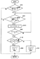
図8を参照して、本実施の形態に係る制御装置であるECU8000で実行されるプログラムの制御構造について説明する。なお、図4に示したフローチャートと同じ処理については同じステップ番号を付してある。それらの処理の内容も同じである。したがって、それらについての詳細な説明はここでは繰り返さない。
With reference to FIG. 8, a control structure of a program executed by
S1000にて、ECU8000は、タイマ(タイマ設定値をTしきい値とする)をスタートさせる。S1100にて、ECU8000は、タイマのカウント時間TがTしきい値未満であるか否かを判断する。タイマのカウント時間TがTしきい値未満であると、すなわち、タイムアップしていないと(S1100にてYES)、処理はS600へ移される。もしそうでないと(S1100にてNO)、処理はS700へ移される。
In S1000,
以上のようにして、ニュートラル制御の復帰から前進クラッチを係合させるための油圧が供給され前進クラッチが係合されるまでの時間をタイマで監視して、ニュートラル制御からの復帰を開始してから予め定められた時間が経過すると、初期状態を経過していると判断して、スリップスタートを許可することができる。そうでない場合には、スリップスタートを禁止して、前進クラッチの係合ショックを抑制するとともに、前進クラッチの耐久性を向上することができる。 As described above, the time from the return of neutral control until the hydraulic pressure for engaging the forward clutch is supplied and the forward clutch is engaged is monitored by the timer, and the return from the neutral control is started. When a predetermined time has elapsed, it is determined that the initial state has elapsed, and slip start can be permitted. Otherwise, slip start is prohibited to suppress the engagement shock of the forward clutch, and the durability of the forward clutch can be improved.
<第3の実施の形態>
以下、本発明の第3の実施の形態について説明する。なお、本実施の形態における制御ブロック等は前述の第1の実施の形態と同じである。したがって、それらについての詳細な説明はここでは繰り返さない。本実施の形態は、前述の第1の実施の形態と一部が異なるプログラムを実行する。
<Third Embodiment>
Hereinafter, a third embodiment of the present invention will be described. Note that the control blocks and the like in this embodiment are the same as those in the first embodiment. Therefore, detailed description thereof will not be repeated here. This embodiment executes a program that is partially different from the first embodiment described above.
図9を参照して、本実施の形態に係る制御装置であるECU8000で実行されるプログラムの制御構造について説明する。なお、図4に示したフローチャートと同じ処理については同じステップ番号を付してある。それらの処理の内容も同じである。したがって、それらについての詳細な説明はここでは繰り返さない。
With reference to FIG. 9, a control structure of a program executed by
S2000にて、ECU8000は、タービン回転数NTを検知する。S2100にて、ECU8000は、タービン回転数NTがNTしきい値よりも高いか否かを判断する。タービン回転数NTがNTしきい値よりもまだ高いと(S2100にてYES)、処理はS600へ移される。もしそうでないと(S2100にてNO)、処理はS700へ移される。
In S2000,
以上のようにして、ニュートラル制御の復帰から前進クラッチを係合させるにしたがって、タービン回転数NTが低下するので、ニュートラル制御からの復帰を開始してからタービン回転数NTの変化を検知してタービン回転数NTがNTしきい値以下になると、初期状態を経過していると判断して、スリップスタートを許可することができる。そうでない場合には、スリップスタートを禁止して、前進クラッチの係合ショックを抑制するとともに、前進クラッチの耐久性を向上することができる。 As described above, since the turbine rotational speed NT decreases as the forward clutch is engaged from the return of the neutral control, the change in the turbine rotational speed NT is detected after the start of the return from the neutral control, and the turbine is detected. When the rotational speed NT is equal to or less than the NT threshold value, it is determined that the initial state has elapsed, and slip start can be permitted. Otherwise, slip start is prohibited to suppress the engagement shock of the forward clutch, and the durability of the forward clutch can be improved.
今回開示された実施の形態はすべての点で例示であって制限的なものではないと考えられるべきである。本発明の範囲は上記した説明ではなくて特許請求の範囲によって示され、特許請求の範囲と均等の意味および範囲内でのすべての変更が含まれることが意図される。 The embodiment disclosed this time should be considered as illustrative in all points and not restrictive. The scope of the present invention is defined by the terms of the claims, rather than the description above, and is intended to include any modifications within the scope and meaning equivalent to the terms of the claims.
1000 エンジン、2000 トランスミッション、3000 プラネタリーギヤユニット、4000 油圧回路、5000 ディファレンシャルギヤ、6000 ドライブシャフト、7000 前輪、8000 ECU。 1000 engine, 2000 transmission, 3000 planetary gear unit, 4000 hydraulic circuit, 5000 differential gear, 6000 drive shaft, 7000 front wheel, 8000 ECU.
Claims (5)
前記自動変速機は、ロックアップクラッチを備えたトルクコンバータと変速機構とから構成され、
前進走行ポジションで前記車両の状態が予め定められた条件を満足して停止した場合に、前記係合要素を解放するように前記変速機構を制御するためのニュートラル制御実行手段と、
前記車両の状態が別途定められた条件を満足した場合に、前記係合要素を係合するように前記変速機構を制御するためのニュートラル制御復帰手段と、
前記ニュートラル制御から復帰させて車両を発進させる際に、前記ロックアップクラッチをスリップ状態にするように、前記ロックアップクラッチを制御するための発進制御手段と、
前記ニュートラル制御からの復帰状態を検知するための検知手段と、
前記ニュートラル制御からの復帰状態に基づいて、前記発進制御手段により前記ロックアップクラッチを制御するか否かを決定するための決定手段とを含み、
前記決定手段は、前記ニュートラル制御からの復帰が初期状態であると、前記発進制御手段による制御を禁止するように決定するための手段を含む、自動変速機の制御装置。 A control device for an automatic transmission having an engagement element that is engaged when a vehicle starts.
The automatic transmission includes a torque converter having a lock-up clutch and a transmission mechanism,
Neutral control execution means for controlling the speed change mechanism so as to release the engagement element when the state of the vehicle at a forward traveling position is stopped while satisfying a predetermined condition;
A neutral control return means for controlling the speed change mechanism to engage the engagement element when the state of the vehicle satisfies a separately defined condition;
Start control means for controlling the lock-up clutch so that the lock-up clutch is brought into a slip state when the vehicle is started after returning from the neutral control;
Detecting means for detecting a return state from the neutral control;
Determining means for determining whether to control the lock-up clutch by the start control means based on a return state from the neutral control,
The control device for an automatic transmission, wherein the determining means includes means for determining that the control by the start control means is prohibited when the return from the neutral control is in an initial state.
Priority Applications (6)
| Application Number | Priority Date | Filing Date | Title |
|---|---|---|---|
| JP2005069616A JP4760065B2 (en) | 2005-03-11 | 2005-03-11 | Control device for automatic transmission |
| US11/661,856 US7769516B2 (en) | 2005-03-11 | 2006-03-09 | Automatic gear control device |
| KR1020077010130A KR100875864B1 (en) | 2005-03-11 | 2006-03-09 | Control device of automatic transmission |
| EP06715686A EP1857715B1 (en) | 2005-03-11 | 2006-03-09 | Automatic gear control device |
| CNB2006800009809A CN100498015C (en) | 2005-03-11 | 2006-03-09 | Automatic gear control device |
| PCT/JP2006/305195 WO2006095920A1 (en) | 2005-03-11 | 2006-03-09 | Automatic gear control device |
Applications Claiming Priority (1)
| Application Number | Priority Date | Filing Date | Title |
|---|---|---|---|
| JP2005069616A JP4760065B2 (en) | 2005-03-11 | 2005-03-11 | Control device for automatic transmission |
Publications (3)
| Publication Number | Publication Date |
|---|---|
| JP2006250287A JP2006250287A (en) | 2006-09-21 |
| JP2006250287A5 JP2006250287A5 (en) | 2007-11-15 |
| JP4760065B2 true JP4760065B2 (en) | 2011-08-31 |
Family
ID=36953500
Family Applications (1)
| Application Number | Title | Priority Date | Filing Date |
|---|---|---|---|
| JP2005069616A Expired - Fee Related JP4760065B2 (en) | 2005-03-11 | 2005-03-11 | Control device for automatic transmission |
Country Status (6)
| Country | Link |
|---|---|
| US (1) | US7769516B2 (en) |
| EP (1) | EP1857715B1 (en) |
| JP (1) | JP4760065B2 (en) |
| KR (1) | KR100875864B1 (en) |
| CN (1) | CN100498015C (en) |
| WO (1) | WO2006095920A1 (en) |
Families Citing this family (27)
| Publication number | Priority date | Publication date | Assignee | Title |
|---|---|---|---|---|
| DE102005027098A1 (en) * | 2005-06-11 | 2006-12-14 | Zf Friedrichshafen Ag | Method for switching an automotive automatic transmission with hydrodynamic torque converter when stopping the vehicle |
| JP4978394B2 (en) | 2007-09-19 | 2012-07-18 | トヨタ自動車株式会社 | VEHICLE CONTROL DEVICE, CONTROL METHOD, PROGRAM FOR MAKING THE METHOD TO COMPUTER COMPUTER, AND RECORDING MEDIUM CONTAINING THE PROGRAM |
| JP4349464B2 (en) * | 2008-03-13 | 2009-10-21 | トヨタ自動車株式会社 | Vehicle drive device |
| JP5012734B2 (en) * | 2008-08-29 | 2012-08-29 | アイシン・エィ・ダブリュ株式会社 | Control device for automatic transmission and control method for automatic transmission |
| JP5261224B2 (en) * | 2009-02-12 | 2013-08-14 | トヨタ自動車株式会社 | Control device for automatic transmission for vehicle |
| US8795135B2 (en) | 2009-09-01 | 2014-08-05 | Ford Global Technologies, Llc | Method for controlling an engine during a restart |
| US8401768B2 (en) | 2009-09-01 | 2013-03-19 | Ford Global Technologies, Llc | System and method for restarting an engine |
| JP5377352B2 (en) * | 2010-02-05 | 2013-12-25 | トヨタ自動車株式会社 | Start control device for vehicle power transmission device |
| JP5464270B2 (en) | 2010-03-31 | 2014-04-09 | アイシン・エィ・ダブリュ株式会社 | Control device for automatic transmission |
| JP5387481B2 (en) * | 2010-03-31 | 2014-01-15 | アイシン・エィ・ダブリュ株式会社 | Control device for automatic transmission |
| US8880310B2 (en) * | 2010-03-31 | 2014-11-04 | Aisin Aw Co., Ltd. | Control device of automatic transmission |
| CN102741595B (en) * | 2010-03-31 | 2015-09-16 | 爱信艾达株式会社 | The control gear of automatic transmission |
| CN101885332B (en) * | 2010-06-22 | 2012-08-29 | 重庆长安汽车股份有限公司 | Brake auxiliary control method of automobile AT transmission |
| JP5593908B2 (en) * | 2010-07-20 | 2014-09-24 | トヨタ自動車株式会社 | Control device for lock-up clutch |
| US9254836B2 (en) * | 2011-07-20 | 2016-02-09 | Toyota Jidosha Kabushiki Kaisha | Vehicle control device |
| CN102635692B (en) * | 2012-01-16 | 2015-05-20 | 浙江吉利汽车研究院有限公司 | Clutch neutral gear stopping device for automobile automatic transmission |
| JP6094192B2 (en) * | 2012-12-11 | 2017-03-15 | 三菱自動車工業株式会社 | Shift device |
| DE102013001019A1 (en) * | 2013-01-22 | 2014-07-24 | GM Global Technology Operations LLC (n. d. Ges. d. Staates Delaware) | Method for triggering alarm signal upon malfunction in operation of motor vehicle, involves using vehicle key or code to start motor vehicle, and checking whether gear shift lever is in neutral position in selective path of switching gate |
| US9482341B2 (en) * | 2013-03-11 | 2016-11-01 | Toyota Jidosha Kabushiki Kaisha | Control device for automatic transmission |
| JP5644922B2 (en) * | 2013-09-19 | 2014-12-24 | トヨタ自動車株式会社 | Start control device for vehicle power transmission device |
| CN106030161B (en) * | 2014-02-28 | 2017-08-25 | 爱信艾达株式会社 | The control device of vehicle driving apparatus |
| US10202120B2 (en) | 2016-06-01 | 2019-02-12 | Ford Global Technologies, Llc | Methods and system for decelerating a vehicle |
| US10011283B2 (en) | 2016-06-28 | 2018-07-03 | Ford Global Technologies, Llc | System and method for driving vehicle accessories |
| US10017182B2 (en) | 2016-06-28 | 2018-07-10 | Ford Global Technologies, Llc | System and method for controlling a torque converter clutch |
| US10322725B2 (en) | 2016-07-14 | 2019-06-18 | Ford Global Technologies, Llc | Powertrain lash management |
| US10295054B2 (en) * | 2016-10-28 | 2019-05-21 | Ford Global Technologies, Llc | Method and control for operating transmission during clutch failure when shifting from gear to neutral |
| KR101809257B1 (en) | 2016-12-12 | 2018-01-18 | 한국지질자원연구원 | Regenerative breaking hybrid transmission using differential-gear and operating method thereof |
Family Cites Families (9)
| Publication number | Priority date | Publication date | Assignee | Title |
|---|---|---|---|---|
| JPH0672661B2 (en) * | 1983-01-27 | 1994-09-14 | マツダ株式会社 | Lockup controller for automatic transmission |
| JPS6155455A (en) * | 1984-08-24 | 1986-03-19 | Toyota Motor Corp | Control method at idle operation time of automatic speed changer for vehicle |
| JPS6283537A (en) * | 1985-10-07 | 1987-04-17 | Toyota Motor Corp | Idle operation control method for automatic transmission for car |
| DE19705956C1 (en) * | 1997-02-17 | 1998-02-19 | Zahnradfabrik Friedrichshafen | Torque converter automatic transmission over-run clutch control e.g. for driving off in motor vehicle |
| JP2000304125A (en) * | 1999-04-16 | 2000-11-02 | Mitsubishi Motors Corp | Control device for automatic transmission |
| US6634988B2 (en) * | 2001-01-23 | 2003-10-21 | General Motors Corporation | Transmission shift control |
| JP2002256921A (en) * | 2001-02-28 | 2002-09-11 | Toyota Motor Corp | Vehicular control device |
| JP3873905B2 (en) * | 2003-02-27 | 2007-01-31 | マツダ株式会社 | Transmission control device |
| JP2005003193A (en) * | 2003-05-16 | 2005-01-06 | Toyota Motor Corp | Controller of lockup clutch for vehicle |
-
2005
- 2005-03-11 JP JP2005069616A patent/JP4760065B2/en not_active Expired - Fee Related
-
2006
- 2006-03-09 US US11/661,856 patent/US7769516B2/en not_active Expired - Fee Related
- 2006-03-09 KR KR1020077010130A patent/KR100875864B1/en not_active IP Right Cessation
- 2006-03-09 WO PCT/JP2006/305195 patent/WO2006095920A1/en active Application Filing
- 2006-03-09 CN CNB2006800009809A patent/CN100498015C/en not_active Expired - Fee Related
- 2006-03-09 EP EP06715686A patent/EP1857715B1/en not_active Expired - Fee Related
Also Published As
| Publication number | Publication date |
|---|---|
| CN100498015C (en) | 2009-06-10 |
| WO2006095920B1 (en) | 2006-11-02 |
| US20080172161A1 (en) | 2008-07-17 |
| CN101040135A (en) | 2007-09-19 |
| EP1857715A4 (en) | 2011-07-13 |
| EP1857715B1 (en) | 2012-11-14 |
| JP2006250287A (en) | 2006-09-21 |
| KR20070064656A (en) | 2007-06-21 |
| US7769516B2 (en) | 2010-08-03 |
| EP1857715A1 (en) | 2007-11-21 |
| KR100875864B1 (en) | 2008-12-26 |
| WO2006095920A1 (en) | 2006-09-14 |
Similar Documents
| Publication | Publication Date | Title |
|---|---|---|
| JP4760065B2 (en) | Control device for automatic transmission | |
| JP4737040B2 (en) | Control device and control method for vehicle equipped with automatic transmission | |
| JP4867240B2 (en) | Control device for automatic transmission | |
| JP2008025709A (en) | Controller for automatic transmission for vehicle | |
| JP2004263733A (en) | Control device for transmission | |
| JP2004169867A (en) | Drive control device for vehicle | |
| JP2006300144A (en) | Controller of automatic transmission | |
| JP2006292136A (en) | Control device for automatic transmission | |
| JP4229155B2 (en) | Control device for automatic transmission | |
| JP4888371B2 (en) | Control device and control method for automatic transmission | |
| JP4525389B2 (en) | Control device for automatic transmission | |
| EP1502804A2 (en) | Shift control apparatus for automatic transmission | |
| JP2007170524A (en) | Line pressure control unit of automatic transmission | |
| JP2009275864A (en) | Control device of vehicle | |
| JP3724337B2 (en) | Shift control device for automatic transmission | |
| JP2007162856A (en) | Control device for automatic transmission | |
| JP2001021029A (en) | Shift control method for vehicular automatic transmission | |
| JP4830718B2 (en) | Control device for automatic transmission | |
| JP4645579B2 (en) | Control device and control method for vehicle equipped with automatic transmission, program and recording medium for realizing the control method | |
| JP4622501B2 (en) | Control device for automatic transmission | |
| JP4696398B2 (en) | Direct transmission clutch control device for automatic transmission | |
| JP5040823B2 (en) | Lock-up clutch control device | |
| JP4924015B2 (en) | Control device for automatic transmission | |
| JP2008008426A (en) | Control device of automatic transmission | |
| JP2004036802A (en) | Control device of transmission system for vehicle |
Legal Events
| Date | Code | Title | Description |
|---|---|---|---|
| A521 | Request for written amendment filed |
Free format text: JAPANESE INTERMEDIATE CODE: A523 Effective date: 20070927 |
|
| A621 | Written request for application examination |
Free format text: JAPANESE INTERMEDIATE CODE: A621 Effective date: 20070927 |
|
| A131 | Notification of reasons for refusal |
Free format text: JAPANESE INTERMEDIATE CODE: A131 Effective date: 20101102 |
|
| A01 | Written decision to grant a patent or to grant a registration (utility model) |
Free format text: JAPANESE INTERMEDIATE CODE: A01 Effective date: 20110510 |
|
| A61 | First payment of annual fees (during grant procedure) |
Free format text: JAPANESE INTERMEDIATE CODE: A61 Effective date: 20110523 |
|
| FPAY | Renewal fee payment (event date is renewal date of database) |
Free format text: PAYMENT UNTIL: 20140617 Year of fee payment: 3 |
|
| FPAY | Renewal fee payment (event date is renewal date of database) |
Free format text: PAYMENT UNTIL: 20140617 Year of fee payment: 3 |
|
| LAPS | Cancellation because of no payment of annual fees |