JP4758367B2 - Air conditioner - Google Patents
Air conditioner Download PDFInfo
- Publication number
- JP4758367B2 JP4758367B2 JP2007032350A JP2007032350A JP4758367B2 JP 4758367 B2 JP4758367 B2 JP 4758367B2 JP 2007032350 A JP2007032350 A JP 2007032350A JP 2007032350 A JP2007032350 A JP 2007032350A JP 4758367 B2 JP4758367 B2 JP 4758367B2
- Authority
- JP
- Japan
- Prior art keywords
- refrigerant
- control valve
- indoor
- indoor unit
- heat exchanger
- Prior art date
- Legal status (The legal status is an assumption and is not a legal conclusion. Google has not performed a legal analysis and makes no representation as to the accuracy of the status listed.)
- Expired - Fee Related
Links
Images


Classifications
-
- F—MECHANICAL ENGINEERING; LIGHTING; HEATING; WEAPONS; BLASTING
- F25—REFRIGERATION OR COOLING; COMBINED HEATING AND REFRIGERATION SYSTEMS; HEAT PUMP SYSTEMS; MANUFACTURE OR STORAGE OF ICE; LIQUEFACTION SOLIDIFICATION OF GASES
- F25B—REFRIGERATION MACHINES, PLANTS OR SYSTEMS; COMBINED HEATING AND REFRIGERATION SYSTEMS; HEAT PUMP SYSTEMS
- F25B13/00—Compression machines, plants or systems, with reversible cycle
-
- F—MECHANICAL ENGINEERING; LIGHTING; HEATING; WEAPONS; BLASTING
- F25—REFRIGERATION OR COOLING; COMBINED HEATING AND REFRIGERATION SYSTEMS; HEAT PUMP SYSTEMS; MANUFACTURE OR STORAGE OF ICE; LIQUEFACTION SOLIDIFICATION OF GASES
- F25B—REFRIGERATION MACHINES, PLANTS OR SYSTEMS; COMBINED HEATING AND REFRIGERATION SYSTEMS; HEAT PUMP SYSTEMS
- F25B2313/00—Compression machines, plants or systems with reversible cycle not otherwise provided for
- F25B2313/023—Compression machines, plants or systems with reversible cycle not otherwise provided for using multiple indoor units
- F25B2313/0233—Compression machines, plants or systems with reversible cycle not otherwise provided for using multiple indoor units in parallel arrangements
-
- F—MECHANICAL ENGINEERING; LIGHTING; HEATING; WEAPONS; BLASTING
- F25—REFRIGERATION OR COOLING; COMBINED HEATING AND REFRIGERATION SYSTEMS; HEAT PUMP SYSTEMS; MANUFACTURE OR STORAGE OF ICE; LIQUEFACTION SOLIDIFICATION OF GASES
- F25B—REFRIGERATION MACHINES, PLANTS OR SYSTEMS; COMBINED HEATING AND REFRIGERATION SYSTEMS; HEAT PUMP SYSTEMS
- F25B2313/00—Compression machines, plants or systems with reversible cycle not otherwise provided for
- F25B2313/031—Sensor arrangements
- F25B2313/0314—Temperature sensors near the indoor heat exchanger
-
- F—MECHANICAL ENGINEERING; LIGHTING; HEATING; WEAPONS; BLASTING
- F25—REFRIGERATION OR COOLING; COMBINED HEATING AND REFRIGERATION SYSTEMS; HEAT PUMP SYSTEMS; MANUFACTURE OR STORAGE OF ICE; LIQUEFACTION SOLIDIFICATION OF GASES
- F25B—REFRIGERATION MACHINES, PLANTS OR SYSTEMS; COMBINED HEATING AND REFRIGERATION SYSTEMS; HEAT PUMP SYSTEMS
- F25B2600/00—Control issues
- F25B2600/25—Control of valves
- F25B2600/2513—Expansion valves
Landscapes
- Engineering & Computer Science (AREA)
- Physics & Mathematics (AREA)
- Mechanical Engineering (AREA)
- Thermal Sciences (AREA)
- General Engineering & Computer Science (AREA)
- Air Conditioning Control Device (AREA)
Description
本発明は,室内空気及び冷媒の間で熱交換を行う室内熱交換器を有する複数の室内ユニットが並列接続された所謂マルチ式の空気調和機に関し,特に,少なくとも一つの室内ユニットで暖房運転が実行されているときに,停止中の他の室内ユニットにおける液体冷媒の貯溜量を適量に制御するための手法に関するものである。 The present invention relates to a so-called multi-type air conditioner in which a plurality of indoor units having indoor heat exchangers for exchanging heat between indoor air and refrigerant are connected in parallel, and in particular, heating operation is performed in at least one indoor unit. The present invention relates to a technique for controlling the amount of liquid refrigerant stored in other indoor units that are stopped to an appropriate amount when being executed.
従来から,室内空気及び冷媒の間で熱交換を行う室内空気熱交換器を有する複数の室内ユニットが,圧縮機や室外空気熱交換器などを有する一つの室外ユニットに並列接続される所謂マルチ式の空気調和機が知られている。以下,図1のブロック図を用いて具体的に説明する。
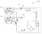
図1に示すように,空気調和機Yは,圧縮機1,四方弁2,室外空気熱交換器3,及び二つの冷媒制御弁41,42を有する室外ユニット10と,室内空気熱交換器21を有する室内ユニット20と,室内空気熱交換器31を有する室内ユニット30と,を備えて構成されている。空気調和機Yでは,圧縮機1,四方弁2,室外空気熱交換器3に,冷媒制御弁41及び室内空気熱交換器21と,冷媒制御弁42及び室内空気熱交換器31とが並列接続されている。ここで,冷媒制御弁41,42は,室外空気熱交換器3と室内空気熱交換器21,31各々との間に配置されており,その室外空気熱交換器3と室内空気熱交換器各々との間の冷媒の流量を制御する制御弁である。
Conventionally, a plurality of indoor units having an indoor air heat exchanger for exchanging heat between indoor air and a refrigerant are connected in parallel to a single outdoor unit having a compressor, an outdoor air heat exchanger, or the like. Air conditioners are known. This will be specifically described below with reference to the block diagram of FIG.
As shown in FIG. 1, the air conditioner Y includes a
このように構成された空気調和機Yでは,例えば室内ユニット20だけで暖房運転を行い,他方の室内ユニット30を停止させる場合,冷媒制御弁41は開かれるが,冷媒制御弁42は閉じられる。しかし,空気調和機Yでは,このような場合にも,停止中の室内ユニット30に圧縮機1からのガス状冷媒が流れ込むことになる。そして,室内ユニット30の室内空気熱交換器31の温度が低下すると,ガス状冷媒が室内ユニット30内で液状化して貯溜する。この停止中の室内ユニット30内の液体冷媒の貯溜量が増えると,暖房運転中の室内ユニット20に十分な冷媒が供給されず,室内ユニット20における暖房性能が低下する。
そのため,従来から,暖房運転中の室内ユニット20の暖房性能の低下を防止するべく,停止中の室内ユニット30に対応する冷媒制御弁42を少し開いておくことにより室内ユニット30に貯溜する冷媒量を適量に維持することが提案されている(例えば,特許文献1参照)。
In the air conditioner Y configured as described above, for example, when the heating operation is performed only by the
Therefore, conventionally, the refrigerant amount stored in the
また,従来から行われている他の手法として,停止中の室内ユニット30内の冷媒の貯溜量に応じて冷媒制御弁42の開閉を切り替えることによって,該室内ユニット30内の冷媒の貯溜量を適量に制御することが知られている。以下,このような手法の一例について具体的に説明する。
図1に示すように,空気調和機Yの室内ユニット20,30には,室内空気熱交換器21,31の冷媒制御弁41,42側の出口の冷媒温度を検出するための出口温度センサ22,32と,室内空気熱交換器21,31内の冷媒温度を検出するための中間温度センサ23,33と,が設けられている。ここで,室内ユニット30の中間温度センサ33と室内ユニット20の出口温度センサ22との温度差を参照すれば,室内ユニット30内の液体冷媒の貯溜量を推測値として検出することが可能である。具体的には,その温度差が小さくなる程,室内ユニット30の液体冷媒の貯溜量が多くなり,温度差が大きくなる程,室内ユニット30内の液体冷媒の貯溜量が少なくなると推測することができる。
空気調和機Yでは,不図示の制御部によって,前記温度差が予め設定された温度差以下となった場合,即ち室内ユニット30の液体冷媒の貯溜量が予め設定された上限値以上となった場合に,冷媒制御弁42が開かれて室内ユニット30に貯溜していた液体冷媒が室外空気熱交換器3に流される。このとき,冷媒制御弁42の開度は,室内ユニット30内の液体冷媒を減少させることができる程度に大きな一定の値に設定されている。
その後,前記温度差が予め設定された温度差よりも大きくなると,即ち室内ユニット30に貯溜していた液体冷媒の量を適量まで減少させることができると,冷媒制御弁42は不図示の制御部によって閉鎖される。
このような従来手法では,停止中の室内ユニット30に貯溜した液体冷媒の量に応じて冷媒制御弁42の開閉動作が繰り返されることによって,停止中の室内ユニット30の液体冷媒の貯溜量が適量に制御され,暖房運転中の室内ユニット20における暖房性能の低下が防止される。
As shown in FIG. 1, the
In the air conditioner Y, when the temperature difference is less than or equal to a preset temperature difference by a control unit (not shown), that is, the storage amount of the liquid refrigerant in the
Thereafter, when the temperature difference becomes larger than a preset temperature difference, that is, when the amount of liquid refrigerant stored in the
In such a conventional technique, the opening / closing operation of the
しかしながら,従来手法では,冷媒制御弁42を開状態と閉状態との間で切り替えるため,開状態のときの開度を,停止中の室内ユニット30内の液体冷媒を減少させることができるように十分に大きく設定しておく必要がある。そのため,閉状態から開状態に移行する際に,室内ユニット30内の液体冷媒が冷媒制御弁42を介して多量に室外ユニット10に流入することになり,圧縮機1などに過負荷がかかって動作が不安定になるという問題がある。
従って,本発明は上記事情に鑑みてなされたものであり,その目的とするところは,少なくとも一つの室内ユニットで暖房運転が実行されているときに,他の停止中の室内ユニットに貯溜する液体冷媒を適量に制御する際,その停止中の室内ユニット内の液体冷媒の急な流出を防止することにより,空気調和機の不安定な動作を防止することのできる空気調和機を提供することにある。
However, in the conventional method, since the
Therefore, the present invention has been made in view of the above circumstances, and the object of the present invention is to store liquid stored in other stopped indoor units when heating operation is being performed in at least one indoor unit. To provide an air conditioner capable of preventing unstable operation of an air conditioner by preventing a sudden outflow of liquid refrigerant in an indoor unit when the refrigerant is controlled to an appropriate amount. is there.
上記目的を達成するために本発明は,冷媒を圧縮する圧縮機と,室外空気及び冷媒の間で熱交換を行う室外空気熱交換器と,前記圧縮機及び前記室外空気熱交換器に並列接続され,室内空気及び冷媒の間で熱交換を行う室内空気熱交換器を有する複数の室内ユニットと,前記室外空気熱交換器及び複数の前記室内空気熱交換器の間に設けられ,該室外空気熱交換器及び該室内空気熱交換器各々の間の冷媒の流量を制御する複数の冷媒制御弁と,を備えてなる空気調和機に適用されるものであって,少なくとも一つの前記室内ユニットで暖房運転が実行されているときに,他の停止中の前記室内ユニットに貯溜している液体冷媒の量を検出し,その検出結果が予め設定された上限値以上となった場合に,停止中の前記室内ユニットに対応する前記冷媒制御弁の開度を徐々に増加させることを特徴とする空気調和機として構成される。さらに,前記室内ユニット各々の前記室内空気熱交換器の内部の冷媒温度を検出する複数の中間温度検出手段と,前記室内空気熱交換器の前記冷媒制御弁側の出口の冷媒温度を検出する複数の出口温度検出手段と,を備えてなり,前記冷媒貯溜量検出手段が,暖房運転中の前記室内ユニットに対応する前記出口温度検出手段による検出温度と,停止中の前記室内ユニットに対応する前記中間温度検出手段による検出温度との温度差に基づいて,停止中の前記室内ユニットに貯溜している液体冷媒の量を検出するものであって,前記弁開度制御手段は,前記冷媒制御弁が確実に開いた状態になると規定された開度よりも多い開度から該冷媒制御弁の開度を徐々に増加させるように構成される。
このように構成された空気調和機では,停止中の前記室内ユニットに貯溜した液体冷媒を徐々に流出させることができるため,多量の液体冷媒が急に前記圧縮機などに流入することがなく,該空気調和機の不安定な動作を防止することができる。なお,前記冷媒制御弁の開度を徐々に増加させる手法としては,予め設定された関数(例えば開度と経過時間との関係)に従って増加させることや,所定時間経過毎に所定量ずつ段階的に増加させることなどが考えられるが,これに限られるものではない。要するに,前記室内ユニットに貯溜した液体冷媒を少しずつ流出させることができる手法であればよい。
To achieve the above object, the present invention provides a compressor for compressing a refrigerant, an outdoor air heat exchanger for exchanging heat between outdoor air and the refrigerant, and a parallel connection to the compressor and the outdoor air heat exchanger. A plurality of indoor units having an indoor air heat exchanger for exchanging heat between indoor air and a refrigerant, and the outdoor air heat exchanger and the plurality of indoor air heat exchangers. And a plurality of refrigerant control valves for controlling the flow rate of refrigerant between each of the heat exchanger and the indoor air heat exchanger, wherein the air conditioner includes at least one indoor unit. When heating operation is being performed, the amount of liquid refrigerant stored in the other indoor units that have been stopped is detected, and if the detection result exceeds the preset upper limit value, Before corresponding to the indoor unit Configured as an air conditioner, wherein the gradually increasing the opening degree of the refrigerant control valve. Further, a plurality of intermediate temperature detecting means for detecting the refrigerant temperature inside the indoor air heat exchanger of each of the indoor units, and a plurality of refrigerant temperatures for detecting the refrigerant temperature at the outlet of the indoor air heat exchanger on the refrigerant control valve side. Outlet temperature detection means, wherein the refrigerant storage amount detection means is a temperature detected by the outlet temperature detection means corresponding to the indoor unit during heating operation and the indoor unit corresponding to the stopped indoor unit. Based on the temperature difference from the temperature detected by the intermediate temperature detecting means, the amount of liquid refrigerant stored in the stopped indoor unit is detected, and the valve opening control means comprises the refrigerant control valve When the valve is reliably opened, the opening degree of the refrigerant control valve is gradually increased from an opening degree larger than a prescribed opening degree.
In the air conditioner configured as described above, since the liquid refrigerant stored in the stopped indoor unit can be gradually discharged, a large amount of liquid refrigerant does not suddenly flow into the compressor, Unstable operation of the air conditioner can be prevented. As a method of gradually increasing the opening degree of the refrigerant control valve, the refrigerant control valve is gradually increased according to a preset function (for example, the relationship between the opening degree and the elapsed time), or stepwise by a predetermined amount every predetermined time. However, it is not limited to this. In short, any technique can be used as long as the liquid refrigerant stored in the indoor unit can be discharged little by little .
ここで,前記冷媒制御弁を徐々に開く本発明では,必要以上に前記冷媒制御弁が開かないように,その開度の上限値を設定しておくことが望ましい。具体的には,前記冷媒制御弁を予め設定された開度に達するまで徐々に増加させることが考えられる。
また,停止中の前記室内ユニットの液体冷媒の貯溜量が予め設定された下限値以下となった場合には,停止中の前記室内ユニットに対応する前記冷媒制御弁を閉鎖すればよい。このような動作を繰り返すことにより,停止中の前記室内ユニット内の液体冷媒の貯溜量を適用に制御することができる。
このとき,前記冷媒制御弁を徐々に閉鎖すれば,前記圧縮機の負荷が急に軽くなることを防止することができ,空気調和機の不安定な動作を防止することができる。なお,前記冷媒制御弁の開度を徐々に減少させる手法としては,予め設定された関数(例えば開度と経過時間との関係)に従って減少させることや,所定時間経過毎に所定量ずつ段階的に減少させることなどが考えられるが,これに限られるものではない。要するに,前記冷媒制御弁を流通する液体冷媒を少しずつ減少させることができる手法であればよい。
Here, in the present invention in which the refrigerant control valve is gradually opened, it is desirable to set an upper limit value of the opening so that the refrigerant control valve does not open more than necessary. Specifically, it is conceivable to gradually increase the refrigerant control valve until a preset opening degree is reached.
Further, when the storage amount of the liquid refrigerant in the stopped indoor unit is equal to or lower than a preset lower limit value, the refrigerant control valve corresponding to the stopped indoor unit may be closed. By repeating such an operation, the storage amount of the liquid refrigerant in the stopped indoor unit can be controlled to be applied.
At this time, if the refrigerant control valve is gradually closed, the load on the compressor can be prevented from being lightened suddenly, and the unstable operation of the air conditioner can be prevented. In addition, as a method of gradually decreasing the opening degree of the refrigerant control valve, the refrigerant control valve may be decreased according to a preset function (for example, the relationship between the opening degree and the elapsed time), or may be stepped by a predetermined amount every predetermined time. However, it is not limited to this. In short, any technique can be used as long as the liquid refrigerant flowing through the refrigerant control valve can be gradually reduced.
ところで,前記冷媒制御弁は,入力されたステップ数に対応して開度を制御することにより冷媒の流量を制御するものであることが考えられる。この場合には,前記冷媒制御弁に入力するステップ数を徐々に増加させることにより該冷媒制御弁の開度を徐々に増加させるように構成すればよい。
ここで,前記冷媒制御弁では,その製品誤差によって入力されたステップ数に対応する開度に差が生じる場合があるため,従来のように,停止中の前記室内ユニット内の液体冷媒を流出させるときの開度を一定値に設定している場合,即ち,一定のステップ数を入力するように設定している場合には,前記冷媒制御弁の製品誤差によって冷媒の流量が異なり,例えば冷媒が流出しない場合や多量の冷媒が急に流出してしまうおそれがあった。
しかしながら,本発明によれば,前記冷媒制御弁が徐々に開かれるように制御されるため,該冷媒制御弁の製品誤差にかかわらず,冷媒制御弁が確実に開かれることになり,しかも多量の冷媒が急に流出することもない。
By the way, it is conceivable that the refrigerant control valve controls the flow rate of the refrigerant by controlling the opening degree corresponding to the input number of steps. In this case, the opening degree of the refrigerant control valve may be gradually increased by gradually increasing the number of steps input to the refrigerant control valve.
Here, in the refrigerant control valve, there may be a difference in the opening corresponding to the number of steps inputted due to the product error, so that the liquid refrigerant in the stopped indoor unit flows out as in the conventional case. When the opening is set to a constant value, that is, when a constant number of steps is input, the flow rate of the refrigerant varies depending on the product error of the refrigerant control valve. There was a possibility that a large amount of refrigerant would suddenly flow out when it did not flow out.
However, according to the present invention, since the refrigerant control valve is controlled to be gradually opened, the refrigerant control valve is surely opened regardless of the product error of the refrigerant control valve, and a large amount of The refrigerant does not flow out suddenly.
また,前記冷媒制御弁に入力するステップ数を0から徐々に増加させていくと,該冷媒制御弁によっては開き始めるまで,即ち液体冷媒が流出し始めるまでに時間がかかるものがある。そこで,前記冷媒制御弁に0よりも大きい所定のステップ数を入力し,その後,前記冷媒制御弁に入力するステップ数を前記所定のステップ数から徐々に増加させることが望ましい。これにより,停止中の前記室内ユニット内に貯溜する液体冷媒量が前記上限値に達してから,該室内ユニット内の液体冷媒の貯溜量を適量に減少させるまでに要する時間を短縮することができる。
具体的には,前記所定のステップ数を,前記冷媒制御弁の製品仕様において該冷媒制御弁が確実に開いた状態になると定められた値以上に設定しておくことが望ましい。これにより,前記冷媒制御弁に製品誤差が生じていても,少なくとも前記冷媒制御弁が確実に開かれた状態から徐々に開き始められるため,停止中の前記室内ユニット内の冷媒の貯溜量を迅速に減少させることができる。
Further, when the number of steps input to the refrigerant control valve is gradually increased from 0, it may take time until the refrigerant control valve starts to open, that is, until the liquid refrigerant starts to flow out. Therefore, it is desirable to input a predetermined number of steps larger than 0 to the refrigerant control valve, and then gradually increase the number of steps input to the refrigerant control valve from the predetermined number of steps. As a result, it is possible to shorten the time required until the amount of liquid refrigerant stored in the indoor unit is reduced to an appropriate amount after the amount of liquid refrigerant stored in the stopped indoor unit reaches the upper limit. .
Specifically, it is desirable that the predetermined number of steps is set to be equal to or greater than a value that is determined in the product specification of the refrigerant control valve so that the refrigerant control valve is surely opened. As a result, even if a product error occurs in the refrigerant control valve, at least the refrigerant control valve can be gradually opened from the reliably opened state, so that the refrigerant storage amount in the stopped indoor unit can be quickly increased. Can be reduced.
本発明によれば,停止中の前記室内ユニットに貯溜した液体冷媒を徐々に流出させることができるため,多量の液体冷媒が急に前記圧縮機などに流入することがなく,該空気調和機の不安定な動作を防止することができる。
また,前記冷媒制御弁が,入力されたステップ数に対応して開度を制御することにより冷媒の流量を制御するものである場合には,前記冷媒制御弁に0よりも大きい所定のステップ数を入力し,その後,前記冷媒制御弁に入力するステップ数を前記所定のステップ数から徐々に増加させることにより,停止中の前記室内ユニット内に貯溜する液体冷媒量が前記上限値に達してから,該室内ユニット内の液体冷媒の貯溜量を適量に減少させるまでに要する時間を短縮することができる。
According to the present invention, since the liquid refrigerant stored in the stopped indoor unit can be gradually discharged, a large amount of liquid refrigerant does not suddenly flow into the compressor or the like. Unstable operation can be prevented.
In addition, when the refrigerant control valve controls the flow rate of the refrigerant by controlling the opening degree in accordance with the input number of steps, the refrigerant control valve has a predetermined number of steps greater than zero. And then the number of steps input to the refrigerant control valve is gradually increased from the predetermined number of steps until the amount of liquid refrigerant stored in the stopped indoor unit reaches the upper limit value. Thus, the time required to reduce the storage amount of the liquid refrigerant in the indoor unit to an appropriate amount can be shortened.
以下添付図面を参照しながら,本発明の実施の形態について説明し,本発明の理解に供する。尚,以下の実施の形態は,本発明を具体化した一例であって,本発明の技術的範囲を限定する性格のものではない。
ここに,図1は本発明の実施の形態に係る空気調和機Xの概略構成を示すブロック図,図2は本発明の実施の形態に係る空気調和機Xの制御回路の概略構成を示すブロック図,図3は冷媒制御弁41,42の動作特性の誤差を説明するための図,図4は本発明の実施の形態に係る空気調和機Xにおいて実行される弁開度制御処理の手順の一例を説明するためのフローチャート,図5は弁開度制御処理による制御動作を説明するための図である。
まず,図1〜図3を用いて,本発明の実施の形態に係る空気調和機Xの概略構成について説明する。
図1に示すように,空気調和機Xは,冷媒を圧縮する圧縮機1,冷媒の流通方向を切り替える四方弁2,室外空気と冷媒との間で熱交換を行う室外空気熱交換器3,冷媒の流量を制御する二つの冷媒制御弁41,42などを有する室外ユニット10と,圧縮機1及び室外空気熱交換器3に並列接続され,室内空気及び冷媒の間で熱交換を行う室内空気熱交換器21,31を有する室内ユニット20及び30と,を備えて概略構成されている。なお,冷媒制御弁41,42は,室内ユニット20,30側に設けられていてもかまわない。また,空気調和機Xは,一般的なマルチ式の空気調和機が備える室外送風ファンや室内送風ファンなどの他の構成要素も備えているがここでは説明を省略する。
空気調和機Xでは,圧縮機1から吐出される冷媒が,図示する実線矢印方向又は破線矢印方向に流通されて室内空気熱交換器21,31に流入されることによって,室内ユニット20,30において暖房運転(実線)又は冷房運転(破線)が実現される。
Hereinafter, embodiments of the present invention will be described with reference to the accompanying drawings so that the present invention can be understood. The following embodiment is an example embodying the present invention, and does not limit the technical scope of the present invention.
FIG. 1 is a block diagram showing a schematic configuration of the air conditioner X according to the embodiment of the present invention. FIG. 2 is a block diagram showing a schematic configuration of a control circuit of the air conditioner X according to the embodiment of the present invention. FIG. 3 is a diagram for explaining an error in operating characteristics of the
First, the schematic configuration of the air conditioner X according to the embodiment of the present invention will be described with reference to FIGS.
As shown in FIG. 1, an air conditioner X includes a
In the air conditioner X, the refrigerant discharged from the
冷媒制御弁41,42は,室外ユニット10の室外空気熱交換器3と,室内ユニット20,30の室内空気熱交換器21,31との間にそれぞれ配置されており,室外空気熱交換器3と室内空気熱交換器21,31各々との間の冷媒の流量を制御する制御弁であって,その開度は後述の制御部5(図2参照)によって制御される。
具体的に,冷媒制御弁41,42は,入力されたステップ数に対応して回転するステッピングモータと,該ステッピングモータの回転に伴って開閉する弁とを有しており,入力されたステップ数に対応して弁の開度を制御するものである。このように構成された冷媒制御弁41,42には,製品によって動作特性に誤差が生じる場合がある。ここに,図2は,冷媒制御弁の動作特性の誤差を説明するための図である。図2に示すように,冷媒制御弁41や42に用いられる冷媒制御弁では,同じステップR1〜R5が入力された場合であっても,そのときの開度,即ち冷媒の流量が製品によって異なる(図2の動作特性A〜C)。但し,このような冷媒制御弁には,その製品仕様において,該冷媒制御弁が確実に開いた状態となるときのステップ数が規定されている。本実施の形態では,冷媒制御弁41,42に用いられる冷媒制御弁が確実に開いた状態となるときのステップ数が,図2に示すステップR3(ステップ数50)であると規定されているものとする。
The
Specifically, the
また,図1に示すように,室内ユニット20には,室内空気熱交換器21の冷媒制御弁41側の出口の冷媒温度を検出するサーミスタ等の出口温度センサ22(出口温度検出手段の一例)と,室内空気熱交換器21の内部の冷媒温度を検出するサーミスタ等の中間温度センサ23(中間温度検出手段の一例)と,室内空気熱交換器21の圧縮機1側の出口の冷媒温度を検出するサーミスタ等の出口温度センサ24とが設けられている。
同様に,室内ユニット30には,室内空気熱交換器31の冷媒制御弁42側の出口の冷媒温度を検出するサーミスタ等の出口温度センサ32(出口温度検出手段の一例)と,室内空気熱交換器31の内部の冷媒温度を検出するサーミスタ等の中間温度センサ33(中間温度検出手段の一例)と,室内空気熱交換器31の圧縮機1側の出口の冷媒温度を検出するサーミスタ等の出口温度センサ34とが設けられている。
As shown in FIG. 1, the
Similarly, the
ここに,図3は,空気調和機Xの制御回路の概略構成を示すブロック図である。
図3に示すように,室外ユニット10には,CPUやRAM,ROM等を有してなり当該室外ユニット10を統括的に制御する制御部5が設けられている。また,室内ユニット20,30には,CPUやRAM,ROM等を有してなり当該室内ユニット20,30を統括的に制御する制御部25,35が設けられている。制御部5と制御部20,30とは通信可能に接続されている。具体的に,室内ユニット20,30に設けられた出口温度センサ22,24及び中間温度センサ23や,出口温度センサ32,34及び中間温度センサ33の検出温度は,室内ユニット20,30の制御部25,35を介して室外ユニット10の制御部5に入力される。
室外ユニット10の制御部5は,出口温度センサ22,24及び中間温度センサ23や,出口温度センサ32,34及び中間温度センサ33の検出温度に基づいて,圧縮機1や冷媒制御弁41,42,不図示の送風ファンなどを制御する。これにより,例えば冷暖房時における室内空気熱交換器21,31の熱交換性能,即ち室内ユニット20,30による冷暖房時の温度調節が行われる。なお,空気調和機Xの冷房運転や暖房運転などの基本的な制御動作については従来装置と異なるところがないため,ここではその詳細な説明を省略する。
本発明の実施の形態に係る空気調和機Xは,室内ユニット20,30のいずれか一方の室内ユニットで暖房運転が実行され,他方の室内ユニットが停止されている場合に,暖房運転中の室内ユニットの暖房性能の低下を防止するべく,停止中の室内ユニット内に貯溜する冷媒量を適量に制御するための手法に特徴を有しており,以下,この点について詳説する。具体的に,空気調和機Xでは,室外ユニット10の制御部5によって,停止中の室内ユニット内の液体冷媒の貯溜量を適量に制御するための弁開度制御処理(図4のフローチャート参照)が実行される。
FIG. 3 is a block diagram showing a schematic configuration of the control circuit of the air conditioner X.
As shown in FIG. 3, the
The
In the air conditioner X according to the embodiment of the present invention, the heating operation is executed in one of the
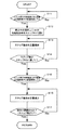
以下,図4のフローチャートに従って,図5を参照しつつ,本発明の実施の形態に係る空気調和機Xにおいて,室外ユニット10の制御部5によって実行される弁開度制御処理の手順の一例について説明する。なお,図中のS11,S12,…は処理手順(ステップ)の番号を表している。
当該弁開度制御処理は,室内ユニット20,30のいずれか一方の室内ユニットで暖房運転が行われており,他方の室内ユニットが停止中である場合に,制御部5によって実行される。ここでは,室内ユニット20で暖房運転が実行され,室内ユニット30が停止中である場合を例に挙げて説明する。なお,室外ユニット10に更に複数の室内ユニットが接続されている場合にも同様に適用することが可能である。
Hereinafter, referring to FIG. 5 according to the flowchart of FIG. 4, in the air conditioner X according to the embodiment of the present invention, an example of the procedure of the valve opening degree control process executed by the
The valve opening control process is executed by the
図4に示すように,まず,ステップS11では,制御部5によって,室内ユニット20の出口温度センサ22により検出されている温度(出口温度)と,室内ユニット30の中間温度センサ33により検出されている温度(中間温度)との温度差が,予め設定された下限温度差以内であるか否かが判断される。前述したように,室内ユニット20,30間の出口温度と中間温度との温度差を参照すれば,停止中の室内ユニット30内の液体冷媒の貯溜量を推測することができる。
ここでは,中間温度センサ33と出口温度センサ22との間の温度差に基づいて,停止中の室内ユニット30内に貯溜している液体冷媒の量を推測値として検出し,その検出量が,予め設定された上限値以上であるか否かを判断している。ここに,室内ユニット20で暖房運転が実行されているときに,停止中の室内ユニット30内の液体冷媒の貯溜量を検出するための処理を実行するときの制御部5が冷媒貯溜量検出手段に相当する。なお,このような手法に限られず,他の手法を用いて室内ユニット30内に貯溜している液体冷媒の量を検出してもかまわない。例えば,室内ユニット30内の冷媒の圧力を検出すれば,室内ユニット30の出口温度センサ32と中間温度センサ33との温度差によって,該室内ユニット30内の液体冷媒の貯溜量を検出することが可能である。
ステップS11において,前記温度差が前記下限温度差以内ではないと判断されている間は(S11のNo側),このステップS11の判断処理が繰り返して実行されるが,前記温度差が前記下限温度差以内であると判断された場合(S11のYes側),即ち室内ユニット30内の液体冷媒の貯溜量が上限値以上となった場合には,処理はステップS12に移行する。なお,前記上限値は,暖房運転中の室内ユニット20に必要な冷媒量に応じて適宜変更することが考えられ,この場合には,前記上限値に対応する前記下限温度差を変更すればよい。
As shown in FIG. 4, first, in step S <b> 11, the
Here, based on the temperature difference between the
While it is determined in step S11 that the temperature difference is not within the lower limit temperature difference (No side of S11), the determination process in step S11 is repeatedly performed. If it is determined that the difference is within the difference (Yes side of S11), that is, if the storage amount of the liquid refrigerant in the
ステップS12では,制御部5によって,室内ユニット30に対応する冷媒制御弁42に,ステップR4(ステップ数60,所定のステップ数の一例)が入力される(図5の時間t1)。ここに,ステップR4は,図2に示したように,冷媒制御弁42が確実に開いた状態となるステップR3(ステップ数50)よりも若干多い値に設定されたものである。したがって,冷媒制御弁42は,ステップS12において確実に開いた状態になり,停止中の室内ユニット30内に貯溜された液体冷媒が,冷媒制御弁42を介して流出し始める。
このとき,空気調和機Xでは,後述するステップS13〜S14において,冷媒制御弁42が徐々に開かれることになるため,ステップS12における冷媒制御弁42の開度の初期値を,空気調和機Xの動作が不安定とならないような小さな値に設定することができる。
また,冷媒制御弁42の開度の初期値が,ステップR3よりも若干多いステップR4に設定されているため,入力されたステップ数と実際の開度とが,該冷媒制御弁42の製品誤差によって異なる場合(図2参照)であっても,確実に液体冷媒が流通する状態に移行させることができる。したがって,停止中の室内ユニット30内に貯溜する液体冷媒量が前記上限値に達してから,該室内ユニット30内の液体冷媒の貯溜量を適量に減少させるまでに要する時間を短縮することができる。なお,ステップR4に代えて,ステップR3やそれ以下のステップ数を初期値に設定することも他の実施例として考えられる。要するに,0よりも大きく,且つ空気調和機Xの動作が不安定にならない程度のステップ数を初期値として設定しておけばよい。
In step S12, the
At this time, in the air conditioner X, the
In addition, since the initial value of the opening degree of the
その後ステップS13〜S14では,制御部5によって,冷媒制御弁42に入力するステップ数が,予め設定された開度に対応するステップR5(上限値の一例)に達するまでステップR4から徐々に増加される(図5に示す時間t1‐t2間)。ここに,かかる処理を実行するときの制御部5が弁開度制御手段に相当する。具体的には,図5に示すように,冷媒制御弁42のステップ数(開度)と時間との比例関数に従ってリニアに増加される。また,冷媒制御弁42の開度を徐々に増加させる手法としては,他に,所定時間経過毎に1ステップずつ(所定量ずつ)段階的に増加させることなども考えられ,これに限られるものではない。即ち,室内ユニット30内に貯溜した液体冷媒を少しずつ流出させることのできる手法であればよい。これにより,多量の液体冷媒が急に圧縮機1などに流入することがなく,該空気調和機Xの不安定な動作を防止することができる。
ここで,ステップR5は,室内ユニット30内の液体冷媒を減少させることができる程度に大きなものであって,例えば従来の開状態の開度に対応するステップ数として用いられていたものである。
具体的には,ステップS14で,冷媒制御弁42に入力しているステップ数がステップR5に達したと判断されるまでの間(S14のNo側),ステップS13では,冷媒制御弁42に入力するステップ数が所定量づつ増加される。
そして,ステップS14において冷媒制御弁42に入力するステップ数がステップR5に達したと判断された場合(S14のYes側),即ち,冷媒制御弁42の開度がステップR5に対応する開度に達した場合,処理はステップS15に移行する。このとき,冷媒制御弁42は,ステップR5に対応する開度で開いた状態で維持される。
Thereafter, in steps S13 to S14, the number of steps input to the
Here, step R5 is large enough to reduce the liquid refrigerant in the
Specifically, until it is determined in step S14 that the number of steps input to the
When it is determined in step S14 that the number of steps input to the
ステップS15では,制御部5によって,室内ユニット20の出口温度センサ22により検出されている温度(出口温度)と,室内ユニット30の出口温度センサ33により検出されている温度(中間温度)との温度差が,予め設定された上限温度差以上であるか否かが判断される。ここでは,中間温度センサ33と出口温度センサ22との間の温度差に基づいて,停止中の室内ユニット30内に貯溜している液体冷媒の量を推測値として検出し,その検出量が,予め設定された下限値以下であるか否かを判断している。なお,前記下限温度差及び前記上限温度差に差を設けておくことで冷媒制御弁42の開閉のハンチング動作を少なくすることができる。
ここで,前記温度差が前記上限温度差以上ではないと判断されている間は(S15のNo側,図5に示す時間t2‐t3間),ステップS15の判断処理が繰り返して実行されるが,前記温度差が前記上限温度差以上であると判断された場合(S15のYes側),即ち室内ユニット30内の液体冷媒の貯溜量が下限値以下となった場合には,処理はステップS16に移行する。
In step S15, the temperature between the temperature detected by the
Here, while it is determined that the temperature difference is not greater than or equal to the upper limit temperature difference (No side of S15, between time t2 and t3 shown in FIG. 5), the determination process of step S15 is repeatedly executed. When it is determined that the temperature difference is greater than or equal to the upper limit temperature difference (Yes in S15), that is, when the storage amount of the liquid refrigerant in the
その後,ステップS16〜S17では,制御部5によって,冷媒制御弁42に入力するステップ数が,0になるまで,即ち冷媒制御弁42が完全に閉鎖されるまで,ステップR5から徐々に減少される(図5に示す時間t3‐t4間)。
具体的には,ステップS17で,冷媒制御弁42に入力しているステップ数が0に達したと判断されるまでの間(S17のNo側),ステップS16では,冷媒制御弁42に入力するステップ数が所定量づつ減少される。例えば,1分間経過するごとにステップR4,R3,R2,R1,0の順に変更して閉鎖することが考えられる。これにより,冷媒制御弁42は,ステップR5に対応する開度から完全に閉鎖される状態まで徐々に閉じられることになる。なお,冷媒制御弁42の開度を徐々に閉鎖するための手法としては,前記したように所定時間経過毎に段階的に減少させることの他に,例えば図5に破線で示すように冷媒制御弁42のステップ数(開度)と時間との比例関数に従ってリニアに減少させることなども考えられ,これに限られるものではない。即ち,冷媒制御弁42を流通する液体冷媒を少しずつ減少させることのできる手法であればよい。
このように,空気調和機Xでは,冷媒制御弁42が,ステップR5に対応する開度から全閉状態まで徐々に閉じられるため,冷媒制御弁42が急に閉じられて圧縮機1への負荷が急に軽くなることを防止することができ,空気調和機Xの動作が不安定になることを防止することができる。
Thereafter, in steps S16 to S17, the number of steps input to the
Specifically, until it is determined in step S17 that the number of steps input to the
Thus, in the air conditioner X, since the
1…圧縮機
2…四方弁
3…室外空気熱交換器
41,42…冷媒制御弁
5…制御部
10…室外ユニット
20,30…室内ユニット
21,31…室内空気熱交換器
22,32…出口温度センサ(出口温度検出手段の一例)
23,33…中間温度センサ(中間温度検出手段の一例)
24,34…出口温度センサ
25,35…制御部
DESCRIPTION OF
23, 33 ... Intermediate temperature sensor (an example of intermediate temperature detection means)
24, 34 ...
Claims (3)
少なくとも一つの前記室内ユニットで暖房運転が実行されているときに,他の停止中の前記室内ユニットに貯溜している液体冷媒の量を検出する冷媒貯溜量検出手段と,
前記冷媒貯溜量検出手段による検出結果が予め設定された上限値以上となった場合に,停止中の前記室内ユニットに対応する前記冷媒制御弁の開度を徐々に増加させる弁開度制御手段と,
前記室内ユニット各々の前記室内空気熱交換器の内部の冷媒温度を検出する複数の中間温度検出手段と,
前記室内空気熱交換器の前記冷媒制御弁側の出口の冷媒温度を検出する複数の出口温度検出手段と,
を備えてなり,
前記冷媒貯溜量検出手段が,暖房運転中の前記室内ユニットに対応する前記出口温度検出手段による検出温度と,停止中の前記室内ユニットに対応する前記中間温度検出手段による検出温度との温度差に基づいて,停止中の前記室内ユニットに貯溜している液体冷媒の量を検出するものであって,
前記弁開度制御手段は,前記冷媒制御弁が確実に開いた状態になると規定された開度よりも多い開度から該冷媒制御弁の開度を徐々に増加させることを特徴とする空気調和機。 A compressor that compresses the refrigerant, an outdoor air heat exchanger that exchanges heat between the outdoor air and the refrigerant, and a heat exchange between the indoor air and the refrigerant that are connected in parallel to the compressor and the outdoor air heat exchanger. A plurality of indoor units having an indoor air heat exchanger, and the outdoor air heat exchanger and the plurality of indoor air heat exchangers, each of the outdoor air heat exchanger and the indoor air heat exchanger. An air conditioner comprising a plurality of refrigerant control valves for controlling the flow rate of refrigerant between
Refrigerant storage amount detection means for detecting the amount of liquid refrigerant stored in the other stopped indoor units when the heating operation is executed in at least one of the indoor units;
Valve opening control means for gradually increasing the opening degree of the refrigerant control valve corresponding to the stopped indoor unit when the detection result by the refrigerant storage amount detection means exceeds a preset upper limit value; ,
A plurality of intermediate temperature detecting means for detecting a refrigerant temperature inside the indoor air heat exchanger of each of the indoor units;
A plurality of outlet temperature detecting means for detecting a refrigerant temperature at an outlet on the refrigerant control valve side of the indoor air heat exchanger;
Ri name with a,
The refrigerant storage amount detecting means detects a temperature difference between a temperature detected by the outlet temperature detecting means corresponding to the indoor unit being heated and a temperature detected by the intermediate temperature detecting means corresponding to the stopped indoor unit. And detecting the amount of liquid refrigerant stored in the stopped indoor unit,
The valve opening control means gradually increases the opening of the refrigerant control valve from an opening larger than a predetermined opening when the refrigerant control valve is surely opened. Machine.
前記弁開度制御手段が,前記冷媒制御弁に入力するステップ数を徐々に増加させるものである請求項1又は2のいずれかに記載の空気調和機。 The refrigerant control valve controls the flow rate of the refrigerant by controlling the opening degree corresponding to the input number of steps,
The air conditioner according to any one of claims 1 and 2, wherein the valve opening control means gradually increases the number of steps input to the refrigerant control valve .
Priority Applications (1)
| Application Number | Priority Date | Filing Date | Title |
|---|---|---|---|
| JP2007032350A JP4758367B2 (en) | 2007-02-13 | 2007-02-13 | Air conditioner |
Applications Claiming Priority (1)
| Application Number | Priority Date | Filing Date | Title |
|---|---|---|---|
| JP2007032350A JP4758367B2 (en) | 2007-02-13 | 2007-02-13 | Air conditioner |
Publications (3)
| Publication Number | Publication Date |
|---|---|
| JP2008196775A JP2008196775A (en) | 2008-08-28 |
| JP2008196775A5 JP2008196775A5 (en) | 2009-05-21 |
| JP4758367B2 true JP4758367B2 (en) | 2011-08-24 |
Family
ID=39755881
Family Applications (1)
| Application Number | Title | Priority Date | Filing Date |
|---|---|---|---|
| JP2007032350A Expired - Fee Related JP4758367B2 (en) | 2007-02-13 | 2007-02-13 | Air conditioner |
Country Status (1)
| Country | Link |
|---|---|
| JP (1) | JP4758367B2 (en) |
Families Citing this family (6)
| Publication number | Priority date | Publication date | Assignee | Title |
|---|---|---|---|---|
| KR101951673B1 (en) * | 2011-12-12 | 2019-04-25 | 엘지전자 주식회사 | Multi type Air Conditioner and Method for preventing the refrigerant's remnants for the same |
| WO2017026025A1 (en) * | 2015-08-10 | 2017-02-16 | 三菱電機株式会社 | Multiple-type air conditioner |
| JP2019045056A (en) * | 2017-08-31 | 2019-03-22 | ダイキン工業株式会社 | Refrigeration system |
| JP2019086251A (en) * | 2017-11-09 | 2019-06-06 | 三菱重工サーマルシステムズ株式会社 | Control device of multi-type air conditioning device, multi-type air conditioning device, control method of multi-type air conditioning device, and control program of multi-type air conditioning device |
| JP7147279B2 (en) * | 2018-06-08 | 2022-10-05 | 株式会社デンソー | Vehicle refrigeration cycle equipment |
| JP7487698B2 (en) * | 2021-03-31 | 2024-05-21 | 株式会社デンソー | Refrigeration Cycle Equipment |
Family Cites Families (6)
| Publication number | Priority date | Publication date | Assignee | Title |
|---|---|---|---|---|
| JPH0784954B2 (en) * | 1988-12-12 | 1995-09-13 | ダイキン工業株式会社 | Refrigerant retention device for air conditioner |
| JP2502831B2 (en) * | 1991-03-27 | 1996-05-29 | 松下電器産業株式会社 | Multi-room air conditioner |
| JPH04198672A (en) * | 1990-11-28 | 1992-07-20 | Matsushita Seiko Co Ltd | Electric expansion valve controller for multi-chamber type air-conditioning machine |
| JP3181117B2 (en) * | 1992-11-30 | 2001-07-03 | 東芝キヤリア株式会社 | Air conditioner |
| JP3097468B2 (en) * | 1994-10-31 | 2000-10-10 | ダイキン工業株式会社 | Control device for air conditioner |
| JP3736969B2 (en) * | 1998-05-20 | 2006-01-18 | 三菱電機株式会社 | Air conditioner |
-
2007
- 2007-02-13 JP JP2007032350A patent/JP4758367B2/en not_active Expired - Fee Related
Also Published As
| Publication number | Publication date |
|---|---|
| JP2008196775A (en) | 2008-08-28 |
Similar Documents
| Publication | Publication Date | Title |
|---|---|---|
| JP4758367B2 (en) | Air conditioner | |
| JP6338761B2 (en) | Air conditioning system | |
| US8215122B2 (en) | Air conditioner and method of controlling the same | |
| CN101611277B (en) | Free-cooling limitation control for air conditioning systems | |
| KR20030097179A (en) | Heat-Pump Air Conditioner's Operating Method | |
| CA2812782C (en) | Expansion valve control system and method for air conditioning apparatus | |
| EP2102571B1 (en) | Free-cooling capacity control for air conditioning systems | |
| CN101270905B (en) | Simultaneous heating and cooling multi-air conditioner and control method thereof | |
| US8205463B2 (en) | Air conditioner and method of controlling the same | |
| CN113405155A (en) | Expansion valve control method and device and multi-connected air conditioner | |
| US11598549B2 (en) | Thermal cycling system and control method of the thermal cycling system | |
| EP1643193B1 (en) | Method of determining the configuration of an air conditioning system | |
| CN112178976B (en) | Heat exchange unit, heat exchange system and method for determining control valve failure therein | |
| JPH09178247A (en) | Control device for multi-room air conditioner | |
| KR102383479B1 (en) | Air conditioner of vehicle with improved performance in low temperature region and controlling method for air conditioner of vehicle in low temperature region | |
| KR100840940B1 (en) | HVAC system and control method | |
| KR20080065196A (en) | How to control overload operation of the air conditioner | |
| JP5216813B2 (en) | Control method for air conditioning system | |
| JP2011094932A (en) | Air-conditioning hot water supply system | |
| KR100680618B1 (en) | Air conditioner and its starting method | |
| JP7533557B2 (en) | Air Conditioning Equipment | |
| CN114537075B (en) | Temperature regulation system, temperature regulation method and storage medium | |
| JPH05133618A (en) | Air conditioner | |
| JPS6217553A (en) | Room temperature control device for air-conditioning device | |
| JPWO2022145004A5 (en) | air conditioner |
Legal Events
| Date | Code | Title | Description |
|---|---|---|---|
| A521 | Request for written amendment filed |
Free format text: JAPANESE INTERMEDIATE CODE: A523 Effective date: 20090327 |
|
| A621 | Written request for application examination |
Free format text: JAPANESE INTERMEDIATE CODE: A621 Effective date: 20090327 |
|
| A977 | Report on retrieval |
Free format text: JAPANESE INTERMEDIATE CODE: A971007 Effective date: 20110125 |
|
| A131 | Notification of reasons for refusal |
Free format text: JAPANESE INTERMEDIATE CODE: A131 Effective date: 20110201 |
|
| A521 | Request for written amendment filed |
Free format text: JAPANESE INTERMEDIATE CODE: A821 Effective date: 20110314 |
|
| RD02 | Notification of acceptance of power of attorney |
Free format text: JAPANESE INTERMEDIATE CODE: A7422 Effective date: 20110314 |
|
| A521 | Request for written amendment filed |
Free format text: JAPANESE INTERMEDIATE CODE: A523 Effective date: 20110315 |
|
| RD04 | Notification of resignation of power of attorney |
Free format text: JAPANESE INTERMEDIATE CODE: A7424 Effective date: 20110315 |
|
| TRDD | Decision of grant or rejection written | ||
| A01 | Written decision to grant a patent or to grant a registration (utility model) |
Free format text: JAPANESE INTERMEDIATE CODE: A01 Effective date: 20110510 |
|
| A61 | First payment of annual fees (during grant procedure) |
Free format text: JAPANESE INTERMEDIATE CODE: A61 Effective date: 20110602 |
|
| R150 | Certificate of patent or registration of utility model |
Ref document number: 4758367 Country of ref document: JP Free format text: JAPANESE INTERMEDIATE CODE: R150 Free format text: JAPANESE INTERMEDIATE CODE: R150 |
|
| FPAY | Renewal fee payment (event date is renewal date of database) |
Free format text: PAYMENT UNTIL: 20140610 Year of fee payment: 3 |
|
| LAPS | Cancellation because of no payment of annual fees |