JP4753279B2 - A plate reel seat and a fishing rod equipped with the plate reel seat - Google Patents
A plate reel seat and a fishing rod equipped with the plate reel seat Download PDFInfo
- Publication number
- JP4753279B2 JP4753279B2 JP2004339076A JP2004339076A JP4753279B2 JP 4753279 B2 JP4753279 B2 JP 4753279B2 JP 2004339076 A JP2004339076 A JP 2004339076A JP 2004339076 A JP2004339076 A JP 2004339076A JP 4753279 B2 JP4753279 B2 JP 4753279B2
- Authority
- JP
- Japan
- Prior art keywords
- plate
- heel
- reel
- reel seat
- mounting
- Prior art date
- Legal status (The legal status is an assumption and is not a legal conclusion. Google has not performed a legal analysis and makes no representation as to the accuracy of the status listed.)
- Expired - Fee Related
Links
Images


Description
本発明は、竿外周面の所定箇所に載置される脚部を有し、その脚部に取付固定用の糸を巻回されて前記竿外周面に固定される板状リールシート及びその板状リールシートを装備した釣り竿に関する。 The present invention includes a plate-shaped reel sheet having a leg portion placed at a predetermined position on the outer peripheral surface of the heel, wound around a fixing thread on the leg portion, and fixed to the outer peripheral surface of the heel, and the plate This relates to a fishing rod equipped with a reel seat .
この種の板状リールシートにおいては、仕掛けを投入するなど、竿を振り出す際に竿に取り付けられた脚部とその脚部を載置支持している竿の外周面との取付部位から異音が発生することがあり、釣り人に不快感を与えていた。
従来、僅かに、板状リールシートを元竿に対して強固に固定すべく、引き揃え強化繊維に熱硬化性樹脂を含浸させたテープで巻き占める構成を採っているものや(特許文献1)や、リール脚をガタツキなく取り付けるために、可動フード内に弾性材を装着するものがあった(特許文献2)。
In this type of plate-shaped reel sheet , such as when a device is inserted, the leg portion attached to the heel when the heel is swung out differs from the attachment site between the outer peripheral surface of the heel on which the leg is placed and supported. A sound may be generated, causing discomfort to the angler.
Conventionally, in order to firmly fix the plate- shaped reel sheet to the main shaft, a configuration in which the reinforced fibers are wound with a tape impregnated with a thermosetting resin is employed (Patent Document 1). In addition, in order to attach the reel leg without rattling, there is one in which an elastic material is mounted in the movable hood (Patent Document 2).
しかし、上記した特許文献に開示された発明は、いずれも、板状リールシートが発する異音を抑制するものではなく、他の目的のためのものであり、この異音の発生を阻止する技術は存在しなかった。 However, the inventions disclosed in the above-mentioned patent documents are not for suppressing the abnormal noise generated by the plate-shaped reel sheet, but for other purposes, and the technology for preventing the generation of this abnormal noise. Did not exist.
本発明の目的は、効果的に板状リールシートからの異音の発生を抑制できる板状リールシート、及びその板状リールシートを取り付けた釣り竿を提供する点にある。 An object of the present invention is to provide a plate-like reel sheet that can effectively suppress the occurrence of abnormal noise from the plate-like reel sheet , and a fishing rod to which the plate-like reel sheet is attached.
〔構成〕
請求項1に係る発明の特徴構成は、前記装着部を、リール脚を挿入保持するフードを取り付けているベースフレームにおける竿先端部、竿尻端部、及び、それらの間に位置する中間部とに設け、前記竿先端部、前記竿尻端部、及び、前記中間部における、夫々の左右端縁に、その端縁の部分を切り離すように、左右端縁から互いに相手側の端縁に向けて入り込む複数の切り込み溝を形成してある点にあり、その作用効果は次の通りである。
〔Constitution〕
The characteristic configuration of the invention according to
〔作用効果〕
異音の発生場所が装着部の釣竿への取付面と釣竿の装着箇所の表面との僅かなスベリ現象に関係していることを突き止めた。そして、このスベリ現象が発生する原因が装着部の変形度合いが小さく、装着部の取付面が竿の外周面に密着し難い点にあることもわかった。これに対して、装着部の周縁部に内側に切り込む切り込み溝を設けた。
このことによって、装着部の周縁部に切り込み溝を形成しない場合に比べて、装着部が変形しやすくなっており、装着部取付面の竿外周面への密着度合いを良好にできるようになった。
ことによって、装着部取付面と竿外周面とのスベリ現象を抑制し、投げ操作を行う際の異音の発生を抑えるとともに、板状リールシートの装着状態が安定し、板状リールシートのガタツキを抑制し、投げ操作時の釣り人が感じる違和感を抑えることができる。
[Function and effect]
It was found that the location where the noise was generated was related to a slight slip phenomenon between the mounting surface of the mounting portion on the fishing rod and the surface of the mounting portion of the fishing rod. It has also been found that the cause of this slip phenomenon is that the degree of deformation of the mounting portion is small, and the mounting surface of the mounting portion is difficult to adhere to the outer peripheral surface of the bag. On the other hand, the incision groove | channel cut inside is provided in the peripheral part of the mounting part.
As a result, compared to the case where notches are not formed in the peripheral portion of the mounting portion, the mounting portion is easily deformed, and the degree of close contact of the mounting portion mounting surface with the outer peripheral surface of the mounting portion can be improved. .
By suppresses the slip phenomenon of the mounting portion mounting surface and Saogaishu surface, throwing operation with suppressing the occurrence of abnormal noise when performing the mounting condition is stabilized plate reel seat, rattling of the plate-like reel seat It is possible to suppress the discomfort felt by the angler during the throwing operation.
請求項2に係る発明の特徴構成は、請求項1〜3のうちいずれか一つに係る発明において、釣り竿に前記板状リールシートを装備している点にあり、その作用効果は次の通りである。
The characteristic configuration of the invention according to claim 2 resides in that, in the invention according to any one of
〔作用効果〕
板状リールシートの竿外周面への装着状態を安定したものにできるので、釣り竿の振り操作した場合にも、前記した異音の発生を抑制できるとともに、釣り竿を振り操作する際にも不安定な取り付け状態を呈する板状リールシートが与える振り操作への影響を抑えることができ、振り操作時の釣り人が感ずる違和感を排除できる。
[Function and effect]
Since the mounting state of the plate-shaped reel seat on the rod outer peripheral surface can be stabilized, the occurrence of the above-mentioned abnormal noise can be suppressed even when the fishing rod is swung, and also unstable when the fishing rod is swung. The influence on the swinging operation given by the plate-like reel sheet exhibiting a proper mounting state can be suppressed, and the uncomfortable feeling felt by the angler during the swinging operation can be eliminated.
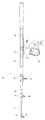
本願発明の適用について、キス釣り等に使用される投げ竿に基づいて説明する。図1及び図2示すように、穂先竿1、二番竿2、元竿3を並継式に連結して釣り竿Aを構成するとともに、穂先竿1、二番竿2に夫々釣糸ガイド4を装着するとともに、元竿3にリール6を取り付けるリールシート5を取り付けてある。
The application of the present invention will be described based on a throwing rod used for kiss fishing and the like. As shown in FIGS. 1 and 2, the
元竿3の所定位置に取付固定用の糸7で固定される装着具の一例としての板状リールシート5について説明する。図2〜図4に示すように、板状リールシート5は、全体が金属で構成されており、竿先側にリール6のリール脚6aを挿入保持する固定フード5Aと竿尻側にリール脚6aを挿入保持解除自在な可動フード5Bとを備え、両フード5A、5Bとを取り付けている細長板状のベースフレーム5Cとで構成してある。そのベースフレーム5Cにおける両フード5A、5Bから突出する竿先端部5a、竿尻端部5b、及び、両フード5A、5Bとの間に位置する中間部5cを、糸7を巻き付けて固定する板状の装着部として形成する。糸7を巻き付けた後、樹脂製の接着剤等を塗布して固定状態を確定する。
A plate-
図4に示すように、板状リールシート5の竿先端部5a、および、竿尻端部5b、中間部5cに形成する切り込み溝5dの方向は、左右端縁から互いに相手側の端縁に向けて入り込む状態に形成してもよい。切り込み溝5dによって切り離された端縁の部分が変形し易くなり、竿外周面への密着性を高めることになる。As shown in FIG. 4, the direction of the
切り込み溝としては、次のような構成にもできる。図2及び図3に示すように、竿先端部5a、および、竿尻端部5bにおける先端部分、更に、中間部5cには、前後方向に入り込む切り込み溝5dが形成されている。この切り込み溝5dが形成されることによって、竿先端部5a、および、竿尻端部5b更に、中間部5cは前記切り込み溝5dの幅を拡縮する状態に変形することが可能になり、元竿3の円形外周面に沿い易く、密着状態を高めることになる。
The cut groove can be configured as follows. As shown in FIGS. 2 and 3, a
このような構成によって、竿先端部5aと竿尻端部5bと中間部5cの取付面と竿外周面とのスベリ現象を抑制し、投げ操作を行う際の異音の発生を抑えるとともに、リールシート5の装着状態が安定し、リールシート5のガタツキを抑制し、投げ操作時の釣り人が感じる違和感を抑えることができる。
With such a configuration, the sliding phenomenon between the attachment surface of the
穂先竿1、二番竿2の所定位置に取付固定用の糸7で固定される装着具の一例としての釣糸ガイド4について説明する。図5に示すように、釣糸ガイド4は、竿から離れる先端部に釣り糸挿通用の孔4Aを備えるとともに、その先端部から前後に二本の脚部4B、4Bを延出してある。その延出された二本の脚部4B、4Bを、糸7を巻き付けて固定する板状の装着部として形成する。糸7を巻き付けた後、樹脂製の接着剤等を塗布して固定状態を確定する。
A
図5に示すように、二本の脚部4B、4Bにおける竿外周面に対する取付部には、前後方向に入り込む切り込み溝4aが形成されている。この切り込み溝4aが形成されることによって、脚部4B、4Bは前記切り込み溝4aの幅を拡縮する状態に変形することが可能になり、元竿3の円形外周面に沿い易く、密着状態を高めることになる。
As shown in FIG. 5, the
このような構成によって、脚部4B、4Bの取付面と竿外周面とのスベリ現象を抑制し、投げ操作を行う際の異音の発生を抑えるとともに、釣糸ガイド4の装着状態が安定し、釣糸ガイド4のガタツキを抑制し、投げ操作時の釣り人が感じる違和感を抑えることができる。
With such a configuration, the sliding phenomenon between the mounting surfaces of the
〔別実施の形態〕
(1) 前記した切り込み溝を施す対象としては、板状リールシート5か釣糸ガイド4のいずれか一方であってもよい。
[Another embodiment]
(1) The object to be provided with the above-described cut groove may be either the plate-
4、5 竿装着具
4B、5a、5b、5c 装着部
4a、5d 切り込み溝
7 糸
4, 5
Claims (2)
前記装着部を、リール脚を挿入保持するフードを取り付けているベースフレームにおける竿先端部、竿尻端部、及び、それらの間に位置する中間部とに設け、前記竿先端部、前記竿尻端部、及び、前記中間部における、夫々の左右端縁に、その端縁の部分を切り離すように、左右端縁から互いに相手側の端縁に向けて入り込む複数の切り込み溝を形成してある板状リールシート。
A plate-shaped reel sheet that has a mounting portion that is mounted at a predetermined position on the outer peripheral surface of the heel, and that is wound around the mounting portion and fixed to the outer peripheral surface of the heel by winding a thread for attachment and fixing;
The mounting portion is provided at a heel tip portion, a buttock end portion, and an intermediate portion located therebetween in a base frame to which a hood for inserting and holding a reel leg is attached. A plurality of cut grooves are formed on the left and right end edges of the end portion and the intermediate portion so as to cut off the end edge portions from the left and right end edges toward the other end edge. Plate reel sheet.
Priority Applications (1)
| Application Number | Priority Date | Filing Date | Title |
|---|---|---|---|
| JP2004339076A JP4753279B2 (en) | 2004-11-24 | 2004-11-24 | A plate reel seat and a fishing rod equipped with the plate reel seat |
Applications Claiming Priority (1)
| Application Number | Priority Date | Filing Date | Title |
|---|---|---|---|
| JP2004339076A JP4753279B2 (en) | 2004-11-24 | 2004-11-24 | A plate reel seat and a fishing rod equipped with the plate reel seat |
Publications (2)
| Publication Number | Publication Date |
|---|---|
| JP2006141341A JP2006141341A (en) | 2006-06-08 |
| JP4753279B2 true JP4753279B2 (en) | 2011-08-24 |
Family
ID=36621703
Family Applications (1)
| Application Number | Title | Priority Date | Filing Date |
|---|---|---|---|
| JP2004339076A Expired - Fee Related JP4753279B2 (en) | 2004-11-24 | 2004-11-24 | A plate reel seat and a fishing rod equipped with the plate reel seat |
Country Status (1)
| Country | Link |
|---|---|
| JP (1) | JP4753279B2 (en) |
Families Citing this family (1)
| Publication number | Priority date | Publication date | Assignee | Title |
|---|---|---|---|---|
| KR101391116B1 (en) * | 2013-07-23 | 2014-04-30 | 후지코교 가부시기가이샤 | Fishing line guide, reel seat and fishing rod including the same |
Family Cites Families (6)
| Publication number | Priority date | Publication date | Assignee | Title |
|---|---|---|---|---|
| JPS5130308Y2 (en) * | 1973-11-10 | 1976-07-30 | ||
| JPS5236178U (en) * | 1975-09-03 | 1977-03-14 | ||
| JPS53135391U (en) * | 1977-03-30 | 1978-10-26 | ||
| JPS55180378U (en) * | 1979-06-14 | 1980-12-25 | ||
| JPS5758946Y2 (en) * | 1979-06-20 | 1982-12-16 | ||
| JPH0810277Y2 (en) * | 1989-10-31 | 1996-03-29 | 島野工業株式会社 | Fishing rod |
-
2004
- 2004-11-24 JP JP2004339076A patent/JP4753279B2/en not_active Expired - Fee Related
Also Published As
| Publication number | Publication date |
|---|---|
| JP2006141341A (en) | 2006-06-08 |
Similar Documents
| Publication | Publication Date | Title |
|---|---|---|
| JP4674132B2 (en) | Belt adjuster | |
| JP6147804B2 (en) | Ingrown nail corrector | |
| US8819944B2 (en) | Bladed tool with a bent blade-retaining shank | |
| JPH0861334A (en) | Clip | |
| EP3078263B1 (en) | Fixing structure for fishing line guide, and fishing rod | |
| JP5890269B2 (en) | Fishing line guide | |
| JP4753279B2 (en) | A plate reel seat and a fishing rod equipped with the plate reel seat | |
| JP4977908B2 (en) | Anchor type clip | |
| JP2006223186A (en) | Fixing structure of plate-like reel sheet and fishing rod having the same fixing structure | |
| JP4627010B2 (en) | fishing rod | |
| JP2009011784A (en) | Clip for endoscope | |
| JP4988397B2 (en) | Arm piece cover | |
| JP5150592B2 (en) | Fishing line guide | |
| JP2014027885A (en) | Fishing rod | |
| JP4400824B2 (en) | A sound-reducing material for a plate-shaped reel sheet and a fishing rod provided with the sound-reducing material | |
| JP3139298U (en) | fishing rod | |
| JP2916429B2 (en) | Fishing rod for fishing rod | |
| JP2844526B2 (en) | Fishing rod for fishing rod | |
| JP2020031581A (en) | fishing rod | |
| JP6647571B2 (en) | Wiring clamp | |
| JP5366742B2 (en) | Fishing line guide | |
| US20060101703A1 (en) | Reel seat for a fishing rod | |
| JP2602626Y2 (en) | Through fishing rod | |
| JP4033397B2 (en) | Fishing rod with outer guide | |
| JP2008150745A (en) | Helmet interior member |
Legal Events
| Date | Code | Title | Description |
|---|---|---|---|
| A621 | Written request for application examination |
Free format text: JAPANESE INTERMEDIATE CODE: A621 Effective date: 20071025 |
|
| RD04 | Notification of resignation of power of attorney |
Free format text: JAPANESE INTERMEDIATE CODE: A7424 Effective date: 20090827 |
|
| RD02 | Notification of acceptance of power of attorney |
Free format text: JAPANESE INTERMEDIATE CODE: A7422 Effective date: 20090916 |
|
| A977 | Report on retrieval |
Free format text: JAPANESE INTERMEDIATE CODE: A971007 Effective date: 20091008 |
|
| A131 | Notification of reasons for refusal |
Free format text: JAPANESE INTERMEDIATE CODE: A131 Effective date: 20091016 |
|
| A521 | Request for written amendment filed |
Free format text: JAPANESE INTERMEDIATE CODE: A523 Effective date: 20091201 |
|
| A131 | Notification of reasons for refusal |
Free format text: JAPANESE INTERMEDIATE CODE: A131 Effective date: 20100701 |
|
| A521 | Request for written amendment filed |
Free format text: JAPANESE INTERMEDIATE CODE: A523 Effective date: 20100820 |
|
| A131 | Notification of reasons for refusal |
Free format text: JAPANESE INTERMEDIATE CODE: A131 Effective date: 20101210 |
|
| A521 | Request for written amendment filed |
Free format text: JAPANESE INTERMEDIATE CODE: A523 Effective date: 20101217 |
|
| TRDD | Decision of grant or rejection written | ||
| A01 | Written decision to grant a patent or to grant a registration (utility model) |
Free format text: JAPANESE INTERMEDIATE CODE: A01 Effective date: 20110519 |
|
| A01 | Written decision to grant a patent or to grant a registration (utility model) |
Free format text: JAPANESE INTERMEDIATE CODE: A01 |
|
| A61 | First payment of annual fees (during grant procedure) |
Free format text: JAPANESE INTERMEDIATE CODE: A61 Effective date: 20110519 |
|
| FPAY | Renewal fee payment (event date is renewal date of database) |
Free format text: PAYMENT UNTIL: 20140603 Year of fee payment: 3 |
|
| R150 | Certificate of patent or registration of utility model |
Free format text: JAPANESE INTERMEDIATE CODE: R150 Ref document number: 4753279 Country of ref document: JP Free format text: JAPANESE INTERMEDIATE CODE: R150 |
|
| R250 | Receipt of annual fees |
Free format text: JAPANESE INTERMEDIATE CODE: R250 |
|
| R250 | Receipt of annual fees |
Free format text: JAPANESE INTERMEDIATE CODE: R250 |
|
| R250 | Receipt of annual fees |
Free format text: JAPANESE INTERMEDIATE CODE: R250 |
|
| R250 | Receipt of annual fees |
Free format text: JAPANESE INTERMEDIATE CODE: R250 |
|
| R250 | Receipt of annual fees |
Free format text: JAPANESE INTERMEDIATE CODE: R250 |
|
| R250 | Receipt of annual fees |
Free format text: JAPANESE INTERMEDIATE CODE: R250 |
|
| R250 | Receipt of annual fees |
Free format text: JAPANESE INTERMEDIATE CODE: R250 |
|
| R250 | Receipt of annual fees |
Free format text: JAPANESE INTERMEDIATE CODE: R250 |
|
| LAPS | Cancellation because of no payment of annual fees |