JP4988397B2 - Arm piece cover - Google Patents
Arm piece cover Download PDFInfo
- Publication number
- JP4988397B2 JP4988397B2 JP2007074696A JP2007074696A JP4988397B2 JP 4988397 B2 JP4988397 B2 JP 4988397B2 JP 2007074696 A JP2007074696 A JP 2007074696A JP 2007074696 A JP2007074696 A JP 2007074696A JP 4988397 B2 JP4988397 B2 JP 4988397B2
- Authority
- JP
- Japan
- Prior art keywords
- arm piece
- arm
- cover
- retainer
- piece cover
- Prior art date
- Legal status (The legal status is an assumption and is not a legal conclusion. Google has not performed a legal analysis and makes no representation as to the accuracy of the status listed.)
- Expired - Fee Related
Links
Images


Description
本発明は、ワイパーアームのアームピースに装着されるアームピースカバーに関する。 The present invention relates to an arm piece cover attached to an arm piece of a wiper arm.
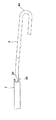
ワイパー装置に備えられるワイパーアームとしては、リテーナにアームピースを保持したものが知られている。図6、図7には、このようなワイパーアーム1を示す。図示されるように、ワイパーアーム1は、アームヘッド2と、アームヘッド2に回動可能に連結されたリテーナ3と、リテーナ3に保持されたアームピース4とから構成される。
As a wiper arm provided in the wiper device, one in which an arm piece is held by a retainer is known. 6 and 7 show such a
このようなワイパーアーム1においては、アームピース4は、リテーナ3の先端3Bから前方に延び出すようになっている。このため、リテーナ3の先端3Bにおいて、リテーナ3とアームピース4の間には、リテーナ3の厚み分の段差が生じてしまい、この段差の存在は、ワイパーアーム1の外観を損ねていた。
In such a
本発明はこのような問題点に着目してなされたもので、ワイパーアームのアームピースに装着されるアームピースカバーであって、ワイパーアームの外観を向上させうるものを提供することを目的とする。 The present invention has been made paying attention to such problems, and it is an object of the present invention to provide an arm piece cover that is attached to an arm piece of a wiper arm, and that can improve the appearance of the wiper arm. .
本発明は、アームピースをリテーナで保持するワイパーアームに用いられ、前記リテーナの先端に隣接して配置され、前記アームピースに装着され得るアームピースカバーにおいて、前記アームピースの上側に当接して配置可能な上面と、前記アームピースの下側に当接して配置可能な下面と、前記アームピースの一方の側部に当接して配置可能な第1の側面と、前記アームピースの他方の側部に当接して配置可能な第2の側面とを備え、前記上面と前記下面の間に第1の隙間を形成し、前記下面と前記第2の側面との間に前記第1の隙間から連なる第2の隙間を形成し、前記アームピースが、前記第1及び第2の隙間を通して、前記上面と下面の間及び前記第1と第2の側面の間にはめ込まれ得るようにした。 The present invention is used in a wiper arm that holds an arm piece by a retainer, and is disposed adjacent to a tip of the retainer, and is disposed in contact with an upper side of the arm piece in an arm piece cover that can be attached to the arm piece. A possible upper surface, a lower surface that can be placed in contact with the lower side of the arm piece, a first side surface that can be placed in contact with one side of the arm piece, and the other side of the arm piece And a second side surface that can be disposed in contact with the first surface, forming a first gap between the upper surface and the lower surface, and continuing from the first gap between the lower surface and the second side surface. A second gap is formed so that the arm piece can be fitted between the upper surface and the lower surface and between the first and second side surfaces through the first and second gaps.
前記上面は、前記リテーナの先端に当接して配置可能であってもよい。
前記上面の厚みは、前記リテーナの上面と前記アームピースの上面の間の段差の大きさと略等しくしてもよい。
The upper surface may be disposed in contact with a tip of the retainer.
The thickness of the upper surface may be substantially equal to the size of the step between the upper surface of the retainer and the upper surface of the arm piece.
前記第一の側面の厚みは、前記リテーナの側面と前記アームピースの側面の間の段差の大きさと略等しくしてもよい。
前記第2の側面の前記下面と向き合う端辺を傾斜させてもよい。
The thickness of the first side surface may be substantially equal to the size of the step between the side surface of the retainer and the side surface of the arm piece.
You may incline the edge which faces the said lower surface of a said 2nd side surface.
前記下面又は前記上面に、前記アームピースに対する前記アームピースカバーの位置を固定するための位置決め手段を備えてもよい。
前記位置決め手段は、前記アームピースに設けられたダボ又はダボ孔に嵌合するダボ孔又はダボであってもよい。
You may provide the positioning means for fixing the position of the said arm piece cover with respect to the said arm piece in the said lower surface or the said upper surface.
The positioning means may be a dowel hole or a dowel that fits into a dowel or dowel hole provided in the arm piece.
前記アームピースカバーは、弾性部材で形成されていてもよい。 The arm piece cover may be formed of an elastic member.
本発明によれば、アームピースカバー(例えばアームピースカバー10)は、上面(例えば上面11)と下面(例えば下面12)でアームピース(例えばアームピース4)を上下から挟持して保持し、第1の側面(例えば側面13)と第2の側面(例えば側面14)でアームピースを左右から挟持して保持するので、アームピースに対して脱落しにくく装着できる。また、第1の隙間(例えば隙間15)及び第2の隙間(例えば隙間16)内にアームピースをはめ込むことにより、アームピースカバーのアームピースへの装着がなされるので、装着作業は容易である。 According to the present invention, the arm piece cover (for example, the arm piece cover 10) holds and holds the arm piece (for example, the arm piece 4) from above and below on the upper surface (for example, the upper surface 11) and the lower surface (for example, the lower surface 12). Since the arm piece is sandwiched and held from the left and right by the one side surface (for example, the side surface 13) and the second side surface (for example, the side surface 14), it can be attached to the arm piece so as not to drop off. Further, since the arm piece is attached to the arm piece by fitting the arm piece into the first gap (for example, the gap 15) and the second gap (for example, the gap 16), the mounting work is easy. .
また、上面の厚みを、リテーナ(例えばリテーナ3)の上面とアームピースの上面の間の段差の大きさと略等しくし、第1の側面の厚みを、リテーナの側面とアームピースの側面の間の段差の大きさと略等しくすれば、アームピースカバーとリテーナは、段差無くなだらかに連なるようにできるので、アームピースカバーの先端部(第1の側面13の延長部13A及び第2の側面13)のデザインを整えることにより、ワイパーアーム(例えばワイパーアーム1)全体を段差のない形状とすることができ、ワイパーアームの外観が向上する。
Further, the thickness of the upper surface is made substantially equal to the size of the step between the upper surface of the retainer (for example, retainer 3) and the upper surface of the arm piece, and the thickness of the first side surface is set between the side surface of the retainer and the side surface of the arm piece. If the size of the step is substantially equal, the arm piece cover and the retainer can be smoothly connected without a step, so that the tip of the arm piece cover (the
また、第2の側面の下面と向き合う端辺(例えば傾斜部14A)を傾斜させれば、第1の隙間と第2の隙間の作る角度を小さくできるので、第1の隙間及び第2の隙間にアームピースをはめ込み易くなり、アームピースカバーの装着が更に容易となる。
In addition, if the edge (for example, the
また、下面又は上面に、アームピースに対するアームピースカバーの位置を固定するための位置決め手段(例えばアームピース4のダボ4Bに嵌合するダボ孔12A)を備えれば、アームピースカバーは、アームピースに対して適切な位置に正しく配置されるとともに、アームピースカバーのアームピースからの脱落は、より確実に防止できる。
Further, if positioning means for fixing the position of the arm piece cover with respect to the arm piece (for example, a
以下、添付図面を参照して本発明の各実施形態を説明する。
図1、図2には、本実施形態のワイパーアームピースを装着したワイパーアームの全体構成を示す。図示されるように、ワイパーアーム1は、アームヘッド2と、リテーナ3と、アームピース4とから構成される。
Hereinafter, embodiments of the present invention will be described with reference to the accompanying drawings.
1 and 2 show the overall configuration of a wiper arm equipped with the wiper arm piece of the present embodiment. As illustrated, the
アームヘッド2は、ワイパーアーム1の基端側を構成する部分で、その基端は、リンク機構(図示せず)を介して駆動モータ(図示せず)に連結される連結部2Aとなっている。一方、アームヘッド2の先端部2Bには、リテーナ3の基端部3Aが回動可能に連結されている。
The
リテーナ3は、アームピース4の基端側を収容して保持する部材で、その先端部3Bからアームピース4の先端側が突出している。アームピース4は、ワイパーブレード(図示せず)と連結される部材で、先端にU字型のフック部4Aを備えている。このフック部4Aがワイパーブレードの装着部に係合することにより、ワイパーアーム1とワイパーブレードの連結がなされる。
The
アームピース4には、リテーナ3の先端3Bと隣接する位置に、アームピースカバー10が装着される。アームピースカバー10は、例えば樹脂等の弾性部材で形成されたものである。
An
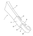
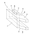
図3には、ワイパーアーム1のアームピースカバー10周辺部分を示す。また、図4には、アームピースカバー10を単体で示す。図示されるように、アームピースカバー10は、上面11と、下面12と、第1の側面13と、第2の側面14とから構成される。
In FIG. 3, the
上面11は、アームピースカバー10がアームピース4に装着されたときにアームピース4の上側に当接して配置される部分で、略長方形の板状の部分である。上面11の厚みは、アームピース4の上面とリテーナ3の上面との間の段差dと略等しくなっている。これにより、アームピースカバー10がアームピース4に装着されたときに、リテーナ3の上面とアームピースカバー10の上面11が、段差無くなだらかに連なるようになっている。
The
第1の側面13は、アームピースカバー10がアームピース4に装着されたときにアームピース4の一方の側部に当接して配置される部分で、上面11の一方の側部から下方に向けて略直角に延び出している。側面13の先端部(アームピース4への装着時にリテーナ3と反対側に配置される端部)は、上面11より前方に延び出す延長部13Aとなっている。延長部13の上面は、前方に向けてなだらかに傾斜した形状となっている。また、側面13の厚みは、アームピース4の側面とリテーナ3の側面との間の段差と略等しくなっている。これにより、アームピースカバー10がアームピース4に装着されたときに、リテーナ3の側面とアームピースカバー10の側面13は、段差無くなだらかに連なるようになっている。
The
下面12は、アームピースカバー10がアームピース4に装着されたときにアームピース4の下側に当接して配置される略長方形の板状の部分で、側面13の下端部から略直角に、上面11と同じ側に延び出している。下面12は、上面11と略同じ幅を有する一方で、その長さ(アームピース4の長手方向の幅)は、上面11の略半分程度となっており、アームピースカバー10の基端側(アームピース4への装着時にリテーナ3と当接して配置される側)に配置されている。また、下面12は、上面11との間にアームピース4をちょうど挟み込める空間が形成されるように、上面11からアームピース4の厚み程度の間隔をもって、上面11と平行に配置されている。これにより、アームピースカバー10の側部には、上面11と下面12の間の隙間15が形成されている。
The
下面12には、ダボ孔12Aが形成されている。図5に示すように、アームピース4の下面には、ダボ4Bが形成されている。アームピースカバー10がアームピース4に装着されたとき、下面12のダボ孔12Aに、アームピース4のダボ4Bが嵌合する。これにより、アームピースカバー10のアームピース4の長手方向への動きが制限され、アームピースカバー10の脱落が防止される。
A
図4に示すように、第2の側面14は、アームピースカバー10がアームピース4に装着されたときにアームピース4の側面13と当接する側面と反対側の側面に当接する部分であり、上面11の側面13と反対側の側部から下方に向けて略直角に延び出している。側面14は、略平行四辺形形状の板部材で、そのアームピース4の長手方向の幅は、上面11の半分以下となっており、上面11の前端付近から前方に向けて延び出している。これにより、下面11の前端と、側面14の後端辺である傾斜部14Aとの間に、アームピース4が挿入されうる隙間16が形成されている。また、側面14の上面11よりも前方に延び出した部分は、その上面が前方に向けてなだらかに傾斜した形状となっており、第1の側面の延長部13Aと、略左右対称となっている。
As shown in FIG. 4, the
つぎに、本実施形態のアームピースカバー10のアームピース4への装着方法について説明する。アームピースカバー10のアームピース4への装着時には、アームピースカバー10の第2の側面14側を、アームピース4の一方の側部に向けて配置し、アームピースカバー10の隙間15及び隙間16にアームピース10を挿入していく。この場合、アームピースカバー10は、樹脂等の弾性部材で形成されているので、適度に変形して、アームピース4を隙間15及び隙間16内に導入していくことができる。また、側面14の傾斜部14Aは、前方に向けて傾斜しているので、隙間15と隙間16は小さな角度でなだらかに連なっており、アームピース4の挿入は、側面14との干渉により阻害されることなくスムーズに行える。
Next, a method for mounting the
このようにアームピース4をアームピースカバー10の隙間15及び隙間16に対して挿入していくと、アームピース4は、側面14を乗り越えて行き、上下方向には上面11と下面12の間に、幅方向には側面13Aと側面14Aとの間に、それぞれ配置されて保持される。また、アームピース4のダボ4Bが、アームピースカバー10のダボ孔12Aに嵌合することにより、アームピース4の長手方向へのアームピースカバー10の位置決めがなされる。これにより、アームピースカバー10は、その上面11及び下面12の後端がリテーナ3の前端3Bに当接する位置に正しく配置され、リテーナ3とアームピースカバー10が段差無くなだらかに連なった状態となる。
When the arm piece 4 is inserted into the
以上のように、本実施形態のアームピースカバー10によれば、アームピースカバー10の上面11及び側面13の厚みが、リテーナ3とアームピース4の間の段差の大きさと略等しくなっているので、アームピースカバー10とリテーナ3は段差無くなだらかに連なるようにできる。さらに、第1の側面13の延長部13A及び第2の側面13の形状は、前方に向けてなだらかに傾斜した形状となっているので、ワイパーアーム1は全体として段差のない形状となる。よって、ワイパーアーム1の外観が向上する。
As described above, according to the arm piece cover 10 of the present embodiment, the thickness of the
また、アームピースカバー10の装着は、アームピースカバー10の隙間15及び16にワイパーアーム4をはめ込むだけで行えるので、極めて容易である。
また、アームピースカバー10は、上面11及び下面12でアームピース4を上下から挟持して保持するとともに、側面13及び側面14でアームピース4を左右から挟持して保持するようになっているので、アームピースカバー10に対して脱落しにくい。さらに、アームピースカバー10の下面12Aに形成されたダボ孔12Aに、アームピース4のダボ4Bが嵌合するので、アームピースカバー10は、アームピース4に対して適切な位置に正しく配置されるとともに、アームピースカバー10のアームピース4からの脱落は、より確実に防止できる。
Further, the arm piece cover 10 can be mounted by simply fitting the wiper arm 4 into the
In addition, the arm piece cover 10 holds the arm piece 4 from above and below by holding the
なお、上記実施形態では、アームピースカバー10の下面12Aにダボ孔12Aを設け、アームピース4の下面にダボ4Bを設けたが、本発明の範囲は、このような形態に限られない。例えば、アームピース10の下面12Aにダボを設け、アームピース4の下面にダボ孔を設けることも可能である。また、アームピース10の上面12Aにダボ又はダボ孔を設け、アームピース4の上面にダボ孔又はダボを設けるようにしても良い。さらに、アームピースカバー10とアームピース4間の位置決め手段は、ダボとダボ孔に限られず、アームピース4の長手方向へのアームピースカバー10の動きを規制しうる任意の構成が含まれる。
In the above embodiment, the
1 ワイパーアーム
2 アームヘッド
3 リテーナ
3B リテーナの前端
4 アームピース
4B ダボ
10 アームピースカバー
11 上面
12 下面
12A ダボ孔
13 第1の側面
14 第2の側面
14A 傾斜部
15 隙間
16 隙間
DESCRIPTION OF
Claims (8)
前記アームピースの上側に当接して配置可能な上面と、
前記アームピースの下側に当接して配置可能な下面と、
前記アームピースの一方の側部に当接して配置可能な第1の側面と、
前記アームピースの他方の側部に当接して配置可能な第2の側面と
を備え、
前記上面と前記下面の間に第1の隙間を形成し、
前記第2の側面は、前記下面と向き合う端辺を傾斜させた傾斜部を有しており、
前記下面と前記第2の側面の傾斜部との間に、前記第1の隙間から連なる第2の隙間を形成し、
前記アームピースが、前記第1及び第2の隙間を通して、前記上面と下面の間及び前記第1と第2の側面の間にはめ込まれ得るようにしたアームピースカバー。 In an arm piece cover that is used for a wiper arm that holds an arm piece by a retainer, and that is disposed adjacent to a tip of the retainer and can be attached to the arm piece,
An upper surface that can be disposed in contact with the upper side of the arm piece;
A lower surface that can be placed in contact with the lower side of the arm piece;
A first side surface that can be disposed in contact with one side of the arm piece;
A second side surface that can be disposed in contact with the other side of the arm piece,
Forming a first gap between the upper surface and the lower surface;
The second side surface has an inclined portion with an inclined end facing the lower surface,
Between the lower surface and the inclined portion of the second side to form a second gap communicating from said first gap,
An arm piece cover in which the arm piece can be fitted between the upper surface and the lower surface and between the first and second side surfaces through the first and second gaps.
前記アームピースは、ワイパーブレードと連結される部材で、先端にU字型のフック部を備えており、The arm piece is a member connected to the wiper blade, and has a U-shaped hook at the tip.
前記アームピースが、前記第1及び第2の隙間を通して、前記上面と下面の間及び前記第1と第2の側面の間にはめ込まれたとき、前記アームピースの前記フック部は、前記アームピースカバーの前記上面、前記下面、前記第1の側面、及び第2の側面を超えて延びる請求項1から請求項7のいずれか1つに記載のアームピースカバー。When the arm piece is fitted between the upper surface and the lower surface and between the first and second side surfaces through the first and second gaps, the hook portion of the arm piece is The arm piece cover according to any one of claims 1 to 7, wherein the arm piece cover extends beyond the upper surface, the lower surface, the first side surface, and the second side surface of the cover.
Priority Applications (1)
| Application Number | Priority Date | Filing Date | Title |
|---|---|---|---|
| JP2007074696A JP4988397B2 (en) | 2007-03-22 | 2007-03-22 | Arm piece cover |
Applications Claiming Priority (1)
| Application Number | Priority Date | Filing Date | Title |
|---|---|---|---|
| JP2007074696A JP4988397B2 (en) | 2007-03-22 | 2007-03-22 | Arm piece cover |
Publications (2)
| Publication Number | Publication Date |
|---|---|
| JP2008230471A JP2008230471A (en) | 2008-10-02 |
| JP4988397B2 true JP4988397B2 (en) | 2012-08-01 |
Family
ID=39903777
Family Applications (1)
| Application Number | Title | Priority Date | Filing Date |
|---|---|---|---|
| JP2007074696A Expired - Fee Related JP4988397B2 (en) | 2007-03-22 | 2007-03-22 | Arm piece cover |
Country Status (1)
| Country | Link |
|---|---|
| JP (1) | JP4988397B2 (en) |
Families Citing this family (4)
| Publication number | Priority date | Publication date | Assignee | Title |
|---|---|---|---|---|
| JP4436393B2 (en) | 2007-09-11 | 2010-03-24 | 本田技研工業株式会社 | Wiper device |
| JP7194652B2 (en) * | 2019-07-31 | 2022-12-22 | 株式会社ミツバ | wiper arm |
| CN114025999B (en) * | 2019-07-31 | 2024-10-11 | 株式会社美姿把 | Wiper arm and method for manufacturing same |
| JP7194653B2 (en) * | 2019-07-31 | 2022-12-22 | 株式会社ミツバ | Wiper arm and manufacturing method thereof |
Family Cites Families (4)
| Publication number | Priority date | Publication date | Assignee | Title |
|---|---|---|---|---|
| JP4091493B2 (en) * | 2003-07-08 | 2008-05-28 | アスモ株式会社 | Connecting device and wiper blade |
| JP2007008279A (en) * | 2005-06-29 | 2007-01-18 | Mitsuba Corp | Wiper device |
| JP2007276669A (en) * | 2006-04-07 | 2007-10-25 | Asmo Co Ltd | Vehicular wiper, and cover member |
| JP4922788B2 (en) * | 2007-02-28 | 2012-04-25 | 株式会社ミツバ | Wiper device |
-
2007
- 2007-03-22 JP JP2007074696A patent/JP4988397B2/en not_active Expired - Fee Related
Also Published As
| Publication number | Publication date |
|---|---|
| JP2008230471A (en) | 2008-10-02 |
Similar Documents
| Publication | Publication Date | Title |
|---|---|---|
| JP4988397B2 (en) | Arm piece cover | |
| JP2010019364A (en) | Pad clip for disk brake device | |
| JP2015012151A (en) | Shield case grip member | |
| JP4405780B2 (en) | Mask string length adjustment member | |
| KR101248050B1 (en) | Slider Needle With Built-in Center Strip | |
| JP3543804B2 (en) | Connector cover | |
| JP4577285B2 (en) | Temporary shaft of linear motion guide device | |
| JP3806586B2 (en) | Semiconductor laser device | |
| JP4144266B2 (en) | Cab stay stopper | |
| CN103039135B (en) | PCB Holder | |
| JP5371049B2 (en) | clip | |
| WO2020096005A1 (en) | Fastener | |
| JP2010263932A (en) | Orthodontic bracket | |
| WO2008065770A1 (en) | Electric-wire holder | |
| JP5323227B2 (en) | Pad clip for disc brake device | |
| JP2008303935A (en) | Gap adjustment shim | |
| JP4853766B2 (en) | Electronic keyboard instrument key guide structure | |
| JP6604252B2 (en) | Cover member, hard disk unit, and cover member forming method | |
| JP4893461B2 (en) | Electronic device protection plate | |
| JP4148963B2 (en) | Semiconductor laser device | |
| JP4446938B2 (en) | Semiconductor laser device | |
| JP5195411B2 (en) | Connector fixture | |
| JP5606287B2 (en) | Element mounting structure | |
| JP6532782B2 (en) | magnet catch | |
| JP2009060732A (en) | Bendable protector for flexible flat circuit body |
Legal Events
| Date | Code | Title | Description |
|---|---|---|---|
| A621 | Written request for application examination |
Free format text: JAPANESE INTERMEDIATE CODE: A621 Effective date: 20100323 |
|
| RD04 | Notification of resignation of power of attorney |
Free format text: JAPANESE INTERMEDIATE CODE: A7424 Effective date: 20110912 |
|
| A977 | Report on retrieval |
Free format text: JAPANESE INTERMEDIATE CODE: A971007 Effective date: 20111215 |
|
| A131 | Notification of reasons for refusal |
Free format text: JAPANESE INTERMEDIATE CODE: A131 Effective date: 20120112 |
|
| A521 | Request for written amendment filed |
Free format text: JAPANESE INTERMEDIATE CODE: A523 Effective date: 20120307 |
|
| TRDD | Decision of grant or rejection written | ||
| A01 | Written decision to grant a patent or to grant a registration (utility model) |
Free format text: JAPANESE INTERMEDIATE CODE: A01 Effective date: 20120328 |
|
| A01 | Written decision to grant a patent or to grant a registration (utility model) |
Free format text: JAPANESE INTERMEDIATE CODE: A01 |
|
| A61 | First payment of annual fees (during grant procedure) |
Free format text: JAPANESE INTERMEDIATE CODE: A61 Effective date: 20120426 |
|
| R150 | Certificate of patent or registration of utility model |
Ref document number: 4988397 Country of ref document: JP Free format text: JAPANESE INTERMEDIATE CODE: R150 Free format text: JAPANESE INTERMEDIATE CODE: R150 |
|
| FPAY | Renewal fee payment (event date is renewal date of database) |
Free format text: PAYMENT UNTIL: 20150511 Year of fee payment: 3 |
|
| R250 | Receipt of annual fees |
Free format text: JAPANESE INTERMEDIATE CODE: R250 |
|
| R250 | Receipt of annual fees |
Free format text: JAPANESE INTERMEDIATE CODE: R250 |
|
| R250 | Receipt of annual fees |
Free format text: JAPANESE INTERMEDIATE CODE: R250 |
|
| R250 | Receipt of annual fees |
Free format text: JAPANESE INTERMEDIATE CODE: R250 |
|
| R250 | Receipt of annual fees |
Free format text: JAPANESE INTERMEDIATE CODE: R250 |
|
| S531 | Written request for registration of change of domicile |
Free format text: JAPANESE INTERMEDIATE CODE: R313531 |
|
| S533 | Written request for registration of change of name |
Free format text: JAPANESE INTERMEDIATE CODE: R313533 |
|
| R350 | Written notification of registration of transfer |
Free format text: JAPANESE INTERMEDIATE CODE: R350 |
|
| R250 | Receipt of annual fees |
Free format text: JAPANESE INTERMEDIATE CODE: R250 |
|
| LAPS | Cancellation because of no payment of annual fees |