JP4752139B2 - Manufacturing method of thermal fuse - Google Patents
Manufacturing method of thermal fuse Download PDFInfo
- Publication number
- JP4752139B2 JP4752139B2 JP2001170917A JP2001170917A JP4752139B2 JP 4752139 B2 JP4752139 B2 JP 4752139B2 JP 2001170917 A JP2001170917 A JP 2001170917A JP 2001170917 A JP2001170917 A JP 2001170917A JP 4752139 B2 JP4752139 B2 JP 4752139B2
- Authority
- JP
- Japan
- Prior art keywords
- manufacturing
- thermal fuse
- lead
- fusible alloy
- tip
- Prior art date
- Legal status (The legal status is an assumption and is not a legal conclusion. Google has not performed a legal analysis and makes no representation as to the accuracy of the status listed.)
- Expired - Lifetime
Links
Images
Landscapes
- Fuses (AREA)
Description
【0001】
【発明の属する技術分野】
本発明は、異常加熱等による電子機器など破損等を防止するのに好適に用いられ、可溶合金をヒューズエレメントとする温度ヒューズの製造方法に関するものである。
【0002】
【従来の技術】
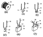
従来の温度ヒューズの製造方法は、図12(a)に示すようにリール28に巻回された線材29を切断して、一本のリード線30とし、図12(b)の様に曲げ部31及び屈曲部32を設け、このリード線30のU形部の先端よりやや内側に可溶合金33を掛渡して載せ、U形部の先端を加熱することにより可溶合金33の両端部をリード線30との接触部分に溶着し、リード線30の可溶合金33より先端側を切断し、このリード線30付き可溶合金33を収納部35を設けたケース34内に封入することを特徴とする温度ヒューズの製造方法が知られている(例えば特開昭62−131429号公報)。
【0003】
【発明が解決しようとする課題】
前記従来の構成では、可溶合金33とリード線30の溶着部近傍を切断する為、リード線30の切断時に可溶合金33とリード線30の溶着部に応力が発生しやすく、溶着部にクラック、破断が発生しやすいため歩留りが悪いとともに、計時変化が起こりやすく、長期間の使用によって所望の溶断特性などを得ることができないという問題点があった。
【0004】
更に可溶合金33とリード線30との溶着部の他端のリード線30部分は自由に動くことが出来る不安定な状態にあり、リード線30切断後に工程内で可溶合金33とリード線30の熔着部にクラック、破断が発生しやすいため前述と同様に歩留りが悪く、長期間の使用に耐えかねるという問題点もあった。
【0005】
また、可溶合金33をリード線30上の対向部分に置いて加熱溶着する為、可溶合金33の厚さにリード線30の厚さを加えた厚さの溶着部を収納できるケースが必要となり、より薄いケースの小型高性能な温度ヒューズとすることが困難であった。
【0006】
更に、リード線30部分を電子機器内などに設けられたプリント基板に挿入する場合、プリント基板への挿入不良を発生しやすいという問題点があった。
【0007】
本発明は前記従来の課題を解決するもので、プリント基板への挿入性を向上させる温度ヒューズを提供することを目的としている。
【0008】
本発明は、小型化特に薄型化が可能な温度ヒューズの製造方法を提供することを目的としている。
【0009】
本発明は製造上において歩留まりの向上を目的とする温度ヒューズの製造方法を提供することを目的としている。
【0010】
本発明は、長期間の使用によっても、所望の特性を得ることができる温度ヒューズの製造方法を提供することを目的としている。
【0011】
【課題を解決するための手段】
本発明は、底部と、底部の両端から同一方向に折り曲げられたリード部と、リード部において底部側と反対側の先端に設けられた先端部とを有したリード線を形成し、先端部間に可溶合金を溶接した後、底部もしくは底部近傍のリード部を切断した。
【0012】
【発明の実施の形態】
【0015】
請求項1記載の発明は、底部と、前記底部の両端から同一方向に折り曲げられたリード部と、前記リード部において前記底部側と反対側の先端に設けられた先端部とを有したリード線を形成し、前記先端部間に可溶合金を溶接した後、前記底部もしくは前記リード部を切断することを特徴とする温度ヒューズの製造方法とすることで、可溶合金と先端部の熔着部から離れた位置で、リード部を切り離しているので、熔着部に応力やクラックが入るのを防止でき、製品の歩留まりを向上できる。更には、長期間の使用によって、前述の応力やクラックなどに起因する特性の劣化などを防止できる。
【0016】
請求項2記載の発明は、先端部において互いに対向する対向部間に可溶合金を配置して、前記先端部間に可溶合金を溶接したことを特徴とする請求項1記載の温度ヒューズの製造方法とすることで、リード線の厚みの範囲内に可溶合金の少なくとも一部を配置できるので、薄型化を容易に行うことができる。
【0017】
請求項3記載の発明は、少なくとも先端部の一部に第1のフラックスを塗布した後に、前記第1のフラックス塗布部分に可溶合金を溶接したことを特徴とする請求項1記載の温度ヒューズの製造方法とすることで、可溶合金とリード線の溶接する際に、可溶合金やリード線の酸化などを防止して、強固に接合させ、製造途中において可溶合金がリード線から脱落することはほとんどなく、長期間安定した特性を得ることができる。
【0018】
請求項4記載の発明は、先端部に可溶合金を溶接した後に、前記可溶合金上及び前記可溶合金近傍に第2のフラックスを塗布したことを特徴とする請求項1記載の温度ヒューズの製造方法とすることで、可溶合金の溶断温度に達したときに確実に可溶合金を切断させることができる。
【0019】
請求項5記載の発明は、別途、一端開口の箱状のケースを用意し、前記ケースに前記第2のフラックス塗布部分及びリード線の一部を収納し、熱処理をして前記第2のフラックスを溶かし冷却することで、前記リード線と前記ケースを固定することを特徴とする請求項4記載の温度ヒューズの製造方法とすることで、ケース内に可溶合金付リード線を別途の接合剤を用いることなく、固定できるので生産性が向上する。
【0020】
請求項6記載の発明は、ケース開口に封止材を設け、前記第2のフラックス塗布部分が配置されるケース内部と外界を遮断したことを特徴とする請求項5記載の温度ヒューズの製造方法とすることで、可溶合金が外気と触れ合うことで、特性の劣化を防止でき、しかも水分による溶断特性の劣化を防止できる。
【0021】
請求項7記載の発明は、リード線を所定間隔で搬送フープ材に複数取り付け、その後の工程を経ることを特徴とする請求項1記載の温度ヒューズの製造方法とすることで、搬送フープ材を移動させることで、連続して温度ヒューズを作製でき、生産性を高めることができる。
【0022】
請求項8記載の発明は、搬送フープ材において、リード線間に貫通孔を設け、この貫通孔を搬送フープ材の移動や部材間の位置決めに用いたことを特徴とする請求項7記載の温度ヒューズの製造方法とすることで、製造途中での位置決め等が容易に行うことができ、寸法精度の高い温度ヒューズを作製できる。
【0023】
請求項9記載の発明は、先端部とリード部の間に折り曲げ部を設け、先端部間の間隔をリード部間の間隔よりも狭くしたことを特徴とする請求項1記載の温度ヒューズの製造方法とすることで、可溶合金を短く構成でき感度の向上や可溶合金の使用量を少なくできてコスト的に有利である。
【0024】
以下、本発明の実施の形態について、図面を用いて、その製造工程を示すと共に、その構成について説明する。
【0025】
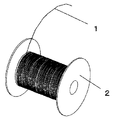
まず図1のようにボビン2に巻かれたリード線材1を所定の長さに切断した後に、図2に示すように折り曲げ加工を施して、略U字型のリード線1aに形成するか、或いは長いリード線材1に図2に示すような曲げ加工を施した後に長いリード線材1から切断して、略U字型のリード線1aに形成する。
【0026】
この時、リード線1aは直線形状或いは円弧形状の底部3と、底部3に一体に設けられ同一方向に折り曲げられたリード部4,5と、リード部4,5のそれぞれの先端に設けられた先端部6,7を有している。この先端部6,7は折り曲げ部8によって、互いに向き合う方向に曲げられ、リード部4,5間の間隔よりも先端部6,7の間隔が狭くなるように構成されている。なお、仕様や使用環境などによっては、折り曲げ部8を設ける必要はない。
【0027】
リード部4,5は略平行になるように構成されているが、多少非平行な部分が存在しても良い。更に、底部3の幅を極めて狭くして、略V字型としても良く、この場合にはリード部4,5は先端部6,7に行くに従って次第に間隔が広くなるような構成となる。
【0028】
リード線1aは図2に示す様に、リード部4,5を搬送フープ材9に対向させ、そのリード部4,5を粘着テープ10,11等を用いて搬送フープ材9に固定する。このことによりリード部4,5の回転、ふらつき等の不安定さを防ぐことができ、端子先端間の位置精度が向上し、溶接不良を低減させることができる。このとき搬送フープ材9には一定のピッチで長手方向にあけられた製品搬送用の貫通孔12,13が設けられ、リード部4,5はこの貫通孔12,13間に配置される。なお、この場合には、貫通孔12,13と粘着テープ10,11が直接対向しないように、すなわち、貫通孔12,13上を避けて粘着テープ10,11を設けることが好ましい。貫通孔12,13は搬送フープ材9の移動に用いられたり、部材間の位置決めの基準として用いられる。
【0029】
なお、本実施の形態では、リード線1aを搬送フープ材9に固定する際に粘着テープ10,11を所定の間隔をもって、張り付けることに寄って行ったが、工程などによっては、一つの粘着テープでも良いし、或いは、接着剤などでリード線1aを搬送フープ材9に取り付けても良い。
【0030】
次に図3に示すように先端部6,7を広げた状態で可溶合金14を先端部6,7間に配置し、そして、広げていたリード先端部6,7を放すと、弾性或いはバネ性を有する金属材料で構成されたリード線1aのバネ性によりリード線の先端部6,7は元の位置にもどり、可溶合金14を狭持する状態となる。
【0031】
この時、先端部6,7を広げる場合には、リード部4,5に力を加えたり、或いは先端部6,7に力を加える。更に、本実施の形態では、リード線1aのバネ性によって、可溶合金14を先端部6,7によって狭持したが、工程などによっては、狭持しないように構成しても良い。すなわち、可溶合金14を先端部6,7で狭持する場合には可溶合金14の長さを先端部6,7間の間隔よりも長くすることで実現でき、狭持しない場合には、反対に可溶合金14の長さを先端部6,7間の間隔よりも短くする。
【0032】
更に、可溶合金14を先端部6,7に配置する場合には、本実施の形態のように対向部6b,7bと可溶合金の両端部が対向するように配置する他に、先端部6,7の両端面6a,7a上に配置することもでき、更には先端部6,7の側面6c,7c上に可溶合金14の側面を対向させるように配置しても良い。
【0033】
しかしながら、本実施の形態の通り、対向面6b,7bと可溶合金14を対向させて配置することで、先端部6,7間の隙間に、可溶合金14の少なくとも一部を配置できるので、特に薄型とすることが可能となる。更に同様に、多少温度ヒューズの長さが長くなるものの、両端面6a,7a上に配置しても同様の効果を得ることができる。
【0034】
なお、先端部6,7は、折り曲げ部8から両端面6a,7aの間で定義される。また、折り曲げ部8を設けない実施の形態の場合には、可溶合金14が熔着される近傍を意味する。
【0035】
次に溶接等によって、図4のように先端部6,7と可溶合金14を溶接する。また溶接する前に先端部6,7に溶接をうまくできるようにする為の液体フラックスを塗布しておくことが好ましい。溶接は、ハンダゴテによる溶接、電気溶接、レーザー溶接あるいはソフトビーム溶接によって行うことができる。このとき可溶合金14の両端部が溶融し、この溶融した部分15,16により先端部6,7と溶着される。
【0036】
次に図5に示すように常温では固体で、好ましくは55℃〜100℃の間に軟化点を有するフラックス17を溶融した状態でディスペンサ、または浸漬法により可溶合金14と可溶合金14近傍の先端部6,7の少なくとも一部に塗布する。なお、特に好ましくは、折り曲げ部8まで塗布することが好ましい。このとき主に溶接された可溶合金14の底部3側であって、しかもリード部4,5に囲まれた部分にフラックス17を塗布することにより後に図8で説明する封止材を塗布するとき封止材のケース内への浸入を防ぐことができる。
【0037】
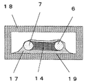
次に図6に示すように、少なくとも上記フラックス17を塗布した部分をケース18内に収納するように、ケース18の開口からフラックス17部分を挿入する。この時ケース18は、有底の箱状であり、断面は方形状,円形状などを適宜選択できる。
【0038】
次に図7に示すようにフラックス17部分をケース18内において所定の位置に配置されるように、ケース18を変位させ、ある程度設計上における所定の位置にフラックス17部分が位置したことを直接的或いは間接的に認識したら、ケース18及びリード線1aの少なくとも一方を固定した状態でケース18の表面部を加熱しケース18の内面19と接触しているフラックス17の表面部を軟化溶融させ、その後冷風等によりケース18を冷却し、フラックス17を固体に戻し、ケース18の内面19にフラックス17を接着させ、ケース18と可溶合金14,リード線1aを固定させる。
【0039】
このときケース加熱条件はフラックス17の軟化点温度から軟化点温度より、0℃〜50℃高い温度(好ましくは3℃〜30℃高い温度)の温度範囲で0.8秒〜4秒(好ましくは1〜2秒)の加熱時間範囲が最も確実な固定を行うことができた。このようにケース18,可溶合金14,リード線1aを相互に固定できる為、固定治具無しで図8に示すように封止できるようになり、連続生産が可能となった。
【0040】
次に図8に示すように上記固定されたケース18の開口部にディスペンサ20等のノズル21よりエポキシ、シリコン等の2液混合タイプの硬化性樹脂等の封止材22を吐出させ封止する。
【0041】
その後封止材23を常温またはフラックス17の軟化点より低い温度で一次硬化させ、つぎに温度ヒューズの動作温度より5℃〜40℃低い温度で(好ましくは10℃〜30℃低い温度)図9のようにケース18を上の状態で封止材23を本硬化させる。130℃の動作温度の温度ヒューズの場合100℃から120℃で本硬化させる。このとき封止材23は完全に硬化し内部のフラックスは軟化点を超える為、一部がケース内封止材23上に流れ落ちる。
【0042】
次に図10のようにリード線1aの底部3もしくはリード部4,5を切断する。リード部4,5を切断する場合には、リード部4,5の底部3近傍を切断することが好ましい。切断するときに両方のリード部4,5を同時に切断するため、両方のリード部4,5の同一方向にリード部4,5のそり、切断バリ等が発生するが、このことにより温度ヒューズをプリント基板上に実装する際にスルーホールに挿入し易いという効果も得られる。すなわち、底部3を切り離した部分であるリード部切断部26,27は、同一方向にバリなどが発生するので、プリント基板などに設けられたスルーホールなどに容易に挿入させやすい。従来の技術の様に、ばらばらの方向に切断部分のバリが発生すると、非常にプリント基板への実装が悪いことに着目し、上記の様にリード部切断部のバリの方向を揃えることで、プリント基板への挿入性を向上させた。
【0043】
次に搬送用フープ材9から温度ヒューズを抜取り図11のように完成品となる。また図10のように底部3を切断した状態でテーピング品として提供することも出来る。
【0044】
なお、本実施の形態では、一つの温度ヒューズの製造方法について説明したが、実際は搬送フープ材9にリード線1aが多数であって、しかも同一方向を向くように取り付けられており、この様に構成することで量産性が非常に良くなる。
【0045】
【発明の効果】
本発明は、底部と、底部の両端から同一方向に折り曲げられたリード部と、リード部において底部側と反対側の先端に設けられた先端部とを有したリード線を形成し、先端部間に可溶合金を溶接した後、底部もしくはリード部を切断したことで、可溶合金と先端部の熔着部から離れた位置で、リード部を切り離しているので、熔着部に応力やクラックが入るのを防止でき、製品の歩留まりを向上できる。更には、長期間の使用によって、前述の応力やクラックなどに起因する特性の劣化などを防止できる。
【図面の簡単な説明】
【図1】本発明の一実施の形態における温度ヒューズに用いられるリード線材を示す斜視図
【図2】本発明の一実施の形態における温度ヒューズの製造工程を示す斜視図
【図3】本発明の一実施の形態における温度ヒューズの製造工程を示す斜視図
【図4】本発明の一実施の形態における温度ヒューズの製造工程を示す斜視図
【図5】本発明の一実施の形態における温度ヒューズの製造工程を示す斜視図
【図6】本発明の一実施の形態における温度ヒューズの製造工程を示す斜視図
【図7】本発明の一実施の形態における温度ヒューズの製造工程を示す斜視図
【図8】本発明の一実施の形態における温度ヒューズの製造工程を示す斜視図
【図9】本発明の一実施の形態における温度ヒューズの製造工程を示す斜視図
【図10】本発明の一実施の形態における温度ヒューズの製造工程を示す斜視図
【図11】本発明の一実施の形態における温度ヒューズを示す斜視図
【図12】従来の温度ヒューズの製造方法を示す斜視図
【符号の説明】
1 リード線材
1a リード線
2 ボビン
3 底部
4,5 リード部
6,7 先端部
8 折り曲げ部
9 搬送フープ材
10,11 粘着テープ
12,13 貫通孔
14 可溶合金
15,16 溶着部
17 フラックス
18 ケース
19 ケース内面
20 ディスペンサ
21 ノズル
22,23 封止材
24,25 リード線切断部[0001]
BACKGROUND OF THE INVENTION
The present invention relates to a method of manufacturing a thermal fuse that is suitably used for preventing damage or the like of electronic equipment due to abnormal heating or the like, and uses a fusible alloy as a fuse element.
[0002]
[Prior art]
As shown in FIG. 12A, a conventional method for manufacturing a thermal fuse cuts a
[0003]
[Problems to be solved by the invention]
In the conventional configuration, since the vicinity of the welded portion of the
[0004]
Furthermore, the
[0005]
In addition, since the
[0006]
Furthermore, when the
[0007]
SUMMARY OF THE INVENTION The present invention solves the above-described conventional problems, and an object of the present invention is to provide a thermal fuse that improves insertability into a printed circuit board.
[0008]
It is an object of the present invention to provide a method for manufacturing a thermal fuse that can be reduced in size, particularly reduced in thickness.
[0009]
It is an object of the present invention to provide a method for manufacturing a thermal fuse for the purpose of improving yield in manufacturing.
[0010]
An object of this invention is to provide the manufacturing method of the thermal fuse which can acquire a desired characteristic even if it uses it for a long period of time.
[0011]
[Means for Solving the Problems]
The present invention forms a lead wire having a bottom portion, a lead portion bent in the same direction from both ends of the bottom portion, and a tip portion provided at the tip of the lead portion on the opposite side to the bottom portion side. After welding the fusible alloy, the bottom portion or the lead portion near the bottom portion was cut.
[0012]
DETAILED DESCRIPTION OF THE INVENTION
[0015]
The invention according to
[0016]
According to a second aspect of the invention, by placing the fusible alloy between opposing portions facing each other at the distal end, the thermal fuse of
[0017]
According to a third aspect of the invention, after applying the first flux at least part of the distal end portion, the temperature fuse according to
[0018]
The invention of
[0019]
According to a fifth aspect of the present invention, a box-shaped case having an opening at one end is separately prepared, the second flux application part and a part of the lead wire are accommodated in the case, and the second flux is subjected to heat treatment. 5. The method of manufacturing a thermal fuse according to
[0020]
According to a sixth aspect of the present invention, there is provided a method for manufacturing a thermal fuse according to the fifth aspect, wherein a sealing material is provided in the case opening, and the inside of the case where the second flux application part is disposed and the outside are blocked. Thus, when the fusible alloy comes into contact with the outside air, it is possible to prevent the deterioration of characteristics, and it is possible to prevent the deterioration of the fusing characteristics due to moisture.
[0021]
The invention of
[0022]
Invention of
[0023]
Invention of
[0024]
DESCRIPTION OF THE PREFERRED EMBODIMENTS Embodiments of the present invention will be described below with reference to the drawings, showing the manufacturing process and the configuration thereof.
[0025]
First, the
[0026]
At this time, the lead wire 1a is provided at the respective ends of the linear or arc-shaped
[0027]
The
[0028]
As shown in FIG. 2, the lead wire 1a has the
[0029]
In the present embodiment, when the lead wire 1a is fixed to the
[0030]
Next, as shown in FIG. 3, when the
[0031]
At this time, when expanding the
[0032]
Further, when the
[0033]
However, according to the present embodiment, by disposing the facing surfaces 6b and 7b and the
[0034]
The
[0035]
Next, the
[0036]
Next, as shown in FIG. 5, the
[0037]
Next, as shown in FIG. 6, the
[0038]
Next, as shown in FIG. 7, the
[0039]
At this time, the case heating conditions are 0.8 second to 4 seconds (preferably in a temperature range of 0 ° C. to 50 ° C. higher than the softening point temperature of the flux 17 (preferably 3 ° C. to 30 ° C. higher). The most reliable fixing was possible within a heating time range of 1 to 2 seconds. Since the
[0040]
Next, as shown in FIG. 8, sealing is performed by discharging a sealing
[0041]
Thereafter, the sealing
[0042]
Next, as shown in FIG. 10, the
[0043]
Next, the thermal fuse is extracted from the conveying
[0044]
In the present embodiment, a method for manufacturing one thermal fuse has been described. Actually, however, a large number of lead wires 1a are attached to the conveying
[0045]
【The invention's effect】
The present invention forms a lead wire having a bottom portion, a lead portion bent in the same direction from both ends of the bottom portion, and a tip portion provided at the tip of the lead portion on the opposite side to the bottom portion side. After the fusible alloy is welded to the lead part, the bottom part or the lead part is cut, so that the lead part is cut away from the fusible alloy and the welded part of the tip part. Can be prevented, and the yield of products can be improved. Furthermore, deterioration of characteristics due to the above-described stress and cracks can be prevented by long-term use.
[Brief description of the drawings]
FIG. 1 is a perspective view showing a lead wire used for a thermal fuse in one embodiment of the present invention. FIG. 2 is a perspective view showing a manufacturing process of the thermal fuse in one embodiment of the present invention. FIG. 4 is a perspective view showing a manufacturing process of a thermal fuse in one embodiment of the present invention. FIG. 5 is a perspective view showing a manufacturing process of the thermal fuse in one embodiment of the present invention. FIG. 6 is a perspective view showing the manufacturing process of the thermal fuse in one embodiment of the present invention. FIG. 7 is a perspective view showing the manufacturing process of the thermal fuse in one embodiment of the present invention. FIG. 8 is a perspective view showing a manufacturing process of a thermal fuse in an embodiment of the present invention. FIG. 9 is a perspective view showing a manufacturing process of a thermal fuse in an embodiment of the present invention. Perspective view showing a perspective view and FIG. 12 conventional method of manufacturing a thermal fuse showing a thermal fuse in one embodiment of a perspective view showing a manufacturing process of the thermal fuse 11 of the present invention in the form [Description of symbols]
DESCRIPTION OF
Claims (9)
Priority Applications (1)
| Application Number | Priority Date | Filing Date | Title |
|---|---|---|---|
| JP2001170917A JP4752139B2 (en) | 2001-06-06 | 2001-06-06 | Manufacturing method of thermal fuse |
Applications Claiming Priority (1)
| Application Number | Priority Date | Filing Date | Title |
|---|---|---|---|
| JP2001170917A JP4752139B2 (en) | 2001-06-06 | 2001-06-06 | Manufacturing method of thermal fuse |
Publications (2)
| Publication Number | Publication Date |
|---|---|
| JP2002367497A JP2002367497A (en) | 2002-12-20 |
| JP4752139B2 true JP4752139B2 (en) | 2011-08-17 |
Family
ID=19012767
Family Applications (1)
| Application Number | Title | Priority Date | Filing Date |
|---|---|---|---|
| JP2001170917A Expired - Lifetime JP4752139B2 (en) | 2001-06-06 | 2001-06-06 | Manufacturing method of thermal fuse |
Country Status (1)
| Country | Link |
|---|---|
| JP (1) | JP4752139B2 (en) |
Families Citing this family (3)
| Publication number | Priority date | Publication date | Assignee | Title |
|---|---|---|---|---|
| CN100376704C (en) * | 2003-05-29 | 2008-03-26 | 松下电器产业株式会社 | Temperature fuse element, temperature fuse and battery using the same |
| KR100658809B1 (en) | 2004-12-06 | 2006-12-15 | 주식회사 알파이 | Method of producing fuses |
| JP2009540522A (en) * | 2006-06-16 | 2009-11-19 | スマート エレクトロニクス インク | Surface mount type small fuse and manufacturing method thereof |
Family Cites Families (5)
| Publication number | Priority date | Publication date | Assignee | Title |
|---|---|---|---|---|
| JPS58184219A (en) * | 1982-04-21 | 1983-10-27 | 日本電気ホームエレクトロニクス株式会社 | Method of producing temperature fuse |
| JPS62100655A (en) * | 1985-10-28 | 1987-05-11 | Hitachi Plant Eng & Constr Co Ltd | Analyzer for copper etching liquid |
| JPH01106051A (en) * | 1987-10-20 | 1989-04-24 | Fuji Photo Film Co Ltd | Photographic element for color diffusion transfer process |
| JPH07116594B2 (en) * | 1989-07-31 | 1995-12-13 | 日本電気株式会社 | Electron gun type film forming equipment |
| JPH071669B2 (en) * | 1992-03-25 | 1995-01-11 | 協伸工業株式会社 | Fuse clip mounting method and fuse clip combination |
-
2001
- 2001-06-06 JP JP2001170917A patent/JP4752139B2/en not_active Expired - Lifetime
Also Published As
| Publication number | Publication date |
|---|---|
| JP2002367497A (en) | 2002-12-20 |
Similar Documents
| Publication | Publication Date | Title |
|---|---|---|
| US7411478B2 (en) | Coil component | |
| US7471179B2 (en) | Coil component | |
| US11024459B2 (en) | Method of manufacturing coil component | |
| JP3562696B2 (en) | Manufacturing method of fuse element | |
| US10116053B2 (en) | Antenna coil component, antenna unit, and method of manufacturing the antenna coil component | |
| US8305181B2 (en) | Chip inductor and manufacturing method thereof | |
| JP6884603B2 (en) | Coil parts | |
| US10454235B2 (en) | Method of manufacturing coil component | |
| WO2019004038A1 (en) | Inductor component and method for manufacturing same | |
| KR950014122B1 (en) | Tape carriar package and high frequency heating softbond device | |
| CN105789074A (en) | Method for manufacturing semiconductor device | |
| JP4752139B2 (en) | Manufacturing method of thermal fuse | |
| KR20120015277A (en) | Flex film contacting and method for producing the same | |
| JP5828995B2 (en) | Method of laser welding without filler material and electrical device formed by the method | |
| JPH0950830A (en) | Junction structure of terminal and lead wire, and junction method for terminal and lead wire | |
| JP6817509B2 (en) | Inductor parts and their manufacturing methods | |
| JP2000164093A (en) | Thermal fuse and its manufacture | |
| JP6890222B2 (en) | Inductor parts | |
| JP2003022738A (en) | Manufacturing method of thermal fuse | |
| JP2005165200A (en) | Optical device and its manufacturing method | |
| JP4651135B2 (en) | Coil parts | |
| JP3751080B2 (en) | Electronic components | |
| JP2023074359A (en) | Stem for semiconductor package | |
| JPH05152129A (en) | Manufacture of chip-shaped coil | |
| JPS6245657B2 (en) |
Legal Events
| Date | Code | Title | Description |
|---|---|---|---|
| A621 | Written request for application examination |
Free format text: JAPANESE INTERMEDIATE CODE: A621 Effective date: 20080606 |
|
| RD01 | Notification of change of attorney |
Free format text: JAPANESE INTERMEDIATE CODE: A7421 Effective date: 20080714 |
|
| RD01 | Notification of change of attorney |
Free format text: JAPANESE INTERMEDIATE CODE: A7421 Effective date: 20091119 |
|
| A977 | Report on retrieval |
Free format text: JAPANESE INTERMEDIATE CODE: A971007 Effective date: 20110105 |
|
| A131 | Notification of reasons for refusal |
Free format text: JAPANESE INTERMEDIATE CODE: A131 Effective date: 20110201 |
|
| A521 | Written amendment |
Free format text: JAPANESE INTERMEDIATE CODE: A523 Effective date: 20110404 |
|
| TRDD | Decision of grant or rejection written | ||
| A01 | Written decision to grant a patent or to grant a registration (utility model) |
Free format text: JAPANESE INTERMEDIATE CODE: A01 Effective date: 20110426 |
|
| A61 | First payment of annual fees (during grant procedure) |
Free format text: JAPANESE INTERMEDIATE CODE: A61 Effective date: 20110509 |
|
| FPAY | Renewal fee payment (event date is renewal date of database) |
Free format text: PAYMENT UNTIL: 20140603 Year of fee payment: 3 |
|
| R151 | Written notification of patent or utility model registration |
Ref document number: 4752139 Country of ref document: JP Free format text: JAPANESE INTERMEDIATE CODE: R151 |
|
| FPAY | Renewal fee payment (event date is renewal date of database) |
Free format text: PAYMENT UNTIL: 20140603 Year of fee payment: 3 |
|
| EXPY | Cancellation because of completion of term |


