JP4745682B2 - CO2 recovery apparatus and method - Google Patents
CO2 recovery apparatus and method Download PDFInfo
- Publication number
- JP4745682B2 JP4745682B2 JP2005047857A JP2005047857A JP4745682B2 JP 4745682 B2 JP4745682 B2 JP 4745682B2 JP 2005047857 A JP2005047857 A JP 2005047857A JP 2005047857 A JP2005047857 A JP 2005047857A JP 4745682 B2 JP4745682 B2 JP 4745682B2
- Authority
- JP
- Japan
- Prior art keywords
- solution
- regeneration tower
- semi
- lean
- exhaust gas
- Prior art date
- Legal status (The legal status is an assumption and is not a legal conclusion. Google has not performed a legal analysis and makes no representation as to the accuracy of the status listed.)
- Expired - Fee Related
Links
Images


Classifications
-
- B—PERFORMING OPERATIONS; TRANSPORTING
- B01—PHYSICAL OR CHEMICAL PROCESSES OR APPARATUS IN GENERAL
- B01D—SEPARATION
- B01D53/00—Separation of gases or vapours; Recovering vapours of volatile solvents from gases; Chemical or biological purification of waste gases, e.g. engine exhaust gases, smoke, fumes, flue gases, aerosols
- B01D53/14—Separation of gases or vapours; Recovering vapours of volatile solvents from gases; Chemical or biological purification of waste gases, e.g. engine exhaust gases, smoke, fumes, flue gases, aerosols by absorption
- B01D53/1425—Regeneration of liquid absorbents
-
- B—PERFORMING OPERATIONS; TRANSPORTING
- B01—PHYSICAL OR CHEMICAL PROCESSES OR APPARATUS IN GENERAL
- B01D—SEPARATION
- B01D53/00—Separation of gases or vapours; Recovering vapours of volatile solvents from gases; Chemical or biological purification of waste gases, e.g. engine exhaust gases, smoke, fumes, flue gases, aerosols
- B01D53/14—Separation of gases or vapours; Recovering vapours of volatile solvents from gases; Chemical or biological purification of waste gases, e.g. engine exhaust gases, smoke, fumes, flue gases, aerosols by absorption
- B01D53/1456—Removing acid components
- B01D53/1475—Removing carbon dioxide
-
- F—MECHANICAL ENGINEERING; LIGHTING; HEATING; WEAPONS; BLASTING
- F23—COMBUSTION APPARATUS; COMBUSTION PROCESSES
- F23J—REMOVAL OR TREATMENT OF COMBUSTION PRODUCTS OR COMBUSTION RESIDUES; FLUES
- F23J2219/00—Treatment devices
- F23J2219/40—Sorption with wet devices, e.g. scrubbers
-
- F—MECHANICAL ENGINEERING; LIGHTING; HEATING; WEAPONS; BLASTING
- F23—COMBUSTION APPARATUS; COMBUSTION PROCESSES
- F23J—REMOVAL OR TREATMENT OF COMBUSTION PRODUCTS OR COMBUSTION RESIDUES; FLUES
- F23J2219/00—Treatment devices
- F23J2219/80—Quenching
-
- Y—GENERAL TAGGING OF NEW TECHNOLOGICAL DEVELOPMENTS; GENERAL TAGGING OF CROSS-SECTIONAL TECHNOLOGIES SPANNING OVER SEVERAL SECTIONS OF THE IPC; TECHNICAL SUBJECTS COVERED BY FORMER USPC CROSS-REFERENCE ART COLLECTIONS [XRACs] AND DIGESTS
- Y02—TECHNOLOGIES OR APPLICATIONS FOR MITIGATION OR ADAPTATION AGAINST CLIMATE CHANGE
- Y02C—CAPTURE, STORAGE, SEQUESTRATION OR DISPOSAL OF GREENHOUSE GASES [GHG]
- Y02C20/00—Capture or disposal of greenhouse gases
- Y02C20/40—Capture or disposal of greenhouse gases of CO2
Description
本発明は、燃焼排ガスなどのCO2 含有ガス中に含まれるCO2 を除去、回収するに好適なCO2回収装置および方法に関し、さらに詳しくは、エネルギ効率の改善されたCO2 含有ガス中のCO2を除去、回収するCO2回収装置および方法に関するものである。 The present invention relates to a CO 2 recovery apparatus and method suitable for removing and recovering CO 2 contained in a CO 2 -containing gas such as combustion exhaust gas, and more particularly, in a CO 2 -containing gas with improved energy efficiency. CO 2 is removed, to a CO 2 recovery apparatus and method for recovering.
近年、地球の温暖化現象の原因の一つとして、CO2 による温室効果が指摘され、地球環境を守る上で国際的にもその対策が急務となってきた。CO2 の発生源としては化石燃料を燃焼させるあらゆる人間の活動分野に及び、その排出抑制への要求が一層強まる傾向にある。これに伴い大量の化石燃料を使用する火力発電所などの動力発生設備を対象に、ボイラやガスタービン等、産業設備の燃焼排ガスをアミン系CO2 吸収液と接触させ、燃焼排ガス中のCO2 を除去、回収する方法および回収されたCO2を大気へ放出することなく貯蔵する方法が精力的に研究されている。また前記のようなCO2 吸収液を用い、燃焼排ガスからCO2 を除去・回収する工程としては、吸収塔において燃焼排ガスとCO2 吸収液とを接触させる工程、CO2 を吸収したCO2吸収液を再生塔において加熱し、CO2 を遊離させるとともにCO2吸収液を再生して再び吸収塔に循環して再使用するものが採用されている(例えば、特許文献1を参照)。 In recent years, the greenhouse effect due to CO 2 has been pointed out as one of the causes of global warming, and countermeasures have become urgent internationally to protect the global environment. The source of CO 2 extends to all human activity fields that burn fossil fuels, and there is a tendency for the demand for emission control to become stronger. Along with this, for the power generation facilities such as thermal power plants that use a large amount of fossil fuel, the combustion exhaust gas of industrial equipment such as boilers and gas turbines is brought into contact with the amine-based CO 2 absorbent, and the CO 2 in the combustion exhaust gas A method for removing and recovering CO 2 and a method for storing the recovered CO 2 without releasing it to the atmosphere have been energetically studied. The use of a CO 2 absorbing solution as described above, as the process of removing and recovering CO 2 from combustion exhaust gas, the absorbed CO 2 absorption step of contacting the combustion exhaust gas and the CO 2 absorbing solution in an absorption tower, the CO 2 A solution is used in which the liquid is heated in a regeneration tower to liberate CO 2 and the CO 2 absorbent is regenerated and recycled to the absorption tower for reuse (for example, see Patent Document 1).
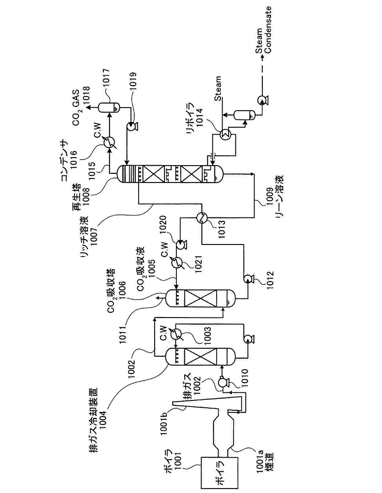
前記従来のCO2回収装置は、図7に示すように、ボイラやガスタービン等、産業設備1001から排出されたCO2を含有する排出ガス1002を冷却水1003によって冷却する排ガス冷却装置1004と、冷却されたCO2を含有する排ガス1002とCO2を吸収するCO2吸収液1005とを接触させて前記排ガス1002からCO2を除去するCO2吸収塔1006と、CO2を吸収したCO2吸収液(リッチ溶液)1007からCO2を放出させてCO2吸収液を再生する再生塔1008とを有する。この装置では、前記再生塔1008でCO2を除去した再生CO2吸収液(リーン溶液)1009は前記吸収塔1006でCO2吸収液として再利用する。
As shown in FIG. 7, the conventional CO 2 recovery device includes an exhaust
この従来のCO2回収装置を用いたCO2回収方法では、まず、CO2を含んだボイラやガスタービン等、産業設備燃焼排ガス1002は、排ガス送風機1010により昇圧された後、排ガス冷却装置1004に送られ、ここで冷却水1003により冷却され、CO2吸収塔1006に送られる。
In the CO 2 recovery method using this conventional CO 2 recovery device, first, the industrial facility
前記CO2吸収塔1006において、排ガス1002はアルカノールアミンをベースとするCO2吸収液1005と交向流接触し、排ガス1002中のCO2は、化学反応(R−NH2+H2O+CO2→R−NH3HCO3)によりCO2吸収液1005に吸収され、CO2が除去された排ガス1011は系外に放出される。CO2を吸収したCO2吸収液1007はリッチ溶液とも呼称される。このリッチ溶液1007はリッチソルベントポンプ1012により昇圧され、リッチ/リーンソルベント熱交換器1013において、後述の再生塔1008でCO2を除去されることにより再生されたCO2吸収液(リーン溶液)1009により加熱され、再生塔1008に供給される。
In the CO 2 absorption tower 1006, the
再生塔1008の上部から再生塔1008内部に放出されたリッチ溶液1007は、発熱反応を生じて、大部分のCO2を放出する。再生塔1008内で一部または大部分のCO2を放出したCO2吸収液はセミリーン溶液と呼称される。このセミリーン溶液は、再生塔1008下部に至る頃には、ほぼ全てのCO2が除去されたCO2吸収液となる。このほぼ全てのCO2が除去されることにより再生された吸収液はリーン溶液と呼称される。このリーン溶液はリボイラ1014でスチームにより加熱される。一方、再生塔1008の頭頂部からは塔内においてリッチ溶液およびセミリーン溶液から放出された水蒸気を伴ったCO2ガス1015が導出され、オーバーヘッドコンデンサ1016により水蒸気が凝縮され、分離ドラム1017にて水が分離され、CO2ガス1018が系外に放出されて回収される。分離ドラム1017にて分離された水は凝縮水循環ポンプ1019にて再生塔1008の上部に供給される。再生されたCO2吸収液(リーン溶液)1009は、前記リッチ/リーンソルベント熱交換器1013にて前記リッチ溶液1007により冷却され、つづいてリーンソルベントポンプ1020にて昇圧され、さらにリーンソルベントクーラ1021にて冷却された後、CO2吸収塔1006に供給される。
The
なお、図7中、符号1001aはボイラやガスタービン等、産業設備1001の煙道であり、100bは煙突である。前記CO2回収装置は、既設の排ガス源からCO2を回収するために後付で設けられる場合と、新設排ガス源に同時付設される場合とがある。煙突1001bには開閉可能な扉を設置し、CO2回収装置の運転時は閉止する。また排ガス源は稼動しているが、CO2回収装置の運転を停止した際は開放するように設定する。
In addition, in FIG. 7, the code |
前記CO2吸収液およびCO2吸収工程を用いて、燃焼排ガスのようなCO2含有ガスからCO2を回収する方法においては、そのCO2回収装置を燃焼設備に付加的に設置する構成となっているため、CO2回収装置そのものの操業費用も可能な限り低減させる必要がある。特に、前記CO2回収方法において、再生塔を用いた再生工程は多量の熱エネルギーを消費するので、この再生工程における消費エネルギーの削減を可能とするプロセスを開発することが重要である。 In the method of recovering CO 2 from a CO 2 -containing gas such as combustion exhaust gas using the CO 2 absorbing liquid and the CO 2 absorbing step, the CO 2 recovery device is additionally installed in the combustion facility. Therefore, it is necessary to reduce the operating cost of the CO 2 recovery device itself as much as possible. In particular, in the CO 2 recovery method, a regeneration process using a regeneration tower consumes a large amount of heat energy, and therefore it is important to develop a process that can reduce energy consumption in the regeneration process.
本発明は、上記事情に鑑みてなされたものであって、エネルギー効率をさらに向上させたCO2回収装置および回収方法を提供することを課題とする。 The present invention was made in view of the above circumstances, and an object thereof is to provide a further CO 2 recovery apparatus and recovery method with improved energy efficiency.
前記課題を解決するための本発明の第1の発明は、産業設備から排出されたCO2を含有する排ガスとCO2を吸収するCO2吸収液とを接触させて前記排ガスからCO2を除去するCO2吸収塔と、CO2を吸収したCO2吸収液であるリッチ溶液からCO2を除去することにより前記リッチ溶液をCO2の吸収のないCO2吸収液であるリーン溶液に再生する再生塔とを有し、前記再生塔でCO2が除去されてなるリーン溶液を前記CO2吸収液として前記吸収塔で再利用するCO2回収装置において、前記再生塔の上部から前記再生塔内に注入されたリッチ溶液から一部のCO2が放出されてなるセミリーン溶液の少なくとも一部を該再生塔から抜き出し、前記ボイラ等の産業設備煙道内の高温の排ガスと熱交換させて昇温した後、該再生塔内に戻すセミリーン溶液抜き出し昇温返還流路を設けたことを特徴とするCO2回収装置にある。なお、本発明において、産業設備とは、例えば、ボイラ、ガスタービンなどの燃焼を伴う設備を意味する。 The first invention of the present invention for solving the above problems, the removal of CO 2 from the flue gas by contacting the CO 2 absorbing liquid to absorb the exhaust gas and CO 2 containing CO 2 discharged from industrial facilities and CO 2 absorption tower for reproduction to reproduce the lean solution the a CO 2 absorbing solution with no absorption of the rich solution of CO 2 by removing CO 2 from the rich solution is CO 2 absorbent having absorbed CO 2 A CO 2 recovery apparatus for reusing a lean solution from which CO 2 has been removed in the regeneration tower as the CO 2 absorbing liquid in the absorption tower, from above the regeneration tower into the regeneration tower. After at least a part of the semi-lean solution in which a part of CO 2 is released from the injected rich solution is extracted from the regeneration tower, and heat-exchanged with high-temperature exhaust gas in an industrial equipment flue such as the boiler, and then the temperature is raised. In the regeneration tower The CO 2 recovery apparatus is characterized in that a semi-lean solution to be returned is withdrawn and a temperature raising return reflux path is provided. In addition, in this invention, an industrial installation means the installation accompanying combustion, such as a boiler and a gas turbine, for example.
第2の発明は、第1の発明において、前記セミリーン溶液抜き出し昇温返還流路の前記再生塔への返還位置を前記再生塔の前記セミリーン溶液抜き出し位置より下方に設定したことを特徴とする記載のCO2回収装置にある。 The second invention is characterized in that, in the first invention, the return position of the semi-lean solution extraction temperature rising return reflux path to the regeneration tower is set below the semi-lean solution extraction position of the regeneration tower. In the CO 2 recovery unit.
第3の発明は、第1または2の発明において、前記再生塔における前記セミリーン溶液の抜き出し位置が前記リッチ溶液の注入位置近傍から該再生塔の中段までの間の任意の位置であることを特徴とするCO2回収装置にある。 A third invention is characterized in that, in the first or second invention, the extraction position of the semi-lean solution in the regeneration tower is an arbitrary position between the vicinity of the rich solution injection position and the middle stage of the regeneration tower. In the CO 2 recovery unit.
第4の発明は、第1〜3のいずれかの発明において、前記再生塔における前記セミリーン溶液の抜き出し位置が複数であり、これら複数の抜き出しセミリーン溶液の前記排ガスとの熱交換後の前記再生塔への返還位置が一カ所もしくは前記抜き出し位置の数以下の複数箇所であることを特徴とするCO2回収装置にある。 According to a fourth invention, in any one of the first to third inventions, there are a plurality of extraction positions of the semi-lean solution in the regeneration tower, and the regeneration tower after heat exchange of the plurality of extracted semi-lean solutions with the exhaust gas is performed. The CO 2 recovery apparatus is characterized in that there are one return position or a plurality of return positions equal to or less than the number of the extraction positions.
第5の発明は、煙道から抜き出した燃焼排ガスとCO2吸収液とを接触させてCO2をCO2吸収液に吸収するCO2吸収塔と、前記CO2吸収液を加熱してCO2をCO2吸収液から除去する再生塔と、煙道に設けられた排ガス熱交換部と、CO2吸収液を前記再生塔から抜き出して前記排ガス熱交換部に移送する抜き出しセミリーン往路管と、CO2吸収液を前記排ガス熱交換部から前記再生塔に移送する前記抜き出しセミリーン復路管と、を備え、CO2を吸収したCO2吸収液であるリッチ溶液からCO2を除去してリーン溶液とする際、前記排ガス熱交換部において燃焼排ガスとCO2吸収液と熱交換して燃焼排ガスの熱を利用するCO2回収装置にある。 A fifth invention is a CO 2 absorption tower for absorbing CO 2 in CO 2 absorbing solution by contacting the extracted from the flue flue gas and the CO 2 absorbing solution, and heating the CO 2 absorbing solution CO 2 A regenerator for removing CO 2 from the CO 2 absorbent, an exhaust gas heat exchange section provided in the flue, an extraction semi-lean forward pipe for extracting the CO 2 absorbent from the regeneration tower and transferring it to the exhaust gas heat exchange section, CO with 2 and absorbing liquid the extracted semi-lean solution return pipe to transfer to the regeneration tower from the exhaust gas heat exchange section, and the lean solution to remove the CO 2 from the rich solution is CO 2 absorbent having absorbed CO 2 In this case, the exhaust gas heat exchanging unit is in a CO 2 recovery device that uses the heat of the combustion exhaust gas by exchanging heat with the combustion exhaust gas and the CO 2 absorbent.
第6の発明は、産業設備から排出されたCO2を含有する排ガスとCO2を吸収するCO2吸収液とをCO2吸収塔内で接触させて前記排ガスからCO2を除去した後、前記CO2を吸収したCO2吸収液であるリッチ溶液を再生塔内に導入して該リッチ溶液からCO2を除去することにより前記リッチ溶液をCO2の吸収のないCO2吸収液であるリーン溶液に再生し、該リーン溶液を前記CO2吸収液として前記吸収塔で再利用するCO2回収方法において、前記再生塔の上部から該再生塔内に注入されたリッチ溶液から一部もしくは大部分のCO2が放出されてなるセミリーン溶液の少なくとも一部を該再生塔から抜き出し、前記ボイラやガスタービン等、産業設備の煙道内の高温の排ガスと熱交換させて昇温した後、該再生塔の前記セミリーン溶液抜き出し位置より下方の位置から該再生塔内に戻すことを特徴とするCO2回収方法にある。 A sixth invention is, after removal of CO 2 from the exhaust gas and the CO 2 absorbing liquid to absorb the exhaust gas and CO 2 containing CO 2 discharged from industrial facilities by contacting with CO 2 absorption tower, wherein lean solution wherein a CO 2 absorbing solution with no absorption of the rich solution of CO 2 by the rich solution is CO 2 absorbent that has absorbed CO 2 is introduced into regeneration tower for removing CO 2 from the rich solution In the CO 2 recovery method in which the lean solution is reused in the absorption tower as the CO 2 absorbent, part or most of the rich solution injected into the regeneration tower from the top of the regeneration tower. At least a part of the semi-lean solution from which CO 2 has been released is withdrawn from the regeneration tower, heat-exchanged with high-temperature exhaust gas in the flue of an industrial facility such as the boiler or gas turbine, and then heated up. Semiry From the position below the solution withdrawn position to the CO 2 recovery method and returning to the regeneration the column.
第7の発明は、第6の発明において、前記再生塔における前記セミリーン溶液の抜き出しを前記リッチ溶液の注入位置近傍から該再生塔の中段までの間の任意の位置から行うことを特徴とするCO2回収方法にある。 According to a seventh aspect, in the sixth aspect, the semi-lean solution is extracted from the regeneration tower from any position between the vicinity of the rich solution injection position and the middle stage of the regeneration tower. 2 in the collection method.
第8の発明は、第6または7の発明において、前記再生塔における前記セミリーン溶液の抜き出しを複数箇所から行い、これら複数の抜き出しセミリーン溶液を前記排ガスと熱交換させた後、前記再生塔への返還を一カ所もしくは前記抜き出し位置の数以下の複数箇所にて行うことを特徴とするCO2回収方法にある。 According to an eighth invention, in the sixth or seventh invention, the semi-lean solution in the regeneration tower is extracted from a plurality of locations, and the plurality of extracted semi-lean solutions are subjected to heat exchange with the exhaust gas, In the CO 2 recovery method, the return is performed at one place or at a plurality of places equal to or less than the number of the extraction positions.
本発明の特徴は、再生塔の上部から該再生塔内に注入されたリッチ溶液から一部もしくは大部分のCO2が放出されてなるセミリーン溶液の少なくとも一部を該再生塔から抜き出し、抜き出したセミリーン溶液を前記ボイラやガスタービン等、産業設備の煙道内の高温排ガスと熱交換させて昇温した後、該再生塔の前記セミリーン溶液抜き出し位置より下方の位置から該再生塔内に戻すことによって、再生塔内の温度プロフィールを引き上げることある。すなわち、本発明のCO2回収装置および方法は、排ガスの余熱を有効利用して、再生塔内の温度を上昇させて再生効率を向上させており、それによって、CO2の回収システムにおいて、より一層の省エネルギー化を実現することができる。 A feature of the present invention is that at least a part of a semi-lean solution in which a part or most of CO 2 is released from a rich solution injected into the regeneration tower is extracted from the regeneration tower and extracted from the regeneration tower. After the temperature is increased by exchanging heat with the high-temperature exhaust gas in the flue of an industrial facility such as the boiler or gas turbine, the semi-lean solution is returned to the regeneration tower from a position below the semi-lean solution extraction position of the regeneration tower. Increase the temperature profile in the regeneration tower. That is, the CO 2 recovery apparatus and method of the present invention effectively uses the residual heat of the exhaust gas to raise the temperature in the regeneration tower and improve the regeneration efficiency, thereby further improving the CO 2 recovery system. Further energy saving can be realized.
以下に、本発明の実施例を図面に基づいて詳細に説明する。なお、この実施例によりこの発明が限定されるものではない。 Embodiments of the present invention will be described below in detail with reference to the drawings. Note that the present invention is not limited to the embodiments.
図1は、本発明にかかるCO2回収装置の実施例1の概略構成図である。図中、前記図7に示した装置と同一構成には同一符号を付して説明を簡略化する。 FIG. 1 is a schematic configuration diagram of Example 1 of a CO 2 recovery apparatus according to the present invention. In the figure, the same components as those shown in FIG.
本発明の特徴は、先に述べたように、再生塔1008の上部から該再生塔1008内に噴出されたリッチ溶液1007から一部もしくは大部分のCO2が放出されてなるセミリーン溶液の少なくとも一部を該再生塔1008から抜き出し、抜き出したセミリーン溶液をボイラやガスタービン等、産業設備1001の煙道1001a内の高温の排ガスと熱交換させて昇温させた後、該再生塔1008の前記セミリーン溶液抜き出し位置より下方の位置から該再生塔1008内に戻すことによって、再生塔内の温度プロフィールを引き上げることある。
As described above, the feature of the present invention is that at least one of the semi-lean solution in which a part or most of CO 2 is released from the
本実施例では、再生塔1008内の段数を13段として用いた。なお、図1および後述の図3,5においては、図の煩雑化を避けるために充填槽層を2段積層した状態に描いたが、実際には多段積層している。本実施例においては、セミリーン抜き出し管1のセミリーン抜き出し位置1aを6段目の下端位置に設定している。
In this embodiment, the number of stages in the
段数を13段にした再生塔1008の6段目をセミリーン抜きだし位置1aとして再生塔1008に取り付けられたセミリーン抜き出し管1は、セミリーンソルベントポンプ2を介して抜き出しセミリーン往路管3に連結されている。この抜き出しセミリーン往路管3は、ボイラやガスタービン等、産業設備1001の煙道1001a内に侵入した後、煙道1001a内の排ガス1002との接触面積を高めるために例えば螺旋状に形成されている。この排ガスとの接触面積を高めた部分がセミリーン/排ガス熱交換部4を構成している。前記往路管3はこのセミリーン/排ガス熱交換部4を経て煙道1001aの外に延出した後、抜き出しセミリーン復路管5となって再生塔1008に戻る。この抜き出しセミリーン復路管5の再生塔1008へ取り付け位置であるセミリーン返還位置5aは、本実施例では、7段目の上端に設定されている。
The
前記構成において、セミリーン抜き出し管1と、抜き出しセミリーン往路管3、熱交換部4、抜き出しセミリーン復路管5は、セミリーン抜き出し昇温返還流路6を構成している。
In the above-described configuration, the
本実施例では、6段目に設けたセミリーン抜き出し位置1aから再生塔1008内の6段目の上部に存在するセミリーン溶液を100%抜き出している。この抜き出しセミリーン溶液の温度は、104℃であり、セミリーン/排ガス熱交換部4を通過後のセミリーン溶液の温度は109℃に昇温され、その温度を維持したまま、再生塔1008内の7段目の上部に戻された。前記セミリーン溶液と排ガスとの熱交換によって、煙道1001a内の排ガス1002は、150℃から128℃に降温された。この降温により排ガス冷却装置1004において消費される冷却エネルギーが低減される。また、このセミリーン溶液の排ガスによる昇温によって、リボイラ1014の熱量は、熱交換をしない時の熱量14.87MMkcal/hrから、13.94MMkcal/hrに低減された。このリボイラ熱量減少率は、6.24%にもなる。
In this embodiment, 100% of the semi-lean solution existing at the upper part of the sixth stage in the
さらに、図2に示すように、109℃に昇温されたセミリーン溶液を再生塔1008の7段目に戻すことによって再生塔1008内の温度分布プロフィールが高温側に引き上げられる。図2において、実線が本実施例1による再生塔温度分布プロフィールであり、点線がセミリーン溶液の抜き出し昇温変換処理をしない従来の場合の再生塔内温度分布プロフィールである。6段目から100%のセミリーン溶液を抜き出し、排ガスにより109℃に昇温させた後、7段目に返還することによって、図示のように、4段目から11段目にかけて温度プロフィールが高温側にシフトする。この中段における温度分布の高温側へのシフトは、本発明特有の効果であり、従来のリボイラ1014による加熱では得ることができない。
Furthermore, as shown in FIG. 2, the temperature distribution profile in the
前記再生塔1008内の温度分布プロフィールの高温側へのシフトは、中段部分においてなされており、上段部分の温度は上昇していない。その結果、コンデンサ1016の消費熱量は、従来装置と本実施例装置とで、ほぼ同様の値となっている。
The temperature distribution profile in the
前述の各測定結果は、表1に一覧表示した。 The above-mentioned measurement results are listed in Table 1.
図3は、本発明にかかるCO2回収装置の第2の実施例の概略構成図である。図中、前記図1に示した装置と同一構成には同一符号を付して説明を簡略化する。この実施例2では、前記実施例1において、再生塔1008におけるセミリーン溶液の抜き出し位置1bを前記リッチ溶液1007の再生塔1008への注入位置(4段目)に設定するとともに、復路管5の再生塔1008への返還位置5bを6段目に設定したことと、セミリーン溶液の抜き出し量を50%に設定したことが異なる。
FIG. 3 is a schematic configuration diagram of a second embodiment of the CO 2 recovery apparatus according to the present invention. In the figure, the same components as those shown in FIG. In Example 2, the
本実施例2では、前述のように、リッチ溶液1007の注入位置である4段目に設けたセミリーン抜き出し位置1bから再生塔1008内の4段目に存在するセミリーン溶液を50%抜き出している。この抜き出しセミリーン溶液の温度は、103℃であり、セミリーン/排ガス熱交換部4を通過後のセミリーン溶液の温度は113℃に昇温され、その温度を維持したまま、再生塔1008内の6段目の上部に戻された。前記セミリーン溶液と排ガスとの熱交換によって、煙道1001a内の排ガス1002は、150℃から126℃に降温された。この降温により排ガス冷却装置1004において消費される冷却エネルギーが低減される。また、このセミリーン溶液の排ガスによる昇温によって、リボイラ1014の熱量は、熱交換をしない時の熱量14.87MMkcal/hrから、13.91MMkcal/hrに低減された。このリボイラ熱量減少率は、6.43%にもなる。
In Example 2, as described above, 50% of the semi-lean solution existing in the fourth stage in the
さらに、図4に示すように、113℃に昇温されたセミリーン溶液を再生塔1008の6段目に戻すことによって再生塔1008内の温度分布プロフィールが高温側に引き上げられる。図4において、実線が本実施例2による再生塔内の温度分布プロフィールであり、点線がセミリーン溶液の抜き出し昇温変換処理をしない従来の場合の再生塔内温度分布プロフィールである。4段目から50%のセミリーン溶液を抜き出し、排ガスにより113℃に昇温させた後、6段目に返還することによって、図示のように、主に4段目から11段目にかけて温度プロフィールが高温側にシフトする。この中段における温度分布の高温側へのシフトは、本発明特有の効果であり、従来のリボイラ1014による加熱では得ることができない。
Furthermore, as shown in FIG. 4, the temperature distribution profile in the
前記再生塔1008内の温度分布プロフィールの高温側へのシフトは、主に中段部分においてなされており、上段部分の温度上昇はごく僅かである。その結果、コンデンサ1016の消費熱量は、従来装置と本実施例装置とで、−4.14MMkcal/hrから−4.22MMkcal/hrに微増しただけで、ほぼ同様の値となっている。
The temperature distribution profile in the
前述の各測定結果は、表1に一覧表示した。 The above-mentioned measurement results are listed in Table 1.
図5は、本発明にかかるCO2回収装置の実施例3の概略構成図である。図中、前記図1および図3に示した装置と同一構成には同一符号を付して説明を簡略化する。この実施例3では、前記実施例1において、再生塔1008におけるセミリーン溶液の抜き出し位置を2箇所(位置11a、21a)に設定し、各セミリーン抜き出し昇温返還流路16,26の各復路管15,25を後半部分で一本の復路管35に合流させて一箇所の返還位置35bから再生塔1008に戻す点が異なる。
FIG. 5 is a schematic configuration diagram of Example 3 of the CO 2 recovery apparatus according to the present invention. In the figure, the same components as those shown in FIG. 1 and FIG. In this Example 3, the semi-lean solution extraction position in the
前記抜き出し位置11aは前記実施例2と同様に4段目であり、前記抜きだし位置21aは実施例1と同様に第6段目である。各往路管11,21は、煙道1001a内で螺旋形状に成形されてセミリーン/排ガス熱交換部14,24を構成し、その後、それぞれ前記復路管15,25に連結している。復路管15,25が後半合流されてなる前記復路管35の再生塔1008への取り付け位置である返還位置35aは7段目の上部に設定されている。
The
本実施例3では、再生塔1008内のセミリーン溶液を2箇所から抜き出す。一方の抜き出し位置11aは、前述のように、リッチ溶液1007の注入位置である4段目の上部に設定されている。このセミリーン抜き出し位置11aから再生塔1008内の4段目の槽充填層層上部に存在するセミリーン溶液を50%抜き出している。この抜き出しセミリーン溶液の温度は、102℃であり、セミリーン/排ガス熱交換部14を通過後のセミリーン溶液の温度は103℃に昇温され、その温度を維持したまま、復路管15に流される。
In Example 3, the semi-lean solution in the
他方の抜き出し位置21aは、前述のように、6段目の槽充填層層の上部に設定されている。このセミリーン抜き出し位置21aから再生塔1008内の6段目の槽充填層層上部に存在するセミリーン溶液を100%抜き出している。この抜き出しセミリーン溶液の温度は、104℃であり、セミリーン/排ガス熱交換部24を通過後のセミリーン溶液の温度は109℃に昇温され、その温度を維持したまま、復路管25に流される。
As described above, the other extraction position 21a is set on the upper part of the sixth tank filling layer. From this
前記復路管15,25を流れるセミリーン溶液はそれぞれ103℃、109℃に昇温されており、復路管35に合流され、再生塔1008内の7段目槽充填層層の上部に戻された。前記2種のセミリーン溶液と排ガスとの熱交換によって、煙道1001a内の排ガス1002は、セミリーン/排ガス熱交換部24を通過することによって、150℃から128℃に降温され、さらにセミリーン/排ガス熱交換部14を通過することによって、128℃から126℃に降温された。この降温により排ガス冷却装置1004において消費される冷却エネルギーが低減される。また、これらのセミリーン溶液の排ガスによる昇温によって、リボイラ1014の熱量は、熱交換をしない時の熱量14.87MMkcal/hrから、13.86MMkcal/hrに低減された。このリボイラ熱量減少率は、6.77%にもなる。
The semi-lean solutions flowing through the
さらに、図6に示すように、昇温されたセミリーン溶液を再生塔1008の7段目に戻すことによって再生塔1008内の温度分布プロフィールが高温側に引き上げられる。図6において、実線が本実施例3による再生塔温度分布プロフィールであり、点線がセミリーン溶液の抜き出し昇温変換処理をしない従来の場合の再生塔内温度分布プロフィールである。リッチ溶液の注入位置である4段目の槽充填層層上部から50%のセミリーン溶液を抜き出し、排ガスにより103℃に昇温させたセミリーン溶液と、6段目の充填層上部から抜き出し、排ガスにより109℃に昇温させたセミリーン溶液とを合流させた後、7段目に返還することによって、図示のように、主に4段目から11段目にかけて温度プロフィールが高温側にシフトしていることが確認された。この中段における温度分布プロフィールの高温側へのシフトは、本発明特有の効果であり、従来のリボイラ1014による加熱では得ることができない。
Furthermore, as shown in FIG. 6, the temperature distribution profile in the
前記再生塔1008内の温度分布プロフィールの高温側へのシフトは、主に中段部分においてなされており、上段部分の温度上昇はごく僅かである。その結果、コンデンサ1016の消費熱量は、従来装置と本実施例装置とで、−4.14MMkcal/hrから−4.18MMkcal/hrに微増しただけで、ほぼ同様の値となっている。
The temperature distribution profile in the
前述の各測定結果は、表1に一覧表示した。
なお、本実施例3では再生塔内のセミリーン溶液を2箇所から抜き出し、排ガスとの熱交換後、再生塔に一箇所にて返還しているが、排ガスとの熱交換後の2種のセミリーン溶液を合流させずに、別々に再生塔に返還しても良い。
The above-mentioned measurement results are listed in Table 1.
In Example 3, the semi-lean solution in the regeneration tower is extracted from two places, and after heat exchange with the exhaust gas, it is returned to the regeneration tower at one place. However, the two types of semi-lean after the heat exchange with the exhaust gas are returned. You may return to a regeneration tower separately, without making a solution merge.
前記各実施例から明らかなように、再生塔1008から少なくとも一部のセミリーン溶液を抜き出し、排ガス1002の余熱により昇温させて、再び、再生塔1008に戻すという本発明の構成によって、(i)排ガス冷却装置1004における冷却エネルギーを削減でき、(ii)再生塔1008内の中段の温度プロフィールを高温側に引き上げて再生効率を高めることができ、(iii)再生効率を維持するために再生塔1008底部を加熱しているリボイラ1014の消費熱量を低減することができる。
As is clear from each of the above embodiments, at least a part of the semi-lean solution is extracted from the
以上説明したように、本発明によれば、エネルギー効率をさらに向上させたCO2回収装置および回収方法を提供することができる。 As described above, according to the present invention, it is possible to provide a CO 2 recovery device and a recovery method with further improved energy efficiency.
1 セミリーン抜き出し管
1a,1b セミリーン抜き出し位置
2 セミリーンソルベントポンプ
3,11,21 抜き出しセミリーン往路管
4,14,24 セミリーン/排ガス熱交換部
5、15,25 抜き出しセミリーン復路管
5a,5b セミリーン返還位置
6,16,26 セミリーン抜き出し昇温返還流路
35 セミリーン合流復路管
1001 産業設備(ボイラやガスタービン等)
1001a 煙道
1002 排ガス
1004 排ガス冷却装置
1005 CO2吸収液
1006 CO2吸収塔
1007 リッチ溶液
1008 再生塔
1009 リーン溶液
1014 リボイラ
1016 オーバーヘッドコンデンサ
1
Claims (8)
前記再生塔の上部から前記再生塔内に注入されたリッチ溶液から一部のCO2が放出されてなるセミリーン溶液の少なくとも一部を該再生塔から抜き出し、前記ボイラ等の産業設備煙道内の高温の排ガスと熱交換させて昇温した後、該再生塔内に戻すセミリーン溶液抜き出し昇温返還流路を設けたことを特徴とするCO2回収装置。 And the CO 2 absorber to remove CO 2 from the flue gas by contacting the CO 2 absorbing liquid to absorb the exhaust gas and CO 2 containing CO 2 discharged from industrial facilities, CO 2 absorbent having absorbed CO 2 in it and a regenerator to regenerate lean solvent is CO 2 absorbing solution without the rich solution in absorption of CO 2 by removing CO 2 from the rich solution, and CO 2 is removed in the regenerator In the CO 2 recovery device for reusing the lean solution as the CO 2 absorbent in the absorption tower,
At least a part of the semi-lean solution in which a part of CO 2 is released from the rich solution injected into the regeneration tower from the upper part of the regeneration tower is extracted from the regeneration tower, and the high temperature in the industrial equipment flue such as the boiler is extracted. A CO 2 recovery device, comprising a semi-lean solution that is heated up by exchanging heat with the exhaust gas and then returned to the regeneration tower and is heated and returned.
前記CO2吸収液を加熱してCO2をCO2吸収液から除去する再生塔と、
煙道に設けられた排ガス熱交換部と、
CO2吸収液を前記再生塔から抜き出して前記排ガス熱交換部に移送する抜き出しセミリーン往路管と、
CO2吸収液を前記排ガス熱交換部から前記再生塔に移送する前記抜き出しセミリーン復路管と、を備え、
CO2を吸収したCO2吸収液であるリッチ溶液からCO2を除去してリーン溶液とする際、前記排ガス熱交換部において燃焼排ガスとCO2吸収液と熱交換して燃焼排ガスの熱を利用するCO2回収装置。 And the CO 2 absorber that absorbs CO 2 in the CO 2 absorbing solution by contacting the extracted from the flue flue gas and the CO 2 absorbing solution,
A regeneration tower for removing CO 2 from the CO 2 absorbing solution by heating the CO 2 absorbing solution,
An exhaust gas heat exchanger provided in the flue;
An extraction semi-lean forward pipe for extracting the CO 2 absorbing liquid from the regeneration tower and transferring it to the exhaust gas heat exchange section;
The extraction semi-lean return pipe for transferring the CO 2 absorbing liquid from the exhaust gas heat exchange section to the regeneration tower,
When the lean solvent of CO 2 from the rich solution is absorbed CO 2 absorbing solution by removing CO 2, utilizing the heat of the combustion exhaust gas combustion exhaust gas and CO 2 absorbing solution and by heat exchange in the exhaust gas heat exchanger unit CO 2 recovery device.
前記再生塔の上部から該再生塔内に注入されたリッチ溶液から一部もしくは大部分のCO2が放出されてなるセミリーン溶液の少なくとも一部を該再生塔から抜き出し、前記ボイラやガスタービン等、産業設備の煙道内の高温の排ガスと熱交換させて昇温した後、該再生塔の前記セミリーン溶液抜き出し位置より下方の位置から該再生塔内に戻すことを特徴とするCO2回収方法。 After removal of CO 2 from the exhaust gas and the CO 2 absorbing liquid to absorb the exhaust gas and CO 2 containing CO 2 discharged from industrial facilities by contacting with CO 2 absorption tower, has absorbed the CO 2 CO 2 absorbing solution in which to introduce the rich solution to the regenerator in reproduced lean solution the rich solution is CO 2 absorbing solution with no absorption of CO 2 by removing CO 2 from the rich solution, the lean In a CO 2 recovery method in which a solution is reused as the CO 2 absorbent in the absorption tower,
At least a part of the semi-lean solution in which a part or most of CO 2 is released from the rich solution injected into the regeneration tower from the upper part of the regeneration tower is extracted from the regeneration tower, the boiler, the gas turbine, etc. A method for recovering CO 2 , wherein the temperature is raised by exchanging heat with high-temperature exhaust gas in a flue of an industrial facility and then returned to the regeneration tower from a position below the semi-lean solution extraction position of the regeneration tower.
The semi-lean solution is extracted from a plurality of locations in the regeneration tower, and the plurality of extracted semi-lean solutions are heat-exchanged with the exhaust gas, and then returned to the regeneration tower at one location or a plurality of locations equal to or less than the number of extraction locations. The CO 2 recovery method according to claim 6 or 7, wherein
Priority Applications (5)
| Application Number | Priority Date | Filing Date | Title |
|---|---|---|---|
| JP2005047857A JP4745682B2 (en) | 2005-02-23 | 2005-02-23 | CO2 recovery apparatus and method |
| NO20060857A NO335911B1 (en) | 2005-02-23 | 2006-02-22 | Method and apparatus for recycling CO 2 |
| DE602006013368T DE602006013368D1 (en) | 2005-02-23 | 2006-02-23 | Apparatus and method for CO2 recovery |
| US11/359,523 US7485274B2 (en) | 2005-02-23 | 2006-02-23 | Apparatus and method for CO2 recovery |
| EP06003686A EP1695756B1 (en) | 2005-02-23 | 2006-02-23 | Apparatus and method for CO2 recovery |
Applications Claiming Priority (1)
| Application Number | Priority Date | Filing Date | Title |
|---|---|---|---|
| JP2005047857A JP4745682B2 (en) | 2005-02-23 | 2005-02-23 | CO2 recovery apparatus and method |
Publications (2)
| Publication Number | Publication Date |
|---|---|
| JP2006232596A JP2006232596A (en) | 2006-09-07 |
| JP4745682B2 true JP4745682B2 (en) | 2011-08-10 |
Family
ID=36168646
Family Applications (1)
| Application Number | Title | Priority Date | Filing Date |
|---|---|---|---|
| JP2005047857A Expired - Fee Related JP4745682B2 (en) | 2005-02-23 | 2005-02-23 | CO2 recovery apparatus and method |
Country Status (5)
| Country | Link |
|---|---|
| US (1) | US7485274B2 (en) |
| EP (1) | EP1695756B1 (en) |
| JP (1) | JP4745682B2 (en) |
| DE (1) | DE602006013368D1 (en) |
| NO (1) | NO335911B1 (en) |
Families Citing this family (60)
| Publication number | Priority date | Publication date | Assignee | Title |
|---|---|---|---|---|
| KR100869665B1 (en) * | 2004-08-06 | 2008-11-21 | 이아이지, 인크. | Ultra cleaning of combustion gas including the removal of co2 |
| JP5021917B2 (en) | 2005-09-01 | 2012-09-12 | 三菱重工業株式会社 | CO2 recovery apparatus and method |
| JP5230088B2 (en) * | 2006-09-06 | 2013-07-10 | 三菱重工業株式会社 | CO2 recovery apparatus and method |
| JP4875522B2 (en) | 2007-03-14 | 2012-02-15 | 三菱重工業株式会社 | CO2 recovery device and waste extraction method |
| US8182577B2 (en) * | 2007-10-22 | 2012-05-22 | Alstom Technology Ltd | Multi-stage CO2 removal system and method for processing a flue gas stream |
| US7862788B2 (en) * | 2007-12-05 | 2011-01-04 | Alstom Technology Ltd | Promoter enhanced chilled ammonia based system and method for removal of CO2 from flue gas stream |
| US8192530B2 (en) * | 2007-12-13 | 2012-06-05 | Alstom Technology Ltd | System and method for regeneration of an absorbent solution |
| WO2009112518A1 (en) * | 2008-03-13 | 2009-09-17 | Shell Internationale Research Maatschappij B.V. | Process for removal of carbon dioxide from a gas |
| US8252091B2 (en) | 2008-03-18 | 2012-08-28 | General Electric Company | CO2 recovery from IGCC power plants |
| US20090282977A1 (en) * | 2008-05-14 | 2009-11-19 | Alstom Technology Ltd | Gas purification system having provisions for co2 injection of wash water |
| EP2293862A1 (en) | 2008-06-19 | 2011-03-16 | Shell Internationale Research Maatschappij B.V. | Process for the removal of carbon dioxide from a gas |
| JP5039651B2 (en) | 2008-07-08 | 2012-10-03 | 三菱重工業株式会社 | Carbon dioxide recovery system in exhaust gas |
| US7846240B2 (en) | 2008-10-02 | 2010-12-07 | Alstom Technology Ltd | Chilled ammonia based CO2 capture system with water wash system |
| US8404027B2 (en) * | 2008-11-04 | 2013-03-26 | Alstom Technology Ltd | Reabsorber for ammonia stripper offgas |
| CN102300621B (en) * | 2009-02-02 | 2015-09-16 | 由宁工程有限公司 | Reboiler for operation gas-heated removes carbon dioxide reclaims carbon dioxide method from gas in stripper |
| JP5751743B2 (en) * | 2009-03-09 | 2015-07-22 | 三菱重工業株式会社 | Exhaust gas treatment apparatus and exhaust gas treatment method |
| US8292989B2 (en) * | 2009-10-30 | 2012-10-23 | Alstom Technology Ltd | Gas stream processing |
| US8845789B2 (en) | 2009-03-31 | 2014-09-30 | Alstom Technology Ltd | Process for CO2 capture with improved stripper performance |
| US8790605B2 (en) * | 2009-09-15 | 2014-07-29 | Alstom Technology Ltd | Method for removal of carbon dioxide from a process gas |
| US8309047B2 (en) | 2009-09-15 | 2012-11-13 | Alstom Technology Ltd | Method and system for removal of carbon dioxide from a process gas |
| US8784761B2 (en) * | 2009-11-20 | 2014-07-22 | Alstom Technology Ltd | Single absorber vessel to capture CO2 |
| US8518156B2 (en) * | 2009-09-21 | 2013-08-27 | Alstom Technology Ltd | Method and system for regenerating a solution used in a wash vessel |
| EP2322265A1 (en) | 2009-11-12 | 2011-05-18 | Alstom Technology Ltd | Flue gas treatment system |
| US8460436B2 (en) | 2009-11-24 | 2013-06-11 | Alstom Technology Ltd | Advanced intercooling and recycling in CO2 absorption |
| US8293200B2 (en) * | 2009-12-17 | 2012-10-23 | Alstom Technology Ltd | Desulfurization of, and removal of carbon dioxide from, gas mixtures |
| CN101822941B (en) * | 2010-05-21 | 2012-05-30 | 福建鑫泽环保设备工程有限公司 | Purification tower structure for improving purification smoke temperature by utilizing boiler secondary wind and heat energy |
| US8262787B2 (en) | 2010-06-09 | 2012-09-11 | Uop Llc | Configuration of contacting zones in vapor liquid contacting apparatuses |
| US9919259B2 (en) | 2010-07-09 | 2018-03-20 | Carbon Capture Scientific, Llc | Gas pressurized separation column and process to generate a high pressure product gas |
| US8425655B2 (en) | 2010-07-09 | 2013-04-23 | Carbon Capture Scientific, Llc | Gas pressurized separation column and process to generate a high pressure product gas |
| US8728209B2 (en) | 2010-09-13 | 2014-05-20 | Alstom Technology Ltd | Method and system for reducing energy requirements of a CO2 capture system |
| US8623307B2 (en) | 2010-09-14 | 2014-01-07 | Alstom Technology Ltd. | Process gas treatment system |
| JP5637809B2 (en) * | 2010-10-21 | 2014-12-10 | 株式会社東芝 | Carbon dioxide recovery method and carbon dioxide recovery steam power generation system |
| KR101304886B1 (en) | 2010-11-30 | 2013-09-06 | 기아자동차주식회사 | System for regenerating CO2 absorption solution |
| JP5591083B2 (en) * | 2010-12-01 | 2014-09-17 | 三菱重工業株式会社 | CO2 recovery system |
| ES2616028T3 (en) | 2011-01-20 | 2017-06-09 | Saudi Arabian Oil Company | Reversible adsorption method on solid and system that uses residual heat for recovery and storage on board CO2 |
| US9180401B2 (en) | 2011-01-20 | 2015-11-10 | Saudi Arabian Oil Company | Liquid, slurry and flowable powder adsorption/absorption method and system utilizing waste heat for on-board recovery and storage of CO2 from motor vehicle internal combustion engine exhaust gases |
| CN103608091B (en) | 2011-01-20 | 2016-08-31 | 沙特阿拉伯石油公司 | Utilize the vehicle-mounted recovery of used heat and store the CO from internal combustion engine of motor vehicle waste gas2direct densifying method and system |
| WO2012100182A1 (en) | 2011-01-20 | 2012-07-26 | Saudi Arabian Oil Company | Membrane separation method and system utilizing waste heat for on-board recovery and storage of co2 from motor vehicle internal combustion engine exhaust gases |
| US8329128B2 (en) | 2011-02-01 | 2012-12-11 | Alstom Technology Ltd | Gas treatment process and system |
| US9901860B2 (en) | 2011-02-02 | 2018-02-27 | General Electric Technology Gmbh | Apparatus for removing an acid gas from a gas stream |
| WO2012106015A1 (en) | 2011-02-02 | 2012-08-09 | Alstom Technology Ltd | Method for reducing regeneration energy |
| JP5398755B2 (en) * | 2011-02-08 | 2014-01-29 | 株式会社日立製作所 | CO2 recovery method and CO2 recovery device |
| US9028784B2 (en) | 2011-02-15 | 2015-05-12 | Alstom Technology Ltd | Process and system for cleaning a gas stream |
| US9133407B2 (en) | 2011-02-25 | 2015-09-15 | Alstom Technology Ltd | Systems and processes for removing volatile degradation products produced in gas purification |
| WO2012169634A1 (en) | 2011-06-09 | 2012-12-13 | 旭化成株式会社 | Carbon-dioxide absorber and carbon-dioxide separation/recovery method using said absorber |
| US8864878B2 (en) * | 2011-09-23 | 2014-10-21 | Alstom Technology Ltd | Heat integration of a cement manufacturing plant with an absorption based carbon dioxide capture process |
| US8911538B2 (en) | 2011-12-22 | 2014-12-16 | Alstom Technology Ltd | Method and system for treating an effluent stream generated by a carbon capture system |
| US9162177B2 (en) | 2012-01-25 | 2015-10-20 | Alstom Technology Ltd | Ammonia capturing by CO2 product liquid in water wash liquid |
| US9028654B2 (en) | 2012-02-29 | 2015-05-12 | Alstom Technology Ltd | Method of treatment of amine waste water and a system for accomplishing the same |
| US8741247B2 (en) | 2012-03-27 | 2014-06-03 | Alstom Technology Ltd | Method and system for low energy carbon dioxide removal |
| US8864879B2 (en) | 2012-03-30 | 2014-10-21 | Jalal Askander | System for recovery of ammonia from lean solution in a chilled ammonia process utilizing residual flue gas |
| US20140041523A1 (en) * | 2012-08-09 | 2014-02-13 | Mitsubishi Heavy Industries, Ltd. | Exhaust gas treatment system |
| US10195561B2 (en) * | 2012-09-20 | 2019-02-05 | Mitsubishi Heavy Industries Engineering, Ltd. | Steam supply system and CO2 recovery unit including the same |
| US9233337B2 (en) * | 2012-09-20 | 2016-01-12 | Mitsubishi Heavy Industries, Ltd. | CO2 recovery device |
| US9101912B2 (en) | 2012-11-05 | 2015-08-11 | Alstom Technology Ltd | Method for regeneration of solid amine CO2 capture beds |
| US9314732B2 (en) * | 2013-01-09 | 2016-04-19 | Fluor Technologies Corporation | Systems and methods for reducing the energy requirements of a carbon dioxide capture plant |
| US9447996B2 (en) | 2013-01-15 | 2016-09-20 | General Electric Technology Gmbh | Carbon dioxide removal system using absorption refrigeration |
| US8986640B1 (en) | 2014-01-07 | 2015-03-24 | Alstom Technology Ltd | System and method for recovering ammonia from a chilled ammonia process |
| US20240042370A1 (en) * | 2022-07-21 | 2024-02-08 | Victor Juchymenko | System, apparatus and method for managing heat transfer in post combustion (co2 and h2s) gas treating systems |
| WO2024023509A1 (en) * | 2022-07-29 | 2024-02-01 | Carbon Clean Solutions Limited | A method and system for the removal of carbon dioxide from carbon capture solvents using heat from a gas |
Citations (2)
| Publication number | Priority date | Publication date | Assignee | Title |
|---|---|---|---|---|
| JPH07241440A (en) * | 1994-03-08 | 1995-09-19 | Babcock Hitachi Kk | Waste combustion gas purifying method and device therefor |
| JP2006213580A (en) * | 2005-02-07 | 2006-08-17 | Mitsubishi Heavy Ind Ltd | Carbon dioxide recovery system, power generation system using the same and method thereof |
Family Cites Families (8)
| Publication number | Priority date | Publication date | Assignee | Title |
|---|---|---|---|---|
| IT1046519B (en) * | 1974-11-08 | 1980-07-31 | Vetrocoke Cokapuania Spa | Removing impurities from gas streams - with two-column absorption appts to improve energy consumption |
| IT1064936B (en) * | 1976-07-13 | 1985-02-25 | Giammarco Giuseppe | PROCEDURE FOR THE ABSORPTION OF CO 2..H2S AND SIMILAR IMPURITIES AND REGENERATION OF THE SOLUTION WITH HEAT RETURN IN THE REGENERATION COLUMN BY A CURRENT OF INERT GASES |
| IT1156991B (en) * | 1978-04-27 | 1987-02-04 | Giuseppe Giammarco | IMPROVED PROCEDURE FOR THE PURIFICATION OF LIQUIDS AND OR FOR THE REGENERATION OF ABSORBENT SOLUTIONS |
| ES2003265A6 (en) * | 1987-04-21 | 1988-10-16 | Espan Carburos Metal | Method for obtaining CO2 and N2 from internal combustion engine or turbine generated gases |
| JPH0397613A (en) | 1989-09-11 | 1991-04-23 | Osaka Gas Co Ltd | Method for recovering gaseous carbon dioxide from waste combustion gas of cogeneration equipment |
| JPH0779950B2 (en) | 1989-12-25 | 1995-08-30 | 三菱重工業株式会社 | Method for removing CO 2 in combustion exhaust gas |
| US6800120B1 (en) * | 1998-11-23 | 2004-10-05 | Fluor Corporation | Split-flow process and apparatus |
| JP4105689B2 (en) * | 2002-07-03 | 2008-06-25 | フルー・コーポレイシヨン | Improved diversion device |
-
2005
- 2005-02-23 JP JP2005047857A patent/JP4745682B2/en not_active Expired - Fee Related
-
2006
- 2006-02-22 NO NO20060857A patent/NO335911B1/en not_active IP Right Cessation
- 2006-02-23 US US11/359,523 patent/US7485274B2/en not_active Expired - Fee Related
- 2006-02-23 EP EP06003686A patent/EP1695756B1/en not_active Expired - Fee Related
- 2006-02-23 DE DE602006013368T patent/DE602006013368D1/en active Active
Patent Citations (2)
| Publication number | Priority date | Publication date | Assignee | Title |
|---|---|---|---|---|
| JPH07241440A (en) * | 1994-03-08 | 1995-09-19 | Babcock Hitachi Kk | Waste combustion gas purifying method and device therefor |
| JP2006213580A (en) * | 2005-02-07 | 2006-08-17 | Mitsubishi Heavy Ind Ltd | Carbon dioxide recovery system, power generation system using the same and method thereof |
Also Published As
| Publication number | Publication date |
|---|---|
| US7485274B2 (en) | 2009-02-03 |
| US20060204425A1 (en) | 2006-09-14 |
| NO335911B1 (en) | 2015-03-23 |
| EP1695756B1 (en) | 2010-04-07 |
| DE602006013368D1 (en) | 2010-05-20 |
| EP1695756A1 (en) | 2006-08-30 |
| JP2006232596A (en) | 2006-09-07 |
| NO20060857L (en) | 2006-08-24 |
Similar Documents
| Publication | Publication Date | Title |
|---|---|---|
| JP4745682B2 (en) | CO2 recovery apparatus and method | |
| JP5021917B2 (en) | CO2 recovery apparatus and method | |
| JP5230088B2 (en) | CO2 recovery apparatus and method | |
| JP5922451B2 (en) | CO2 recovery device | |
| JP4690659B2 (en) | CO2 recovery device | |
| JP4773865B2 (en) | CO2 recovery device and CO2 recovery method | |
| JP5777751B2 (en) | CO2 recovery device and CO2 recovery method | |
| JP5638262B2 (en) | CO2 recovery apparatus and CO2 recovery method | |
| JP4875303B2 (en) | Carbon dioxide recovery system, power generation system using the same, and methods thereof | |
| JP5402842B2 (en) | Carbon dioxide recovery method and recovery apparatus | |
| JP2005254212A5 (en) | ||
| CN103561848A (en) | Combustion exhaust gas treatment system and combustion exhaust gas treatment method | |
| EP2726179B1 (en) | Low pressure steam pre-heaters for gas purification systems and processes of use | |
| JP2008307520A (en) | Co2 or h2s removal system, co2 or h2s removal method | |
| JP5174194B2 (en) | CO2 recovery apparatus and method | |
| JP5737844B2 (en) | Heat recovery equipment and heat recovery method for CO2 recovery device | |
| JP5591083B2 (en) | CO2 recovery system | |
| JP5737916B2 (en) | CO2 recovery system | |
| JP5237204B2 (en) | CO2 recovery apparatus and method | |
| JPWO2014038412A1 (en) | Heat recovery system and heat recovery method | |
| JP2011000528A (en) | Co2 recovering device and co2 recovering method | |
| KR20170114802A (en) | Apparatus and method for carbon dioxide capturing by reusing the stripper`s overhead vapor thermal energy | |
| JP5518164B2 (en) | CO2 recovery apparatus and method | |
| Yonekawa et al. | CO 2 recovery apparatus | |
| Kamijo et al. | Apparatus and method for CO2 recovery |
Legal Events
| Date | Code | Title | Description |
|---|---|---|---|
| A621 | Written request for application examination |
Free format text: JAPANESE INTERMEDIATE CODE: A621 Effective date: 20071211 |
|
| A977 | Report on retrieval |
Free format text: JAPANESE INTERMEDIATE CODE: A971007 Effective date: 20101022 |
|
| A131 | Notification of reasons for refusal |
Free format text: JAPANESE INTERMEDIATE CODE: A131 Effective date: 20110215 |
|
| A521 | Request for written amendment filed |
Free format text: JAPANESE INTERMEDIATE CODE: A523 Effective date: 20110404 |
|
| TRDD | Decision of grant or rejection written | ||
| A01 | Written decision to grant a patent or to grant a registration (utility model) |
Free format text: JAPANESE INTERMEDIATE CODE: A01 Effective date: 20110426 |
|
| A01 | Written decision to grant a patent or to grant a registration (utility model) |
Free format text: JAPANESE INTERMEDIATE CODE: A01 |
|
| A61 | First payment of annual fees (during grant procedure) |
Free format text: JAPANESE INTERMEDIATE CODE: A61 Effective date: 20110512 |
|
| FPAY | Renewal fee payment (event date is renewal date of database) |
Free format text: PAYMENT UNTIL: 20140520 Year of fee payment: 3 |
|
| R150 | Certificate of patent or registration of utility model |
Free format text: JAPANESE INTERMEDIATE CODE: R150 |
|
| R250 | Receipt of annual fees |
Free format text: JAPANESE INTERMEDIATE CODE: R250 |
|
| LAPS | Cancellation because of no payment of annual fees |