JP4744591B2 - Game machine - Google Patents
Game machine Download PDFInfo
- Publication number
- JP4744591B2 JP4744591B2 JP2008331880A JP2008331880A JP4744591B2 JP 4744591 B2 JP4744591 B2 JP 4744591B2 JP 2008331880 A JP2008331880 A JP 2008331880A JP 2008331880 A JP2008331880 A JP 2008331880A JP 4744591 B2 JP4744591 B2 JP 4744591B2
- Authority
- JP
- Japan
- Prior art keywords
- control device
- game
- power failure
- data
- discharge control
- Prior art date
- Legal status (The legal status is an assumption and is not a legal conclusion. Google has not performed a legal analysis and makes no representation as to the accuracy of the status listed.)
- Expired - Fee Related
Links
Images


Landscapes
- Pinball Game Machines (AREA)
Description
本発明は、遊技領域における遊技の進行を制御する遊技制御装置と、この遊技制御装置からの指令に基づいて遊技媒体を排出する球排出装置を制御する排出制御装置とを備えた遊技機に関する。 The present invention relates to a gaming machine including a game control device that controls the progress of a game in a game area, and a discharge control device that controls a ball discharge device that discharges game media based on a command from the game control device.
従来より、遊技領域における遊技の進行を制御する遊技制御装置と、この遊技制御装置からの指令に基づいて遊技価値としての遊技媒体(例えば、パチンコ球や遊技用コイン等)を排出する球排出装置を制御する排出制御装置とを備えた遊技機として、例えば、パチンコ機、アレンジボール機あるいは雀球機等の弾球遊技機や、スロットマシーン、パチスロ機等が知られている。 Conventionally, a game control device that controls the progress of a game in a game area, and a ball discharge device that discharges a game medium (for example, a pachinko ball or a game coin) as a game value based on a command from the game control device As a gaming machine provided with a discharge control device for controlling the above, for example, a ball game machine such as a pachinko machine, an arrangement ball machine or a sparrow ball machine, a slot machine, a pachislot machine, or the like is known.
これらの遊技機は、その制御機能を遊技制御や排出制御、表示制御、装飾制御、音制御等複数の機能に分け機能別に構成し、各制御装置ごとにマイクロコンピュータ(CPU)を搭載することにより、高度にインテリジェント化されている。このため、その制御の中心となる遊技制御装置のメモリと遊技店や遊技者の利害に関わる遊技媒体の排出制御を行なう排出制御装置のメモリとを停電時にバックアップすることが提案されている。 These gaming machines are divided into a plurality of functions such as game control, discharge control, display control, decoration control, sound control, etc., and each control device is configured with a microcomputer (CPU) for each control device. It is highly intelligent. For this reason, it has been proposed to back up the memory of the game control device, which is the center of the control, and the memory of the discharge control device that controls the discharge of game media related to the interests of the game store and the player in the event of a power failure.
ところで、遊技制御装置から他の制御装置(排出制御装置、表示制御装置、装飾制御装置、音制御装置等)との間の通信は、遊技制御装置から他の制御装置への単一方向通信で行なわれる。これは、遊技制御装置が遊技機全体を管理する中心的な制御装置であるため、そこへのアクセスを困難にすることで不正を防止するためである。 By the way, communication between the game control device and other control devices (emission control device, display control device, decoration control device, sound control device, etc.) is a unidirectional communication from the game control device to another control device. Done. This is because the game control device is a central control device that manages the entire gaming machine, and thus prevents unauthorized access by making it difficult to access.
しかしながら、このように複数の制御装置を備え、かつ遊技制御装置から他の制御装置への単一方向による通信方式を採用すると、停電発生時や停電復帰時に各制御装置においてその制御の正確性を担保する必要性が生じる。特に、遊技店や遊技者の利害に関わる遊技媒体の排出制御を行なう排出制御装置とこれを制御する遊技制御装置の制御の正確性は、停電発生時や停電復帰時にかかわらず担保する必要がある。 However, when a plurality of control devices are provided in this way and a communication method in one direction from the game control device to another control device is adopted, the accuracy of the control is improved in each control device when a power failure occurs or when a power failure is restored. The need to secure it arises. In particular, it is necessary to ensure the accuracy of the control of the discharge control device that controls the discharge of game media related to the interests of game shops and players and the control of the game control device that controls the discharge control device regardless of when a power failure occurs or when a power failure is restored. .
本発明は上記のような課題を解決するためになされたもので、停電発生時や停電復帰時に各制御装置においてその制御の正確性を担保する遊技機を提供することを目的とする。 The present invention has been made to solve the above-described problems, and an object of the present invention is to provide a gaming machine that ensures the accuracy of control in each control device when a power failure occurs or when a power failure is restored.
上記目的を達成するため本発明は、遊技領域における遊技の進行を制御するための遊技制御装置(210)と、該遊技制御装置から送信される排出制御データに基づいて、遊技媒体を排出する制御を行なう排出制御装置(220)と、を備えた遊技機であって、
前記遊技制御装置は、バックアップ電源によって停電時にも情報を保持可能とするメモリと、遊技の進行を制御する遊技用マイクロコンピュータと、前記排出制御データを出力するための出力ポートと、を備え、
前記排出制御装置は、バックアップ電源によって停電時にも情報を保持可能とするメモリと、前記遊技制御装置からの排出制御データに基づいて所定数の遊技媒体を排出させる制御を行う制御用マイクロコンピュータと、を備え、
前記遊技制御装置及び前記排出制御装置に電源を供給する電源供給装置が設けられ、
前記電源供給装置は、
24ボルトの交流電源電圧に基づいて、前記遊技制御装置及び前記排出制御装置で用いられる32ボルトの直流電源電圧を生成するDC32V生成回路と、前記遊技制御装置及び前記排出制御装置の各々にリセット信号を出力する第2の回路と、前記DC32V生成回路により生成された直流電源電圧に基づいて、32ボルトよりも低い直流電源電圧を生成する第3の回路と、を備えるとともに、
前記DC32V生成回路により生成された直流電源電圧が、前記第3の回路により生成される直流電源電圧よりも高く設定された所定の電圧まで低下すると、停電と判定して停電検出信号を出力し、その後、前記第2の回路からリセット信号を出力し、
前記遊技用マイクロコンピュータ及び前記制御用マイクロコンピュータは、前記停電検出信号によって、停電が発生したことを示す停電フラグを前記メモリにそれぞれ保存して待機状態となった後に、電源が完全に断になるまで前記第2の回路からのリセット信号によってハード的に停止状態にロックされ、
前記電源供給装置から出力される前記停電検出信号は、前記遊技用マイクロコンピュータ及び前記制御用マイクロコンピュータの双方へ同時に出力され、且つ該停電検出信号の出力後に出力される前記第2の回路からのリセット信号も前記遊技用マイクロコンピュータ及び前記制御用マイクロコンピュータの双方へ同時に出力される一方で、
当該遊技機の停電復旧時には、前記第2の回路からのリセット信号がアクティブな状態となって前記出力ポートにオフデータが設定された後に、前記制御用マイクロコンピュータが制御動作を開始し、次いで、前記遊技用マイクロコンピュータが前記出力ポートに前記排出制御データを設定するようにした。
To achieve the above object, the present invention provides a game control device (210) for controlling the progress of a game in a game area, and a control for discharging game media based on the discharge control data transmitted from the game control device. A discharge control device (220) for performing
The game control device includes a memory that can hold information even in the event of a power failure by a backup power supply, a game microcomputer that controls the progress of the game, and an output port that outputs the discharge control data,
The discharge control device includes a memory that can retain information even in the event of a power failure by a backup power source, a control microcomputer that performs control to discharge a predetermined number of game media based on the discharge control data from the game control device, With
A power supply device for supplying power to the game control device and the discharge control device is provided;
The power supply device
Based on a 24 volt AC power supply voltage, a DC32V generating circuit that generates a 32 volt DC power supply voltage used in the game control device and the discharge control device, and a reset signal to each of the game control device and the discharge control device a second circuit for outputting a, based on the DC32V DC power supply voltage generated by the generator, and a third circuit that generates a low DC supply voltage than 32 volts, provided with a,
When the DC power supply voltage generated by the DC32V generation circuit decreases to a predetermined voltage set higher than the DC power supply voltage generated by the third circuit, it is determined that a power failure has occurred, and a power failure detection signal is output. Thereafter, a reset signal is output from the second circuit ,
According to the power failure detection signal, the gaming microcomputer and the control microcomputer each store a power failure flag indicating that a power failure has occurred in the memory, and then the power supply is completely turned off. Until the hardware is locked to the stop state by the reset signal from the second circuit ,
The power failure detection signal output from the power supply device is simultaneously output to both the gaming microcomputer and the control microcomputer, and from the second circuit output after the power failure detection signal is output . While a reset signal is also output to both the gaming microcomputer and the control microcomputer simultaneously,
At the time of power failure recovery of the gaming machine, after the reset signal from the second circuit becomes active and off data is set in the output port, the control microcomputer starts a control operation, The gaming microcomputer sets the discharge control data in the output port.
本発明によると、遊技制御装置と排出制御装置が各々停電発生を検出した場合に実行している処理を中断して中断時の制御状態を保存するため、停電復帰時に停電発生時に中断した処理を正確に再開することができ、これによって遊技店および遊技者に対して不信感や不利益を与えるのを回避することができる。 According to the present invention, when the game control device and the discharge control device each detect the occurrence of a power failure, the processing executed when the power failure occurs is interrupted and the control state at the time of interruption is saved. It can be resumed accurately, thereby avoiding distrust and disadvantage to the game store and the player.
以下、本発明の好適な実施例を図面に基づいて説明する。 Preferred embodiments of the present invention will be described below with reference to the drawings.
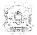
図1は、本発明を適用して好適な遊技機の一例としてのパチンコ機の遊技盤の構成例を示すもので、この実施例ではいわゆる「第1種」に属するタイプのパチンコ機の遊技盤を示す。 FIG. 1 shows an example of the configuration of a game board of a pachinko machine as an example of a suitable game machine to which the present invention is applied. In this embodiment, a game board of a pachinko machine of the type belonging to the so-called “first type”. Indicates.
図1において、符号100で示されているのは遊技盤であり、この遊技盤100の前面に、下方より発射された遊技媒体としての遊技球を遊技盤上部に誘導する円弧状のガイドレール101、可変表示を利用した特別遊技を行なう特別図柄表示装置102、普通電動役物からなり上記特別遊技の起動条件を与える特図始動入賞口103、上記普通電動役物の始動条件を与える普図始動ゲート104,105、アタッカーと呼ばれる変動入賞装置106、一般入賞口107,108,109,110,111、特図始動入賞口への入賞球数を所定数(例えば最大4個)まで記憶する特図始動入賞記憶表示器121、可変表示を利用した補助遊技を行なう普通図柄表示器122、普図始動ゲートへの遊技球の通過数を所定数(例えば最大4個)まで記憶する普図始動記憶表示器123、遊技の演出効果を高める装飾ランプ124,125、打球の流れにランダム性を与える風車と呼ばれる打球方向変換部材126と多数の障害釘(図示略)が設けられている。
In FIG. 1,
特に限定されるわけでないが、この実施例では、遊技盤100に設けられた全ての入賞口103〜111のそれぞれに対応してそこへ入賞した球を検出するためにマイクロスイッチや非接触型のセンサからなる入賞センサが設けられている。すなわち、特図始動入賞口103の内部には特図始動センサS1が配置され、変動入賞装置106の内部にはカウントセンサS4と継続入賞センサS5、一般入賞口107〜111の内部には入賞センサS4〜S10がそれぞれ配置されている。そして、遊技球がこれらの入賞口に入賞すると、入賞センサから入賞球検出信号が後述の遊技制御装置210へ送られ、遊技制御装置210から排出制御装置220へ賞球数データが送信されるようになっている。
Although not particularly limited, in this embodiment, a micro switch or a non-contact type is used to detect a ball that has won a prize corresponding to each of all the winning
ここで、上記普図始動ゲート104,105への通過球が検出されると普通図柄表示器122が所定時間可変表示動作されるとともに、その間にさらに普図始動ゲート104,105への通過球が発生するとその球数が記憶されその記憶数に応じて普図始動入賞記憶表示器123が点灯される。そして、普通図柄表示器122の可変表示が停止したときにその表示内容が所定の態様になると上記普通電動役物からなる特図始動入賞口103が開成される。
Here, when a passing ball to the above-mentioned general-
この開成された特図始動入賞口103あるいは閉成状態の特図始動入賞口103に遊技球が入賞すると特定図柄表示器102が所定時間可変表示動作されるとともに、その間にさらに特図始動入賞口103への入賞球が発生するとその球数が記憶されその記憶数に応じて特図始動入賞記憶表示器121が点灯される。そして、後述するように、特別始動入賞口103への入賞に関連して抽出された乱数値の判定を行なった後に、当該判定結果に対応した停止図柄を導出すべく、特別図柄表示器102における可変表示を開始し所定時間経た後に前記停止図柄にて停止すべく可変表示を終了する。この可変表示の終了を契機に、当該可変表示に係わった前記判定結果が当たりの場合は、上記変動入賞装置106が所定時間又は所定入賞球数に達するまで開成される。
When a game ball is won in the opened special figure starting winning
さらに、上記変動入賞装置106内には一般入賞領域と継続入賞領域とが設けられており、継続入賞領域に遊技球が入賞したことを条件として上記変動入賞装置106の開成動作が所定回数まで繰り返される。
Furthermore, a general winning area and a continuous winning area are provided in the variable winning
遊技盤100における上記のような遊技の進行の制御が上記遊技制御装置210によって行なわれる。遊技制御装置210は、遊技盤毎に制御内容が異なるため、遊技盤100が交換されると新たなものと入れ換えられることが普通である。したがって、一般には遊技制御装置210は、遊技盤100の裏面側に取り付けられて遊技盤と共に交換できるように構成される。ただし、必ずしもそのような構成に限定されるものではない。
Control of the progress of the game as described above on the
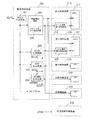
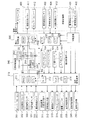
図2は上記遊技盤の裏面を含むパチンコ機の裏側に設けられる制御系全体の構成例を示す。図2において、210は上記遊技盤100における上記のような遊技の進行の制御を行なう遊技制御装置である。220は遊技制御装置210から賞球数データを受けて球排出装置より所定数の賞球を排出させたり、いわゆるCR機と呼ばれる遊技機では隣接したカード式球貸機(図示省略)から球貸し数データを受けて所定数の貸し球を排出させる排出制御装置である。
FIG. 2 shows a configuration example of the entire control system provided on the back side of the pachinko machine including the back side of the game board. In FIG. 2,
また、230は前記遊技盤100の前面に設けられている特別図柄表示装置102など遊技内容に関連する表示を行なう表示器の制御を行なう表示制御装置、240は遊技盤前面の装飾ランプ124,125など装飾用の表示器の制御を行なう装飾制御装置、250はスピーカ(図示省略)を制御して遊技内容に関連した効果音を発生させる音制御装置、260はAC24Vのような交流電源電圧に基づいてこれらの制御装置210〜250で必要とされる直流電源電圧DC32V,12V,5Vを発生するAC−DCコンバータやDC−DCコンバータからなるDC生成回路261,262,263やバックアップ電源VBB(DC5V)を供給するVBB生成回路264などにより構成された電源供給装置である。さらに、パチンコ機の裏側には上記制御装置210〜250とは別個に、上記電源供給装置260からの直流電源電圧によらず直接AC24Vを受けて打球発射装置を制御する発射制御装置270が設けられている。
Further, 230 is a display control device for controlling a display for performing display related to game contents such as a special
この実施例においては、上記電源供給装置260に付随して、上記DC生成回路261で生成された直流電圧DC32Vを監視し、それが23〜24Vのような電圧まで低下したときに停電と判定し検出信号PDDを出力する停電検出回路265が設けられている。停電検出回路265から出力される停電検出信号PDDは、遊技制御装置210のマイクロコンピュータ211と排出制御装置220のマイクロコンピュータ221のマスク不能な割込み入力端子NMIにそれぞれ入力される。
In this embodiment, the DC voltage DC32V generated by the
また、上記停電検出回路265には、停電検出信号PDDを遅延して上記制御装置210〜250へリセット信号RSとして出力するリセット信号出力遅延回路266が設けられている。リセット信号出力遅延回路266における遅延時間は遊技制御装置210や排出制御装置220における停電処理を実行するのに要する時間よりも若干長く設定されている。これによって遊技制御装置210および排出制御装置220は、停電処理による必要なデータや内部状態をバックアップされたRAMに退避した後で、リセット信号によりハード的に停止状態にロックされ、停電処理終了後電源が完全に断になるまでマイクロコンピュータが動作可能な状態のまま放置されるのを回避するように構成されている。
The power
一方、上記制御装置210〜250のうち遊技制御装置210と排出制御装置220には、上記停電検出回路265からの遅延リセット信号RSを受けてこれをさらに所定時間遅延してそれぞれマイクロコンピュータ211と221のリセット端子へ入力するリセット信号第1遅延回路212とリセット信号第2遅延回路222が設けられている。
On the other hand, among the
このリセット信号第1遅延回路212とリセット信号第2遅延回路222は、リセットの解除のタイミングのみを遅延するもので、それぞれにおける遅延時間T4とT3は、T4>T3となるように設定され、これによって図3に示すように、停電発生時にはマイクロコンピュータ211と221を同時にリセットさせる一方、停電復旧時には遊技制御装置210のマイクロコンピュータ211よりも排出制御装置220のマイクロコンピュータ221の方が先にリセットを解除されて制御動作を開始するように構成されている。また、この実施例においては、遊技制御装置210および排出制御装置220以外の制御装置230〜250は、停電検出回路265からのリセット信号RSを遅延する遅延回路を有しておらず、遊技制御装置210および排出制御装置220よりも早くリセット状態が解除されるように構成されている。
The reset signal
図4には、上記制御装置のうち遊技制御装置210と排出制御装置220の入出力およびバックアップ手段の構成例が示されている。
FIG. 4 shows a configuration example of input / output and backup means of the
図4に示されているように、遊技制御装置210はパチンコ遊技等に必要な役物制御を行う半導体集積回路化されたワンチップマイコン(広義のCPU)からなる遊技用マイクロコンピュータ211と、リセット信号を遅延する前述のリセット信号第1遅延回路(DLY1)212と、水晶発振子の発振信号を分周して所定の周波数のクロック信号を得るクロック生成回路(CLK1)213と、各種センサからの信号を受け入れたりソレノイドなどの駆動手段に対する駆動信号や他の制御装置に対する制御信号を出力したりする入出力インターフェース214とを含んで構成される。
As shown in FIG. 4, the
この実施例では、インタフェース214の出力ポートは、例えば出力データをラッチするフリップフロップとラッチデータを外部端子へ出力するバッファ回路とから構成され、このうちフリップフロップのクリア端子に前記リセット信号RSが入力されるようにされている。これによって、停電復旧時にリセット信号RSが立ち上がって遊技制御装置210のCPUが制御を開始するまでの間、リセット信号RSによって排出制御装置220との通信線が接続された出力ポートを含む所定の出力ポートが強制的にオフデータを出力する状態に固定されるようになっている。
In this embodiment, the output port of the
上記遊技用マイクロコンピュータ211は、演算制御手段としての中央処理ユニット(CPU)と、記憶手段としてROM(リードオンリメモリ)およびRAM(ランダムアクセスメモリ)、割込み制御回路(図示省略)などを内蔵しており、いわゆるアミューズチップ用のICとして製造されている。CPUが行なう遊技進行制御に必要なプログラムや賞球数データはROMに格納されている。
The
遊技制御装置210には、入出力インターフェース214を介して、前記特図始動入賞口103内の特図始動センサSS1、普図始動ゲート104,105内の普図始動センサSS2,SS3、変動入賞装置106内の一般入賞領域に対応したカウントセンサSS4と継続入賞領域に対応したV入賞センサSS5、一般入賞口107〜111内の入賞センサSS4〜SS10からの検出信号の他、受け皿が遊技球で満杯になったことを検出するオーバーフロー検出器301からの信号、貯留タンクの遊技球を後述する球排出装置400へ供給するための導出樋(いわゆるシュート)の下流側に設けられ、球排出装置400へ供給可能な遊技球の有無を検出する半端球検出器302からの信号、遊技盤100の前面側を覆うガラス板を保持する金枠が開放されたことを検出する金枠開放検出器303からの信号、球排出装置400内の賞球検出センサ401,402からの信号などが入力される。
The
一方、遊技制御装置210からは入出力インターフェース214を介して、図示しない遊技店の管理装置に対してデータを送信するデータ出力端子311への信号、試験時に内部状態を出力する端子312への信号、普通電動役物(特図始動入賞口103)の表示ランプ313の駆動信号、変動入賞装置106の大入賞口を開閉駆動するアタッカーソレノイド314の駆動信号、普通電動役物を開閉駆動する普電ソレノイド315の駆動信号、排出制御装置220、表示制御装置230、装飾制御装置240、音制御装置250に対するデータ信号などが出力される。
On the other hand, from the
排出制御装置220は、ワンチップマイコンからなる制御用マイクロコンピュータ221と、リセット信号を遅延する前述のリセット信号第2遅延回路(DLY2)222と、水晶発振子の発振信号を分周して所定の周波数のクロック信号を得るクロック生成回路(CLK2)223と、各種センサからの信号を受け入れたりソレノイドなどの駆動手段に対する駆動信号や他の制御装置に対する制御信号を出力したりする入出力インターフェース224とを含んで構成される。制御用マイクロコンピュータ221は、演算制御手段としての中央処理ユニット(CPU)と、記憶手段としてROMおよびRAM、割込み制御回路(図示省略)などから構成される。そして、CPUが行なう遊技球の排出(賞球排出および貸球排出を含む)などの排出制御に必要なプログラムはROMに格納されている。
The
排出制御装置220には、入出力インターフェース224を介して、前記遊技制御装置210からの賞球データ信号や、球排出装置400内の賞球検出器401,402,貸し球検出器403,404からの検出信号、カード式球貸しユニット500からの貸し球データ信号などが入力される。一方、排出制御装置220からは入出力インターフェース224を介して、球排出装置400内の排出モータ411に対する駆動信号、排出停止用のストッパソレノイド412の駆動信号、賞球と貸し球の排出流路を切り換える流路切換ソレノイド413の駆動信号などが出力される。
To the
電源供給装置260には、DC5Vのロジック用電源電圧を生成するDC生成回路263からのDC電圧をアノード端子に受けるダイオードD1と、該ダイオードD1のカソード端子と接地点との間に接続された比較的容量値の大きなスーパーコンデンサC1とからなるバックアップ電源264が設けられ、このバックアップ電源264からの電源電圧VBBが上記遊技制御装置210内のRAMと排出制御装置220内のRAMにそれぞれ供給され、停電時にRAMの情報を保持するように構成されている。
The
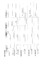
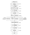
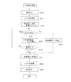
次に、上記遊技制御装置210による遊技制御の手順の一例を、図5〜図9を用いて説明する。図5〜図9のうち図5および図6は遊技制御装置210によって実行されるメイン処理(第1遊技制御処理)の手順を示す。このメイン処理は、遊技機の電源が投入されたり、停電が回復したときに実行されるものである。図7は遊技制御装置210によって実行される通常割込処理(第2遊技制御処理)の手順を示すもので、例えば1msecのような周期でソフト的なタイマ割込みにより実行される処理である。また、図8は遊技制御装置210によって実行される強制割込み処理(第3遊技制御処理)の手順を示すもので、停電検出回路265からの停電検出信号PDDが割込み端子NMIに入力されることに基づいて実行される処理である。さらに、図9は図7の通常割込処理中における払出コマンド送信処理の具体的な手順を示すものである。
Next, an example of a game control procedure by the
図5および図6のメイン処理においては、CPUが先ずCPU内部を初期化し全出力ポートをオフ状態(論理“0”を出力する状態)に設定する(ステップS1,S2)。次に、ステップS3で停電フラグをチェックして正常か否かすなわち停電が発生していたことを示す所定のコード(例えば01010101)になっているか否か判定し、所定のコードのときはステップ4aへ移行し、所定のコード以外のときは通常の電源投入と判断してステップS5aへ移行する。 In the main processing of FIGS. 5 and 6, the CPU first initializes the inside of the CPU and sets all output ports to an off state (a state in which logic “0” is output) (steps S1 and S2). Next, in step S3, the power failure flag is checked to determine whether or not it is normal, that is, whether or not a predetermined code (for example, 01010101) indicating that a power failure has occurred. If it is not a predetermined code, it is determined that the power is normally turned on, and the process proceeds to step S5a.
上記停電フラグはRAM内の1バイトで構成され、電源が供給されていない状態(例えばバックアップ用のコンデンサC1が放電された状態)から電源が投入された場合には例えばバイナリコードで“11110000”(16進数で“F0”、以下これをF0Hと記す)など固有のデータ(メーカーや品種によって異なる)が当該RAMに設定されており、停電が発生すると図8の強制割込処理の中で例えばバイナリコードで“01010101”(55H)に設定されるようになっている。従って、CPUは停電フラグが55Hであれば停電からの復帰であると、また55H以外であれば通常の電源立ち上げであると
認識することができる。
The power failure flag is composed of 1 byte in the RAM, and when power is turned on from a state where power is not supplied (for example, a state where the backup capacitor C1 is discharged), for example, “11110000” (in binary code) Specific data such as “F0” in hexadecimal (hereinafter referred to as “F0H”) (which differs depending on the manufacturer and product type) is set in the RAM. When a power failure occurs, for example binary in the forced interrupt process of FIG. The code is set to “01010101” (55H). Therefore, if the power failure flag is 55H, the CPU can recognize that the power has returned from the power failure, and if it is other than 55H, the CPU can recognize that the power supply is normal.
CPUはステップS3で停電復帰と判定するとステップ4aへ移行して、先ずバックアップされたRAM内に退避されていたスタックポインタをCPU内部に復帰させてから停電復旧のための初期化処理を行なう(ステップS4c)。停電復旧のための初期化処理は、停電発生時にバックアップRAMに退避されていたレジスタ類を停電発生前の状態へ復旧させたりRAM内の所定領域をクリアしたりする処理である。 If the CPU determines in step S3 that the power failure has been restored, the process proceeds to step 4a. First, the stack pointer saved in the backed-up RAM is restored to the CPU, and then initialization processing for power failure recovery is performed (step S3). S4c). The initialization process for power failure recovery is a process for restoring the registers saved in the backup RAM when a power failure occurs to the state before the power failure occurs or clearing a predetermined area in the RAM.
その後、CPUは復旧された停電時に保存されていたデータに基づいて排出制御装置220への賞球数データの出力ポートを含む所定の出力ポートへデータを出力すなわち停電時の出力ポートの状態を再現させる(ステップS4c)。これによって、賞球数データの出力ポートはオフデータからオフデータ以外のデータに変化するため、排出制御装置220はこの賞球数データを監視することにより遊技制御装置210が動作開始したことを認識することができる。
After that, the CPU outputs data to a predetermined output port including the output port of the prize ball number data to the
次に、遊技制御装置210のCPUは、排出制御装置220以外の制御装置へ停電復旧処理が終了したことを知らせる処理を行なう(ステップS4d)。それから割込みタイマを起動し、停電発生前は割込み禁止状態にされていたかをステップS22で設定される停電フラグを参照して判定する(ステップS4e,S4f)。そして、停電前が割込み禁止のときは、バックアップRAMに退避されていたプログラムカウンタの値などを元のレジスタに復帰させ割込みを禁止した後に、また停電前が割込み禁止でないときはバックアップRAMに退避されていたプログラムカウンタの値などを元のレジスタに復帰させ割込みを許可した後に、それぞれ停電復旧処理を終了する(ステップS4g,S4h,S4i,S4j)。以上の処理により遊技制御装置内部は停電発生直前の状態に戻るので、その後CPUは、停電検出時に停止したプログラムの命令位置から制御を再開することとなる。
Next, the CPU of the
なお、図5のフローでは、ステップS4hで割込みを禁止しているが、メイン処理の最初のステップで割込み禁止を設定するようにしても良い。その場合には、この停電復旧処理に入る前に割込み禁止が設定されるので、ステップS4gを行なった後、再度ステップS4hで割込み禁止を行なうことなく処理を再開させるようにする。 In the flow of FIG. 5, interrupt is prohibited in step S4h, but interrupt prohibition may be set in the first step of the main process. In that case, since prohibition of interruption is set before entering this power failure recovery processing, after performing step S4g, the processing is resumed without interrupting prohibition again in step S4h.
一方、CPUはステップS3で通常電源立ち上げと判定するとステップ5aへ移行して割込み制御回路に対して通常割込みの受付けを禁止させてから、スタックポインタの設定やRAM内の所定領域のクリア、RAM内の検査領域へのチェックデータの書込みや各種レジスタ類の初期値設定などの初期化処理(ステップS5b)を行なってから、割込みタイマを起動(ステップS5c)し、ステップS5aで禁止した割込みを許可(ステップS5d)した後、符号Aに従って図6の処理へ移行する。 On the other hand, if the CPU determines in step S3 that the normal power supply is turned on, it proceeds to step 5a and prohibits the interrupt control circuit from accepting a normal interrupt, and then sets the stack pointer, clears a predetermined area in the RAM, After performing initialization processing (step S5b) such as writing check data to the inspection area and setting initial values of various registers (step S5b), the interrupt timer is started (step S5c), and the interrupts prohibited in step S5a are permitted. After (step S5d), the process proceeds to the process of FIG.
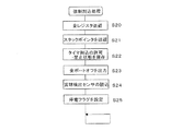
図6の処理は、正常な状態において繰返し行なわれる通常遊技制御のループ処理であり、先ずステップS5eでRAM内の検査領域のデータをチェック、具体的にはステップS5bの初期化処理等で書き込んだ所定のチェックデータが壊れていないか1回のループ毎に検査し、異常があったときは図5の符号「B」のようにステップS5aへジャンプして割込みを禁止してからチェックデータの書込みを含む初期化処理(ステップS5b)をやり直す。 The process of FIG. 6 is a normal game control loop process that is repeatedly performed in a normal state. First, in step S5e, the data in the inspection area in the RAM is checked, specifically written in the initialization process in step S5b. Check whether the predetermined check data is broken or not every loop, and if there is an abnormality, jump to step S5a as shown by symbol “B” in FIG. The initialization process including (Step S5b) is performed again.
ステップS5fでRAM内の検査領域のチェックデータが正常であると判定したときはステップS5gへ進んで、遊技盤に設けられている所定の検出器(センサ)の信号入力状態を判定する入力判定処理を行なう。また、この入力判定処理では後述の通常割込みルーチン(図7)中のスイッチ入力読込み処理(ステップS13)で設定されたフラグを監視して、特図始動センサの入力フラグに“1”が立っていると“検出信号有り”と判定して後述のステップS16で生成される遊技用乱数を抽出し記憶したり、各センサの入力フラグに対応して賞球数データ(例えば7個あるいは15個)を設定する。 When it is determined in step S5f that the check data in the inspection area in the RAM is normal, the process proceeds to step S5g to determine the signal input state of a predetermined detector (sensor) provided on the game board. To do. Also, in this input determination process, the flag set in the switch input reading process (step S13) in the normal interrupt routine (FIG. 7) described later is monitored, and “1” is set in the input flag of the special figure start sensor. If it is determined that there is a “detection signal”, the game random number generated in step S16 described later is extracted and stored, or the number of award balls (for example, 7 or 15) corresponding to the input flag of each sensor. Set.
なお、この入力判定処理中は通常割込みにより処理が中断されて他の処理(例えば乱数更新処理)が実行されると不具合が生じるおそれがあるので、処理が中断されないようにするため処理の先頭で強制割込み以外の割込みが禁止され、処理が終了した時点で割込みが解除されるようにされている。そして、この処理の途中で停電検出による強制割込みが入ると、後述の強制割込み処理(図8)のステップS22で中断する処理(この場合入力判定処理)は割込み禁止が設定された状態にあることを認識し、割込禁止フラグが保存される。この結果、停電復帰時に、前記停電復旧処理のステップS4fで停電発生前が割込み禁止になっていたかの判定が行なわれたときに、この場合には割込禁止フラグが設定されているので、ステップS4hで割込み禁止を設定して中断されていた当該入力判定処理が再開される。従って、処理が途中から再開されても割込み禁止は行なわれているため、停電復帰後もこの入力判定処理中は処理が中断されないようになる。 Note that during this input determination process, if the process is interrupted by a normal interrupt and another process (for example, random number update process) is executed, there is a risk of malfunction, so at the beginning of the process to prevent the process from being interrupted Interrupts other than forced interrupts are prohibited, and interrupts are released when processing is completed. If a forced interruption due to a power failure is detected in the middle of this process, the process interrupted in step S22 of the forced interrupt process (FIG. 8) described later (in this case, the input determination process) is in a state in which interrupt inhibition is set. And the interrupt prohibition flag is saved. As a result, when it is determined in step S4f of the power failure recovery process whether interruption was prohibited before the occurrence of the power failure at the time of power failure recovery, an interrupt prohibition flag is set in this case, so step S4h The input determination process that has been interrupted by setting the interrupt prohibition in step 1 is resumed. Therefore, even if the process is resumed from the middle, the interruption is prohibited, so that the process is not interrupted during the input determination process even after the power failure is restored.
次のステップS5hでは、変動入賞装置106が開成されていないにもかかわらずカウントセンサSS4やV入賞センサSS5からの検出信号があったような場合にこれをエラーとするなどのエラー監視処理を行なう。続いて、ステップS5iでは、特別図柄表示装置102における可変表示を制御したり、音制御装置に対する効果音の発生指令や装飾制御装置に対する装飾表示の指令を与えるためのコマンドの設定をして通常遊技表示や大当り時の演出表示などの特図ゲーム処理を行なう。この処理ルーチンの中で、上記ステップS5gで取得した乱数が大当りとして設定された値に一致したか否かの判定も行なわれる。また、この特図ゲーム処理中も、処理が途中で中断されないようにするため、処理の先頭で強制割込み以外の割込みが禁止され、処理が終了した時点で割込みが解除されるようにされる。
In the next step S5h, an error monitoring process such as setting an error when there is a detection signal from the count sensor SS4 or the V winning sensor SS5 even though the
ステップS5jでは、普通図柄表示装置122における可変表示を制御するためのフラグを設定したり、普図の表示状態に合わせて音制御装置に対する効果音の発生指令や装飾制御装置に対する装飾表示の指令を与えるためのコマンドを設定して普図始動時の演出表示などの普図ゲーム処理を行なう。そして、次のステップS5kで上記ステップS5jで設定された情報に基づいて普図を可変表示させるためのデータを出力領域に設定する普図可変制御処理が行なわれる。上記普図ゲーム処理および普図可変制御処理中も、処理が途中で中断されないようにするため処理の先頭で強制割込み以外の割込みが禁止され、処理が終了した時点で割込みが解除されるようにされる。
In step S5j, a flag for controlling the variable display on the normal
次に、ステップS5lでは、上記特図ゲーム処理や普図ゲーム処理における処理状態(遊技状態)に基づいて、変動入賞装置106を開成するためのソレノイドや普通電動役物からなる特図始動入賞口103を開成するためのソレノイドを制御する信号を対応する出力ポートへ出力させるためのオン・オフデータを出力領域に設定する処理が行なわれる。続いて、ステップS5mで、特図ゲーム処理における処理状態に基づいて大当り信号や特図変動信号等を管理装置へ送信するためのデータを設定する処理が行なわれる。
Next, in step S51, based on the processing state (game state) in the special figure game process or the general figure game process, a special figure start prize opening made up of a solenoid for opening the
ステップS5nでは、入力判定処理や特図ゲーム処理ルーチンの中で設定されたコマンドを送信順に並び変えて出力領域に設定する処理が行なわれる。ステップS5oでは、ステップS5iで使用されるゲーム演出用乱数を更新(例えば乱数+1)するための処理が行なわれ、大当たり前のいわゆるリーチ演出等の処理を選択する際に使用される。そして、この乱数更新処理が終了するとステップS5eへ戻って上記処理5e〜5oを繰返し実行する。 In step S5n, a process for rearranging the commands set in the input determination process and the special figure game process routine in the order of transmission and setting them in the output area is performed. In step S5o, a process for updating the game effect random number used in step S5i (for example, random number + 1) is performed, and used when selecting a process such as a so-called reach effect. When this random number update process is completed, the process returns to step S5e and the above processes 5e to 5o are repeatedly executed.
そして、上記処理5e〜5oを繰返している間にステップS5cで起動したタイマによる割込みが1mS毎に入りそのとき割込み禁止がかかっていないと、CPUは図7の通常割込み処理を実行する。 Then, while the processes 5e to 5o are repeated, if the interruption by the timer activated in step S5c enters every 1 mS and the interruption is not prohibited at that time, the CPU executes the normal interruption process of FIG.
1mS毎の通常割込み処理においては、先ずステップS10で強制割込み以外の割込みを禁止してから、レジスタの値をRAMのスタックエリアに退避(ステップS11)し、マイクロコンピュータの暴走を監視するためのウォッチドックタイマICをリセットする(ステップS12)。このウォッチドックタイマICは所定時間以内にリセットされないと警報信号を発生するので、例えば図6のメイン処理中のステップS5gや5i,5jのように処理に入るときに割込みを禁止する処理の中でノイズ等によりマイクロコンピュータが暴走してしまい通常割込み処理に移行できないような場合に、異常が発生したことをCPUに知らせることができる。 In normal interrupt processing every 1 mS, first, interrupts other than forced interrupts are prohibited in step S10, and then the register value is saved in the RAM stack area (step S11) to monitor the microcomputer runaway. The dock timer IC is reset (step S12). Since this watchdog timer IC generates an alarm signal if it is not reset within a predetermined time, for example in steps S5g, 5i, and 5j in the main process of FIG. When the microcomputer runs out of control due to noise or the like and cannot shift to normal interrupt processing, the CPU can be notified that an abnormality has occurred.
次のステップS13では、遊技盤に設けられている各種検出器からの入力信号の状態を割込み毎すなわち1mS毎に読込み、例えばロウレベルからハイレベルへ変化しかつハイレベルが2回連続したら検出信号有りと判定し入力フラグを立てるスイッチ入力読込み処理を行なう。それから、図6のメイン処理中のステップS5lでのソレノイド駆動処理やステップS5mでの外部情報編集処理等で出力領域に設定された出力データを出力ポートに設定して信号を出力させる処理(ステップS14)、ステップS5nのコマンド編集処理等で出力領域に設定された出力データを出力ポートに設定して他の制御装置に対してコマンドを送信させる処理(ステップS15a,S15b,S15c,S15d)を行なう。 In the next step S13, the state of input signals from various detectors provided on the game board is read at every interruption, that is, every 1 mS. For example, when the low level changes to the high level and the high level continues twice, the detection signal is present. Switch input reading processing is performed to set an input flag. Then, a process of setting the output data set in the output area in the output region in the solenoid driving process in step S51 or the external information editing process in step S5m in the main process of FIG. 6 and outputting a signal (step S14). ), Processing (steps S15a, S15b, S15c, S15d) in which the output data set in the output area in step S5n is set as an output port and commands are transmitted to other control devices is performed.
なお、これらの送信処理のうち表示制御装置に対する表示コマンド送信処理は割込み毎に毎回行なわれるのに対し、排出制御装置に対する払出コマンドの送信処理と音制御装置に対する音声コマンドの送信処理と装飾制御装置に対するランプ点灯コマンドの送信処理は、高速性が要求されていないため時分割処理とされ、3回の割込み処理に1回つまり3mS毎に実行されるように構成されている。 Of these transmission processes, the display command transmission process for the display control apparatus is performed every interruption, whereas the payout command transmission process for the discharge control apparatus, the voice command transmission process for the sound control apparatus, and the decoration control apparatus The process for transmitting the lamp lighting command is time-division processing because high speed is not required, and is configured to be executed once every three interrupt processes, that is, every 3 mS.
次の遊技用乱数更新処理(ステップS16)では特別図柄表示装置102上で行なわれる特図ゲームの当たりを決定する乱数や普通図柄表示装置122上で行なわれる普図ゲームの当たりを決定する乱数を生成し、タイマ更新処理(ステップS17)では図6のメイン処理ルーチンの各処理で使用される時間を生成する。なお、ステップS16での乱数更新処理も単に前回の値に+1するだけの処理とすることができる。この場合、更新後の数値は連続した数値になるが、この数値をループ処理であるメイン処理ルーチンのステップS5gで取得するタイミングが乱数更新タイミング(1mS毎)とずれているため、取得した数値は乱数となる。
In the next game random number update process (step S16), a random number for determining the hit of the special figure game performed on the special
以上の処理が終了すると、ステップS11でスタック領域に退避しておいたレジスタの値を元のレジスタに戻してから、ステップS10で禁止した割込みを許可して、メイン処理ルーチンへ復帰して該割込み処理開始時に中断した処理を再開する(ステップS18,S19)。 When the above processing is completed, the value of the register saved in the stack area in step S11 is returned to the original register, then the interrupt prohibited in step S10 is permitted, the process returns to the main processing routine, and the interrupt is performed. The process interrupted at the start of the process is resumed (steps S18 and S19).
図8には停電発生時に実行される強制割込み処理の手順の一例が示されている。この強制割込み処理は、電源供給装置から割込み入力端子NMIに停電検出信号PDDが入力されることによって開始され、CPUは先ず全てのレジスタの値をバックアップされたRAM内のスタックエリアに退避(ステップS20)してから、最後にそのスタックエリアの先頭番地を示すスタックポインタの値をRAM内の所定番地に退避する(ステップS21)。 FIG. 8 shows an example of a procedure for forced interrupt processing executed when a power failure occurs. This forced interrupt process is started when a power failure detection signal PDD is input from the power supply device to the interrupt input terminal NMI. First, the CPU saves all register values in the backed up RAM stack area (step S20). After that, the value of the stack pointer indicating the top address of the stack area is saved at a predetermined address in the RAM (step S21).
次に、タイマによる通常割込みを許可しているか禁止しているかを示すフラグ(例えば割込禁止フラグ)の状態をRAM内の所定番地に保存する(ステップS22)。この保存フラグは、停電復旧後にメイン処理ルーチンのステップS4fで参照され、強制割込みが発生した時点のメイン処理で割込み禁止が設定されていたか否かが判定される。その後、ステップS23で全出力ポートにオフデータ(“0”)を設定して、停電時に不具合が生じないようにアタッカーなどの部品や通信線のデータ等をソフトウェアによってオフ状態にする。 Next, the state of a flag (for example, an interrupt prohibition flag) indicating whether normal interruption by the timer is permitted or prohibited is stored at a predetermined address in the RAM (step S22). This save flag is referred to in step S4f of the main processing routine after restoration of the power failure, and it is determined whether or not interrupt prohibition is set in the main processing at the time when the forced interrupt occurs. After that, in step S23, off data ("0") is set for all output ports, and parts such as an attacker, communication line data, and the like are turned off by software so as not to cause a failure during a power failure.
それから、球排出装置400内の賞球検出器401,402の入力信号を読み込んで停電発生時の球排出装置400の排出状態をバックアップRAMに保存(ステップS24)し、最後にRAMの所定番地に割り付けられた停電フラグを、停電発生を示す状態(55H)に設定して待機状態となる(ステップS25)。そして、この待機状態中に、CPUはリセット信号第1遅延回路からの信号によりリセット状態とされる。すなわち、遊技制御用CPUは先ずソフトウェアにより遊技制御を停止してから、リセット信号によりハード的に停止状態にロックされるように構成されている。これによって、停電発生時の不具合の発生が確実に回避されることとなる。
Then, the input signals of the
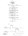
図9(a)には図7の通常割込み処理ルーチンの払出コマンド送信処理(ステップ15b)の具体的な手順が、また図9(b)にはそのタイミングチャートが示されている。なお、本実施例においては、排出すべき賞球数を表わす排出制御データD0〜D7とスタート信号STTとストローブ信号STBを合わせたものを払出コマンドと称する。
FIG. 9A shows a specific procedure of the payout command transmission process (
同図に示されているように、払出コマンド送信処理では、先ず第1のステップS30で送信すべき払出コマンドが設定されているか否か判定して、設定されていなければそのまま通常割込み処理ルーチンへリターンし、設定されている場合は排出制御装置220に対するスタート信号STTをハイレベルに変化させるようにスタート信号STTの出力ポートを“オン出力”に設定する(ステップS31)。そして、次のステップS32でスタート信号STTをロウレベルに変化させるようにスタート信号STTの出力ポートを“オフ出力”に設定する。これによって、図9(b)のように例えば20マイクロ秒のような短い時間T1だけハイレベルのスタート信号STTが出力される。
As shown in the figure, in the payout command transmission process, it is first determined whether or not a payout command to be transmitted is set in the first step S30. If it is set, the output port of the start signal STT is set to “ON output” so that the start signal STT for the
次に、ステップS33で排出制御データD0〜D7を出力させるように出力ポートを設定した後、ストローブ信号STBをハイレベルに変化させるようにストローブ信号STBの出力ポートを“オン出力”に設定する(ステップS34)。そして、次のステップS35でストローブ信号STBをロウレベルに変化させるようにストローブ信号STBの出力ポートを“オフ出力”に設定する。これによって、図9(b)のように例えば30マイクロ秒のような時間T2だけハイレベルのストローブ信号STBが出力される。 Next, after setting the output port to output the discharge control data D0 to D7 in step S33, the output port of the strobe signal STB is set to “ON output” so as to change the strobe signal STB to high level ( Step S34). In the next step S35, the output port of the strobe signal STB is set to “off output” so as to change the strobe signal STB to the low level. As a result, as shown in FIG. 9B, a high level strobe signal STB is output for a time T2 such as 30 microseconds.
なお、上記スタート信号STTは排出制御装置220のCPU221の割込み端子に入力されており、排出制御装置220は割込み端子にスタート信号STTが入力されるとその立上がりタイミングt1で受信割込み処理へ移行し、ストローブ信号STBの立上がりタイミングt2でそのとき入力されている排出制御データD0〜D7を取り込むように制御プログラムが構成されている。
The start signal STT is input to the interrupt terminal of the
図9(b)からも分かるように、この実施例においては、遊技制御装置210からはいつでも排出制御データD0〜D7が出力されており、スタート信号STTの立ち上がり後に排出制御データD0〜D7が変化し、排出制御装置220はストローブ信号STBの立ち上がりタイミングで取り込むようになっている。
As can be seen from FIG. 9 (b), in this embodiment, the discharge control data D0 to D7 are always output from the
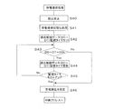
図10には、排出制御装置220における停電復帰処理の手順が示されている。なお、排出制御装置220の排出制御プログラムの全体構成は遊技制御装置210のプログラム構成とほぼ同じである。すなわち、割込みが入っていないときに繰返し実行するメイン処理と、タイマ割込みによる通常割込み処理と、停電検出信号PDDによる強制割込み処理と、前記受信割込み処理とにより構成されており、図10の停電復帰処理はメイン処理ルーチンの中で立上がりの際に停電フラグが停電発生を示していると開始される。停電発生時に実行される強制割込み処理は、図8に示されている遊技制御装置210の強制割込み処理とほぼ同じである。
FIG. 10 shows a procedure of power failure recovery processing in the
図10の停電復帰処理においては、先ず受信割込みを禁止(ステップS40)してから、停電復帰初期化処理(ステップS41)を行なった後、排出制御データD0〜D7を監視するための時間(例えば250マイクロ秒≒T4−T3)を設定する(ステップS42)。停電復帰初期化処理は、停電発生時にバックアップRAMに退避されていたレジスタ類を停電発生前の状態へ復旧させるとともにそれ以外レジスタ類は電源立上げ時の初期設定と同様な設定を行なう処理である。 In the power failure recovery process of FIG. 10, first, after reception interruption is prohibited (step S40), a power failure recovery initialization process (step S41) is performed, and then a time for monitoring the discharge control data D0 to D7 (for example, 250 microseconds≈T4-T3) is set (step S42). In the power failure recovery initialization process, the registers saved in the backup RAM at the time of the power failure are restored to the state before the power failure occurs, and other registers are set in the same manner as the initial settings at power-on. .
次に、ステップS43で、遊技制御装置210から入力されている排出制御データD0〜D7がすべてオフデータ(“0”)か否か判定する。停電復帰時には前述したように遊技制御装置210はリセット信号により排出制御装置220よりも長い時間リセットされ、リセットされている間は出力ポートを強制的にオフデータに設定しリセットが解除されると停電中断時の排出制御データ(オフデータ以外)を出力するように構成されている。そのため、排出制御装置220は遊技制御装置210よりも先に停電復帰し遊技制御装置210からの排出制御データD0〜D7がオフデータ以外になったことを検出すれば、遊技制御装置210が正常に停電復帰したと判定することができ、直ちにステップS46へ移行して、割込み入力端子へのスタート信号STTの入力による受信割込みを許可する受信割込み設定をしてメイン処理の中断した処理へリターンする。これによって、排出制御装置220は停電復旧後直ちに停電前の処理の継続を開始することができる。
Next, in step S43, it is determined whether or not the discharge control data D0 to D7 input from the
一方、ステップS43で排出制御データD0〜D7がオフデータであると判定したときはステップS44へ移行して排出制御データD0〜D7の監視タイマを更新して次のステップS45でその監視タイマがタイムアップしたか判定する。そして、タイムアップしていないときはステップS43へ戻って上記処理を繰返し、タイムアップしたときはステップS46へ移行して受信割込みを許可してメイン処理の中断した処理へリターンする。この場合、遊技制御装置210が正常に復帰していなくても中断した処理へリターンすることになるが、排出制御装置220はリターンしたメイン処理ルーチンの中の受信データ判別処理(図12)で、入力されている排出制御データD0〜D7を判定して無効あるいはエラーとして処理することとなるため何ら不都合はない。
On the other hand, when it is determined in step S43 that the discharge control data D0 to D7 are off data, the process proceeds to step S44, where the monitoring timer of the discharge control data D0 to D7 is updated, and the monitoring timer is timed in the next step S45. Judge whether it is up. If the time has not expired, the process returns to step S43 to repeat the above process. If the time has expired, the process proceeds to step S46 to allow reception interruption and return to the process where the main process is interrupted. In this case, even if the
次に、排出制御装置220における受信割込み処理の手順を、図11を用いて説明する。受信割込み処理は、遊技制御装置210からのスタート信号STTが排出制御装置220のCPUのマスク可能な割込み端子に、受信割込みが許可されていることを条件に入力されることによって開始され、まずステップS50で受信割込みおよび他の割込み(強制割込みを除く)を禁止し、ステップS51でレジスタの値をスタック領域に退避してから、ステップS52で通常時のストローブ信号STBの監視タイマをセットしてから遊技制御装置210からのストローブ信号STBがオンすなわちハイレベルに立ち上がったか否か判定する(ステップS53)。
Next, the procedure of reception interrupt processing in the
そして、立ち上がっていなければステップS55でストローブ信号STBの監視タイマを更新して次のステップS56でその監視タイマがタイムアップしたか判定する。そして、タイムアップしていないときはステップS53へ戻って上記処理を繰返し、タイムアップしたときすなわちスタート信号STTが入っても一定時間以内にストローブ信号STBが立ち上がらないときはステップS57へ移行する。一方、ステップS53でストローブ信号STBが立ち上がったと判定すると、ステップS54で排出制御データD0〜D7を読み込んでからステップS57へ移行する。 If not, the monitoring timer for the strobe signal STB is updated in step S55, and it is determined in the next step S56 whether the monitoring timer has expired. If the time is not up, the process returns to step S53 and the above processing is repeated. When the time is up, that is, when the strobe signal STB does not rise within a predetermined time even when the start signal STT is input, the process proceeds to step S57. On the other hand, if it is determined in step S53 that the strobe signal STB has risen, the discharge control data D0 to D7 are read in step S54, and then the process proceeds to step S57.
ステップS57では、受信割込みの再設定を行なう。受信割込みの再設定とは停電復帰により当該受信割込み処理を再開した場合に、待機中の受信割込みがあればそれをキャンセルし、改めて割込み入力端子へのスタート信号STTの入力による受信割込みを許可する処理である。この処理は、遊技制御装置210から排出制御装置220への払出コマンドの送信中に停電が発生すると、同一のスタート信号STTにより重複した受信割込みが発生することがあるのでそれによる誤動作を防止するためである。
In step S57, the reception interrupt is reset. Resetting the reception interrupt When the reception interrupt processing is resumed by recovery from a power failure, if there is a waiting reception interrupt, it is canceled, and a reception interrupt by inputting the start signal STT to the interrupt input terminal is permitted again. It is processing. In this process, if a power failure occurs during the transmission of a payout command from the
具体的には、スタート信号STTがハイレベルに変化した直後(図9bのT1の期間)に停電が発生し復旧した場合を考えると、この場合には遊技制御装置210側では、(1)図5の停電復帰処理(S4a〜S4i)のステップS4cで排出制御データ(今回送信するデータではなく前回のデータ)をポートへ出力してから、(2)中断した送信処理(図9のステップS31)を再開し改めてスタート信号STTをハイレベルに変化させる。一方、排出制御装置220は、遊技制御装置210の上記処理(1)により排出制御データD0〜D7がオフデータからオフデータ以外に切り替わったことを受けて直ちに受信割込みを許可する(図10ステップS43→S46参照)。そして、図11の中断した個所から処理を再開するため、停電前のスタート信号STTにより受信割込み処理を実行しているときに、遊技制御装置210の上記処理(2)によりハイレベルに変化されたスタート信号STTによって再度受信割込みが発生しこの割込みは待機状態とされる。この受信割込みをそのまま待機させておくと当該受信割込み処理が終了した後で再び同一のスタート信号STTにより重複した受信割込み処理が実行されてしまうこととなる。そこで、この実施例ではこれを回避するために、ステップS57で受信割込みの再設定を行なうようにしている。
Specifically, considering a case where a power failure occurs and is recovered immediately after the start signal STT changes to a high level (period T1 in FIG. 9b), in this case, the
そして、ステップS57の受信割込みの再設定を行なった後は、ステップS51でスタック領域に退避したレジスタの値を元のレジスタへ復帰させ、他の割込み入力を許可してメイン処理ルーチンへリターンする(ステップS58,S59)。
なお、図9(b)においてスタート信号STTが立ち下がった後で停電が発生した場合には、停電復帰後に遊技制御装置210からのスタート信号STTが再度立ち上げられることはないので、排出制御装置220側では排出制御データD0〜D7が変化した後に直ちに中断した処理を再開しても何ら問題はない。
After resetting the reception interrupt in step S57, the value of the register saved in the stack area in step S51 is restored to the original register, and another interrupt input is permitted and the process returns to the main processing routine ( Steps S58 and S59).
In addition, in the case where a power failure occurs after the start signal STT falls in FIG. 9B, the start signal STT from the
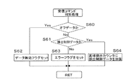
図12には、図11のステップS53で読み込んだ受信データすなわち排出制御データの判別処理の手順が示されている。この受信データ判別処理はメイン処理ルーチンの中に設けられており、受信データ判別処理では、まず受信した排出制御データがオフデータすなわちオール“0”か否かが判定される(ステップS60)。そして、オフデータであればステップS62でデータ無効フラグをセットして当該処理を終了し、メイン処理ルーチンの次のステップへ進む。 FIG. 12 shows a procedure for determining the received data read in step S53 of FIG. 11, that is, the discharge control data. This received data determination process is provided in the main process routine. In the received data determination process, it is first determined whether or not the received discharge control data is off data, that is, all “0” (step S60). If it is off data, a data invalid flag is set in step S62, the process is terminated, and the process proceeds to the next step of the main process routine.
一方、受信データがオフデータ以外のときはステップS61で排出制御データか否かが判定され、排出制御データでないときはステップS63でエラーフラグをセットし、排出制御データのときはステップS64で賞球排出カウンタに受信した排出制御データを加算して当該処理を終了し、メイン処理ルーチンの次のステップへ進む。メイン処理ルーチンでは、エラーフラグがセットされているとデータの再受信等のエラー処理を行ない、無効フラグがセットされていると読み込んだ受信データを廃棄したりする。当該処理が終了すると、メイン処理ルーチンの次のステップへ進む。そして、ステップS64で賞球排出カウンタにセットされた排出制御データはメイン処理ルーチンの賞球払出し処理にて参照され、セットされている排出数だけ賞球が球排出装置400より排出されるようになっている。
On the other hand, when the received data is other than off-data, it is determined whether or not it is discharge control data in step S61. If it is not discharge control data, an error flag is set in step S63, and if it is discharge control data, a prize ball is set in step S64. The received discharge control data is added to the discharge counter to end the process, and the process proceeds to the next step of the main process routine. In the main processing routine, if the error flag is set, error processing such as data re-reception is performed, and if the invalid flag is set, the read received data is discarded. When this process ends, the process proceeds to the next step of the main process routine. Then, the discharge control data set in the prize ball discharge counter in step S64 is referred to in the prize ball payout process of the main process routine so that the prize balls are discharged from the
特許請求の範囲に記載した以外の本発明の観点の代表的なものとして、次のものがあげられる。
(1)遊技領域における遊技の進行を制御するための遊技制御装置と、排出制御データに基づいて遊技媒体を排出する球排出装置を制御する排出制御装置とを備え、前記遊技制御装置および排出制御装置はそれぞれ制御上使用しているデータを停電発生時に保存可能に構成されているとともに、前記遊技制御装置から排出制御装置へ単一方向に通信可能に構成された遊技機であって、前記遊技制御装置は、前記排出制御装置へ排出制御データを送信中に停電発生を検出した場合には、実行している送信処理を中断し、出力している排出制御データ及び中断時の制御状態を保存する遊技制御側停電処理手段と、停電復帰時に、保存していた制御状態を復元するとともに保存していた排出制御データの出力を行なう遊技制御側処理再開手段とを備え、前記排出制御装置は、前記遊技制御装置から排出制御データを受信中に停電発生を検出した場合には、実行している受信処理を中断し、中断時の制御状態または中断時の制御状態と受信データを保存する排出制御側停電処理手段と、停電復帰時に、保存していた制御状態を復元した後、保存していた制御状態に応じて停電復帰後に入力される排出制御データまたは保存していた排出制御データに基づいて、停電発生時に中断した箇所から処理を再開する排出制御側処理再開手段とを備えたことを特徴とする遊技機。
(2)前記遊技制御装置は、電源が復旧してから制御を開始する停電復帰までの準備期間に亘って、前記排出制御装置との間の通信線が接続された出力ポートを準備期間論理値に固定する出力固定手段を備え、前記遊技制御側停電処理手段は、排出制御データを保存した後に前記出力ポートに前記準備期間論理値と同一のオフデータを設定し、前記遊技制御側処理再開手段は、排出制御データを送信中に停電が発生した場合には中断時の送信状態にかかわらず保存していた排出制御データを前記出力ポートに設定してから中断した送信処理を再開し、前記排出制御側処理再開手段は、停電復帰時に、前記通信線より入力される排出制御データがオフデータ以外になったことを条件として中断した受信処理を再開することを特徴とする(1)に記載の遊技機。
(3)前記排出制御側処理再開手段は、停電復帰時に、前記通信線より入力される排出制御データが所定時間以上オフデータである場合には、保存していた排出制御データを無効として中断した受信処理を再開することを特徴とする(2)に記載の遊技機。
(4)前記出力固定手段が前記出力ポートを準備期間論理値に固定する前記準備期間は、前記排出制御装置が電源復旧から制御を開始する停電復帰までに要する期間よりも長くなるように設定されていることを特徴とする(2)又は(3)に記載の遊技機。
(5)前記遊技制御装置は、前記遊技制御側停電処理手段および出力固定手段の能動中以外は、排出制御データとしてオフデータ以外のデータを前記出力ポートより出力することを特徴とする(2)から(4)のいずれかに記載の遊技機。
(1)に記載の発明では、遊技制御装置と排出制御装置は、各々停電発生を検出した場合に実行している処理を中断して中断時の制御状態を保存するため、停電復帰時に停電発生時に中断した処理を正確に再開することができる。しかも、遊技制御装置と排出制御装置は、各々通信中に停電発生した場合には送信中または受信した排出制御データも保存するため、停電復帰後に送信処理や受信処理をやり直す必要がなく直ちに中断した箇所から処理を再開することができる。その結果、送受信処理のプログラムが簡単になるとともに、停電復帰後の制御再開までの時間が短縮され、例えば持ち球が少ない状態で大当りが発生したときに停電が発生したような場合にも、停電復帰後速やかに賞球が排出されるようになり、遊技店と遊技者との間のトラブルの発生を回避することができる。
(2)に記載の発明では、遊技制御装置は電源復旧してから制御を開始するまで通信線が接続された出力ポートを準備期間論理値に固定し、制御を開始すると保存されていた排出制御データを元の出力ポートに設定するため、排出制御装置は、遊技制御装置に接続された通信線のデータがオフデータからオフデータ以外のデータに変わったことを検出することで遊技制御装置が制御を再開したことを確認することができ、これによって遊技制御装置と排出制御装置との間の通信が遊技制御装置から排出制御装置への単一方向通信であっても排出制御装置は停電復帰時に遊技制御装置が制御を再開したことをいち早く知ることができ、排出制御の開始を早めることができる。しかも、遊技制御装置と排出制御装置との間の通信が遊技制御装置から排出制御装置への単一方向通信であるため、排出制御装置に対して直接不正を行なって不当に賞球を排出させることが困難であるとともに、遊技制御装置からの指令によって動作する排出制御装置の側から遊技制御装置に対してアクセスが行なえないので、遊技制御装置に対する不正も行ないにくくなる。
(3)に記載の発明では、排出制御側処理再開手段は、停電復帰時に、前記通信線より入力される排出制御データが所定時間以上オフデータである場合には、保存していた排出制御データを無効として中断した受信処理を再開するように構成する。これにより、何らかの原因で遊技制御装置側の電源復帰処理が遅れても排出制御装置は速やかに制御を再開することができる。また、好ましくは、前記出力固定手段が出力ポートをオフデータに固定する前記準備期間(図3のT2+T4)は、前記排出制御装置が電源復旧から制御を開始する停電復帰までに要する期間(図3のT2+T3)よりも長くなるように設定する。これによって、停電復旧時に排出制御装置が遊技制御装置よりも先に停電復帰して通信線すなわち遊技制御装置の出力ポートのデータがオフデータからオフデータ以外のデータに変わるのを確実に検出することができ、システムの信頼性が向上する。
(4)に記載の発明では、前記遊技制御装置は、前記遊技制御側停電処理手段および出力固定手段の能動中以外は、排出制御データとしてオフデータ以外のデータを前記出力ポートより出力するようにする。これによって、停電復帰すると通信線すなわち遊技制御装置の出力ポートのデータが速やかにオフデータからオフデータ以外のデータに変わるようになり、これを受けて排出制御装置が停電発生時に中断した処理を再開するので、停電復旧時のシステムの立ち上がりが早くなる。
(5)に記載の発明では、前記排出制御データは0又は1の2値データで構成され、前記オフデータは全てが0又は全てが1のデータであり、前記遊技制御装置は、電源立ち上がり時に前記出力ポートに前記オフデータ以外のデータを設定するようにする。これによって、遊技制御装置は出力ポートのデータをオフデータからオフデータ以外のデータに変える処理を簡単に行なえるとともに、排出制御装置側においても通信線のデータがオフデータからオフデータ以外のデータに変化したことを容易かつ正確に判定することができる。
The following are typical examples of aspects of the present invention other than those described in the claims.
(1) A game control device for controlling the progress of a game in a game area, and a discharge control device for controlling a ball discharge device for discharging a game medium based on discharge control data, the game control device and the discharge control Each of the devices is a game machine configured to be able to store data used for control in the event of a power failure, and to be able to communicate in a single direction from the game control device to the discharge control device. When the control device detects the occurrence of a power failure during transmission of the discharge control data to the discharge control device, the control device interrupts the transmission process being executed and stores the output discharge control data and the control state at the time of the interruption. And a game control side process restarting means for restoring the stored control state and outputting the stored discharge control data when the power is restored. When the discharge control device detects the occurrence of a power failure while receiving the discharge control data from the game control device, the discharge control device interrupts the receiving process being executed, and the control state at the time of interruption or the control state at the time of interruption Emission control side power outage processing means for saving received data, and after restoring the saved control state at the time of power failure recovery, the discharge control data entered after power failure recovery or saved according to the saved control state A game machine comprising: a discharge control side process resuming means for resuming a process from a point where the power was interrupted based on the discharged control data.
(2) The game control device sets the output port connected with the communication line between the discharge control device and the logical value during the preparation period from the restoration of the power supply to the recovery from the power failure to start the control. The game control side power outage processing means sets the off data that is the same as the logical value of the preparation period in the output port after storing the discharge control data, and the game control side process restarting means If a power failure occurs during transmission of discharge control data, the saved discharge control data is set in the output port regardless of the transmission state at the time of interruption, and then the suspended transmission process is resumed. The control-side process restarting means restarts the reception process that has been interrupted on condition that the discharge control data input from the communication line is other than off-data at the time of power failure recovery (1). Gaming machine placement.
(3) When the discharge control data input from the communication line is off-data for a predetermined time or more after the power failure recovery, the discharge control side process resuming means interrupts the stored discharge control data as invalid. The gaming machine according to (2), wherein the reception process is resumed.
(4) The preparation period in which the output fixing means fixes the output port to a logical value for the preparation period is set to be longer than a period required for the discharge control device to recover from a power failure after power recovery. The gaming machine according to (2) or (3), wherein
(5) The game control device outputs data other than off data as the discharge control data from the output port, except when the game control side power failure processing means and the output fixing means are active (2) To (4).
In the invention described in (1), when the game control device and the discharge control device each detect the occurrence of a power failure, the processing being executed is interrupted and the control state at the time of interruption is saved, so that a power failure occurs when the power failure is restored. The process that was interrupted at times can be resumed accurately. In addition, when a power failure occurs during communication, the game control device and the discharge control device also store the emission control data that is being transmitted or received, so that it is immediately interrupted without having to repeat the transmission process and the reception process after the power failure is restored. Processing can be resumed from the point. As a result, the transmission / reception processing program is simplified, and the time until control resumes after power failure recovery is shortened. For example, if a power failure occurs when a big hit occurs with few balls, The prize balls are discharged immediately after the return, and troubles between the game store and the player can be avoided.
In the invention described in (2), the game control device fixes the output port connected to the communication line to the logical value during the preparation period until the control is started after the power is restored, and the discharge control stored when the control is started In order to set the data to the original output port, the discharge control device controls the game control device by detecting that the data on the communication line connected to the game control device has changed from off data to data other than off data. Therefore, even if the communication between the game control device and the discharge control device is a unidirectional communication from the game control device to the discharge control device, the discharge control device It is possible to quickly know that the game control device has resumed control, and to accelerate the start of the discharge control. In addition, since the communication between the game control device and the discharge control device is a unidirectional communication from the game control device to the discharge control device, the prize control ball is illegally discharged by performing fraud directly on the discharge control device. In addition, it is difficult to access the game control device from the side of the discharge control device that operates according to a command from the game control device, so that it is difficult to cheat the game control device.
In the invention described in (3), the discharge control side process restarting means stores the discharge control data stored when the discharge control data input from the communication line is off-data for a predetermined time or more at the time of power failure recovery. Is configured to resume the interrupted reception process. Thereby, even if the power supply return process on the game control device side is delayed for some reason, the discharge control device can quickly resume the control. Preferably, the preparation period (T2 + T4 in FIG. 3) in which the output fixing means fixes the output port to off-data is a period required for the discharge control device to recover from a power failure after starting power recovery (FIG. 3). To be longer than T2 + T3). This ensures that when the power failure is restored, the discharge control device recovers from the power failure before the game control device and the data on the communication line, that is, the output port of the game control device, changes from off data to data other than off data. Can improve the reliability of the system.
In the invention described in (4), the game control device outputs data other than off-data as the discharge control data from the output port, except when the game control side power failure processing means and the output fixing means are active. To do. As a result, when the power failure is restored, the data on the communication line, that is, the output port of the game control device, immediately changes from off-data to data other than off-data. As a result, system start-up is quicker when power is restored.
In the invention described in (5), the discharge control data is composed of binary data of 0 or 1, the off data is data of all 0 or all 1, and the game control device Data other than the off data is set in the output port. As a result, the game control device can easily perform the process of changing the data of the output port from the off data to the data other than the off data, and the data on the communication line is also changed from the off data to the data other than the off data on the discharge control device side. It is possible to easily and accurately determine the change.
以上本発明者によってなされた発明を実施形態に基づき具体的に説明したが、本明細書で開示された実施の形態はすべての点で例示であって開示された技術に限定されるものではないと考えるべきである。すなわち、本発明の技術的な範囲は、上記の実施形態における説明に基づいて制限的に解釈されるものでなく、あくまでも特許請求の範囲の記載に従って解釈すべきであり、特許請求の範囲の記載技術と均等な技術および特許請求の範囲内でのすべての変更が含まれる。 Although the invention made by the present inventor has been specifically described based on the embodiments, the embodiments disclosed in the present specification are examples in all respects and are not limited to the disclosed technology. Should be considered. That is, the technical scope of the present invention should not be construed restrictively based on the description in the above embodiment, but should be construed according to the description of the claims to the last. All modifications within the scope of the claims and the equivalent technology are included.
100 遊技盤
101 ガイドレール
102 特別図柄表示装置
103 特図始動入賞口
104,105 普図始動入賞口
106 変動入賞装置
107,108,109,110,111 一般入賞口
121 特図始動入賞記憶表示器
122 普通図柄表示器
123 普図始動入賞記憶表示器
124,125 装飾ランプ
126 打球方向変換部材
210 遊技制御装置
211 マイクロコンピュータ
212 リセット信号第1遅延回路
213 クロック生成回路
214 入出力インターフェース
220 排出制御装置
221 マイクロコンピュータ
222 リセット信号第2遅延回路
223 クロック生成回路
224 入出力インターフェース
230 表示制御装置
240 装飾制御装置
250 音制御装置
260 電源供給装置
261,262,263 DC生成回路
264 VBB生成回路(バックアップ電源)
265 停電検出回路
270 発射制御装置
301 オーバーフロー検出器
302 半端球検出器
303 金枠開放検出器
311 データ出力端子
312 試験用出力端子
313 普通電動役物表示駆動信号出力端子
314 アタッカーソレノイド
315 普通電動役物駆動ソレノイド
400 球排出装置
401,402 賞球検出センサ
403,404 貸し球検出器
411 排出モータ
412 ストッパソレノイド
413 流路切換ソレノイド
500 カード式球貸しユニット
DESCRIPTION OF
265 Power
Claims (1)
前記遊技制御装置は、バックアップ電源によって停電時にも情報を保持可能とするメモリと、遊技の進行を制御する遊技用マイクロコンピュータと、前記排出制御データを出力するための出力ポートと、を備え、
前記排出制御装置は、バックアップ電源によって停電時にも情報を保持可能とするメモリと、前記遊技制御装置からの排出制御データに基づいて所定数の遊技媒体を排出させる制御を行う制御用マイクロコンピュータと、を備え、
前記遊技制御装置及び前記排出制御装置に電源を供給する電源供給装置が設けられ、
前記電源供給装置は、
24ボルトの交流電源電圧に基づいて、前記遊技制御装置及び前記排出制御装置で用いられる32ボルトの直流電源電圧を生成するDC32V生成回路と、
前記遊技制御装置及び前記排出制御装置の各々にリセット信号を出力する第2の回路と、
前記DC32V生成回路により生成された直流電源電圧に基づいて、32ボルトよりも低い直流電源電圧を生成する第3の回路と、
を備えるとともに、
前記DC32V生成回路により生成された直流電源電圧が、前記第3の回路により生成される直流電源電圧よりも高く設定された所定の電圧まで低下すると、停電と判定して停電検出信号を出力し、その後、前記第2の回路からリセット信号を出力し、
前記遊技用マイクロコンピュータ及び前記制御用マイクロコンピュータは、前記停電検出信号によって、停電が発生したことを示す停電フラグを前記メモリにそれぞれ保存して待機状態となった後に、電源が完全に断になるまで前記第2の回路からのリセット信号によってハード的に停止状態にロックされ、
前記電源供給装置から出力される前記停電検出信号は、前記遊技用マイクロコンピュータ及び前記制御用マイクロコンピュータの双方へ同時に出力され、且つ該停電検出信号の出力後に出力される前記第2の回路からのリセット信号も前記遊技用マイクロコンピュータ及び前記制御用マイクロコンピュータの双方へ同時に出力される一方で、
当該遊技機の停電復旧時には、前記第2の回路からのリセット信号がアクティブな状態となって前記出力ポートにオフデータが設定された後に、前記制御用マイクロコンピュータが制御動作を開始し、次いで、前記遊技用マイクロコンピュータが前記出力ポートに前記排出制御データを設定することを特徴とする遊技機。 A gaming machine comprising: a game control device for controlling the progress of a game in a game area; and a discharge control device that controls discharge of game media based on discharge control data transmitted from the game control device. There,
The game control device includes a memory that can hold information even in the event of a power failure by a backup power supply, a game microcomputer that controls the progress of the game, and an output port that outputs the discharge control data,
The discharge control device includes a memory that can retain information even in the event of a power failure by a backup power source, a control microcomputer that performs control to discharge a predetermined number of game media based on the discharge control data from the game control device, With
A power supply device for supplying power to the game control device and the discharge control device is provided;
The power supply device
A DC32V generation circuit that generates a DC power supply voltage of 32 volts used in the game control device and the discharge control device based on an AC power supply voltage of 24 volts;
A second circuit for outputting a reset signal to each of the game control device and the discharge control device;
A third circuit for generating a DC power supply voltage lower than 32 volts based on the DC power supply voltage generated by the DC32V generation circuit;
With
When the DC power supply voltage generated by the DC32V generation circuit decreases to a predetermined voltage set higher than the DC power supply voltage generated by the third circuit, it is determined that a power failure has occurred, and a power failure detection signal is output. Thereafter, a reset signal is output from the second circuit ,
According to the power failure detection signal, the gaming microcomputer and the control microcomputer each store a power failure flag indicating that a power failure has occurred in the memory, and then the power supply is completely turned off. Until the hardware is locked to the stop state by the reset signal from the second circuit ,
The power failure detection signal output from the power supply device is simultaneously output to both the gaming microcomputer and the control microcomputer, and from the second circuit output after the power failure detection signal is output . While a reset signal is also output to both the gaming microcomputer and the control microcomputer simultaneously,
At the time of power failure recovery of the gaming machine, after the reset signal from the second circuit becomes active and off data is set in the output port, the control microcomputer starts a control operation, A gaming machine, wherein the gaming microcomputer sets the discharge control data in the output port.
Priority Applications (1)
| Application Number | Priority Date | Filing Date | Title |
|---|---|---|---|
| JP2008331880A JP4744591B2 (en) | 2008-12-26 | 2008-12-26 | Game machine |
Applications Claiming Priority (1)
| Application Number | Priority Date | Filing Date | Title |
|---|---|---|---|
| JP2008331880A JP4744591B2 (en) | 2008-12-26 | 2008-12-26 | Game machine |
Related Parent Applications (1)
| Application Number | Title | Priority Date | Filing Date |
|---|---|---|---|
| JP2008229488A Division JP4744574B2 (en) | 2008-09-08 | 2008-09-08 | Game machine |
Publications (2)
| Publication Number | Publication Date |
|---|---|
| JP2009061346A JP2009061346A (en) | 2009-03-26 |
| JP4744591B2 true JP4744591B2 (en) | 2011-08-10 |
Family
ID=40556451
Family Applications (1)
| Application Number | Title | Priority Date | Filing Date |
|---|---|---|---|
| JP2008331880A Expired - Fee Related JP4744591B2 (en) | 2008-12-26 | 2008-12-26 | Game machine |
Country Status (1)
| Country | Link |
|---|---|
| JP (1) | JP4744591B2 (en) |
Families Citing this family (2)
| Publication number | Priority date | Publication date | Assignee | Title |
|---|---|---|---|---|
| US10453299B2 (en) | 2009-12-23 | 2019-10-22 | Aristocrat Technologies Australia Pty Limited | Method of enabling restoration of games and a method of restoring games |
| AU2011202309A1 (en) | 2010-05-27 | 2011-12-15 | Aristocrat Technologies Australia Pty Limited | A gaming machine and a method of gaming |
Family Cites Families (20)
| Publication number | Priority date | Publication date | Assignee | Title |
|---|---|---|---|---|
| JP2954384B2 (en) * | 1991-04-26 | 1999-09-27 | 株式会社ソフィア | Gaming machine |
| JPH056310A (en) * | 1991-06-27 | 1993-01-14 | Toshiba Corp | Electronic device |
| JPH05317505A (en) * | 1992-05-15 | 1993-12-03 | Ace Denken:Kk | Power failure data processing device |
| JPH0612153A (en) * | 1992-06-25 | 1994-01-21 | Matsushita Electric Works Ltd | Programmable controller |
| JP3343998B2 (en) * | 1993-05-19 | 2002-11-11 | 株式会社三洋物産 | Control device |
| JP3251390B2 (en) * | 1993-07-21 | 2002-01-28 | 株式会社ソフィア | Gaming machines equipped with a liquid crystal display |
| JPH07248858A (en) * | 1994-03-11 | 1995-09-26 | Tec Corp | Electronic apparatus with power interruption function |
| JP3756532B2 (en) * | 1994-04-20 | 2006-03-15 | 株式会社ニフコ | Image display device |
| JPH09173569A (en) * | 1995-12-26 | 1997-07-08 | Sophia Co Ltd | Gaming machine |
| JPH09220318A (en) * | 1996-02-20 | 1997-08-26 | Daiichi Shokai Co Ltd | Noise removal device for pachinko machines |
| JP2650024B2 (en) * | 1996-03-11 | 1997-09-03 | 株式会社平和 | Pachinko machine |
| JP2741504B2 (en) * | 1996-09-24 | 1998-04-22 | 日本パルスモーター株式会社 | Pachinko machine launching equipment |
| JPH10113446A (en) * | 1996-10-11 | 1998-05-06 | Sankyo Kk | Device for game |
| JPH10155981A (en) * | 1996-11-26 | 1998-06-16 | Sophia Co Ltd | Ball game machine and method of controlling the number of prize balls discharged from ball game machine |
| JP3885367B2 (en) * | 1997-06-24 | 2007-02-21 | 株式会社三洋物産 | Random number generation circuit and gaming machine including the random number generation circuit |
| JPH1147408A (en) * | 1997-08-08 | 1999-02-23 | Sankyo Kk | Game machine |
| JPH11104312A (en) * | 1997-09-30 | 1999-04-20 | Sankyo Kk | Game machine |
| JPH11299968A (en) * | 1998-04-22 | 1999-11-02 | Sansei | Pachinko machine |
| JP3444485B2 (en) * | 1999-10-22 | 2003-09-08 | 株式会社高尾 | Gaming machine |
| JP4118480B2 (en) * | 1999-12-01 | 2008-07-16 | 株式会社三共 | Game machine |
-
2008
- 2008-12-26 JP JP2008331880A patent/JP4744591B2/en not_active Expired - Fee Related
Also Published As
| Publication number | Publication date |
|---|---|
| JP2009061346A (en) | 2009-03-26 |
Similar Documents
| Publication | Publication Date | Title |
|---|---|---|
| JP5250804B2 (en) | Game machine | |
| JP4264593B2 (en) | Game machine | |
| JP4656110B2 (en) | Game machine | |
| JP4431819B2 (en) | Game machine | |
| JP4249358B2 (en) | Game machine | |
| JP2010158575A (en) | Game machine | |
| JP4191351B2 (en) | Game machine | |
| JP4744591B2 (en) | Game machine | |
| JP2009000241A (en) | Game machine | |
| JP4023767B2 (en) | Game machine | |
| JP2009061348A (en) | Game machine | |
| JP2009061347A (en) | Game machine | |
| JP2009061345A (en) | Game machine | |
| JP2009061344A (en) | Game machine | |
| JP4948622B2 (en) | Game machine | |
| JP4877860B2 (en) | Game machine | |
| JP4632375B2 (en) | Game machine | |
| JP4744575B2 (en) | Game machine | |
| JP4744574B2 (en) | Game machine | |
| JP4877859B2 (en) | Game machine | |
| JP4679545B2 (en) | Game machine | |
| JP2009006167A (en) | Game machine | |
| JP2010162390A (en) | Game machine | |
| JP2010162391A (en) | Game machine | |
| JP2002045478A (en) | Game machine |
Legal Events
| Date | Code | Title | Description |
|---|---|---|---|
| A621 | Written request for application examination |
Free format text: JAPANESE INTERMEDIATE CODE: A621 Effective date: 20081226 |
|
| A131 | Notification of reasons for refusal |
Free format text: JAPANESE INTERMEDIATE CODE: A131 Effective date: 20100713 |
|
| A521 | Request for written amendment filed |
Free format text: JAPANESE INTERMEDIATE CODE: A523 Effective date: 20100903 |
|
| A131 | Notification of reasons for refusal |
Free format text: JAPANESE INTERMEDIATE CODE: A131 Effective date: 20110104 |
|
| RD02 | Notification of acceptance of power of attorney |
Free format text: JAPANESE INTERMEDIATE CODE: A7422 Effective date: 20110218 |
|
| A521 | Request for written amendment filed |
Free format text: JAPANESE INTERMEDIATE CODE: A523 Effective date: 20110304 |
|
| TRDD | Decision of grant or rejection written | ||
| A01 | Written decision to grant a patent or to grant a registration (utility model) |
Free format text: JAPANESE INTERMEDIATE CODE: A01 Effective date: 20110510 |
|
| A01 | Written decision to grant a patent or to grant a registration (utility model) |
Free format text: JAPANESE INTERMEDIATE CODE: A01 |
|
| A61 | First payment of annual fees (during grant procedure) |
Free format text: JAPANESE INTERMEDIATE CODE: A61 Effective date: 20110510 |
|
| FPAY | Renewal fee payment (event date is renewal date of database) |
Free format text: PAYMENT UNTIL: 20140520 Year of fee payment: 3 |
|
| R150 | Certificate of patent or registration of utility model |
Ref document number: 4744591 Country of ref document: JP Free format text: JAPANESE INTERMEDIATE CODE: R150 Free format text: JAPANESE INTERMEDIATE CODE: R150 |
|
| FPAY | Renewal fee payment (event date is renewal date of database) |
Free format text: PAYMENT UNTIL: 20140520 Year of fee payment: 3 |
|
| R250 | Receipt of annual fees |
Free format text: JAPANESE INTERMEDIATE CODE: R250 |
|
| R250 | Receipt of annual fees |
Free format text: JAPANESE INTERMEDIATE CODE: R250 |
|
| R250 | Receipt of annual fees |
Free format text: JAPANESE INTERMEDIATE CODE: R250 |
|
| R250 | Receipt of annual fees |
Free format text: JAPANESE INTERMEDIATE CODE: R250 |
|
| R250 | Receipt of annual fees |
Free format text: JAPANESE INTERMEDIATE CODE: R250 |
|
| R250 | Receipt of annual fees |
Free format text: JAPANESE INTERMEDIATE CODE: R250 |
|
| LAPS | Cancellation because of no payment of annual fees |