JP4739509B2 - Coriolis turbulator blade - Google Patents
Coriolis turbulator blade Download PDFInfo
- Publication number
- JP4739509B2 JP4739509B2 JP2000381145A JP2000381145A JP4739509B2 JP 4739509 B2 JP4739509 B2 JP 4739509B2 JP 2000381145 A JP2000381145 A JP 2000381145A JP 2000381145 A JP2000381145 A JP 2000381145A JP 4739509 B2 JP4739509 B2 JP 4739509B2
- Authority
- JP
- Japan
- Prior art keywords
- flow path
- turbulator
- blade
- offset
- side wall
- Prior art date
- Legal status (The legal status is an assumption and is not a legal conclusion. Google has not performed a legal analysis and makes no representation as to the accuracy of the status listed.)
- Expired - Fee Related
Links
Images


Classifications
-
- F—MECHANICAL ENGINEERING; LIGHTING; HEATING; WEAPONS; BLASTING
- F01—MACHINES OR ENGINES IN GENERAL; ENGINE PLANTS IN GENERAL; STEAM ENGINES
- F01D—NON-POSITIVE DISPLACEMENT MACHINES OR ENGINES, e.g. STEAM TURBINES
- F01D5/00—Blades; Blade-carrying members; Heating, heat-insulating, cooling or antivibration means on the blades or the members
- F01D5/12—Blades
- F01D5/14—Form or construction
- F01D5/18—Hollow blades, i.e. blades with cooling or heating channels or cavities; Heating, heat-insulating or cooling means on blades
- F01D5/187—Convection cooling
-
- F—MECHANICAL ENGINEERING; LIGHTING; HEATING; WEAPONS; BLASTING
- F05—INDEXING SCHEMES RELATING TO ENGINES OR PUMPS IN VARIOUS SUBCLASSES OF CLASSES F01-F04
- F05D—INDEXING SCHEME FOR ASPECTS RELATING TO NON-POSITIVE-DISPLACEMENT MACHINES OR ENGINES, GAS-TURBINES OR JET-PROPULSION PLANTS
- F05D2250/00—Geometry
- F05D2250/30—Arrangement of components
- F05D2250/31—Arrangement of components according to the direction of their main axis or their axis of rotation
- F05D2250/314—Arrangement of components according to the direction of their main axis or their axis of rotation the axes being inclined in relation to each other
-
- F—MECHANICAL ENGINEERING; LIGHTING; HEATING; WEAPONS; BLASTING
- F05—INDEXING SCHEMES RELATING TO ENGINES OR PUMPS IN VARIOUS SUBCLASSES OF CLASSES F01-F04
- F05D—INDEXING SCHEME FOR ASPECTS RELATING TO NON-POSITIVE-DISPLACEMENT MACHINES OR ENGINES, GAS-TURBINES OR JET-PROPULSION PLANTS
- F05D2260/00—Function
- F05D2260/20—Heat transfer, e.g. cooling
- F05D2260/221—Improvement of heat transfer
- F05D2260/2214—Improvement of heat transfer by increasing the heat transfer surface
- F05D2260/22141—Improvement of heat transfer by increasing the heat transfer surface using fins or ribs
-
- Y—GENERAL TAGGING OF NEW TECHNOLOGICAL DEVELOPMENTS; GENERAL TAGGING OF CROSS-SECTIONAL TECHNOLOGIES SPANNING OVER SEVERAL SECTIONS OF THE IPC; TECHNICAL SUBJECTS COVERED BY FORMER USPC CROSS-REFERENCE ART COLLECTIONS [XRACs] AND DIGESTS
- Y02—TECHNOLOGIES OR APPLICATIONS FOR MITIGATION OR ADAPTATION AGAINST CLIMATE CHANGE
- Y02T—CLIMATE CHANGE MITIGATION TECHNOLOGIES RELATED TO TRANSPORTATION
- Y02T50/00—Aeronautics or air transport
- Y02T50/60—Efficient propulsion technologies, e.g. for aircraft
Description
【0001】
【発明の属する技術分野】
本発明は、概してガスタービンエンジンに関し、さらに詳細には、かかるエンジンに使用されるタービン動動翼に関する。
【0002】
【従来の技術】
ガスタービンエンジンにおいて、空気は圧縮機で加圧された後に燃焼器で燃料と混合され点火されて高温燃焼ガスを発生する。ガスはタービンに導かれてエネルギが抽出され、圧縮機に動力を供給し飛行中の航空機を推進するためファンに動力を供給する等の有用な仕事を生成する。
【0003】
高圧タービンは最初に燃焼器から燃焼ガスを受取り、また支持用ディスクから半径方向外側へ延びるタービン動動翼列に続く固定タービンノズルを含んでいる。このノズルはエーロフォイル・静翼を含み、これは協働するエーロフォイル動翼に燃焼ガスを向ける。
【0004】
静翼と動翼とは中空でありその中に様々な冷却回路を含んでおり、そこでは空気が圧縮機から分流されて冷却媒体として使用されて静翼および動翼を熱的に保護する。静翼と動翼との冷却方法は、根元部から先端部、および前縁と後縁との間のエーロフォイル周りの様々な冷却要求に起因して極めて複雑である。
【0005】
典型的にエーロフォイルは、該エーロフォイルの前縁、中央翼弦および後縁領域を別々に冷却するようエーロフォイルの翼幅に沿って半径方向に延びる軸方向に間隔をおいて配置された幾つかの冷却回路を含んでいる。
【0006】
冷却回路を通って導かれる冷却媒体は、熱伝達対流によってエーロフォイル内の熱を除去し、典型的に冷却媒体は、エーロフォイルの正圧側壁および負圧側壁を通り、エーロフォイル外側面を流れる高温燃焼ガスに対して該外側面を断熱する膜冷却孔を通って吐出される。
【0007】
内部熱伝達は、冷却媒体流を乱して局所的に熱伝達を高めるタービュレータを形成する、ピンまたは直線的なリブをエーロフォイルの側壁に沿って設けることで高めることができる。タービュレータとしては、冷媒流れ方向に直交する種々の形状と方向性とがあり、さらに異なる回路の個々の冷却媒体通路に対する要求に応じて傾いている。
【0008】
タービン動動翼は運転中に回転するので、この冷却は冷却媒体に加わる回転力に起因して更に複雑になる。例えば、コリオリの力は動翼を通って流れる冷却媒体に作用してその冷却能力に影響を与える。典型的な半径方向に延びる冷却通路において、そこを通る主冷却媒体の主要方向は、典型的な多流波状冷却回路に見られるように、動翼の根元部から先端部へ半径方向外側へ向くか、または動翼の先端部から根元部へ半径方向内側へ向くかのいずれかである。
【0009】
典型的な直線状のタービュレータは、エーロフォイルの翼弦に沿って指向し、冷却媒体流の半径方向に対して略直交していてもよく、またはそれに対して傾いていてもよく、それ相応に異なる性能を果たす。しかし、どちらの場合もタービュレータは有効でありエーロフォイル内面に沿って冷却媒体を局所的に移動させて熱伝達を高める。
【0010】
しかし、コリオリの力はタービュレータの冷却性能に影響を与える。コリオリの力は、各々の半径方向流路を通る外側方向または内側方向に向く冷媒流れの半径方向速度と、ロータディスクの軸方向の中心線軸周りの翼回転速度とのベクトル積に基づいて、冷却媒体に該冷媒の半径方向流れに直交する方向へ作用する。従って、冷却媒体に作用するコリオリの力は、内側方向の流路と外側方向の流路とではそれぞれ反対方向に作用する。
【0011】
しかし、両方の例において、コリオリの力は一対のコリオリ渦を発生させるのに有効であり、渦は各々の半径方向流路において、半径方向に指向する冷却媒体の一次流れ場に対する二次流れ場として、逆回転している。従って、各々の通路は、対応する軸方向前方のコリオリ渦と軸方向後方のコリオリ渦とを成長させ、流路の内側通路と外側通路中とで異なる回転方向に互いに逆回転する。
【0012】
Leeによる米国特許第5,797,726号において、コリオリ渦と協働してタービン動動翼内部の熱伝達冷却を高めるための、シェブロン(chevron)とも呼ばれるタービュレータ対が開示されている。シェブロンは、動動翼の正圧側壁および負圧側壁に沿って異なって指向され、各々の冷却通路における対のコリオリの渦と協働し、それと反対方向ではなく隣接するコリオリ渦と同じ方向に冷却媒体をシェブロンに沿って局所的に指向する。このようにして、シェブロン自身における局所的な三次流れの影響は二次のコリオリの渦から減じられるのではなく付加され、流れのよどみを防いで動翼内部の熱伝達冷却を高める。
【0013】
【発明が解決しようとする課題】
タービン・エーロフォイルの複雑さとコリオリの力の方向的な影響からみて、タービン動動翼タービュレータ設計の一層の改善が望まれる。
【0014】
【課題を解決するための手段】
タービン動動翼にタービュレータを配置する方法は、動翼前縁から円周方向にオフセットした半径方向流路に傾斜タービュレータを配置することを含む。全ての傾斜タービュレータは、動翼の後縁に向かって半径方向内側に傾斜し、冷却媒体をタービュレータに沿ってオフセットした通路内部のコリオリ流れと同じ方向に指向する。特定の実施形態において、タービュレータ・シェブロンはまた、動翼前縁に対して軸方向に整列された半径方向流路内に配置され、その中でコリオリ流れに合致する。
【0015】
【発明の実施の形態】
本発明の好適かつ例示的な実施形態と他の目的および利点は、添付の図面との関連でなされる以下の詳細な説明で、更に具体的に説明されている。
【0016】
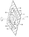
図1の軸方向の側面図には複数の例示的タービン動動翼10の1つが示されており、支持用回転ディスク12から半径方向外側に延びている。ディスクは部分的に示されており、軸方向の中心線つまり回転軸14を含み、運転中ディスクと動翼とが軸周りに回転する。
【0017】
動翼の外側部分は、一体のダブテール10bから半径方向外側に延びるエーロフォイルを形成し、ダブテールは動翼をディスク周囲の相補的な軸方向ダブテール・スロット内で半径方向に保持するよう従来の方法で形成されている。
【0018】
図1および図2に示すように、動翼エーロフォイルは、全体的に凹形の正圧側壁16と、円周方向または横方向に対向する全体的に凸形の負圧側壁18とを含む。図1に示すように、2つの側壁は、対応する一体プラットフォームにおいてエーロフォイルの内側境界を画定する根元部22から半径方向外側の先端部24まで、放射軸20に沿って長手方向に延びる。側壁は、エーロフォイル全長に沿って半径方向に延び、対応する前縁と後縁26、28との間で軸方向に翼弦方向に延びる。
【0019】
また、側壁は、前縁と後縁との間で円周方向または横方向に隔てて配置され、翼弦方向に離間して配置される複数の一体的な壁つまり隔壁30によって相互に連結されており、隔壁は、根元部と先端部との間で翼幅方向へ長手方向に延び、一般的にそこを通って流れる冷却媒体34に関する接頭記号32により識別される、対応する半径方向流路を形成する。冷却媒体は、運転中に動翼を冷却するよう従来の方法で圧縮機(図示せず)から分流される加圧空気の一部である。
【0020】
流路32は、内部対流によって動翼を冷却するために冷却媒体を流すように、あらゆる従来的な方法を用いて1つまたはそれ以上の冷却回路に形成できる。図1および図2に示す例示的な実施形態において、流路32は、翼弦中央領域の5つの通路の波状冷却回路であり、半径方向流路32a−32eの順次連続する形態で従来同様に配置されている。第1通路32aにおいて、冷却媒体は動翼の根元部から先端部へ半径方向外側へ流れ、第2通路32bにおいて、冷却媒体は翼先端部の下方で反転して先端部から根元部へ半径方向内側に流れる。この順序は第3通路32c、第4通路32dおよび第5通路32eにおいて、冷却媒体の方向で外側および内側方向へ交互に繰り返される。
【0021】
前縁冷却回路は、隣接の供給通路32gによる衝突冷却で供給される前縁流路32fを含む。また、後縁冷却回路は、隣接する供給チャネル32kによる衝突冷却で供給される後縁チャネル32hを含む。
【0022】
種々の冷却回路は如何なる従来構造でもよく、動翼は典型的に対応する流路から正圧側壁と負圧側壁とを通って延びる数列の膜冷却孔36を含み、冷却媒体はここを通って動翼の外部表面に沿って吐出され膜冷却をもたらす。
【0023】
図2に示すように、この例示的な実施形態において、動翼は相当量の捩れを有し、後縁28は、前縁26から円周方向または横方向にオフセットしており、動翼の円周方向の回転の際に前縁に先行する。図2に示すように上から見た場合、動翼の捩れは負圧側壁18と回転軸14との間の捩れ角Aで表すことができる。動翼の捩れは、従来の方法で空気力学的な理由で設けられ、ある設計において制限してもよく、図2の実施形態のような他の設計においては極めて重要である。
【0024】
動翼捩れの1つの影響は、前縁から後縁に向かって1つまたはそれ以上の流路が円周方向または横方向にオフセットされることである。図2に示す例示的な実施形態において、流路32bは僅かな部分が前縁26からオフセットし;流路32aは大部分が前縁からオフセットし;後縁チャネル32kと32hとは前縁から完全にオフセットし、この順にオフセット量が大きくなっている。
【0025】
対応して、残りの5つの通路32c、32d、32e、32g、32fは、相互に且つ前縁とほぼ軸方向へ整列している。
【0026】
それぞれの流路32は、正圧側壁および負圧側壁16、18によって円周方向に境界が定められ、その間を延びる隔壁30によって軸方向または翼弦方向に境界が定められているが、動翼の捩れを被る流路は、回転軸14に対して斜めの方向性をもっている。オフセットした4つの通路32a、b、h、kの斜めの方向性は、軸方向に整列された5つの通路32c、d、e、g、fとは対照的に内部対流冷却に著しく影響を及ぼす。
【0027】
図1に示すように、冷却媒体34はまず最初に、各々の流路を通って半径方向外側または半径方向内側のいずれかに流される。運転中に動翼10は回転軸14の周りを回転し、流路はそこを通る冷却媒体の一次流れの境界を定め、閉じこめるので、半径方向の流れは、冷却媒体流の半径方向速度と動翼の回転速度とのベクトル積の方向のコリオリの力を受ける。コリオリの力の方向は、冷却媒体の速度ベクトルに対して直交する。外側に向かう流路における冷却媒体速度ベクトルは、内側に向かう流路における速度ベクトルとは逆なので、対応するコリオリの力の方向も逆である。
【0028】
コリオリの力の影響は、上流へ流れる流路と下流に流れる流路とでは異なる各々の流路の二次の流れ場を持ち込むことである。図2に示す実質的に閉じられた流路内のコリオリの二次流れは、一対の逆回転の渦34aとして観察される。各々の流路の対のコリオリ渦は、典型的に軸方向前方と軸方向後方の渦として互いに軸方向に整列している。
【0029】
二次流れの渦は逆回転し、その回転の方向は上流への流路と下流への流路で異なる。例えば、図2に示す下流への流路32bにおいて、後方の渦は時計方向に回転し、前方の渦は反時計方向に回転する。上流への流路32cにおいて、後方の渦は反時計方向に回転し、前方の渦は時計方向に回転する。
【0030】
本発明によれば、タービュレータの性能と内部冷却とを高めてそこでの性能低下を回避するよう従来のタービュレータを別の方法で選択的に導入して、捩れた構造の動翼を補うようコリオリ渦の性質を利用できる
より詳細には、図1および図2に示すタービン動動翼中にタービュレータが配置される改良された方法は、1つまたはそれ以上の対応する列の傾斜タービュレータ38を、円周方向にオフセットした通路32a、b、h、kの少なくとも1つに配置することを含み、通路内の全ての傾斜タービュレータは、根元部22および後縁28に向けて半径方向内側に傾き、つまり傾斜しており、各々のオフセットした通路内の渦34aからのコリオリの流れと同方向にタービュレータに沿って冷却媒体を導く。
【0031】
1つの例示的なオフセットした通路32aは、図3により詳細に示されている。例示的な流路における動翼の捩れAは、前縁近傍で軸方向に整列された通路に対して流路を時計方向に捩りまたは斜めに方向づけする。図3には対のコリオリ渦34aが示されており、それらの相対位置は軸方向に前後している。上流への流路32aで反時計方向に回転する後方コリオリ渦は、図示のように右から左への流れ方向において負圧側壁18上の傾斜タービュレータと局所的に交わることに留意されたい。同様に前方コリオリ渦は、上流への流路32aで時計方向に回転して、右から左への流れ方向において正圧側壁16上の傾斜タービュレータ38と局所的に交わる。
【0032】
従って、傾斜タービュレータ38は、対応するコリオリ渦を補うよう特別に構成され傾斜されており、傾斜タービュレータはコリオリ渦の性能に直接影響を与え、一次冷却媒体流が外向きか内向きのいずれかであるオフセットした通路内の二次コリオリ流れと同じ方向であり、対応するタービュレータに沿う三次の局所的冷却媒体流34bを助長して導くようになっている。
【0033】
傾斜タービュレータ38の例示的な実施形態は、負圧側壁18に関する図4と、協働する正圧側壁16に関する図5の側面図に示されている。各々のタービュレータ38は直線状であり、軸方向に対応する前方隔壁と後方隔壁30との間を延びることが好ましく、隔壁は軸方向に流路32aの境界を定める。各々のタービュレータは、鋭角な傾斜角Bで傾斜もしくは傾いており、動翼後縁に向かうタービュレータの軸方向後方端部は、前縁に向かうタービュレータの軸方向前方端部に対して半径方向内側に位置している。各々のタービュレータ38は2つの隔壁30の間で連続していることが好ましい。別の実施形態(図示せず)において、所望のタービュレータ構造と傾斜に全体的に影響を与えるよう配列しつつ、個々のタービュレータを軸方向にセグメント化してもよい。
【0034】
図4は、負圧側壁18内の上流への冷却媒体34を示し、冷却媒体は反時計方向に回転する後方コリオリ渦をもたらし、渦は本質的に傾いたタービュータ38と協働して冷却媒体を乱し、局所的にタービュレータの流れ34bを負圧側に沿って後方コリオリ渦と略同一方向に指向する。
【0035】
同様に図5は正圧側壁16内の上流への冷却媒体34を示し、対応するコリオリ渦は時計方向に回転する。傾斜タービュレータ38は、選択的に傾いており、タービュレータの流れ34bを正圧側壁に沿って前方コリオリ渦と同方向に局所的に乱して指向する。
【0036】
図4および図5に示すように、上流への流路32a内の対向する正圧側壁および負圧側壁上の傾斜タービュレータ38の2つの列は、約30度から約60度であってもよい同じ傾斜角Bをもつことが好ましい。対向するタービュレータは、所望であれば互いに半径方向に整列していてもよく、半径方向にオフセットしていてもよい。
【0037】
また、傾斜タービュレータ38は、境界を定める隔壁30の間の流路内の対応する側壁の軸方向の範囲全体に亘って同一の傾斜をもつことが重要である。流路32aでの動翼の相当大きな捩れ角Aに起因して、後方コリオリ渦は主として負圧側壁18にのみ隣接し、前方コリオリ渦は主として正圧側壁16にのみ隣接する。
【0038】
図2に示すように、捩れ角Aは流路から流路へ動翼後縁28に向かって大きくなるので、後方コリオリ渦は負圧側壁でその影響が大きくなり、正圧側壁でその影響が小さくなり、同様に前方コリオリ渦は正圧側壁でその影響が大きくなり、負圧側壁でその影響が小さくなる。
【0039】
オフセットした流路内部の傾斜タービュレータ38と、その中で発達したコリオリ渦との好ましい配列の重要性は、図4を参照して更に明らかにできる。図示の傾斜タービュレータ38が、120−150度の傾斜角Bで反対に傾斜する場合、局所的なコリオリ渦の方向は、図示のように左側に向かわず図4の右側に向かう冷却媒体のタービュレータに沿った局所的な乱れと反対方向になる。その後、傾斜タービュレータによってもたらされる局所的な流れは、局所的なコリオリ渦の流れと反対になり、局所的な冷却媒体の速度が遅くなり、それに応じて局所的に熱伝達率が小さくなる。
【0040】
しかし、図4に示す好適な実施形態において、傾斜タービュレータは冷却媒体を局所的にコリオリ渦と同じ方向に指向し、その速度は付加的で熱伝達率が局所的に大きくなる。
【0041】
図1に示される例示的な上流への流路32aは、翼根元部22近傍の下側入口40を含み、従来の方法でダブテール10bを通して冷却媒体34を受取る。その後冷却媒体は、流路32aを通って翼先端部24に向かって外側へ導かれる。傾斜タービュレータ38は、後縁に向かって半径方向内側に傾斜しており、前述のようにコリオリ渦と選択的に協働する。
【0042】
また、図1に示される第2流蛇行流路32bは、図2に示すように大きな捩れを受けるので、そこにも傾いた傾斜タービュレータ38を備えることが好ましい。しかし、本実施形態において、流路32bは、第1通路流路32aからの冷却媒体34を半径方向内側方向に再指向する、逆曲げ形状の上側入口42を含む。上側入口42は、翼先端部24近傍に配置されており、冷却媒体を翼根元部22に向けて半径方向内側に流す。図4および図5に示すように、2つの通路32aおよび32bの同様に傾いた傾斜タービュレータ38は、この通路中に発生する対応するコリオリ渦と協働して、同様の方法で運転中の熱伝達冷却を高める。
【0043】
大きな捩れを有する最初の2つの蛇行流路32a、bを形成する対応する隔壁30には孔がないことが好ましく、これにより強力なコリオリ渦が発生し、協働する傾斜タービュレータによって補われる。また、後縁供給通路32kは大きな捩れを受け、同様に傾斜タービュレータ38を含むことができる。
【0044】
供給通路32kの後方隔壁は、小さな衝突ホールの列を含み冷却媒体を後縁流路32hにある正圧側壁内部に吐出する。隔壁孔は比較的小さく相当な圧力降下をもたらすので、供給通路32k内にコリオリ渦をそれでも発生させることができ、その中の熱伝達冷却を高めるために傾斜タービュレータを導入することができる。
【0045】
図2に示すように、後縁流路32hは、動翼の最も狭い部分に配置されるでの最も大きな動翼の捩れを受ける。制限された空間に照らして、傾斜タービュレータ38の列は、その正圧側壁内部にのみ組み込まれてもよく、その中に形成される各々のコリオリ渦と協働して冷却性を高める。通路の負圧側は、タービュレータがない平滑のままであってもよい。従って、傾斜タービュレータ38は、正圧側壁16等の後縁流路32hの動翼側壁の少なくとも1つに好都合に組み込むことができる。
【0046】
また、オフセットした流路のいずれか1つで空間的に都合がつく場所では、タービュレータ38は、正圧側壁および負圧側壁沿って同一のまたは類似の後縁に向かう半径方向内側の傾斜を有する対向する列の形態で配置されるのが好ましい。
【0047】
前述のように、傾斜タービュレータ38を、動翼の捩れに起因して動翼前縁から横方向または円周方向のオフセットを受ける流路にのみ導入するのが好ましい。例えば、動翼捩れ角Aが約45度を超え、対応するオフセットした流路の正圧側壁16と該壁上のタービュレータの大部分を同一通路の対向する負圧側壁18よりも動翼前縁26に近づけて配置する場合に傾斜タービュレータ38は好適である。このことは、図2において4つのオフセットした流路32a、b、h、kに関して示されており、ここでは正圧側壁は、この通路の対応する負圧側壁の位置から様々な大きさだけ軸方向の前方に位置している。
【0048】
図2において3つの流路32a、b、kに示すように、そこにおける対向する正圧側壁および負圧側壁内側の対応する傾斜タービュレータ38は、軸方向に中央で互いにオーバーラップし、負圧側壁上のタービュレータは中央のオーバーラップから後縁28に向かって後方へ延び、正圧側壁上のタービュレータは中央のオーバーラップから前縁26に向かって前方に延びる。図示の例示的な実施形態において、各々のオフセットした流路の対向するタービュレータの軸方向のオーバーラップ量は、動翼の捩れ角が最大捩れ角約70度まで大きくなるにつれて減少する。
【0049】
図2は、それ相応に大きな動翼の捩れに起因して大きくなった最も後方の流路の歪みまたは曲がりを明確に示している。それでもやはり対応する流路の半径方向の断面は略四辺形であり、対応する対のコリオリ渦は運転中にそこに形成され、その中で軸方向で前後方向に位置する。動翼の捩れと、このことがコリオリ渦と協働することの重要性は、目に見えるほどの横方向オフセットまたは捩れをもたない軸方向に整列された最も前方の流路を調べると更に明らかになる。
【0050】
図2に示すオフセットした流路については傾斜タービュレータ38のみが望ましいが、顕著な動翼の捩れなく動翼前縁26と軸方向へ整列される1つまたはそれ以上の流路32c、d、e、g中には、タービュレータ・シェブロン44のみの対応する列を配置することが更に望ましい。軸方向へ整列される流路は、前縁と整列してオフセットした流路の前方に配置され、これは各々の正圧側壁および負圧側壁を、配列された各々の通路内のコリオリ渦にさらす。
【0051】
図4および図5には、第3の蛇行通路、上流への流路32cに関する、例示的なタービュレータ・シェブロン44の列がより詳細に示されている。各々のタービュレータ・シェブロン44は、対向する障壁から、冷却媒体が流れることができる各リブの共通の尾筒部の形態の頂点へ収束しまたは向かう一対のリブを含んでいる。このタービュレータ・シェブロンは、従来と同様のものであり、Leeによる米国特許第5,797,726号に詳細に説明されており、その全ては本明細書に参照文献として組み込まれている。
【0052】
シェブロン44は、正圧側壁および負圧側壁16,18に沿って、通路32c等の軸方向に整列された1つまたはそれ以上の流路内に配置され、冷却媒体をシェブロンに沿って流路内のコリオリ渦と同じ方向に局所的に指向する。
【0053】
図2に示すように、タービュレータ・シェブロン44は、流路32c内で両側壁に配置され、負圧側壁18上のシェブロンは、図4に示すように先端部に向かって半径方向外側方向に先細になり;正圧側壁16上のシェブロンは、図5に示すように根元部に向かって半径方向内側方向に先細になる。
【0054】
最初に図2に示したように、両側壁のタービュレータ・シェブロンは、流路32c中の発達した前方および後方のコリオリ渦の一方と相応に協働する。反時計方向の後方渦は、同じ方向の流れ成分を得るために負圧側シェブロンの右半分と協働し、同様に、正圧側シェブロンの右半分と協働する。同様に、時計方向前部コリオリ渦は、同じ方向の冷却媒体の流れ成分を得るために正圧側壁および負圧側壁上の左半分のシェブロンと協働する。
【0055】
軸方向に整列される前方流路32c、d、e、gの方向が、横方向にオフセットした後部流路32a、b、h、kに対して異なることに照らして、そこではタービュレータ・シェブロンまたは傾斜タービュレータのいずれかが使用されるが、その逆はない。軸方向に整列した前方流路の前方および後方コリオリ渦は、動翼の正圧側壁および負圧側壁に同様に影響を及ぼすので、タービュレータ・シェブロン44は単独で、タービュレータとコリオリ渦との間で不都合な流れのよどみを生じることなく熱伝達を最大にするのに好適である。
【0056】
従って、オフセットした流路の傾斜タービュレータは、その共通の傾斜が後方コリオリ渦で流れを助長するが、前方コリオリ渦で流れを弱めるので、軸方向に整列された前方通路においては特に使用しない。2つのコリオリ渦は、前方通路では正圧側壁および負圧側壁の各々の異なる局所的方向に作用するので、単一に傾斜した傾斜タービュレータは、前方通路のコリオリ渦を補わず、熱伝達冷却能力を最大にできない。
これに対応して、前方流路のタービュレータ・シェブロン44は、同じ理由から、後方、横方向にオフセットした流路で使用しないことが好ましい。後方コリオリ渦は、負圧側壁に最大の影響を与えるが正圧側壁には殆ど影響を与えず、前方コリオリ渦は、正圧側壁に最大の影響を与えるが負圧側壁には殆ど影響を与えないので、後方通路においては単一に傾斜した傾斜タービュレータ38のみが好ましい。オフセットした後方通路にタービュレータ・シェブロンを使用してもコリオリ渦の熱伝達性能を最大にできない。
【0057】
例えば、後方コリオリ渦が負圧側シェブロンの右半分を補っても、シェブロンの左半分の部分の性能が低下する。同様に、前方コリオリ渦が正圧側シェブロンの左半分を補っても、その右半分の部分の性能が低下することになる。
【0058】
【発明の効果】
従って、円周方向にオフセットした流路の傾斜タービュレータと、軸方向に整列された流路のタービュレータ・シェブロンとを選択的に使用することによって、そこで発生する対応するコリオリ渦の最大性能の利点を得ることができる。つまり、傾斜タービュレータとシェブロンは、コリオリの力が引き起こす二次的な流れ循環を有する、上流への流路と下流への流路を通る冷却媒体の主流れ方向に合致する構成に特に調整される。
【0059】
運転中に発生するコリオリ渦は、各々のタービュレータと協働して局所的な冷却媒体を通路の内壁に沿って連続的に循環させ、そこでの熱伝達を高める。各々のタービュレータに沿ってコリオリ渦を確実に局所的な流れと同じ方向に流すこによって、流れのよどみが低減し除去されて熱伝達冷却能力が最大になり、個々の流路の捩れや湾曲と無関係にコリオリ渦を局所的に補うことができる。
【0060】
本発明の好適かつ例示的な実施形態であると考えられるものを説明したが、当業者には、以上の説明から本発明の他の変更を容易に考えることができる。従って、本発明の真の精神と範囲内にあるこのような全ての変更は特許請求の範囲において保護されることを求めるものである。
【図面の簡単な説明】
【図1】本発明の例示的実施形態による、支持用ロータディスク中に取り付けられたタービン動動翼の軸方向の部分断面側面図である。
【図2】図1に示す動翼の線2−2に沿う半径方向の断面図である。
【図3】図2の標示3の一点鎖線円内に示す円周方向にオフセットした半径方向流路の拡大図である。
【図4】図2に示す動翼の線4−4に沿う負圧側壁内部の拡大断面側面図である。
【図5】図2に示す動翼の正圧側壁内部の線5−5に沿う拡大断面図である。
【符号の説明】
10 動翼
12 ディスク
14 軸線
16 正圧側壁
18 負圧側壁
20 半径方向軸
22 根元部
24 先端部
26 前縁
28 後縁
30 隔壁
32 流路
34 冷却媒体
36 孔
38 傾斜タービュレータ
40 入口
42 入口
44 シェブロン[0001]
BACKGROUND OF THE INVENTION
The present invention relates generally to gas turbine engines, and more particularly to turbine blades used in such engines.
[0002]
[Prior art]
In a gas turbine engine, air is pressurized by a compressor and then mixed with fuel in a combustor and ignited to generate hot combustion gases. The gas is directed to a turbine to extract energy and generate useful work such as powering a compressor and powering a fan to propel an aircraft in flight.
[0003]
The high pressure turbine includes a stationary turbine nozzle that initially receives combustion gases from the combustor and follows a turbine blade cascade extending radially outward from a support disk. The nozzle includes an airfoil and vane that directs combustion gases to cooperating airfoil blades.
[0004]
The vanes and blades are hollow and contain various cooling circuits in which air is diverted from the compressor and used as a cooling medium to thermally protect the vanes and blades. The cooling method of the stationary blade and the moving blade is extremely complicated due to various cooling requirements around the airfoil between the root portion and the tip portion and between the leading edge and the trailing edge.
[0005]
Typically, an airfoil is a number of axially spaced axially extending radially along the airfoil spans to separately cool the leading, central chord and trailing edge regions of the airfoil. Including a cooling circuit.
[0006]
The cooling medium directed through the cooling circuit removes heat in the airfoil by heat transfer convection, and typically the cooling medium flows through the airfoil pressure and suction side walls and on the airfoil outer surface. It is discharged through a film cooling hole that insulates the outer surface against high-temperature combustion gas.
[0007]
Internal heat transfer can be enhanced by providing pins or straight ribs along the airfoil sidewalls that form turbulators that disrupt the coolant flow and locally increase heat transfer. The turbulator has various shapes and directions orthogonal to the refrigerant flow direction, and is further inclined according to the requirements for individual cooling medium passages of different circuits.
[0008]
As the turbine blades rotate during operation, this cooling is further complicated by the rotational force applied to the cooling medium. For example, the Coriolis force acts on the cooling medium flowing through the blades and affects its cooling capacity. In a typical radially extending cooling passage, the main direction of the main cooling medium therethrough is directed radially outward from the blade root to the tip as seen in a typical multi-flow wave cooling circuit. Either from the tip of the blade to the root, or radially inward.
[0009]
A typical linear turbulator is oriented along the airfoil chord and may be substantially orthogonal to or inclined with respect to the radial direction of the cooling medium flow, correspondingly. Delivers different performance. However, in both cases, the turbulator is effective and moves the cooling medium locally along the airfoil inner surface to enhance heat transfer.
[0010]
However, the Coriolis force affects the cooling performance of the turbulator. The Coriolis force is based on the vector product of the radial velocity of the refrigerant flow in the outward or inward direction through each radial flow path and the blade rotation speed about the axial centerline axis of the rotor disk. The medium acts in a direction perpendicular to the radial flow of the refrigerant. Accordingly, the Coriolis force acting on the cooling medium acts in the opposite direction between the flow path in the inner direction and the flow path in the outer direction.
[0011]
However, in both examples, the Coriolis force is effective to generate a pair of Coriolis vortices, which in each radial flow path is a secondary flow field relative to the radially directed cooling medium primary flow field. As a reverse rotation. Accordingly, each passage grows a corresponding axially forward Coriolis vortex and axially rearward Coriolis vortex, and rotates counterclockwise in different rotational directions in the inner and outer passages of the flow path.
[0012]
US Pat. No. 5,797,726 to Lee discloses a turbulator pair, also called a chevron, that works with Coriolis vortices to enhance heat transfer cooling inside a turbine blade. The chevron is oriented differently along the pressure and suction side walls of the blade, cooperating with a pair of Coriolis vortices in each cooling passage, and in the same direction as the adjacent Coriolis vortices, but not in the opposite direction The cooling medium is directed locally along the chevron. In this way, local tertiary flow effects in the chevron itself are added rather than subtracted from the secondary Coriolis vortices, preventing flow stagnation and increasing heat transfer cooling inside the blade.
[0013]
[Problems to be solved by the invention]
In view of the complexity of turbine airfoils and the directional effects of Coriolis forces, further improvements in turbine blade turbulator design are desired.
[0014]
[Means for Solving the Problems]
A method of placing a turbulator on a turbine blade includes placing a tilted turbulator in a radial flow path circumferentially offset from the blade leading edge. All the inclined turbulators are inclined radially inward toward the trailing edge of the rotor blade and direct the cooling medium in the same direction as the Coriolis flow inside the passage offset along the turbulator. In certain embodiments, the turbulator chevron is also disposed in a radial flow path that is axially aligned with the blade leading edge and matches the Coriolis flow therein.
[0015]
DETAILED DESCRIPTION OF THE INVENTION
Preferred and exemplary embodiments of the invention and other objects and advantages will be more particularly described in the following detailed description taken in conjunction with the accompanying drawings.
[0016]
The axial side view of FIG. 1 shows one of a plurality of
[0017]
The outer portion of the blade forms an airfoil extending radially outward from the
[0018]
As shown in FIGS. 1 and 2, the blade airfoil includes a generally concave
[0019]
The side walls are arranged circumferentially or laterally between the leading edge and the trailing edge, and are connected to each other by a plurality of integral walls or
[0020]
The flow path 32 can be formed into one or more cooling circuits using any conventional method to flow a cooling medium to cool the blades by internal convection. In the exemplary embodiment shown in FIGS. 1 and 2, the flow path 32 is a five-passage wave cooling circuit in the central region of the chord, as in the prior art in the form of a sequential series of radial flow paths 32a-32e. Has been placed. In the first passage 32a, the cooling medium flows radially outward from the root portion of the rotor blade to the tip portion, and in the
[0021]
The leading edge cooling circuit includes a leading
[0022]
The various cooling circuits may be of any conventional construction, and the blade typically includes a series of membrane cooling holes 36 extending from corresponding flow paths through the pressure and suction sidewalls through which the cooling medium passes. It is discharged along the outer surface of the rotor blade, resulting in film cooling.
[0023]
As shown in FIG. 2, in this exemplary embodiment, the blade has a substantial amount of twist, and the trailing
[0024]
One effect of blade twist is that one or more flow paths are offset circumferentially or laterally from the leading edge to the trailing edge. In the exemplary embodiment shown in FIG. 2,
[0025]
Correspondingly, the remaining five
[0026]
Each flow path 32 is delimited in the circumferential direction by a pressure side wall and a
[0027]
As shown in FIG. 1, the cooling
[0028]
The effect of the Coriolis force is to bring in a secondary flow field for each channel that is different between the upstream flow channel and the downstream flow channel. The secondary Coriolis flow in the substantially closed channel shown in FIG. 2 is observed as a pair of
[0029]
The secondary flow vortex rotates in the reverse direction, and the direction of rotation differs between the upstream flow path and the downstream flow path. For example, in the
[0030]
According to the present invention, the conventional turbulator is selectively introduced in another way to enhance the performance and internal cooling of the turbulator and avoid the performance degradation there, so that the Coriolis vortex is supplemented to compensate for the rotor blade having a twisted structure. Can take advantage of the nature of
More particularly, the improved method of placing turbulators in the turbine blade shown in FIGS. 1 and 2 offset one or more corresponding rows of
[0031]
One exemplary offset passage 32a is shown in greater detail in FIG. The blade twist A in the exemplary flow path twists or obliquely turns the flow path clockwise relative to the axially aligned passageway near the leading edge. FIG. 3 shows a pair of
[0032]
Thus, the
[0033]
An exemplary embodiment of the
[0034]
FIG. 4 shows the
[0035]
Similarly, FIG. 5 shows the
[0036]
As shown in FIGS. 4 and 5, the two rows of inclined pressure turbulators 38 on the opposing pressure and suction side walls in the upstream flow path 32a may be about 30 degrees to about 60 degrees. It is preferable to have the same inclination angle B. Opposing turbulators may be radially aligned with each other and offset in the radial direction if desired.
[0037]
It is also important that the
[0038]
As shown in FIG. 2, the twist angle A increases from the flow path to the flow path toward the trailing
[0039]
The importance of the preferred arrangement of the
[0040]
However, in the preferred embodiment shown in FIG. 4, the inclined turbulator directs the cooling medium locally in the same direction as the Coriolis vortex, with an additional speed and locally increased heat transfer coefficient.
[0041]
The exemplary upstream flow path 32a shown in FIG. 1 includes a
[0042]
Moreover, since the 2nd flow meandering
[0043]
The corresponding
[0044]
The rear partition wall of the
[0045]
As shown in FIG. 2, the trailing
[0046]
Also, where it is spatially convenient in any one of the offset channels, the
[0047]
As described above, it is preferable to introduce the
[0048]
As shown in the three flow paths 32a, b, k in FIG. 2, the corresponding
[0049]
FIG. 2 clearly shows the distortion or bending of the rearmost flow path that is increased due to the correspondingly large rotor blade twist. Nevertheless, the corresponding channel cross section in the radial direction is substantially quadrilateral, and a corresponding pair of Coriolis vortices are formed there during operation, in which it lies axially in the longitudinal direction. The importance of the blade twist and this in cooperation with the Coriolis vortex is further demonstrated by examining the axially aligned foremost flow path with no appreciable lateral offset or twist. It becomes clear.
[0050]
Only the tilted
[0051]
4 and 5 show in greater detail an
[0052]
The
[0053]
As shown in FIG. 2, the
[0054]
Initially, as shown in FIG. 2, the turbulator chevrons on the side walls cooperate correspondingly with one of the developed front and rear Coriolis vortices in the
[0055]
In light of the fact that the direction of the axially aligned
[0056]
Thus, the inclined channel turbulators with offset channels are not particularly used in axially aligned forward passages because their common slope facilitates flow with the rear Coriolis vortex but weakens the flow with the front Coriolis vortex. Since the two Coriolis vortices act in different local directions on each of the pressure and suction side walls in the forward passage, a single inclined inclined turbulator does not compensate for the Coriolis vortices in the forward passage and heat transfer cooling capacity Cannot be maximized.
Correspondingly, the
[0057]
For example, even if the rear Coriolis vortex supplements the right half of the suction side chevron, the performance of the left half of the chevron deteriorates. Similarly, even if the front Coriolis vortex supplements the left half of the pressure side chevron, the performance of the right half of the pressure will decrease.
[0058]
【The invention's effect】
Therefore, the selective use of circumferentially offset channel tilt turbulators and axially aligned channel turbulator chevrons can provide the maximum performance advantage of the corresponding Coriolis vortices generated there. Obtainable. In other words, the inclined turbulator and chevron are specifically adjusted to a configuration that matches the main flow direction of the cooling medium through the upstream flow path and the downstream flow path, with secondary flow circulation caused by Coriolis forces. .
[0059]
The Coriolis vortex generated during operation cooperates with each turbulator to continuously circulate a local cooling medium along the inner wall of the passage and enhance heat transfer there. By ensuring that Coriolis vortices flow along each turbulator in the same direction as the local flow, flow stagnation is reduced and eliminated, maximizing heat transfer cooling capacity, and individual channel twisting and bending. Irrespective of Coriolis vortices can be supplemented locally.
[0060]
Although what has been considered to be preferred and exemplary embodiments of the present invention has been described, other modifications of the present invention can be readily devised by those skilled in the art from the foregoing description. Accordingly, it is sought that all such modifications within the true spirit and scope of the invention be protected by the following claims.
[Brief description of the drawings]
FIG. 1 is an axial partial cross-sectional side view of a turbine blade mounted in a supporting rotor disk in accordance with an exemplary embodiment of the present invention.
2 is a radial cross-sectional view taken along line 2-2 of the rotor blade shown in FIG. 1. FIG.
FIG. 3 is an enlarged view of a radial flow path offset in the circumferential direction shown in a one-dot chain line circle of a
4 is an enlarged cross-sectional side view of the inside of a suction side wall taken along line 4-4 of the rotor blade shown in FIG. 2;
5 is an enlarged cross-sectional view taken along line 5-5 inside the pressure side wall of the rotor blade shown in FIG.
[Explanation of symbols]
10 Moving blade
12 discs
14 axis
16 Positive pressure side wall
18 Negative pressure side wall
20 radial axis
22 Root
24 Tip
26 Leading edge
28 trailing edge
30 Bulkhead
32 channels
34 Cooling medium
36 holes
38 inclined turbulators
40 entrance
42 entrance
44 Chevron
Claims (5)
根元部(22)から先端部(24)へ翼長方向へ延び、前縁および後縁(26、28)の間で翼弦方向へ延びる正圧側壁および負圧側壁(16、18);
を備え、
前記側壁は、前記前縁および後縁の間で翼幅方向に離間して配置され、冷却媒体(34)を流すために流路(32)を形成するよう、前記根元部と先端部との間で翼長方向に延び且つ翼弦方向に離間する複数の隔壁(30)により相互に連結され;
前記動翼の前記流路は、前記正圧側壁(16)が、前記流路における対向する負圧側壁(18)よりも前記前縁(26)に軸方向において近い部分を多く有し、前記流路が前記前縁(26)から前記後縁(28)に向かって翼幅方向にオフセットするよう捩れを有するオフセット流路(32a、b、h、k)を含み、前記オフセット流路の少なくとも1つは、翼長方向に離間し、冷却媒体をタービュレータに沿って前記オフセット流路内のコリオリの流れと同一方向に指向させるために、全て前記後縁(28)に向かって前記根元部(22)の方向へ傾いており且つ前記隔壁(30)間で連続している傾斜タービュレータ(38)の列を有し;
前記タービュレータ(38)は、前記隔壁(30)間で直線状に延び、
前記タービュレータ(38)は、前記正圧側壁および負圧側壁(16、18)の両方に沿って前記オフセット流路(32a、b、k)の内側に配置され、
前記流路(32)は、前記オフセット流路の前方に配置され、前記前縁(26)に整列された別の流路(32c、d、e、g)を更に備え、
前記整列された流路(32c、d、e、g)は、前記正圧側壁および負圧側壁(16、18)に沿って前記整列された流路内に配置された、前記タービュレータの対からなるシェブロン(44)の列を備え、
前記タービュレータの対からなるシェブロン(44)の列は、前記先端部(24)に向かって半径方向外側へ先細となる正圧側シェブロンの列と、前記根元部(22)に向かって半径方向内側へ先細となる負圧側シェブロンの列と含む
ことを特徴とするタービン動翼(10)。A turbine blade (10),
Pressure and suction side walls (16, 18) extending lengthwise from the root (22) to the tip (24) and extending in the chord direction between the leading and trailing edges (26, 28);
With
The side wall is spaced apart in the span direction between the leading edge and the trailing edge, and is formed between the root and the tip so as to form a flow path (32) for flowing the cooling medium (34). Interconnected by a plurality of partition walls (30) extending in the blade length direction and spaced apart in the chord direction between them;
The flow path of the blade has a portion where the pressure side wall (16) is closer to the front edge (26) in the axial direction than the opposing pressure side wall (18) in the flow path, The flow path includes an offset flow path (32a, b, h, k) having a twist so as to be offset in the span direction from the leading edge (26) toward the rear edge (28), and at least the offset flow path One is spaced apart in the wing length direction, and in order to direct the cooling medium along the turbulator in the same direction as the Coriolis flow in the offset flow path, the root ( have a sequence of consecutive and slant turbulators (38) between and the partition walls are inclined in the direction (30) of 22);
The turbulator (38) extends linearly between the partition walls (30),
The turbulator (38) is disposed inside the offset flow path (32a, b, k) along both the pressure side wall and the suction side wall (16, 18),
The flow path (32) further includes another flow path (32c, d, e, g) disposed in front of the offset flow path and aligned with the leading edge (26),
The aligned flow paths (32c, d, e, g) are from the turbulator pair disposed in the aligned flow paths along the pressure and suction side walls (16, 18). With a row of chevrons (44)
A row of chevrons (44) comprising the pair of turbulators is a row of pressure side chevrons that taper radially outward toward the tip (24) and radially inward toward the root (22). A turbine rotor blade (10) comprising a suction side chevron array that tapers .
Applications Claiming Priority (2)
| Application Number | Priority Date | Filing Date | Title |
|---|---|---|---|
| US09/466,155 US6331098B1 (en) | 1999-12-18 | 1999-12-18 | Coriolis turbulator blade |
| US09/466155 | 1999-12-18 |
Publications (3)
| Publication Number | Publication Date |
|---|---|
| JP2001234702A JP2001234702A (en) | 2001-08-31 |
| JP2001234702A5 JP2001234702A5 (en) | 2011-04-28 |
| JP4739509B2 true JP4739509B2 (en) | 2011-08-03 |
Family
ID=23850721
Family Applications (1)
| Application Number | Title | Priority Date | Filing Date |
|---|---|---|---|
| JP2000381145A Expired - Fee Related JP4739509B2 (en) | 1999-12-18 | 2000-12-15 | Coriolis turbulator blade |
Country Status (4)
| Country | Link |
|---|---|
| US (1) | US6331098B1 (en) |
| EP (1) | EP1111190B1 (en) |
| JP (1) | JP4739509B2 (en) |
| DE (1) | DE60027679T2 (en) |
Families Citing this family (68)
| Publication number | Priority date | Publication date | Assignee | Title |
|---|---|---|---|---|
| US6474947B1 (en) * | 1998-03-13 | 2002-11-05 | Mitsubishi Heavy Industries, Ltd. | Film cooling hole construction in gas turbine moving-vanes |
| US6511762B1 (en) * | 2000-11-06 | 2003-01-28 | General Electric Company | Multi-layer thermal barrier coating with transpiration cooling |
| US6910620B2 (en) * | 2002-10-15 | 2005-06-28 | General Electric Company | Method for providing turbulation on the inner surface of holes in an article, and related articles |
| US6932573B2 (en) | 2003-04-30 | 2005-08-23 | Siemens Westinghouse Power Corporation | Turbine blade having a vortex forming cooling system for a trailing edge |
| US6955525B2 (en) * | 2003-08-08 | 2005-10-18 | Siemens Westinghouse Power Corporation | Cooling system for an outer wall of a turbine blade |
| US7186084B2 (en) * | 2003-11-19 | 2007-03-06 | General Electric Company | Hot gas path component with mesh and dimpled cooling |
| US6984102B2 (en) | 2003-11-19 | 2006-01-10 | General Electric Company | Hot gas path component with mesh and turbulated cooling |
| US7114923B2 (en) * | 2004-06-17 | 2006-10-03 | Siemens Power Generation, Inc. | Cooling system for a showerhead of a turbine blade |
| DE502004003477D1 (en) * | 2004-07-05 | 2007-05-24 | Siemens Ag | Film-cooled turbine blade |
| US7094031B2 (en) * | 2004-09-09 | 2006-08-22 | General Electric Company | Offset Coriolis turbulator blade |
| US7128533B2 (en) * | 2004-09-10 | 2006-10-31 | Siemens Power Generation, Inc. | Vortex cooling system for a turbine blade |
| US7156620B2 (en) * | 2004-12-21 | 2007-01-02 | Pratt & Whitney Canada Corp. | Internally cooled gas turbine airfoil and method |
| US7156619B2 (en) * | 2004-12-21 | 2007-01-02 | Pratt & Whitney Canada Corp. | Internally cooled gas turbine airfoil and method |
| US7189060B2 (en) * | 2005-01-07 | 2007-03-13 | Siemens Power Generation, Inc. | Cooling system including mini channels within a turbine blade of a turbine engine |
| US7435053B2 (en) * | 2005-03-29 | 2008-10-14 | Siemens Power Generation, Inc. | Turbine blade cooling system having multiple serpentine trailing edge cooling channels |
| US7534089B2 (en) | 2006-07-18 | 2009-05-19 | Siemens Energy, Inc. | Turbine airfoil with near wall multi-serpentine cooling channels |
| US7549844B2 (en) * | 2006-08-24 | 2009-06-23 | Siemens Energy, Inc. | Turbine airfoil cooling system with bifurcated and recessed trailing edge exhaust channels |
| US7637720B1 (en) | 2006-11-16 | 2009-12-29 | Florida Turbine Technologies, Inc. | Turbulator for a turbine airfoil cooling passage |
| US7914257B1 (en) | 2007-01-17 | 2011-03-29 | Florida Turbine Technologies, Inc. | Turbine rotor blade with spiral and serpentine flow cooling circuit |
| US8083485B2 (en) * | 2007-08-15 | 2011-12-27 | United Technologies Corporation | Angled tripped airfoil peanut cavity |
| US8366383B2 (en) * | 2007-11-13 | 2013-02-05 | United Technologies Corporation | Air sealing element |
| US7988410B1 (en) * | 2007-11-19 | 2011-08-02 | Florida Turbine Technologies, Inc. | Blade tip shroud with circular grooves |
| US8210814B2 (en) * | 2008-06-18 | 2012-07-03 | General Electric Company | Crossflow turbine airfoil |
| US8303252B2 (en) * | 2008-10-16 | 2012-11-06 | United Technologies Corporation | Airfoil with cooling passage providing variable heat transfer rate |
| US8167558B2 (en) * | 2009-01-19 | 2012-05-01 | Siemens Energy, Inc. | Modular serpentine cooling systems for turbine engine components |
| US8079813B2 (en) * | 2009-01-19 | 2011-12-20 | Siemens Energy, Inc. | Turbine blade with multiple trailing edge cooling slots |
| US8894367B2 (en) * | 2009-08-06 | 2014-11-25 | Siemens Energy, Inc. | Compound cooling flow turbulator for turbine component |
| US8920122B2 (en) | 2012-03-12 | 2014-12-30 | Siemens Energy, Inc. | Turbine airfoil with an internal cooling system having vortex forming turbulators |
| US9388700B2 (en) * | 2012-03-16 | 2016-07-12 | United Technologies Corporation | Gas turbine engine airfoil cooling circuit |
| US8876475B1 (en) * | 2012-04-27 | 2014-11-04 | Florida Turbine Technologies, Inc. | Turbine blade with radial cooling passage having continuous discrete turbulence air mixers |
| US9157329B2 (en) * | 2012-08-22 | 2015-10-13 | United Technologies Corporation | Gas turbine engine airfoil internal cooling features |
| US9995148B2 (en) | 2012-10-04 | 2018-06-12 | General Electric Company | Method and apparatus for cooling gas turbine and rotor blades |
| US8920123B2 (en) * | 2012-12-14 | 2014-12-30 | Siemens Aktiengesellschaft | Turbine blade with integrated serpentine and axial tip cooling circuits |
| EP2954168B1 (en) | 2013-02-05 | 2019-07-03 | United Technologies Corporation | Gas turbine engine component having curved turbulator |
| US9850762B2 (en) | 2013-03-13 | 2017-12-26 | General Electric Company | Dust mitigation for turbine blade tip turns |
| WO2014150681A1 (en) | 2013-03-15 | 2014-09-25 | United Technologies Corporation | Gas turbine engine component having shaped pedestals |
| US8985949B2 (en) * | 2013-04-29 | 2015-03-24 | Siemens Aktiengesellschaft | Cooling system including wavy cooling chamber in a trailing edge portion of an airfoil assembly |
| US9091495B2 (en) | 2013-05-14 | 2015-07-28 | Siemens Aktiengesellschaft | Cooling passage including turbulator system in a turbine engine component |
| US9500093B2 (en) * | 2013-09-26 | 2016-11-22 | Pratt & Whitney Canada Corp. | Internally cooled airfoil |
| FR3020402B1 (en) * | 2014-04-24 | 2019-06-14 | Safran Aircraft Engines | DRAWER FOR TURBOMACHINE TURBINE COMPRISING AN IMPROVED HOMOGENEITY COOLING CIRCUIT |
| US10422235B2 (en) | 2014-05-29 | 2019-09-24 | General Electric Company | Angled impingement inserts with cooling features |
| US10364684B2 (en) | 2014-05-29 | 2019-07-30 | General Electric Company | Fastback vorticor pin |
| US10563514B2 (en) | 2014-05-29 | 2020-02-18 | General Electric Company | Fastback turbulator |
| US9957816B2 (en) | 2014-05-29 | 2018-05-01 | General Electric Company | Angled impingement insert |
| US10690055B2 (en) | 2014-05-29 | 2020-06-23 | General Electric Company | Engine components with impingement cooling features |
| WO2016043742A1 (en) | 2014-09-18 | 2016-03-24 | Siemens Aktiengesellschaft | Gas turbine airfoil including integrated leading edge and tip cooling fluid passage and core structure used for forming such an airfoil |
| US10233775B2 (en) | 2014-10-31 | 2019-03-19 | General Electric Company | Engine component for a gas turbine engine |
| US10280785B2 (en) | 2014-10-31 | 2019-05-07 | General Electric Company | Shroud assembly for a turbine engine |
| US10605094B2 (en) | 2015-01-21 | 2020-03-31 | United Technologies Corporation | Internal cooling cavity with trip strips |
| US10156157B2 (en) * | 2015-02-13 | 2018-12-18 | United Technologies Corporation | S-shaped trip strips in internally cooled components |
| WO2016160029A1 (en) | 2015-04-03 | 2016-10-06 | Siemens Aktiengesellschaft | Turbine blade trailing edge with low flow framing channel |
| US9995146B2 (en) * | 2015-04-29 | 2018-06-12 | General Electric Company | Turbine airfoil turbulator arrangement |
| US10830051B2 (en) * | 2015-12-11 | 2020-11-10 | General Electric Company | Engine component with film cooling |
| US20170175532A1 (en) * | 2015-12-21 | 2017-06-22 | United Technologies Corporation | Angled heat transfer pedestal |
| WO2017171763A1 (en) * | 2016-03-31 | 2017-10-05 | Siemens Aktiengesellschaft | Turbine airfoil with turbulating feature on a cold wall |
| US10208604B2 (en) * | 2016-04-27 | 2019-02-19 | United Technologies Corporation | Cooling features with three dimensional chevron geometry |
| US10502068B2 (en) | 2016-12-02 | 2019-12-10 | General Electric Company | Engine with chevron pin bank |
| US11149555B2 (en) | 2017-06-14 | 2021-10-19 | General Electric Company | Turbine engine component with deflector |
| US10801724B2 (en) | 2017-06-14 | 2020-10-13 | General Electric Company | Method and apparatus for minimizing cross-flow across an engine cooling hole |
| US10590778B2 (en) | 2017-08-03 | 2020-03-17 | General Electric Company | Engine component with non-uniform chevron pins |
| US10577944B2 (en) | 2017-08-03 | 2020-03-03 | General Electric Company | Engine component with hollow turbulators |
| US11408302B2 (en) * | 2017-10-13 | 2022-08-09 | Raytheon Technologies Corporation | Film cooling hole arrangement for gas turbine engine component |
| US10787932B2 (en) * | 2018-07-13 | 2020-09-29 | Honeywell International Inc. | Turbine blade with dust tolerant cooling system |
| EP3803057B1 (en) * | 2018-07-13 | 2022-11-16 | Siemens Energy Global GmbH & Co. KG | Airfoil for a turbine engine incorporating pins |
| KR102161765B1 (en) * | 2019-02-22 | 2020-10-05 | 두산중공업 주식회사 | Airfoil for turbine, turbine including the same |
| CN111648830B (en) * | 2020-05-14 | 2021-04-20 | 西安交通大学 | Internal cooling ribbed channel for rear part of turbine moving blade |
| CN114215609B (en) * | 2021-12-30 | 2023-07-04 | 华中科技大学 | Blade internal cooling channel capable of enhancing cooling and application thereof |
| JP2023165485A (en) * | 2022-05-06 | 2023-11-16 | 三菱重工業株式会社 | Turbine blade and gas turbine |
Citations (6)
| Publication number | Priority date | Publication date | Assignee | Title |
|---|---|---|---|---|
| JPS4865313A (en) * | 1971-12-14 | 1973-09-08 | ||
| JPH05340201A (en) * | 1992-03-05 | 1993-12-21 | Westinghouse Electric Corp <We> | Tapered twisted rotating blade and arrangement in turbine |
| US5700132A (en) * | 1991-12-17 | 1997-12-23 | General Electric Company | Turbine blade having opposing wall turbulators |
| JPH10266803A (en) * | 1997-03-25 | 1998-10-06 | Mitsubishi Heavy Ind Ltd | Gas turbine cooling moving blade |
| JPH10274002A (en) * | 1997-01-03 | 1998-10-13 | General Electric Co <Ge> | Turbulence unit structure of cooling passage of moving blade for gas turbine engine |
| JPH10280905A (en) * | 1997-04-02 | 1998-10-20 | Mitsubishi Heavy Ind Ltd | Turbulator for gas turbine cooling blade |
Family Cites Families (17)
| Publication number | Priority date | Publication date | Assignee | Title |
|---|---|---|---|---|
| US4416585A (en) | 1980-01-17 | 1983-11-22 | Pratt & Whitney Aircraft Of Canada Limited | Blade cooling for gas turbine engine |
| US4775296A (en) | 1981-12-28 | 1988-10-04 | United Technologies Corporation | Coolable airfoil for a rotary machine |
| US4474532A (en) | 1981-12-28 | 1984-10-02 | United Technologies Corporation | Coolable airfoil for a rotary machine |
| US4515626A (en) | 1982-10-06 | 1985-05-07 | Ciba Geigy Corporation | N-(Cyclopropyl-triazinyl-n'-(arylsulfonyl) ureas having herbicidal activity |
| US4514144A (en) | 1983-06-20 | 1985-04-30 | General Electric Company | Angled turbulence promoter |
| JPS60101202A (en) * | 1983-06-20 | 1985-06-05 | ゼネラル・エレクトリツク・カンパニイ | Turblence flow promoting apparatus having angle |
| US5052889A (en) | 1990-05-17 | 1991-10-01 | Pratt & Whintey Canada | Offset ribs for heat transfer surface |
| JP3006174B2 (en) | 1991-07-04 | 2000-02-07 | 株式会社日立製作所 | Member having a cooling passage inside |
| US5681144A (en) | 1991-12-17 | 1997-10-28 | General Electric Company | Turbine blade having offset turbulators |
| US5403157A (en) | 1993-12-08 | 1995-04-04 | United Technologies Corporation | Heat exchange means for obtaining temperature gradient balance |
| US5536143A (en) * | 1995-03-31 | 1996-07-16 | General Electric Co. | Closed circuit steam cooled bucket |
| US5842829A (en) * | 1996-09-26 | 1998-12-01 | General Electric Co. | Cooling circuits for trailing edge cavities in airfoils |
| JPH10306701A (en) * | 1997-05-08 | 1998-11-17 | Toshiba Corp | Turbine bucket and its manufacture |
| JP3790328B2 (en) * | 1997-05-28 | 2006-06-28 | 三菱重工業株式会社 | Gas turbine cooling blade |
| JPH11193701A (en) * | 1997-10-31 | 1999-07-21 | General Electric Co <Ge> | Turbine wing |
| JPH11241602A (en) * | 1998-02-26 | 1999-09-07 | Toshiba Corp | Gas turbine blade |
| US6174134B1 (en) * | 1999-03-05 | 2001-01-16 | General Electric Company | Multiple impingement airfoil cooling |
-
1999
- 1999-12-18 US US09/466,155 patent/US6331098B1/en not_active Expired - Lifetime
-
2000
- 2000-12-15 EP EP00311244A patent/EP1111190B1/en not_active Revoked
- 2000-12-15 DE DE60027679T patent/DE60027679T2/en not_active Revoked
- 2000-12-15 JP JP2000381145A patent/JP4739509B2/en not_active Expired - Fee Related
Patent Citations (6)
| Publication number | Priority date | Publication date | Assignee | Title |
|---|---|---|---|---|
| JPS4865313A (en) * | 1971-12-14 | 1973-09-08 | ||
| US5700132A (en) * | 1991-12-17 | 1997-12-23 | General Electric Company | Turbine blade having opposing wall turbulators |
| JPH05340201A (en) * | 1992-03-05 | 1993-12-21 | Westinghouse Electric Corp <We> | Tapered twisted rotating blade and arrangement in turbine |
| JPH10274002A (en) * | 1997-01-03 | 1998-10-13 | General Electric Co <Ge> | Turbulence unit structure of cooling passage of moving blade for gas turbine engine |
| JPH10266803A (en) * | 1997-03-25 | 1998-10-06 | Mitsubishi Heavy Ind Ltd | Gas turbine cooling moving blade |
| JPH10280905A (en) * | 1997-04-02 | 1998-10-20 | Mitsubishi Heavy Ind Ltd | Turbulator for gas turbine cooling blade |
Also Published As
| Publication number | Publication date |
|---|---|
| EP1111190B1 (en) | 2006-05-03 |
| JP2001234702A (en) | 2001-08-31 |
| EP1111190A1 (en) | 2001-06-27 |
| US6331098B1 (en) | 2001-12-18 |
| DE60027679T2 (en) | 2007-05-03 |
| DE60027679D1 (en) | 2006-06-08 |
Similar Documents
| Publication | Publication Date | Title |
|---|---|---|
| JP4739509B2 (en) | Coriolis turbulator blade | |
| JP4509263B2 (en) | Backflow serpentine airfoil cooling circuit with sidewall impingement cooling chamber | |
| JP4063938B2 (en) | Turbulent structure of the cooling passage of the blade of a gas turbine engine | |
| US6270317B1 (en) | Turbine nozzle with sloped film cooling | |
| US6164913A (en) | Dust resistant airfoil cooling | |
| JP4993726B2 (en) | Cascade tip baffle airfoil | |
| EP1637699B1 (en) | Offset coriolis turbulator blade | |
| US7097425B2 (en) | Microcircuit cooling for a turbine airfoil | |
| US8083485B2 (en) | Angled tripped airfoil peanut cavity | |
| EP3436668B1 (en) | Turbine airfoil with turbulating feature on a cold wall | |
| US6981846B2 (en) | Vortex cooling of turbine blades | |
| US6607355B2 (en) | Turbine airfoil with enhanced heat transfer | |
| JP6283462B2 (en) | Turbine airfoil | |
| JP2000154701A (en) | Axial meandering cooling aerofoil | |
| JP2000186504A (en) | Hollow air foil | |
| JP4436500B2 (en) | Airfoil leading edge isolation cooling | |
| US6200087B1 (en) | Pressure compensated turbine nozzle | |
| JPH10238302A (en) | Platform cooling mechanism for gas turbine moving blade | |
| CA2513045A1 (en) | Internally cooled gas turbine airfoil and method | |
| JP2000186505A (en) | Aerofoil | |
| JP2003322003A (en) | Turbine airfoil part having single three-passage zigzag cooling circuit flowing rearward | |
| JP4137508B2 (en) | Turbine airfoil with metering plate for refresh holes | |
| US11346248B2 (en) | Turbine nozzle segment and a turbine nozzle comprising such a turbine nozzle segment | |
| WO2023223741A1 (en) | Turbine blade and gas turbine |
Legal Events
| Date | Code | Title | Description |
|---|---|---|---|
| A521 | Written amendment |
Free format text: JAPANESE INTERMEDIATE CODE: A523 Effective date: 20071213 |
|
| A621 | Written request for application examination |
Free format text: JAPANESE INTERMEDIATE CODE: A621 Effective date: 20071213 |
|
| RD02 | Notification of acceptance of power of attorney |
Free format text: JAPANESE INTERMEDIATE CODE: A7422 Effective date: 20100201 |
|
| RD04 | Notification of resignation of power of attorney |
Free format text: JAPANESE INTERMEDIATE CODE: A7424 Effective date: 20100201 |
|
| A131 | Notification of reasons for refusal |
Free format text: JAPANESE INTERMEDIATE CODE: A131 Effective date: 20100316 |
|
| A601 | Written request for extension of time |
Free format text: JAPANESE INTERMEDIATE CODE: A601 Effective date: 20100610 |
|
| A602 | Written permission of extension of time |
Free format text: JAPANESE INTERMEDIATE CODE: A602 Effective date: 20100615 |
|
| A601 | Written request for extension of time |
Free format text: JAPANESE INTERMEDIATE CODE: A601 Effective date: 20100713 |
|
| A602 | Written permission of extension of time |
Free format text: JAPANESE INTERMEDIATE CODE: A602 Effective date: 20100716 |
|
| A601 | Written request for extension of time |
Free format text: JAPANESE INTERMEDIATE CODE: A601 Effective date: 20100812 |
|
| A602 | Written permission of extension of time |
Free format text: JAPANESE INTERMEDIATE CODE: A602 Effective date: 20100818 |
|
| A521 | Written amendment |
Free format text: JAPANESE INTERMEDIATE CODE: A523 Effective date: 20100915 |
|
| A131 | Notification of reasons for refusal |
Free format text: JAPANESE INTERMEDIATE CODE: A131 Effective date: 20101207 |
|
| A521 | Written amendment |
Free format text: JAPANESE INTERMEDIATE CODE: A523 Effective date: 20110307 |
|
| A524 | Written submission of copy of amendment under section 19 (pct) |
Free format text: JAPANESE INTERMEDIATE CODE: A524 Effective date: 20110307 |
|
| A01 | Written decision to grant a patent or to grant a registration (utility model) |
Free format text: JAPANESE INTERMEDIATE CODE: A01 Effective date: 20110412 |
|
| A61 | First payment of annual fees (during grant procedure) |
Free format text: JAPANESE INTERMEDIATE CODE: A61 Effective date: 20110428 |
|
| R150 | Certificate of patent or registration of utility model |
Free format text: JAPANESE INTERMEDIATE CODE: R150 |
|
| FPAY | Renewal fee payment (event date is renewal date of database) |
Free format text: PAYMENT UNTIL: 20140513 Year of fee payment: 3 |
|
| R250 | Receipt of annual fees |
Free format text: JAPANESE INTERMEDIATE CODE: R250 |
|
| R250 | Receipt of annual fees |
Free format text: JAPANESE INTERMEDIATE CODE: R250 |
|
| R250 | Receipt of annual fees |
Free format text: JAPANESE INTERMEDIATE CODE: R250 |
|
| R250 | Receipt of annual fees |
Free format text: JAPANESE INTERMEDIATE CODE: R250 |
|
| LAPS | Cancellation because of no payment of annual fees |