US5403157A - Heat exchange means for obtaining temperature gradient balance - Google Patents
Heat exchange means for obtaining temperature gradient balance Download PDFInfo
- Publication number
- US5403157A US5403157A US08/164,090 US16409093A US5403157A US 5403157 A US5403157 A US 5403157A US 16409093 A US16409093 A US 16409093A US 5403157 A US5403157 A US 5403157A
- Authority
- US
- United States
- Prior art keywords
- rib
- root
- tip
- proximity
- heat exchange
- Prior art date
- Legal status (The legal status is an assumption and is not a legal conclusion. Google has not performed a legal analysis and makes no representation as to the accuracy of the status listed.)
- Expired - Lifetime
Links
Images


Classifications
-
- F—MECHANICAL ENGINEERING; LIGHTING; HEATING; WEAPONS; BLASTING
- F01—MACHINES OR ENGINES IN GENERAL; ENGINE PLANTS IN GENERAL; STEAM ENGINES
- F01D—NON-POSITIVE DISPLACEMENT MACHINES OR ENGINES, e.g. STEAM TURBINES
- F01D5/00—Blades; Blade-carrying members; Heating, heat-insulating, cooling or antivibration means on the blades or the members
- F01D5/12—Blades
- F01D5/14—Form or construction
- F01D5/18—Hollow blades, i.e. blades with cooling or heating channels or cavities; Heating, heat-insulating or cooling means on blades
- F01D5/187—Convection cooling
- F01D5/188—Convection cooling with an insert in the blade cavity to guide the cooling fluid, e.g. forming a separation wall
-
- F—MECHANICAL ENGINEERING; LIGHTING; HEATING; WEAPONS; BLASTING
- F05—INDEXING SCHEMES RELATING TO ENGINES OR PUMPS IN VARIOUS SUBCLASSES OF CLASSES F01-F04
- F05D—INDEXING SCHEME FOR ASPECTS RELATING TO NON-POSITIVE-DISPLACEMENT MACHINES OR ENGINES, GAS-TURBINES OR JET-PROPULSION PLANTS
- F05D2260/00—Function
- F05D2260/20—Heat transfer, e.g. cooling
- F05D2260/201—Heat transfer, e.g. cooling by impingement of a fluid
Definitions
- This invention relates to means for controlling the heat exchange rate in a serpentine passageway to attain a gradient balance to match the temperature gradient of the medium that is in indirect heat exchange therewith.
- the overall performance of the heat exchanger can be significantly enhanced.
- the serpentine passages internally of the airfoil are "short circuited" in order to maximize the indirect heat exchange in areas that require high heat transfer and minimize indirect heat exchange in areas where the heat transfer requirement are less.
- the heat exchanger that is operating in an environment that has an external temperature gradient is tailored to provide maximum heat exchange transfer potential at the critical spans and consequently, improving the efficiency of the heat exchanger results in requiring less pressure at the airfoil inlet to flow the amount of air internally of the blade to attain the required cooling of the airfoil.
- An object of this invention is to provide an improved heat exchanger
- a feature of this in invention is to provide in a heat exchanger as described means for tailoring the residence time in the passage of the heat exchanger to match the temperature profile of the medium in indirect heat exchange therewith.
- Another feature of this invention is to provide in an internally air cooled airfoil of a gas turbine engine means for maximizing the heat transfer in high temperature areas and to minimize heat transfer in low temperature areas of the airfoil to match the external temperature gradient in heat exchange relation therewith.
- a still further feature of this invention is to provide improved heat exchange means in the serpentine passageways of a turbine blade for a gas turbine engine by "short circuiting" the flow in discrete passageways to balance the temperature profile of the gas path adjacent said turbine blades to enhance the performance to the heat exchange characteristics of the blade and being characterized as being simple and inexpensive to implement without affecting the structural integrity of the blade while lowering the supply pressure that is required to move a specific amount of flow of cooling air internally of the blade.
- FIG. 1 is a partial view in elevation of an internally air-cooled turbine blade for a gas turbine engine
- FIG. 2 is a view of the embodiment of FIG. 1 with a portion of the suction wall removed;
- FIG. 3 is a sectional view taken along lines 3--3 of FIG. 2;
- FIG. 4 is a partial view in section schematically illustrating the flow through the serpentine passageways of a blade.
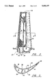
- FIG. 5 is a graphical representation of the temperature gradient of the engine's gas path in proximity to the exterior surface of the airfoil section of the turbine blade.
- the preferred embodiment of this invention is for airfoils of a turbine blade for gas turbine engines.
- the turbine blade generally illustrated by reference numeral 10 is typically cast from metallic material capable of operation in the engines's hostile environment and includes internal air cooling serpentine passageways 12, 14 and 16 separated by elongated ribs 18, 20 and 22. Coolant, typically bled from one of the compressor stages (not shown), is admitted into the serpentine passageways through the inlet 24 disposed at the trailing edge 26 of blade 10.
- the elongated ribs 18, 20 and 22 extend from the inner surface of the wall 30 on the pressure side 32 of the airfoil 10 to the inner surface of the wall 36 on the suction side 38 of airfoil 10.
- the serpentine passageways 12, 14, and 16 extend in the chordwise direction from proximity to the leading edge 40 toward proximity to the trailing edge 42.
- film cooling holes and the shower head holes typically employed in these types of blades are omitted herefrom.
- Heat exchange augmenting devices such as trip strips 44 may be employed to enhance heat transfer for the air flowing through these serpentine passageways.
- FIG. 4 is a sectional view that schematically illustrates this invention.
- the schematic is a blown up sectional view depicting an example of the flow of coolant in the serpentine passageways in heat exchange relationship with the exterior gas path flowing over the pressure and suction surfaces of the turbine airfoil.
- the arrows labeled A represent the gas path and the arrows labeled B represent the coolant flow.
- the arrow B entering the serpentine passageway C flows from the root D to the tip E turns 180 degrees at the end the rib F and flow toward the root D in passageway G, and again turns 180 degrees around rib H at the root of the blade and flows toward the tip E in passageway J.
- the heat exchange function of the cooling serpentine passageways C, G and J which is in indirect heat exchange with the gas path flowing over the exterior of the airfoil, is tailored to match this profile.
- the ribs F and H include a plurality of radially spaced apertures K formed at the extremities thereof in the location where less heat exchange is required. This serves to "short circuit" the flow in the respective passageways, so that less heat transfer is taken place at these areas and heat transfer is high in the region therebetween. Obviously, this short circuiting of the flow paths in the serpentine passageways enhances the heat transfer characteristic of the passageways and the supply pressure required to flow the specific amount of coolant through the blade is reduced with a consequential increase in engine operating performance.
- the blade depicted in this embodiment is likewise treated to match the temperature gradient of the external gas path of the engine.
- Radially spaced apertures 50 are formed adjacent to the upper end of rib 20 and radially spaced apertures 52 are formed adjacent to the lower end of rib 22. This serves to "short circuit" the flow of coolant in the respective serpentine passageway reducing the residence time thereof to match the temperature profile of the gas path that is in indirect heat exchange therewith.
- the invention allows the heat exchanger designer to tailor the performance of the heat exchanger to match the characteristics of the environment in which it operates. Specifically, a heat exchanger operating in an environment with an external temperature profile can be enhanced to provide maximum heat transfer potential at the critical spans.
- the heat exchanger flow system is "short circuited" at areas of low required heat transfer and the heat exchanger potential at areas of high required heat transfer is maximized.
- short circuiting at the walls to allow flow from one passageway to another, reduces the heat transfer in the regions where it is not critical, but keeps the heat transfer high where it is required.
Abstract
Description
Claims (5)
Priority Applications (1)
| Application Number | Priority Date | Filing Date | Title |
|---|---|---|---|
| US08/164,090 US5403157A (en) | 1993-12-08 | 1993-12-08 | Heat exchange means for obtaining temperature gradient balance |
Applications Claiming Priority (1)
| Application Number | Priority Date | Filing Date | Title |
|---|---|---|---|
| US08/164,090 US5403157A (en) | 1993-12-08 | 1993-12-08 | Heat exchange means for obtaining temperature gradient balance |
Publications (1)
| Publication Number | Publication Date |
|---|---|
| US5403157A true US5403157A (en) | 1995-04-04 |
Family
ID=22592931
Family Applications (1)
| Application Number | Title | Priority Date | Filing Date |
|---|---|---|---|
| US08/164,090 Expired - Lifetime US5403157A (en) | 1993-12-08 | 1993-12-08 | Heat exchange means for obtaining temperature gradient balance |
Country Status (1)
| Country | Link |
|---|---|
| US (1) | US5403157A (en) |
Cited By (26)
| Publication number | Priority date | Publication date | Assignee | Title |
|---|---|---|---|---|
| US5498126A (en) * | 1994-04-28 | 1996-03-12 | United Technologies Corporation | Airfoil with dual source cooling |
| US5669759A (en) * | 1995-02-03 | 1997-09-23 | United Technologies Corporation | Turbine airfoil with enhanced cooling |
| US5779447A (en) * | 1997-02-19 | 1998-07-14 | Mitsubishi Heavy Industries, Ltd. | Turbine rotor |
| US5857836A (en) * | 1996-09-10 | 1999-01-12 | Aerodyne Research, Inc. | Evaporatively cooled rotor for a gas turbine engine |
| US5919031A (en) * | 1996-08-23 | 1999-07-06 | Asea Brown Boveri Ag | Coolable blade |
| US5967752A (en) * | 1997-12-31 | 1999-10-19 | General Electric Company | Slant-tier turbine airfoil |
| US5971708A (en) * | 1997-12-31 | 1999-10-26 | General Electric Company | Branch cooled turbine airfoil |
| US6036440A (en) * | 1997-04-01 | 2000-03-14 | Mitsubishi Heavy Industries, Ltd. | Gas turbine cooled moving blade |
| US6186741B1 (en) * | 1999-07-22 | 2001-02-13 | General Electric Company | Airfoil component having internal cooling and method of cooling |
| US6331098B1 (en) | 1999-12-18 | 2001-12-18 | General Electric Company | Coriolis turbulator blade |
| US6471479B2 (en) * | 2001-02-23 | 2002-10-29 | General Electric Company | Turbine airfoil with single aft flowing three pass serpentine cooling circuit |
| US20050031445A1 (en) * | 2003-08-08 | 2005-02-10 | Siemens Westinghouse Power Corporation | Cooling system for a turbine vane |
| US20060013688A1 (en) * | 2004-07-15 | 2006-01-19 | Papple Michael L C | Internally cooled turbine blade |
| US20090097972A1 (en) * | 2007-10-10 | 2009-04-16 | United Technologies Corp. | Gas Turbine Engine Systems and Related Methods Involving Heat Exchange |
| US7641445B1 (en) | 2006-12-01 | 2010-01-05 | Florida Turbine Technologies, Inc. | Large tapered rotor blade with near wall cooling |
| US7645122B1 (en) * | 2006-12-01 | 2010-01-12 | Florida Turbine Technologies, Inc. | Turbine rotor blade with a nested parallel serpentine flow cooling circuit |
| US7955053B1 (en) | 2007-09-21 | 2011-06-07 | Florida Turbine Technologies, Inc. | Turbine blade with serpentine cooling circuit |
| US8864467B1 (en) * | 2012-01-26 | 2014-10-21 | Florida Turbine Technologies, Inc. | Turbine blade with serpentine flow cooling |
| DE10316909B4 (en) * | 2002-05-16 | 2016-01-07 | Alstom Technology Ltd. | Coolable turbine blade with ribs in the cooling channel |
| US9518468B2 (en) | 2011-02-17 | 2016-12-13 | Rolls-Royce Plc | Cooled component for the turbine of a gas turbine engine |
| US20170226869A1 (en) * | 2016-02-08 | 2017-08-10 | General Electric Company | Turbine engine airfoil with cooling |
| US20180283183A1 (en) * | 2017-04-03 | 2018-10-04 | General Electric Company | Turbine engine component with a core tie hole |
| US10378364B2 (en) * | 2017-11-07 | 2019-08-13 | United Technologies Corporation | Modified structural truss for airfoils |
| US10612394B2 (en) * | 2017-07-21 | 2020-04-07 | United Technologies Corporation | Airfoil having serpentine core resupply flow control |
| US10871074B2 (en) | 2019-02-28 | 2020-12-22 | Raytheon Technologies Corporation | Blade/vane cooling passages |
| US11149550B2 (en) | 2019-02-07 | 2021-10-19 | Raytheon Technologies Corporation | Blade neck transition |
Citations (7)
| Publication number | Priority date | Publication date | Assignee | Title |
|---|---|---|---|---|
| CA741680A (en) * | 1966-08-30 | Raskin Walter | Heat exchange panel and method of making same | |
| JPS611804A (en) * | 1984-06-12 | 1986-01-07 | Ishikawajima Harima Heavy Ind Co Ltd | Cooling-type turbine wing |
| US4574876A (en) * | 1981-05-11 | 1986-03-11 | Extracorporeal Medical Specialties, Inc. | Container with tapered walls for heating or cooling fluids |
| US4587700A (en) * | 1984-06-08 | 1986-05-13 | The Garrett Corporation | Method for manufacturing a dual alloy cooled turbine wheel |
| SU1291093A1 (en) * | 1984-03-28 | 1987-02-23 | Головное Специализированное Конструкторское Бюро По Комплексу Машин Для Ферм Крупного Рогатого Скота | Apparatus for thermal treatment of milk |
| US4775296A (en) * | 1981-12-28 | 1988-10-04 | United Technologies Corporation | Coolable airfoil for a rotary machine |
| US4992026A (en) * | 1986-03-31 | 1991-02-12 | Kabushiki Kaisha Toshiba | Gas turbine blade |
-
1993
- 1993-12-08 US US08/164,090 patent/US5403157A/en not_active Expired - Lifetime
Patent Citations (7)
| Publication number | Priority date | Publication date | Assignee | Title |
|---|---|---|---|---|
| CA741680A (en) * | 1966-08-30 | Raskin Walter | Heat exchange panel and method of making same | |
| US4574876A (en) * | 1981-05-11 | 1986-03-11 | Extracorporeal Medical Specialties, Inc. | Container with tapered walls for heating or cooling fluids |
| US4775296A (en) * | 1981-12-28 | 1988-10-04 | United Technologies Corporation | Coolable airfoil for a rotary machine |
| SU1291093A1 (en) * | 1984-03-28 | 1987-02-23 | Головное Специализированное Конструкторское Бюро По Комплексу Машин Для Ферм Крупного Рогатого Скота | Apparatus for thermal treatment of milk |
| US4587700A (en) * | 1984-06-08 | 1986-05-13 | The Garrett Corporation | Method for manufacturing a dual alloy cooled turbine wheel |
| JPS611804A (en) * | 1984-06-12 | 1986-01-07 | Ishikawajima Harima Heavy Ind Co Ltd | Cooling-type turbine wing |
| US4992026A (en) * | 1986-03-31 | 1991-02-12 | Kabushiki Kaisha Toshiba | Gas turbine blade |
Cited By (33)
| Publication number | Priority date | Publication date | Assignee | Title |
|---|---|---|---|---|
| US5498126A (en) * | 1994-04-28 | 1996-03-12 | United Technologies Corporation | Airfoil with dual source cooling |
| US5669759A (en) * | 1995-02-03 | 1997-09-23 | United Technologies Corporation | Turbine airfoil with enhanced cooling |
| CN1105227C (en) * | 1996-08-23 | 2003-04-09 | 阿尔斯通公司 | Coolable blade |
| US5919031A (en) * | 1996-08-23 | 1999-07-06 | Asea Brown Boveri Ag | Coolable blade |
| US5857836A (en) * | 1996-09-10 | 1999-01-12 | Aerodyne Research, Inc. | Evaporatively cooled rotor for a gas turbine engine |
| US5779447A (en) * | 1997-02-19 | 1998-07-14 | Mitsubishi Heavy Industries, Ltd. | Turbine rotor |
| DE19814680C2 (en) * | 1997-04-01 | 2001-10-25 | Mitsubishi Heavy Ind Ltd | Cooled gas turbine blade |
| US6036440A (en) * | 1997-04-01 | 2000-03-14 | Mitsubishi Heavy Industries, Ltd. | Gas turbine cooled moving blade |
| US5971708A (en) * | 1997-12-31 | 1999-10-26 | General Electric Company | Branch cooled turbine airfoil |
| US5967752A (en) * | 1997-12-31 | 1999-10-19 | General Electric Company | Slant-tier turbine airfoil |
| US6186741B1 (en) * | 1999-07-22 | 2001-02-13 | General Electric Company | Airfoil component having internal cooling and method of cooling |
| US6331098B1 (en) | 1999-12-18 | 2001-12-18 | General Electric Company | Coriolis turbulator blade |
| US6471479B2 (en) * | 2001-02-23 | 2002-10-29 | General Electric Company | Turbine airfoil with single aft flowing three pass serpentine cooling circuit |
| DE10316909B4 (en) * | 2002-05-16 | 2016-01-07 | Alstom Technology Ltd. | Coolable turbine blade with ribs in the cooling channel |
| US20050031445A1 (en) * | 2003-08-08 | 2005-02-10 | Siemens Westinghouse Power Corporation | Cooling system for a turbine vane |
| US6955523B2 (en) * | 2003-08-08 | 2005-10-18 | Siemens Westinghouse Power Corporation | Cooling system for a turbine vane |
| US7198468B2 (en) * | 2004-07-15 | 2007-04-03 | Pratt & Whitney Canada Corp. | Internally cooled turbine blade |
| US20060013688A1 (en) * | 2004-07-15 | 2006-01-19 | Papple Michael L C | Internally cooled turbine blade |
| US7641445B1 (en) | 2006-12-01 | 2010-01-05 | Florida Turbine Technologies, Inc. | Large tapered rotor blade with near wall cooling |
| US7645122B1 (en) * | 2006-12-01 | 2010-01-12 | Florida Turbine Technologies, Inc. | Turbine rotor blade with a nested parallel serpentine flow cooling circuit |
| US7955053B1 (en) | 2007-09-21 | 2011-06-07 | Florida Turbine Technologies, Inc. | Turbine blade with serpentine cooling circuit |
| US20090097972A1 (en) * | 2007-10-10 | 2009-04-16 | United Technologies Corp. | Gas Turbine Engine Systems and Related Methods Involving Heat Exchange |
| US7946806B2 (en) | 2007-10-10 | 2011-05-24 | United Technologies Corporation | Gas turbine engine systems and related methods involving heat exchange |
| US9518468B2 (en) | 2011-02-17 | 2016-12-13 | Rolls-Royce Plc | Cooled component for the turbine of a gas turbine engine |
| US8864467B1 (en) * | 2012-01-26 | 2014-10-21 | Florida Turbine Technologies, Inc. | Turbine blade with serpentine flow cooling |
| US20170226869A1 (en) * | 2016-02-08 | 2017-08-10 | General Electric Company | Turbine engine airfoil with cooling |
| US10808547B2 (en) * | 2016-02-08 | 2020-10-20 | General Electric Company | Turbine engine airfoil with cooling |
| US20180283183A1 (en) * | 2017-04-03 | 2018-10-04 | General Electric Company | Turbine engine component with a core tie hole |
| US11021967B2 (en) * | 2017-04-03 | 2021-06-01 | General Electric Company | Turbine engine component with a core tie hole |
| US10612394B2 (en) * | 2017-07-21 | 2020-04-07 | United Technologies Corporation | Airfoil having serpentine core resupply flow control |
| US10378364B2 (en) * | 2017-11-07 | 2019-08-13 | United Technologies Corporation | Modified structural truss for airfoils |
| US11149550B2 (en) | 2019-02-07 | 2021-10-19 | Raytheon Technologies Corporation | Blade neck transition |
| US10871074B2 (en) | 2019-02-28 | 2020-12-22 | Raytheon Technologies Corporation | Blade/vane cooling passages |
Similar Documents
| Publication | Publication Date | Title |
|---|---|---|
| US5403157A (en) | Heat exchange means for obtaining temperature gradient balance | |
| US5486093A (en) | Leading edge cooling of turbine airfoils | |
| US6164914A (en) | Cool tip blade | |
| US5857837A (en) | Coolable air foil for a gas turbine engine | |
| US5156526A (en) | Rotation enhanced rotor blade cooling using a single row of coolant passageways | |
| US5813836A (en) | Turbine blade | |
| US6471479B2 (en) | Turbine airfoil with single aft flowing three pass serpentine cooling circuit | |
| US9447692B1 (en) | Turbine rotor blade with tip cooling | |
| US6991430B2 (en) | Turbine blade with recessed squealer tip and shelf | |
| US5997251A (en) | Ribbed turbine blade tip | |
| US5975850A (en) | Turbulated cooling passages for turbine blades | |
| US7632062B2 (en) | Turbine rotor blades | |
| US8047787B1 (en) | Turbine blade with trailing edge root slot | |
| US5733102A (en) | Slot cooled blade tip | |
| US5403159A (en) | Coolable airfoil structure | |
| EP1726785B1 (en) | Turbine airfoil platform cooling circuit | |
| US8240981B2 (en) | Turbine airfoil with platform cooling | |
| US5797726A (en) | Turbulator configuration for cooling passages or rotor blade in a gas turbine engine | |
| EP1001137B1 (en) | Gas turbine airfoil with axial serpentine cooling circuits | |
| EP1600604B1 (en) | Cooler rotor blade and method for cooling a rotor blade | |
| US3220697A (en) | Hollow turbine or compressor vane | |
| US6273682B1 (en) | Turbine blade with preferentially-cooled trailing edge pressure wall | |
| US4786234A (en) | Turbine airfoil | |
| US8454301B1 (en) | Turbine blade with serpentine cooling | |
| GB2184492A (en) | Film cooled vanes for turbines |
Legal Events
| Date | Code | Title | Description |
|---|---|---|---|
| AS | Assignment |
Owner name: UNITED TECHNOLOGIES CORPORATION, CONNECTICUT Free format text: ASSIGNMENT OF ASSIGNORS INTEREST;ASSIGNOR:MOORE, ROBERT P.;REEL/FRAME:006813/0016 Effective date: 19931206 |
|
| STCF | Information on status: patent grant |
Free format text: PATENTED CASE |
|
| CC | Certificate of correction | ||
| AS | Assignment |
Owner name: NAVY, SECRETARY OF THE, UNITED STATES OF AMERICA, Free format text: CONFIRMATORY LICENSE;ASSIGNOR:UNITED TECHNOLOGIES CORPORATION;REEL/FRAME:008477/0751 Effective date: 19940203 |
|
| FEPP | Fee payment procedure |
Free format text: PAYOR NUMBER ASSIGNED (ORIGINAL EVENT CODE: ASPN); ENTITY STATUS OF PATENT OWNER: LARGE ENTITY |
|
| FPAY | Fee payment |
Year of fee payment: 4 |
|
| FPAY | Fee payment |
Year of fee payment: 8 |
|
| FEPP | Fee payment procedure |
Free format text: PAYOR NUMBER ASSIGNED (ORIGINAL EVENT CODE: ASPN); ENTITY STATUS OF PATENT OWNER: LARGE ENTITY Free format text: PAYER NUMBER DE-ASSIGNED (ORIGINAL EVENT CODE: RMPN); ENTITY STATUS OF PATENT OWNER: LARGE ENTITY |
|
| FPAY | Fee payment |
Year of fee payment: 12 |