JP4732003B2 - Driving force control device for electric vehicle - Google Patents
Driving force control device for electric vehicle Download PDFInfo
- Publication number
- JP4732003B2 JP4732003B2 JP2005156087A JP2005156087A JP4732003B2 JP 4732003 B2 JP4732003 B2 JP 4732003B2 JP 2005156087 A JP2005156087 A JP 2005156087A JP 2005156087 A JP2005156087 A JP 2005156087A JP 4732003 B2 JP4732003 B2 JP 4732003B2
- Authority
- JP
- Japan
- Prior art keywords
- wheel
- pressure
- brake
- motor
- control
- Prior art date
- Legal status (The legal status is an assumption and is not a legal conclusion. Google has not performed a legal analysis and makes no representation as to the accuracy of the status listed.)
- Expired - Fee Related
Links
Images

Landscapes
- Electric Propulsion And Braking For Vehicles (AREA)
- Regulating Braking Force (AREA)
Description
本発明は、少なくともモータの駆動力を車輪に伝達する電動車両の駆動力制御装置に関する。 The present invention relates to a driving force control device for an electric vehicle that transmits at least driving force of a motor to wheels.
近年、自動車等の車両においては、ガソリン等を燃料とするエンジンを動力源として搭載する車両に対し、低公害、省資源の促進を目的として、バッテリからの電力によって駆動力を発生するモータを搭載する電気自動車や、エンジンに加えてモータを搭載し、エンジンとモータとを併用するハイブリッド車等の電動車両が実用化の段階となっている。 In recent years, vehicles such as automobiles are equipped with a motor that generates driving force by the power from the battery, in order to promote low-pollution and resource-saving, for vehicles equipped with an engine powered by gasoline or the like as a power source. Electric vehicles, and electric vehicles such as hybrid vehicles that are equipped with a motor in addition to an engine and use both the engine and the motor are in the stage of practical use.
この種の電動車両では、モータによる回生制動が可能であることから、ブレーキペダルの踏力に応じたブレーキ圧を電子的に制御する電子制御ブレーキシステム(EBS)を採用することが多い。しかしながら、この電子制御ブレーキシステムにアンチロックブレーキシステム(ABS)を併用した場合、モータによる回生制動とABS制御との切換えを円滑に行う必要がある。 Since this type of electric vehicle is capable of regenerative braking by a motor, an electronically controlled brake system (EBS) that electronically controls the brake pressure in accordance with the depression force of the brake pedal is often employed. However, when an anti-lock brake system (ABS) is used in combination with this electronically controlled brake system, it is necessary to smoothly switch between regenerative braking by the motor and ABS control.
このため、特許文献1には、ABS制御開始後の減圧を検知した場合、回生制動トルクをゼロ化して回生協調ブレーキ制御を終了することにより、回生制動モードからABSモードへの切換え時にブレーキペダルのショックを軽減させると共に、減圧不要の通常ブレーキ時に回生制動モードの機会を確保する技術が開示されている。
しかしながら、ABSを作動させてブレーキ圧を減圧したとき、回生制動を中止するのみでは、車速や路面条件等の影響を受けてロック状態にある車輪の回転復帰が遅くなる虞があり、ABSによるアンチスリップ制御性の効果を必ずしも十分に得られない場合がある。 However, when the brake pressure is reduced by operating the ABS, if the regenerative braking is only stopped, there is a possibility that the wheel rotation recovery in the locked state may be delayed due to the influence of the vehicle speed, the road surface condition, etc. The effect of slip controllability may not always be obtained sufficiently.
本発明は上記事情に鑑みてなされたもので、ロック状態にある車輪の回転を早期に復帰させ、十分なブレーキ性能を確保しつつアンチロックブレーキ制御の応答性とアンチロックブレーキ作動時の方向安定性とを向上することのできる電動車両の駆動力制御装置を提供することを目的としている。 The present invention has been made in view of the above circumstances, and the rotation of the wheel in the locked state is quickly restored, and the response of the antilock brake control and the direction stability during the operation of the antilock brake are ensured while ensuring sufficient brake performance. It is an object of the present invention to provide a driving force control device for an electric vehicle that can improve performance.
上記目的を達成するため、本発明による電動車両の駆動力制御装置は、少なくともモータの駆動力を車輪に伝達し、ブレーキ系の圧力を電子的に制御する電子制御ブレーキシステムと、制動による上記車輪のロック状態を判定して上記車輪のブレーキ圧力を調整するアンチロックブレーキシステムとを備えた電動車両の駆動力制御装置であって、上記車輪がロック状態と判定したときの車体速度を車輪速度に基いて推定し、推定した車体速度に相当する目標車輪速度に上記モータから車軸までの減速比を乗算して上記モータの目標回転数を設定する手段と、上記アンチロックブレーキシステムが作動して上記車輪のブレーキ圧力を減圧する減圧モードにあるとき、上記モータによる回生制動を中止し、ロック状態にある上記車輪の回転慣性に上記目標車輪速度と実車輪速度との偏差を乗算して求めた駆動トルクを上記モータに発生させてロック状態にある上記車輪の車輪速度をアップさせる手段とを備えたことを特徴とする。
In order to achieve the above object, a driving force control apparatus for an electric vehicle according to the present invention includes an electronically controlled brake system that transmits at least a driving force of a motor to a wheel and electronically controls a pressure of a brake system, and the wheel by braking. An anti-lock brake system for determining the lock state of the wheel and adjusting the brake pressure of the wheel, wherein the vehicle body speed when the wheel is determined to be locked is changed to the wheel speed. Means for setting the target rotational speed of the motor by multiplying the target wheel speed corresponding to the estimated vehicle body speed by the reduction ratio from the motor to the axle, and the antilock brake system is operated to when in the braking pressure of the wheel in a vacuum mode in which vacuum stops regenerative braking by the motor, the rotational inertia of the wheel in the locked state The serial target wheel speed and the driving torque obtained by multiplying the difference between the actual wheel speed, characterized in that a means for up wheel speed of the wheel in the locked state is generated in the motor.
本発明による電動車両の駆動力制御装置は、ロック状態にある車輪の回転を早期に復帰させることができ、十分なブレーキ性能を確保しつつアンチロックブレーキ制御の応答性とアンチロックブレーキ作動時の方向安定性とを向上することができる。 The driving force control device for an electric vehicle according to the present invention can restore the rotation of the wheel in the locked state at an early stage, while ensuring sufficient braking performance and the response of the anti-lock brake control and the anti-lock brake operation. Directional stability can be improved.
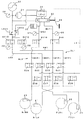
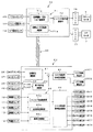
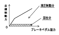
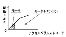
以下、図面を参照して本発明の実施の形態を説明する。図1〜図6は本発明の実施の一形態に係わり、図1はハイブリッド車のシステム構成図、図2は電子制御ブレーキのシステム系統図、図3はHEVモータ制御系とブレーキ制御系のブロック図、図4は制動力マップの特性例を示す説明図、図5は駆動トルクマップの特性例を示す説明図、図6は車輪速復帰制御ルーチンのフローチャートである。 Embodiments of the present invention will be described below with reference to the drawings. 1 to 6 relate to an embodiment of the present invention, FIG. 1 is a system configuration diagram of a hybrid vehicle, FIG. 2 is a system diagram of an electronically controlled brake, and FIG. 3 is a block diagram of an HEV motor control system and a brake control system. FIG. 4 is an explanatory diagram showing an example of characteristics of a braking force map, FIG. 5 is an explanatory diagram showing an example of characteristics of a driving torque map, and FIG. 6 is a flowchart of a wheel speed return control routine.
本発明は、バッテリからの電力によって走行駆動力を発生するモータを搭載する電気自動車や、ガソリン等を燃料とするエンジンとモータとを搭載し、エンジンとモータとの少なくとも一方で走行駆動力を発生するハイブリッド車等の電動車両に適用されるものであり、図1においては、電動車両としてのハイブリッド車1に本発明を適用した例を示している。
The present invention includes an electric vehicle equipped with a motor that generates a driving force by power from a battery, an engine and a motor that use gasoline as fuel, and generates the driving force of at least one of the engine and the motor. FIG. 1 illustrates an example in which the present invention is applied to a
本形態のハイブリッド車1は、駆動系として、車両前部のエンジン2に変速機4を介して連結されるフロントモータ5と、リヤの減速差動機構6に連結されるリヤモータ7との2つのモータを搭載しており、エンジン2とフロントモータ5との少なくとも一方の駆動力を変速機4からフロント車軸8を介して左右の前輪FtLH,FtLHに伝達すると共に、リヤモータ7の駆動力を減速差動機構6からリヤ車軸9を介して左右の後輪RrLH,RrRHに駆動力を伝達する4輪駆動車である。尚、エンジン2と変速機4との間には、エンジン2の駆動力を断続するクラッチ3が介装されている。
The
また、ハイブリッド車1には、電子制御系として、エンジン2及び変速機4を制御するエンジン・変速コントローラ(EG&TM_ECU)50、後述する電子制御ブレーキシステム(EBS)を制御するブレーキコントローラ(BRK_ECU)60、フロントモータ5及びリヤモータ7を制御すると共にシステム全体を統括する中央のハイブリッドコントローラ(HEV_ECU)70が備えられている。各コントローラは、マイクロコンピュータを中心として各種インターフェースや周辺回路を備えて構成され、CAN(Controller Area Network)等の通信バス80を介して双方向通信可能に接続され、制御情報や制御対象の動作状態に係わるセンシング情報が相互交換される。
Further, the
エンジン・変速コントローラ50は、中央のハイブリッドコントローラ70からの制御指令を受け、エンジン2及び変速機4を制御する。エンジン制御としては、エンジン2の運転状態を検出する各種センサ・スイッチ類からの信号に基づいて、スロットル開度、点火時期、燃料噴射量等のパラメータを演算し、これらのパラメータの制御信号によってアクチュエータ類を駆動し、エンジン2の駆動力が制御指令値に一致するよう、エンジン2の運転状態を制御する。また、変速機制御としては、変速機4の油圧を制御し、運転状態に応じて決定した変速段、例えばアクセル開度(アクセルペダルストローク)と車速とに基づく変速線図に基づいて決定した変速段への切換制御を行う。
The engine /
ブレーキコントローラ60は、ブレーキペダルの踏力に応じて、ハイブリッドコントローラ70によるモータの回生制動との協調制御下で電子制御ブレーキシステムによるブレーキ制御を行う。このブレーキ制御においては、左右の前輪FtLH,FtRHの回転(車輪速度)を検出する車輪速センサ10,11、左右の後輪RrLH,RrRHの回転を検出する車輪速センサ12,13からの信号に基づいて車輪のスリップを監視し、車輪のスリップ率が規定の判定値を越えた場合、車輪がロック状態にあると判定してアンチロックブレーキシステム(ABS)に対する制御を実行する。以下では、車輪のスリップ率が規定の判定値を越えた場合を、単に「車輪がロックした」と表現する。
The
ハイブリッドコントローラ70は、フロントモータ5の回転を検出するフロント回転センサ14、リヤモータ7の回転を検出するリヤ回転センサ15、その他、運転者の運転操作を含む運転状態を検出する図示しない各種センサ・スイッチ類からの信号を入力し、運転者の要求に応じた車両の要求駆動トルクを演算する。そして、この要求駆動トルクをエンジン2,フロントモータ5,リヤモータ7に適宜分配し、エンジン・変速コントローラ50に制御指令を出力すると共に、フロントモータ5,リヤモータ7を、それぞれインバータ16,17を介して駆動制御する。
The
また、ハイブリッドコントローラ70は、ブレーキコントローラ60からの制御情報に基づいて制動開始と認識したとき、クラッチ3を開放してエンジン2の出力を切離し、フロントモータ5及びリヤモータ7の回生制動によるモータのみの走行に切換える。このモータのみの走行においては、ブレーキによる車輪ロックが発生したとき、ロックした車輪に対する回生制動が中止され、ABSによるブレーキ圧の減圧タイミングに合わせて比較的大きな駆動トルクTMMを発生させることにより、ロックした車輪の回転を早期に復帰させる車輪速復帰制御を実行する。
When the
すなわち、従来、ブレーキにより車輪がロックしたときには、ABSを作動させてブレーキ圧を減圧しているが、このブレーキ圧の減圧や回生の中止のみでは、ロックした車輪の回転復帰が車速や路面条件等の影響を受け、必ずしも十分な効果を得られない場合がある。従って、ハイブリッドコントローラ70は、ロックした車輪に対して受動的にブレーキ圧を減圧するのみではなく、回生中止及びブレーキ圧の減圧下でロックした車輪に積極的に駆動トルクTMMを与えることにより、回転復帰を促進する。
In other words, conventionally, when the wheel is locked by the brake, the ABS is operated to reduce the brake pressure. However, only by reducing the brake pressure or stopping the regeneration, the rotation of the locked wheel can be returned to the vehicle speed, road surface condition, etc. In some cases, a sufficient effect cannot always be obtained. Therefore, the
また、このとき、回転復帰の効果を上げるため、ABSによるブレーキ減圧後の加圧時に、駆動系のガタ等による機械的な応答遅れを抑制するため、微小駆動トルクTMminを与えるようにしており、更に、この微小駆動トルクTMmin発生時には、ブレーキ制御圧を微小駆動トルクTMmin分だけ高め、万一、運転者がスリップを察知してブレーキペダルの踏み込みを緩めた場合にも、ABSによる加圧時の制動力を確保する。 At this time, in order to increase the effect of rotation recovery, a minute driving torque TMmin is applied in order to suppress mechanical response delay due to backlash of the driving system at the time of pressurization after the brake pressure reduction by ABS, Furthermore, when this minute driving torque TMmin occurs, the brake control pressure is increased by the minute driving torque TMmin, and even if the driver senses slip and depresses the brake pedal, Ensure braking force.
ここで、ABSを併設した本形態の電子制御ブレーキシステム(EBS)について説明する。本形態の電子制御ブレーキシステムは、図2に示すように、左前輪FtLH及び左後輪RrLHに対応するブレーキラインBL1と、右前輪FtRH及び右後輪RrRHに対応するブレーキラインBL2との独立した2系統の油圧ラインを備えている。 Here, an electronically controlled brake system (EBS) of this embodiment with an ABS will be described. As shown in FIG. 2, the electronically controlled brake system of the present embodiment is independent of the brake line BL1 corresponding to the left front wheel FtLH and the left rear wheel RrLH and the brake line BL2 corresponding to the right front wheel FtRH and the right rear wheel RrRH. Two hydraulic lines are provided.
ブレーキラインBL1は、左前輪FtLHのホイールシリンダ20に接続されるホイールシリンダラインW1Ftと、左後輪RrLHのホイールシリンダ21に接続されるホイールシリンダラインW1Rrとが合流され、更に、合流点の上流側が、タンデムマスタシリンダ一体型のハイドロブースタ30の一方のシリンダからの液圧を導くマスタシリンダラインMC1と、電動ポンプ31及びアキュムレータ32によって形成される圧力源から制御圧を導く一方の制御圧ラインEB1とに分岐されて形成されている。
In the brake line BL1, the wheel cylinder line W1Ft connected to the
また、ブレーキラインBL2は、右前輪FtRHのホイールシリンダ22に接続されるホイールシリンダラインW2Ftと、右後輪RrRHのホイールシリンダ23に接続されるホイールシリンダラインW2Rrとが合流され、更に、合流点の上流側が、ハイドロブースタ30の他方のシリンダからの液圧を導くマスタシリンダラインMC2と、電動ポンプ31及びアキュムレータ32によって形成される圧力源から制御圧を導く他方の制御圧ラインEB2とに分岐されて形成されている。
The brake line BL2 is a combination of a wheel cylinder line W2Ft connected to the wheel cylinder 22 of the right front wheel FtRH and a wheel cylinder line W2Rr connected to the
各ホイールシリンダラインW1Ft,W1Rr,W2Ft,W2Rrには、それぞれ、各ホイールシリンダにブレーキ圧を加圧するためのABS加圧弁SV1,SV2,SV3,SV4が介装されている。また、各ホイールシリンダラインW1Ft,W1Rr,W2Ft,W2Rrは、各ABS加圧弁SV1〜SV4と各ホイールシリンダ20〜23との間で分岐され、それぞれ、ブレーキ圧を減圧するためのABS減圧弁SV5,SV6,SV7,SV8を介して減圧ラインL3に合流され、ハイドロブースタ30及びアキュムレータ32に供給するブレーキ液を貯留するリザーバ33に接続されている。
Each wheel cylinder line W1Ft, W1Rr, W2Ft, W2Rr is provided with ABS pressurization valves SV1, SV2, SV3, SV4 for pressurizing the brake pressure to the respective wheel cylinders. The wheel cylinder lines W1Ft, W1Rr, W2Ft, and W2Rr are branched between the ABS pressurizing valves SV1 to SV4 and the
ハイドロブースタ30は、ブレーキペダル34の踏力を増幅するブースタ部(B)と2つのマスタシリンダ部とアキュムレータ32からの液圧を調圧してブースタ部(B)にフィードバックするレギュレータ部(R)とを同軸上に配置して構成されている。ハイドロブースタ30の一方のマスタシリンダ部は、マスタシリンダラインMC1に介装される切換弁SV9を介してホイールシリンダラインW1Ft,W1Rrの合流部に接続され、他方のマスタシリンダ部は、マスタシリンダラインMC2に介装されるストロークシミュレータ35及び切換弁SV10を介してホイールシリンダラインW2Ft,W2Rrの合流部に接続されている。
The
また、マスタシリンダラインMC1,MC2には、マスタシリンダ部からの液圧を検出する圧力センサ(MC圧センサ)36,37が切換弁SV9,SV10の上流側に取付けられている。これらのMC圧センサ36,37によって検出される圧力は、運転者のブレーキ操作によるブレーキペダル34のペダル踏力として用いられ、ペダル踏力に応じたブレーキ圧が決定される。
In addition, pressure sensors (MC pressure sensors) 36 and 37 for detecting the hydraulic pressure from the master cylinder portion are attached to the upstream sides of the switching valves SV9 and SV10 in the master cylinder lines MC1 and MC2. The pressures detected by these
尚、ストロークシミュレータ35は、シリンダと圧縮ばねとで構成され、EBS作動時、ブレーキ圧に応じてシリンダに形成された圧力室の体積を増減させ、ブレーキペダル34のストロークに対し、自然なフィーリングを得るためのものである。
The
一方、アキュムレータ32には、リザーバ33に貯留されているブレーキ液が電動ポンプ31によって圧送される。このアキュムレータ32に蓄圧された圧力は、圧力センサ38により検出され、検出圧力が設定値以下になると、電動ポンプ31が駆動されてアキュムレータ32の圧力が設定圧力に達するまで加圧される。
On the other hand, the brake fluid stored in the reservoir 33 is pumped to the accumulator 32 by the electric pump 31. The pressure accumulated in the accumulator 32 is detected by the
アキュムレータ32の下流側は、ハイドロブースタ30のレギュレータ部(R)に接続されると共に、リニア制御加圧弁LSV1に接続されている。このリニア制御加圧弁LSV1の下流側は、リニア制御減圧弁LSV2を介してリザーバ33に接続されると共に、各制御圧ラインEB1,EB2に、それぞれ、切換弁SV12,SV13を介して接続されている。
The downstream side of the accumulator 32 is connected to the regulator section (R) of the
リニア制御加圧弁LSV1,リニア制御減圧弁LSV2は、通路開口をリニアに変化させる制御弁であり、各制御圧ラインEB1,EB2の切換弁SV12,SV13の直下流に取付けられた圧力センサ(WC圧センサ)39,40の信号に基づいて制御される。すなわち、アキュムレータ32に蓄圧された高圧の液圧をリニア制御加圧弁LSV1及びリニア制御減圧弁LSV2で調圧し、WC圧センサ39,40で検出した各ホイールシリンダ20〜23の実ホイールシリンダ圧が目標値に一致するように制御する。 The linear control pressure increasing valve LSV1 and the linear control pressure reducing valve LSV2 are control valves that linearly change the passage opening, and are pressure sensors (WC pressure) mounted immediately downstream of the switching valves SV12 and SV13 of the control pressure lines EB1 and EB2. It is controlled based on signals from sensors 39 and 40. That is, the high hydraulic pressure accumulated in the accumulator 32 is regulated by the linear control pressure increasing valve LSV1 and the linear control pressure reducing valve LSV2, and the actual wheel cylinder pressure of each wheel cylinder 20-23 detected by the WC pressure sensors 39, 40 is the target. Control to match the value.
本形態においては、システムに異常が生じていない正常時、マスタシリンダラインMC1,MC2の切換弁SV9,SV10は閉弁状態とされ、制御圧ラインEB1,EB2の切換弁SV12,13が開弁状態とされる。このため、ブレーキペダル34が踏み込まれことによりマスタシリンダ圧が上昇すると、マスタシリンダ内のブレーキ液はストロークシミュレータ35へ流入する一方、ブレーキペダル34の踏み込みが解除され、マスタシリンダ圧が低下すると、ストロークシミュレータ35内のブレーキ液はマスタシリンダへ流入する。従って、切換弁SV9,SV10が閉弁されている状況下において、ストロークシミュレータ35内の圧縮ばね特性によりブレーキペダル34に対してペダル踏力に応じたストロークを発生させることができる。
In this embodiment, when there is no abnormality in the system, the switching valves SV9 and SV10 of the master cylinder lines MC1 and MC2 are closed and the switching valves SV12 and SV13 of the control pressure lines EB1 and EB2 are opened. It is said. For this reason, when the master cylinder pressure increases due to the depression of the
システム異常が検出された場合には、切換弁SV12,SV13が閉弁され、切換弁SV9,SV10が開弁される。従って、マスタシリンダラインMC1がホイールシリンダラインW1Ft,W1Rrに連通されると共に、マスタシリンダラインMC2がホイールシリンダラインW2Ft,W2Rrに連通され、各ホイールシリンダ20〜23のホイールシリンダ圧をマスタシリンダ圧まで昇圧することが可能となり、安全が確保される。 When a system abnormality is detected, the switching valves SV12 and SV13 are closed and the switching valves SV9 and SV10 are opened. Therefore, the master cylinder line MC1 is communicated with the wheel cylinder lines W1Ft and W1Rr, and the master cylinder line MC2 is communicated with the wheel cylinder lines W2Ft and W2Rr to increase the wheel cylinder pressure of each wheel cylinder 20-23 to the master cylinder pressure. Safety is ensured.
尚、切換弁SV9,SV10の上流側の圧力と下流側の圧力、すなわち、マスタシリンダ側の圧力と各制御圧ラインEB1,EB2の圧力とは、常時ほぼ同じ圧力に維持されており、システム異常発生時にも確実且つ迅速なブレーキ操作が可能なようにバックアップしている。 The upstream side pressure and downstream side pressure of the switching valves SV9 and SV10, that is, the pressure on the master cylinder side and the pressures on the control pressure lines EB1 and EB2 are always maintained at substantially the same pressure, resulting in a system malfunction. Backs up so that reliable and quick brake operation is possible even when it occurs.
次に、ブレーキコントローラ60及びハイブリッドコントローラ70によるブレーキ制御に係わる機能について、図3のブロック図を用いて説明する。
Next, functions related to brake control by the
ブレーキコントローラ60は、EBS制御機能として、目標液圧演算部61、ローパスフィルタ62、実平均液圧演算部63、リニア制御弁指令値演算部64を備え、ABS制御機能として、ABS制御部65、ABS制御弁指令値演算部66を備えている。ABS制御部65は、スリップ検知演算部65a、推定車速演算部65b、減速度演算部65cを備えている。
The
目標液圧演算部61は、運転者がブレーキペダル34を踏み込んだときのペダル踏力を、MC圧センサ36,37によってマスタシリンダラインMC1,MC2の圧力として検出し、このペダル踏力に対応した要求制動力と、通信バス80を介してハイブリッドコントローラ70から送信されたモータ回生情報及び後述する液圧アップ指令に基づく制動力とに基づいて目標制動力を決定する。そして、この目標制動力に対応して、各ホイールシリンダ20〜23に印加するホイールシリンダ圧の目標値(目標液圧)を算出する。
The target hydraulic pressure calculation unit 61 detects the pedal depression force when the driver depresses the
ペダル踏力に対応した制動力は、例えば、図4に例示するマップを参照して決定することができる。図4の例では、ペダル踏力に対して前半で制動力を大きい勾配で直線的に増加させ、急ブレーキ時にも確実に対応できるようにしている。 The braking force corresponding to the pedal effort can be determined with reference to, for example, a map illustrated in FIG. In the example of FIG. 4, the braking force is increased linearly with a large gradient in the first half with respect to the pedal depression force, so that it is possible to reliably cope with sudden braking.
ローパスフィルタ62は、WC圧センサ39,40の信号に含まれる脈動成分やノイズ成分を除去するものであり、実平均液圧演算部63は、このローパスフィルタを通過した信号を処理し、各ホイールシリンダ20〜23回路内ブレーキ液の実平均液圧を算出する。
The low-pass filter 62 removes pulsation components and noise components included in the signals of the WC pressure sensors 39 and 40, and the actual average hydraulic pressure calculation unit 63 processes the signal that has passed through the low-pass filter, and each wheel The actual average hydraulic pressure of the brake fluid in the
リニア制御弁指令値演算部64は、目標液圧演算部61で算出した目標液圧と実平均液圧演算部63で検出した実平均液圧との偏差errに基づいて、アキュムレータ32に蓄圧された圧力を調圧するリニア制御加圧弁LSV1及びリニア制御減圧弁LSV2に対する制御指令値を演算する。この制御指令値に基づいてリニア制御加圧弁LSV1及びリニア制御減圧弁LSV2の開度が可変され、各ホイールシリンダ20〜23の実平均液圧が目標液圧に収束するようフィードバック制御される。 The linear control valve command value calculation unit 64 is accumulated in the accumulator 32 based on the deviation err between the target hydraulic pressure calculated by the target hydraulic pressure calculation unit 61 and the actual average hydraulic pressure detected by the actual average hydraulic pressure calculation unit 63. The control command value for the linear control pressure increasing valve LSV1 and the linear control pressure reducing valve LSV2 for adjusting the pressure is calculated. Based on this control command value, the opening degree of the linear control pressure increasing valve LSV1 and the linear control pressure reducing valve LSV2 is varied, and feedback control is performed so that the actual average hydraulic pressure of each wheel cylinder 20-23 converges to the target hydraulic pressure.
ABS制御部65は、スリップ検知演算部65aで4輪の車輪速センサ10〜13の信号に基づいて車輪のスリップを検知し、車輪のスリップ率が規定の判定値を越えた場合、車輪ロックと判定する。また、推定車速演算65bで4輪の車輪速センサ10〜13の信号に基づいて車体速度を推定した推定車速を演算する。この推定車速は、例えば、4輪の車輪速度の変化に対して最大速度を包絡して推定車速を算出する。更に、減速度演算部65cで加速度センサ19の信号に基づいて車体の減速度を演算する。
The
また、ABS制御部65は、4輪の車輪速センサ10〜13の信号に基づいて何れかの車輪がロックしたことを検出すると、ABS加圧弁SV1〜SV4及びABS減圧弁SV5〜SV8を駆動する際のABS制御モードを決定する。このABS制御モードは、ロックした車輪のホイールシリンダ圧を減圧する減圧モードと、ホイールシリンダ圧を保持する保持モードと、減圧したホイールシリンダ圧を再加圧する加圧モードとからなり、これらのモードが短時間で移行する状態が繰り返される。
Further, when the
ABS制御弁指令値演算部66は、ABS制御部65で決定したABS制御モードに応じて加圧弁(ABS加圧弁SV1〜SV4)及び減圧弁(ABS減圧弁SV5〜SV8)に対する指令値を演算し、ABS制御の各モードに対応して短時間で各弁の閉弁と開弁とを切り換える。すなわち、減圧モードのときには、ロックした車輪に対応する加圧弁を閉じると共に対応する減圧弁を開弁し、保持モードのとき、対応する加圧弁及び減圧弁を共に閉弁状態に保持し、加圧モードのとき、対応する減圧弁を閉弁させたまま対応する加圧弁を開弁する動作を切り換える。
The ABS control valve command value calculation unit 66 calculates command values for the pressurization valves (ABS pressurization valves SV1 to SV4) and pressure reduction valves (ABS pressure reduction valves SV5 to SV8) according to the ABS control mode determined by the
以上の機能を有するブレーキコントローラ60は、ブレーキ信号、回生指令値、ABS作動信号、ABS作動状態、推定車速等の制御情報を通信バス80を介してハイブリッドコントローラ70に送信する。ブレーキ信号は、MC圧センサ36,37の信号に基づいて運転者のブレーキ操作を検出したことを示す信号であり、ABS作動信号は、ABS加圧弁SV1〜SV4の何れかが閉弁されている状態(4輪全てが加圧モードでない状態)を、ABS作動とする信号である。また、ABS作動状態は、減圧・保持・加圧モードの何れの制御状態にあるかについての情報である。
The
ハイブリッドコントローラ70のブレーキ制御に係わる機能は、駆動制御部71と、インバータ指令値演算部72とに大別される。駆動制御部71は、目標駆動・回生トルク演算部71aと目標モータ回転数演算部71bとを備えている。
The functions related to the brake control of the
目標駆動・回生トルク演算部71aは、ブレーキペダル34が踏み込まれておらず、ブレーキコントローラ60からブレーキ信号が入力されない通常走行時、アクセルペダルの踏み込み量(アクセルペダルストローク)を検出するアクセルセンサ45からの信号に基づいて運転者のアクセル操作に応じた要求駆動トルクを算出し、この要求駆動トルクをエンジントルクとモータトルクとに分配する。そして、エンジントルクとモータトルクとの分配率に基づく駆動トルク指令値を、エンジン・変速コントローラ50、インバータ指令値演算部72に出力し、エンジン・変速コントローラ50によるエンジン制御(変速制御)を実行させる共に、インバータ指令値演算部72からの制御指令値によるフロントモータ5及びリヤモータ7の駆動制御を実行する。
The target drive / regenerative torque calculation unit 71a detects from the accelerator sensor 45 that detects the amount of depression of the accelerator pedal (accelerator pedal stroke) during normal travel when the
アクセル操作に応じた要求駆動トルクは、例えば、図5に例示するマップを参照して決定することができる。図5の例では、アクセルペダルストロークに対して駆動トルクを直線的に増加させ、所定のアクセルペダルストローク以上の領域では、エンジン特性とモータの消費電力とを考慮して駆動トルクの増加割合を抑制する特性に設定されている。 The required drive torque corresponding to the accelerator operation can be determined with reference to, for example, a map illustrated in FIG. In the example of FIG. 5, the drive torque is increased linearly with respect to the accelerator pedal stroke, and the increase ratio of the drive torque is suppressed in an area that exceeds the predetermined accelerator pedal stroke in consideration of engine characteristics and motor power consumption. It is set to the characteristic to be.
また、ブレーキコントローラ60からブレーキ信号が入力されたときには、ABS作動状態を参照し、ABSが作動していない状態では、モータ回生トルクを演算してインバータ指令値演算部72に出力すると共に、ブレーキコントローラ60にモータ回生情報を送信する。
When a brake signal is input from the
更に、ブレーキコントローラ60でABS制御が開始されたときには、ロックした車輪の回生を中止し、回転を復帰させる車輪速復帰制御に移行する。この車輪速度復帰制御は、基本的に、ロックした車輪に比較的大きなモータ駆動トルクTMMを与えることにより、スリップした車輪速度ω0を可及的且つ速やかに加速し、推定車速V相当の目標車輪速度ωに復帰させるものであり、目標駆動・回生トルク演算部71aで演算されるモータ駆動トルクTMMと目標モータ回転数演算部71bで演算される目標モータ回転数ωMとをフィードフォワード制御することにより実行される。
Further, when the ABS control is started by the
モータに付加する駆動トルクは、本形態においては、「エネルギーの法則」に従い、スリップしている駆動系の回転慣性IWを、駆動トルク付加開始時の実車輪速度(実スリップ車輪速度)ω0から目標車輪速度ωに加速する関係を記述した以下の(1)式に基づいており、(1)式から以下の(2)式を導き、目標車輪速度ωと実車輪速度ω0との偏差に比例する付加駆動トルクMWを一定時間tだけ与えるように設定する。
1/2・IW・(ω2−ω02)=Mw・φ=MW・1/2・(ω+ω0)・t …(1)
但し、φ:トルク付加回転角度
t:トルク付加時間
IW・(ω−ω0)=MW・t …(2)
In this embodiment, the drive torque to be applied to the motor is determined according to the “law of energy” from the actual wheel speed (actual slip wheel speed) ω0 at the start of applying the drive torque to the rotational inertia IW of the slipping drive system. Based on the following equation (1) describing the relationship of acceleration to the wheel speed ω, the following equation (2) is derived from the equation (1), and is proportional to the deviation between the target wheel velocity ω and the actual wheel velocity ω0. The additional drive torque MW is set so as to be given for a certain time t.
1/2 · IW · (ω 2 −ω0 2 ) = Mw · φ = MW · 1/2 · (ω + ω0) · t (1)
Where φ: Torque addition rotation angle
t: Torque addition time IW · (ω−ω0) = MW · t (2)
実際にモータに与える駆動トルクTMMは、車軸までの減速比i、スリップ車輪数、及びスリップ率(ω−ω0/ω)を考慮して設定する。すなわち、付加駆動トルクMWは、各左右輪、駆動軸毎に上述のエネルギー式を適用して求めた付加駆動トルクMj(添字jは、各車輪毎の値を示す)として求められ、以下の(3)式に示すように、モータ駆動トルクTMMは、車輪毎の付加駆動トルクMjの合力を減速比iで除算した値として求められる。また、目標モータ回転数ωMは、以下の(4)式に示すように、目標車輪速度ωに減速比iを乗じて求められる。
TMM=ΣMj/i …(3)
ωM=ω×i …(4)
The driving torque TMM actually applied to the motor is set in consideration of the reduction ratio i to the axle, the number of slip wheels, and the slip ratio (ω−ω0 / ω). That is, the additional drive torque MW is obtained as an additional drive torque Mj (subscript j indicates a value for each wheel) obtained by applying the above energy formula for each of the left and right wheels and the drive shaft. As shown in the equation 3), the motor drive torque TMM is obtained as a value obtained by dividing the resultant force of the additional drive torque Mj for each wheel by the reduction ratio i. Further, the target motor rotation speed ωM is obtained by multiplying the target wheel speed ω by the reduction ratio i as shown in the following equation (4).
TMM = ΣMj / i (3)
ωM = ω × i (4)
以上の駆動トルクTMMと目標モータ回転数ωMとによるモータ制御により、スリップした(ロックした)車輪の回転が復帰し、ABS再加圧が開始されるが、この再加圧により車輪スリップ率が増加すると、再度、ABS減圧モードに移行し、以後、これを繰り返すことになる。尚、このとき、駆動系の回転慣性を加速するだけであるため、モータ最大出力をオーバーすることはない。 By the motor control based on the above drive torque TMM and the target motor rotation speed ωM, the rotation of the slipped (locked) wheel is restored and the ABS repressurization is started. Then, it again shifts to the ABS pressure reduction mode, and this is repeated thereafter. At this time, since the rotational inertia of the drive system is only accelerated, the motor maximum output is not exceeded.
また、以上のモータ制御においては、ABS加圧時に微小駆動トルクTMminを与える。この微小駆動トルクTMminは、駆動系のガタ等による機械的な応答遅れを補償するために与えるトルクであり、その後のブレーキ圧を開放した車輪の回転復帰を早めることができる。本形態においては、ABS加圧毎に微小駆動トルクTMminを継続して与えるようにしているが、当初の期間のみ微小駆動トルクTMminを与えるようにしても良い。 In the motor control described above, a minute driving torque TMmin is applied when the ABS is pressurized. The minute driving torque TMmin is a torque applied to compensate for a mechanical response delay due to backlash or the like in the driving system, and can speed up the subsequent rotation recovery of the wheel after releasing the brake pressure. In this embodiment, the minute driving torque TMmin is continuously applied every time the ABS is pressurized. However, the minute driving torque TMmin may be applied only during the initial period.
更に、この微小駆動トルクTMminの発生中は、液圧アップ指令をブレーキコントローラ60に送信し、EBSのリニア制御加圧弁LSV1及びリニア制御減圧弁LSV2によるブレーキ制御圧を、微小駆動トルクTMminに相当する調整圧ΔPだけ増圧させる。これは、万一、運転者がスリップを察知してブレーキペダル34の踏み込みを緩めた場合にも、ABS加圧時の車輪制動力を通常のABS制御時と同様に確保するためである。
Further, during the generation of the minute driving torque TMmin, a hydraulic pressure increase command is transmitted to the
この場合の調整圧ΔPと、微小駆動トルクTMmin相当の車輪位置制動トルクΔTBminjとの関係は、以下の(5)式に示すように、路面の状態に依存する路面摩擦係数μではなく、ブレーキ機構部品の摩擦材の摩擦係数μgjによって決定される。
ΔTBminj=ΔP・μgj・AWj・Rj …(5)
但し、AWj:ホイールシリンダ面積
Rj :ブレーキ有効半径
In this case, the relationship between the adjustment pressure ΔP and the wheel position braking torque ΔTBminj corresponding to the minute driving torque TMmin is not a road surface friction coefficient μ depending on the road surface condition, but a brake mechanism as shown in the following equation (5). It is determined by the friction coefficient μgj of the friction material of the part.
ΔTBminj = ΔP · μgj · AWj · Rj (5)
AWj: Wheel cylinder area
Rj: Effective brake radius
従って、以下の(6)式に示すように、微小駆動トルクTMminに減速比iを乗じた車輪位置制動トルクΔTBminjの合力(制動力)は、摩擦材の摩擦係数μgj、ホイールシリンダ面積AWj、ブレーキ有効半径Rjが一定であるため、調整圧ΔPにより変動することはない。
TMmin・i=ΣΔTBminj …(6)
Therefore, as shown in the following equation (6), the resultant force (braking force) of the wheel position braking torque ΔTBminj obtained by multiplying the minute driving torque TMmin by the reduction ratio i is the friction coefficient μgj of the friction material, the wheel cylinder area AWj, the brake Since the effective radius Rj is constant, it does not fluctuate due to the adjustment pressure ΔP.
TMmin · i = ΣΔTBminj (6)
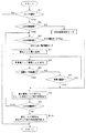
以上の車輪速復帰制御は、具体的には、ハイブリッドコントローラ70で所定時間毎に実行される図6の車輪速復帰制御ルーチンによって実施される。以下、図6のフローチャートに示す車輪速復帰制御ルーチンについて説明する。
Specifically, the wheel speed return control described above is performed by a wheel speed return control routine of FIG. 6 executed by the
この車輪速復帰制御ルーチンにおいては、最初のステップS1で、ブレーキコントローラ60からのブレーキ信号の入力の有無を調べる。そして、ブレーキ信号が入力されておらず、運転者によるブレーキ操作がなされていないときには、ブレーキ信号の入力待ちとなり、ブレーキ信号が入力されたとき、ステップS2へ進む。
In this wheel speed return control routine, the presence or absence of a brake signal input from the
ステップS2では、ブレーキコントローラ60からABS作動信号が入力されているか否かを調べる。ABS作動信号が入力されていないとき、すなわち、ブレーキ時の車輪ロックが発生していないときには、「回生制動制御モード」ルーチンへ移行し、ABS作動信号が入力されたとき、すなわち、ブレーキ時に車輪ロックが発生したときには、ステップS3へ進み、ABS作動状態(ABS制御モード)を調べる。
In step S <b> 2, it is checked whether an ABS operation signal is input from the
その結果、4輪の全てが減圧モードでないときには、ステップS2からステップS8へジャンプし、少なくとも1輪が減圧モードのとき、ステップS2からステップS4へ進んで回生トルクを零とする回生トルク零化指令を出力し、減圧モード下にある車輪の回生を中止した後、ステップS5で車輪速アップ駆動トルク指令を出力する。この車輪速アップ駆動トルク指令は、前述した目標モータ回転数ωMと駆動トルクTMMとのフィードフォワード制御により、ロックした車輪の車輪速度をアップして回転復帰を促進する制御指令である。 As a result, when all of the four wheels are not in the decompression mode, the routine jumps from step S2 to step S8. When at least one wheel is in the decompression mode, the routine proceeds from step S2 to step S4, and the regeneration torque nulling command is set to zero Is output and wheel regeneration under the decompression mode is stopped, and then a wheel speed up drive torque command is output in step S5. This wheel speed up drive torque command is a control command for increasing the wheel speed of the locked wheel and promoting the rotation return by the feedforward control of the target motor rotational speed ωM and the drive torque TMM described above.
その後、ステップ6へ進み、モータ回転数が目標モータ回転数ωMに達したか否かを判定する。モータ回転数が目標モータ回転数ωMに達していない場合には、ステップS7で駆動トルクTMMを与える時間として設定した時間tの経過を待ち、時間tが経過したとき、或いはモータ回転数が目標モータ回転数ωMに達したときには、ステップS8へ進み、
微小駆動トルクTMminを与える微小駆動トルク指令を出力して駆動系の機械的な応答遅れを補償すると共に、ブレーキコントローラ60にブレーキ液圧アップ指令信号を出力して微小駆動トルクTMmin発生中のブレーキ制御圧を増圧し、運転者がスリップを察知してブレーキペダル34の踏み込みを緩めた場合にも、ABS加圧時の車輪制動力を通常のABS制御時と同様に確保する。
Thereafter, the process proceeds to step 6 to determine whether or not the motor rotational speed has reached the target motor rotational speed ωM. If the motor rotational speed has not reached the target motor rotational speed ωM, it waits for the elapse of time t set as the time for applying the drive torque TMM in step S7, and when the time t elapses or the motor rotational speed is the target motor. When the rotational speed ωM is reached, the process proceeds to step S8.
A minute drive torque command that gives a minute drive torque TMmin is output to compensate for a mechanical response delay of the drive system, and a brake fluid pressure up command signal is output to the
その後、ステップS9へ進み、ABS作動信号の有無からABS作動が解除されたか否かを判断する。そして、依然としてABSが作動している場合には、ステップS3へ戻って以上の処理を繰り返し、ABS作動が解除されたとき、ステップS10へ進んで、駆動トルクTMM及び微小駆動トルクTMminによる補正を解除する補正トルク解除信号を出力すると共に、微小駆動トルクTMminに対応したブレーキ制御圧の増圧を解除する液圧アップ指令解除信号をブレーキコントローラ60に出力し、ルーチンを抜ける。
Then, it progresses to step S9 and it is judged whether the ABS operation | movement was cancelled | released from the presence or absence of the ABS operation signal. If the ABS is still operating, the process returns to step S3 and repeats the above processing. When the ABS operation is canceled, the process proceeds to step S10 to cancel the correction by the driving torque TMM and the minute driving torque TMmin. And a hydraulic pressure up command release signal for releasing the increase in brake control pressure corresponding to the minute drive torque TMmin is output to the
以上のように、本実施の形態においては、ABSを併設した既存の電子制御ブレーキシステムを利用しながら、制動中におけるABS作動時に、各輪のABS作動状態(減圧・保持・加圧モード)の情報に基づいて、スリップした(ロックした)車輪に比較的大きな駆動トルクを与えて車輪の回転復帰を早め、また、回転復帰後も、微小駆動トルクを与えると共に、この微小駆動トルク分だけブレーキ制御圧を高めることにより、十分なブレーキ性能を確保しつつ、ABS制御応答性とABS作動時の方向安定性とを向上することができる。 As described above, in the present embodiment, the ABS operating state (depressurization / holding / pressurization mode) of each wheel is applied at the time of ABS operation during braking while using the existing electronically controlled brake system provided with ABS. Based on the information, a relatively large driving torque is applied to the slipped (locked) wheel to speed up the wheel rotation recovery. After the rotation recovery, a minute driving torque is applied and the brake control is performed by this minute driving torque. By increasing the pressure, it is possible to improve the ABS control responsiveness and the directional stability during ABS operation while ensuring sufficient braking performance.
尚、自動ブレーキにより車両のヨー挙動を制御するスタビリティコントロール装置を有する電動車両では、スタビリティコントロール制御終了時の車輪速復帰を早め、ヨー収束性を向上することが可能である。 In an electric vehicle having a stability control device that controls the yaw behavior of the vehicle by automatic braking, it is possible to speed up the wheel speed return at the end of the stability control control and improve the yaw convergence.
5 フロントモータ
7 リヤモータ
60 ブレーキコントローラ
65 ABS制御部
70 ハイブリッドコントローラ
71a 回生トルク演算部
71b 目標モータ回転数演算部
SV1〜SV4 ABS加圧弁
SV5〜SV8 ABS減圧弁
IW 回転慣性
TMM 駆動トルク
TMmin 微小駆動トルク
V 推定車速
i 減速比
ω 目標車輪速度
ωM 目標モータ回転数
ω0 実車輪速度
5
Claims (5)
上記車輪がロック状態と判定したときの車体速度を車輪速度に基いて推定し、推定した車体速度に相当する目標車輪速度に上記モータから車軸までの減速比を乗算して上記モータの目標回転数を設定する手段と、
上記アンチロックブレーキシステムが作動して上記車輪のブレーキ圧力を減圧する減圧モードにあるとき、上記モータによる回生制動を中止し、ロック状態にある上記車輪の回転慣性に上記目標車輪速度と実車輪速度との偏差を乗算して求めた駆動トルクを上記モータに発生させてロック状態にある上記車輪の車輪速度をアップさせる手段とを備えたことを特徴とする電動車両の駆動力制御装置。 An electronically controlled brake system that transmits at least the driving force of the motor to the wheels and electronically controls the pressure of the brake system, and an anti-lock brake system that determines the lock state of the wheels by braking and adjusts the brake pressure of the wheels A driving force control device for an electric vehicle comprising:
The vehicle body speed when the wheel is determined to be locked is estimated based on the wheel speed, and the target wheel speed corresponding to the estimated vehicle body speed is multiplied by the reduction ratio from the motor to the axle. A means of setting
When it the anti-lock braking system is activated in vacuum mode for reducing the brake pressure of the wheel, stop the regenerative braking by the motor, Lock the target wheel speed rotational inertia of the wheel which is in click state and the actual A drive force control device for an electric vehicle, comprising: means for increasing a wheel speed of the wheel in a locked state by causing the motor to generate a drive torque obtained by multiplying a deviation from the wheel speed .
Priority Applications (1)
| Application Number | Priority Date | Filing Date | Title |
|---|---|---|---|
| JP2005156087A JP4732003B2 (en) | 2005-05-27 | 2005-05-27 | Driving force control device for electric vehicle |
Applications Claiming Priority (1)
| Application Number | Priority Date | Filing Date | Title |
|---|---|---|---|
| JP2005156087A JP4732003B2 (en) | 2005-05-27 | 2005-05-27 | Driving force control device for electric vehicle |
Publications (2)
| Publication Number | Publication Date |
|---|---|
| JP2006333665A JP2006333665A (en) | 2006-12-07 |
| JP4732003B2 true JP4732003B2 (en) | 2011-07-27 |
Family
ID=37554758
Family Applications (1)
| Application Number | Title | Priority Date | Filing Date |
|---|---|---|---|
| JP2005156087A Expired - Fee Related JP4732003B2 (en) | 2005-05-27 | 2005-05-27 | Driving force control device for electric vehicle |
Country Status (1)
| Country | Link |
|---|---|
| JP (1) | JP4732003B2 (en) |
Families Citing this family (7)
| Publication number | Priority date | Publication date | Assignee | Title |
|---|---|---|---|---|
| JP5401967B2 (en) * | 2008-12-17 | 2014-01-29 | 日産自動車株式会社 | Drive wheel lock prevention device for electric vehicle |
| JP5856465B2 (en) * | 2011-12-16 | 2016-02-09 | トヨタ自動車株式会社 | vehicle |
| JP5797573B2 (en) * | 2012-01-27 | 2015-10-21 | 日立オートモティブシステムズ株式会社 | Vehicle control device |
| JP5443571B2 (en) * | 2012-09-27 | 2014-03-19 | 日立オートモティブシステムズ株式会社 | Brake control device |
| JP6160199B2 (en) * | 2013-04-18 | 2017-07-12 | 日産自動車株式会社 | Electric vehicle braking control system |
| JP5884245B2 (en) | 2013-06-19 | 2016-03-15 | オートリブ日信ブレーキシステムジャパン株式会社 | Brake hydraulic pressure control device for vehicles |
| JP2025089072A (en) * | 2023-12-01 | 2025-06-12 | トヨタ自動車株式会社 | Electric vehicle control device |
Family Cites Families (7)
| Publication number | Priority date | Publication date | Assignee | Title |
|---|---|---|---|---|
| JPH05270387A (en) * | 1992-03-27 | 1993-10-19 | Toyota Motor Corp | Braking controller for electric vehicle |
| JP3129126B2 (en) * | 1994-12-09 | 2001-01-29 | 三菱自動車工業株式会社 | Shift control method for electric vehicle |
| JP3011068B2 (en) * | 1995-09-07 | 2000-02-21 | トヨタ自動車株式会社 | Power plant for vehicles |
| JPH10322803A (en) * | 1997-05-12 | 1998-12-04 | Toyota Motor Corp | Vehicle braking system |
| JP3536634B2 (en) * | 1997-12-25 | 2004-06-14 | 日産自動車株式会社 | Hybrid vehicle control device |
| JP3582521B2 (en) * | 2002-08-13 | 2004-10-27 | 日産自動車株式会社 | Driving force control device for four-wheel drive vehicle |
| JP4089359B2 (en) * | 2002-09-03 | 2008-05-28 | 株式会社日立製作所 | Control device for hybrid vehicle |
-
2005
- 2005-05-27 JP JP2005156087A patent/JP4732003B2/en not_active Expired - Fee Related
Also Published As
| Publication number | Publication date |
|---|---|
| JP2006333665A (en) | 2006-12-07 |
Similar Documents
| Publication | Publication Date | Title |
|---|---|---|
| JP5983871B2 (en) | Brake device | |
| EP1067032B1 (en) | Vehicular brake system | |
| JPWO2014184840A1 (en) | Brake device | |
| CN101242981A (en) | Energy regeneration in a hybrid vehicle having a hydraulic or pneumatic brake device | |
| JP6164045B2 (en) | Vehicle braking force control method | |
| US8600638B2 (en) | Vehicle stabilization controlling apparatus | |
| JP2009166656A (en) | Brake control system | |
| JPH05178188A (en) | Traction controller for vehicle | |
| JP4935760B2 (en) | Brake control device | |
| JP4732003B2 (en) | Driving force control device for electric vehicle | |
| JP3425727B2 (en) | Automatic braking system for vehicles | |
| JPH1118208A (en) | Vehicle | |
| JP4725281B2 (en) | Vehicle braking force holding device and vehicle braking force holding method | |
| JP6745709B2 (en) | Brake control device | |
| JP2012131299A (en) | Brake device for vehicle | |
| JP4561588B2 (en) | Vehicle braking force holding device and vehicle braking force holding method | |
| JP5895480B2 (en) | Brake control device for vehicle | |
| JP4677878B2 (en) | Braking force holding device for vehicle | |
| JP5209589B2 (en) | Brake hydraulic pressure control device for vehicles | |
| JP2009090774A (en) | Brake fluid pressure control device and motorcycle brake fluid pressure control device | |
| CN107249942A (en) | Vehicle Behavior- Based control device | |
| KR101316584B1 (en) | Vehicles braking system and method of controlling the same | |
| JP6127364B2 (en) | Brake control device for vehicle | |
| JP2007055478A (en) | Multi-axis vehicle and steering control device thereof | |
| JP2926628B2 (en) | Energy regenerative braking system for vehicles |
Legal Events
| Date | Code | Title | Description |
|---|---|---|---|
| A621 | Written request for application examination |
Free format text: JAPANESE INTERMEDIATE CODE: A621 Effective date: 20080512 |
|
| A977 | Report on retrieval |
Free format text: JAPANESE INTERMEDIATE CODE: A971007 Effective date: 20100917 |
|
| A131 | Notification of reasons for refusal |
Free format text: JAPANESE INTERMEDIATE CODE: A131 Effective date: 20101012 |
|
| A521 | Request for written amendment filed |
Free format text: JAPANESE INTERMEDIATE CODE: A523 Effective date: 20101208 |
|
| A01 | Written decision to grant a patent or to grant a registration (utility model) |
Free format text: JAPANESE INTERMEDIATE CODE: A01 Effective date: 20110405 |
|
| A01 | Written decision to grant a patent or to grant a registration (utility model) |
Free format text: JAPANESE INTERMEDIATE CODE: A01 |
|
| A61 | First payment of annual fees (during grant procedure) |
Free format text: JAPANESE INTERMEDIATE CODE: A61 Effective date: 20110420 |
|
| FPAY | Renewal fee payment (event date is renewal date of database) |
Free format text: PAYMENT UNTIL: 20140428 Year of fee payment: 3 |
|
| R150 | Certificate of patent or registration of utility model |
Free format text: JAPANESE INTERMEDIATE CODE: R150 |
|
| R250 | Receipt of annual fees |
Free format text: JAPANESE INTERMEDIATE CODE: R250 |
|
| S531 | Written request for registration of change of domicile |
Free format text: JAPANESE INTERMEDIATE CODE: R313531 |
|
| R350 | Written notification of registration of transfer |
Free format text: JAPANESE INTERMEDIATE CODE: R350 |
|
| R250 | Receipt of annual fees |
Free format text: JAPANESE INTERMEDIATE CODE: R250 |
|
| R250 | Receipt of annual fees |
Free format text: JAPANESE INTERMEDIATE CODE: R250 |
|
| LAPS | Cancellation because of no payment of annual fees |