JP4729308B2 - Transfer car for metal coil - Google Patents
Transfer car for metal coil Download PDFInfo
- Publication number
- JP4729308B2 JP4729308B2 JP2004556093A JP2004556093A JP4729308B2 JP 4729308 B2 JP4729308 B2 JP 4729308B2 JP 2004556093 A JP2004556093 A JP 2004556093A JP 2004556093 A JP2004556093 A JP 2004556093A JP 4729308 B2 JP4729308 B2 JP 4729308B2
- Authority
- JP
- Japan
- Prior art keywords
- support saddle
- cylinder
- lifting
- lifting mechanism
- scissors
- Prior art date
- Legal status (The legal status is an assumption and is not a legal conclusion. Google has not performed a legal analysis and makes no representation as to the accuracy of the status listed.)
- Expired - Lifetime
Links
Images


Classifications
-
- B—PERFORMING OPERATIONS; TRANSPORTING
- B21—MECHANICAL METAL-WORKING WITHOUT ESSENTIALLY REMOVING MATERIAL; PUNCHING METAL
- B21C—MANUFACTURE OF METAL SHEETS, WIRE, RODS, TUBES OR PROFILES, OTHERWISE THAN BY ROLLING; AUXILIARY OPERATIONS USED IN CONNECTION WITH METAL-WORKING WITHOUT ESSENTIALLY REMOVING MATERIAL
- B21C47/00—Winding-up, coiling or winding-off metal wire, metal band or other flexible metal material characterised by features relevant to metal processing only
- B21C47/24—Transferring coils to or from winding apparatus or to or from operative position therein; Preventing uncoiling during transfer
-
- B—PERFORMING OPERATIONS; TRANSPORTING
- B65—CONVEYING; PACKING; STORING; HANDLING THIN OR FILAMENTARY MATERIAL
- B65H—HANDLING THIN OR FILAMENTARY MATERIAL, e.g. SHEETS, WEBS, CABLES
- B65H19/00—Changing the web roll
- B65H19/10—Changing the web roll in unwinding mechanisms or in connection with unwinding operations
- B65H19/12—Lifting, transporting, or inserting the web roll; Removing empty core
Landscapes
- Engineering & Computer Science (AREA)
- Mechanical Engineering (AREA)
- Winding, Rewinding, Material Storage Devices (AREA)
- Platform Screen Doors And Railroad Systems (AREA)
- Handcart (AREA)
- Replacement Of Web Rolls (AREA)
- Rollers For Roller Conveyors For Transfer (AREA)
- Electroluminescent Light Sources (AREA)
- Acyclic And Carbocyclic Compounds In Medicinal Compositions (AREA)
- Fats And Perfumes (AREA)
- Superconductors And Manufacturing Methods Therefor (AREA)
- Intermediate Stations On Conveyors (AREA)
- Types And Forms Of Lifts (AREA)
Abstract
Description
本発明は、基礎フレームの上で、直線状の垂直方向案内機構に沿って支持サドルを持上げおよび降下するための手段を備える、搬送区間に沿って駆動装置によって移動可能な台架を有する、金属コイルのための、搬送設備内における移送車に関する。 The present invention provides a metal having a platform movable by a drive device along a conveying section, comprising means for lifting and lowering a support saddle along a straight vertical guide mechanism on a base frame The present invention relates to a transfer vehicle in a transfer facility for a coil.
金属コイルを搬入、および搬出するために、例えばストリップ処理設備内において、いわゆるコイル移送車が使用される。
公知の実施形態は、例えば、支持サドルの中央の案内機構、並びに、昇降機構を操作するための2つの液圧シリンダーを装備している。
In order to carry metal coils in and out, so-called coil transfer vehicles are used, for example, in strip processing equipment.
The known embodiment is equipped, for example, with a central guide mechanism of the support saddle and two hydraulic cylinders for operating the lifting mechanism.
昇降機構の案内機構は、円形案内機構として、および矩形案内機構として形成されており、且つ、通常は、基礎部内においてこの案内機構のために設けられた案内スリット内において走行する。この基礎部は、場合によっては、極めて深くなくてはならず、且つ、事故を回避するために、場合によってはコイル移送車によって連行されるカバー要素を有する安全保護のカバーを必要とする。 The guide mechanism of the elevating mechanism is formed as a circular guide mechanism and a rectangular guide mechanism, and normally travels in a guide slit provided for the guide mechanism in the base portion. This foundation must in some cases be very deep and, in order to avoid accidents, requires a safety cover with a cover element that is sometimes entrained by a coiled vehicle.
更に公知の実施形態は、支持サドルを案内するため、および、昇降運動の操作のために、いわゆるシザーズタイプ昇降テーブルを使用している。このシステムの場合、持上げのために必要な昇降シリンダーが、このシザーズタイプ昇降機構システムに作用している。このコイル用車両は、確かに比較的に平らに構成されており、且つ、基礎部内において必要な開口部が、相応して比較的に小さいという結果になる。しかしながら、このシザーズタイプ昇降機構システムにおける液圧シリンダーの都合の悪い力作用、および、直線状でない昇降運動は、欠点と見なされる。 Further known embodiments use a so-called scissors-type lifting table for guiding the support saddle and for operating the lifting movement. In the case of this system, the lifting cylinder necessary for lifting is acting on this scissors type lifting mechanism system. This coil vehicle is indeed configured to be relatively flat and the result is that the required opening in the base is correspondingly relatively small. However, the inconvenient force action of the hydraulic cylinder and the non-linear lifting motion in this scissor type lifting mechanism system is considered a drawback.
このコイル移送車の更に公知のバリエーションは、偏心的に、実荷重物と並んで設けられた昇降システムを装備している。このシステムの利点は、十分に平らな構造様式、および、基礎溝部の放棄にある。しかしながら、都合の悪い力作用、およびこの実荷重物の限定された外からの取り扱い可能性に、不利な影響を及ぼす。 A further known variation of this coil transfer vehicle is eccentrically equipped with a lifting system provided alongside the actual load. The advantage of this system is a sufficiently flat construction style and abandonment of the base groove. However, it has a detrimental effect on the unfavorable force action and the limited external handleability of this actual load.
ヨーロッパ特許出願公開第0 569 719号明細書(特許文献1)は、
直線走行および曲線走行ためのエアークッション車両を有する、コイル移送システムが記載されており、このコイル移送システムの場合、このエアークッション車両が、横方向移動のために、このエアークッション車両の長手方向側面に、機械的な、交互に右側または左側で操作可能な側面ガイドを有しており、これら側面ガイドに、案内ガイドが所属して設けられている。
European Patent Application No. 0 569 719 (Patent Document 1)
A coil transfer system is described having an air cushion vehicle for straight and curved travel, in the case of this coil transfer system, the air cushion vehicle has a longitudinal side surface for the lateral movement. In addition, there are side guides that can be operated mechanically alternately on the right side or the left side, and guide guides belong to these side guides.
ヨーロッパ特許出願公開第0 061 557号明細書(特許文献2)は、薄板
コイルのための搬送設備が記載されており、この搬送設備が、搬送区間に沿って、駆動装置を用いて移動可能なコイル用車両を有している。このコイル車両の正確な位置検出を、この搬送区間の上で保障するために、コイル車両駆動装置が、この搬送区間に沿って敷設された、このコイル車両の駆動可能な歯車と噛み合うラックから成り、その際、このラックが、長さ測定装置のためのインクリメンタルスケールとして使用され、この長さ測定装置が、このインクリメンタルスケールのための走査ユニット、および、この走査ユニットの走査パルスのための少なくとも1つの計数装置を備えている。
従って、この上記の公知技術を出発点として、本発明の根底をなす課題は、請求項1の上位概念において言及された様式の、搬送区間に沿って移動可能な台架有する、薄板コイルのための搬送設備の、一方では上述のシステムの利点を兼ね備え、他方ではしかしながら上記の欠点を回避し、且つその上更に低廉に製造され得る、移送車の改良された構造を提案することである。
Therefore, starting from this known technique, the problem underlying the present invention is that of a thin plate coil having a platform movable in the conveying section in the manner referred to in the superordinate concept of
この課題の解決は、本発明でもって、
この板状の基礎フレームの上で、直線状の垂直方向案内機構のために、シザーズタイプ昇降機構が設けられていること、
その際、このシザーズタイプ昇降機構が、単にこの支持サドルの同期調整および案内の役目だけを引き受けるように形成されていること、
このシザーズタイプ昇降機構が、この案内のために如何なる昇降運動力も必要としないこと、
この支持サドルを持上げおよび降下するために、直接的にこの支持サドルに、相互の間隔において接続する2つの昇降シリンダーユニット(Hubzylinder)が駆動装置として設けられており、該昇降シリンダーユニットを用いて、上記支持サドルが直接的に昇降されること、
大きな昇降高さのために、上記昇降シリンダーユニットが、
先ず始めに繰り出される、並列に配設された2つのテレスコープ式シリンダーを備える、シリンダー二重配設部から成る、半分の昇降高さを有する下側の構造部と、
引き続いて更に全ストロークに至るまで繰り出される、上記シリンダー二重配設部の上に支持された1つのテレスコープ式シリンダーから成る、上側の構造部とから構成されていること、
シザーズタイプ昇降機構の上側の部分が、実荷重物のための、支持サドルとして形成されていること、
基礎フレームの下側に沿って、駆動手段を備える走行機構が設けられていること、および、
走行機構として、市販のシステムが使用されることによって達成する。
鋼スラブの代わりに、同様に溶接された成形鋼フレームも、基礎フレームとして使用され得る。
The solution to this problem is the present invention.
On this plate-shaped foundation frame, a scissors type lifting mechanism is provided for a linear vertical guide mechanism,
At that time, the scissors type lifting mechanism is formed so as to accept only the function of the synchronous adjustment and guidance of the support saddle,
The scissors-type lifting mechanism does not require any lifting force for this guidance;
In order to lift and lower the support saddle, two lifting cylinder units (Hubzylinder) connected directly to the supporting saddle at a distance from each other are provided as driving devices, and using the lifting cylinder unit, The support saddle is raised and lowered directly;
Due to the large lifting height, the lifting cylinder unit
A lower structure part having a half elevation height, comprising a double cylinder arrangement part, comprising two telescopic cylinders arranged in parallel, which are first drawn out;
An upper structure composed of one telescoping cylinder supported on the cylinder double arrangement portion, which is subsequently drawn out to the full stroke.
The upper part of the scissors type lifting mechanism is formed as a support saddle for an actual load,
A traveling mechanism provided with driving means is provided along the lower side of the base frame, and
This is achieved by using a commercially available system as the traveling mechanism .
Instead of a steel slab, a similarly welded shaped steel frame can also be used as a base frame.
利点でもって、この構造様式の場合、支持サドルの両方の側において、有利な力作用が効果を現す。この装置は、更に、基礎部内において如何なるスリット案内部も必要では無く、且つ、更に、実荷重物への限定されない外からの取り扱い可能性を保障する。 With this advantage, in this construction mode, an advantageous force action takes effect on both sides of the support saddle. In addition, this device does not require any slit guides in the foundation and further ensures unrestricted handleability from the outside to the actual load.
合目的に、シザーズタイプ昇降機構の上側の部分は、実荷重物のための、支持サドルとして形成されている。 Conveniently, the upper part of the scissors type lifting mechanism is formed as a support saddle for the actual load.
シザーズタイプ昇降機構の移動可能な部分は、有利には、例えば市販の直線状案内機構において案内されている。従って、低廉の、且つ堅牢な、圧延機に適合した、支持サドルの案内機構が得られる。
この全システムは、その際、単に4つの主部分、即ち、昇降機構、垂直方向案内機構、走行機構、および、液圧的な装置だけから成っている。
更に、昇降運動は、直線的に(linear)、且つこのシザーズタイプ昇降機構の現在の位置に依存せずに行われる。
このシザーズタイプ昇降機構システムは、従って、単にこの支持サドルの同期調整および案内の役目だけを引き受けねばならず、且つ、如何なる昇降運動力も、案内のために必要としない。走行機構として、概念上完全に購入されたシステムが、場合によってはほんの少しだけ適合において使用される。
同様に、特殊ケーシング、および規格部材の組込み構造体を有する構成も可能である。
更なる利点は、液圧シリンダー、もしくは、この液圧シリンダーの一部分が、高圧モデルシリーズ(Hochdruckbaureihe)の旧来のシリンダーであることによって与えられる。構造空間、およびコストを節約するために、その際、有利には、高圧液圧装置(280bar)でもって作動される。
The movable part of the scissors-type lifting mechanism is advantageously guided, for example, in a commercially available linear guide mechanism. Accordingly, an inexpensive and robust guide mechanism for the supporting saddle adapted to the rolling mill can be obtained.
The entire system then consists of only four main parts: a lifting mechanism, a vertical guide mechanism, a traveling mechanism, and a hydraulic device.
Furthermore, the lifting movement is performed linearly and independent of the current position of the scissor type lifting mechanism.
The scissor-type lifting mechanism system must therefore only take on the synchronous adjustment and guiding role of the support saddle, and no lifting force is required for guidance. As a travel mechanism, a system that is conceptually completely purchased is used in the adaptation in some cases.
Similarly, a configuration having a special casing and a built-in structure of standard members is also possible.
A further advantage is given by the fact that the hydraulic cylinder, or part of this hydraulic cylinder, is an old cylinder of the high-pressure model series (Hochdruckbaureihe). In order to save construction space and costs, it is then advantageously operated with a high-pressure hydraulic device (280 bar).
本発明の、即ちコイル移送車の諸実施形態は、従属請求項に相応して行われている。 The embodiments of the invention, i.e. the coil transfer wheel, are carried out in accordance with the dependent claims.
本発明の更なる詳細、特徴、および利点は、図において概略的に図示された実施例の、以下の説明から与えられる。 Further details, features and advantages of the invention are given from the following description of an embodiment schematically illustrated in the figures.
図1は、基礎フレーム3の上で、直線状の垂直方向案内機構5に沿って支持サドル4を持上げおよび降下するための手段を備える、搬送区間1に沿って駆動装置によって移動可能な台架2を有する、搬送設備内における、詳細には図示されていない金属コイルのための移送車を示している。この搬送設備は、そのことが図4および図4aにおいて示されているように、その他に、載置ステーション17、フロアローラーステーション18、軌道19、および秤量ステーション20から成っている。
コイル移送車の場合、ここで、基礎フレーム3として、鋼スラブが使用されており、この鋼スラブの上で、直線状の垂直方向案内機構5のために、シザーズタイプ昇降機構6が設けられており、その際、この支持サドル4を持上げおよび降下するために、駆動装置2として、直接的にこの支持サドルに、相互の間隔において接続する2つの昇降シリンダーユニット7が設けられている。
このシザーズタイプ昇降機構6の上側の部分は、実荷重物のための、例えば金属コイルのための、支持サドル4として形成されている。このシザーズタイプ昇降機構6の移動可能な部分は、市販の直線状案内機構においてスライドシュー8を用いて案内されている。従って、低廉の、且つ堅牢な、圧延機に適合した、支持サドル4の案内機構が得られる。この全システムは、その際、単に4つの主部分だけから成っている。
この昇降機構6を操作するために、2つの液圧シリンダー7は、直接的に、この支持サドル4を接続している。従って、昇降運動は、直線的に(linear)、且つこの支持サドル4の現在の位置に依存せずに行われる。その際に、このシザーズタイプ昇降機構システム6は、単にこの支持サドル4の同期調整および案内の役目だけを引き受けねばならず、且つ、如何なる昇降運動力の動力伝達も必要としない。
FIG. 1 shows a pedestal that can be moved by a drive device along a
In the case of the coil transfer vehicle, here, a steel slab is used as the foundation frame 3, and a scissors type lifting mechanism 6 is provided on the steel slab for the linear vertical guide mechanism 5. In this case, in order to lift and lower the
The upper part of the scissors type lifting mechanism 6 is formed as a
In order to operate the lifting mechanism 6, the two
コイル移送車は、同行可能な液圧ステーション9を備えており、且つ、この液圧ステーションが、エネルギー入力のために、ケーブル牽引チェーン10と接続されている。 The coil transfer vehicle is provided with a hydraulic station 9 that can be accompanied, and this hydraulic station is connected to a cable traction chain 10 for energy input.
更に、基礎フレーム3の下側に沿って、駆動手段を備える走行機構11が設けられている。その際、走行機構として、市販のシステムが使用され得ることの利点が与えられる。
Furthermore, a
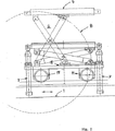
図3は、断面図において、両側の走行レール15上で走行方向において設けられている、走行機構11有する、コイル移送車を示している。この図から、同様に昇降シリンダーユニット7の中央配設、および、それぞれ1つの支持サドル4とのこの昇降シリンダーユニットの組立ても見て取れる。この図示は、印象的に、移送車の相対的に低い構造様式を示しており、この移送車が、ただ中央側だけに、この移送車の機能要素の、最適な外からの取り扱い可能性における基礎部において、平坦な走行ダクトを必要とする。
FIG. 3 shows a coil transfer vehicle having a
図4は、軌道19を有する搬送設備の全配設、および、この左側の端部における、そのコイル移送車のシザーズタイプ昇降機構6および走行機構11を有する、側方眺望における、コイル移送車を示している。
この搬送設備は、載置ステーション17、フロアローラーステーション18、ケーブル牽引チェーン10を有する軌道19、並びに、端部側に秤量ステーション20を備えている。
図4aは、平面図において、この全体の設備を示している。
このコイル移送車は、このコイル移送車に強固に設けられた、同行可能な液圧ステーション9を備えている。この液圧ステーションは、ケーブル牽引チェーン10と、エネルギー入力のために、導電的に結合されている。
比較的に大きな昇降道程の場合、昇降シリンダーユニットの長さが、全システムの構造高さを規定する。このことによって与えられる、この昇降シリンダーユニットの大きな構造高さを回避するために、図5内において、純粋に原理的に図示された、昇降システムの配設、および実施形態は、シリンダー二重配設部12でもって行われる。その際、支持サドル4の案内機構との協働で、シザーズタイプ昇降機構6において、比較的に低い構造高さが得られる。
FIG. 4 shows the entire arrangement of the transfer equipment having the
This transport facility includes a mounting
FIG. 4a shows this entire installation in plan view.
The coil transfer vehicle includes a hydraulic station 9 that can be accompanied by the coil transfer vehicle. This hydraulic station is conductively coupled to the cable traction chain 10 for energy input.
In the case of a relatively large lift path, the length of the lift cylinder unit defines the structural height of the entire system. In order to avoid the large structural height of this lifting cylinder unit provided by this, the arrangement and embodiment of the lifting system, which is illustrated purely in principle in FIG. This is performed by the
シリンダーの旧来の配設の場合、昇降のために必要な道程は、全面的に、このシリンダー内において提供されねばならない。このシリンダーの構造長さが、この車両の構造高さを上まわる限りは、従って、この昇降高さはコイル移送車の全高さを規定する。
シリンダー二重配設部12およびテレスコープ式シリンダー14の、図5に従う、本発明による配設によって、2つ、または多数のシリンダーの個別ストロークは、全ストロークが、原理略図である図5に従い、複雑でない手段でもって与えられるように、互いの中へ入れ子式にされる。
支持サドルの上方へのストロークが行われるべき場合、先ず始めに、1つのシリンダー列12が繰り出される。引き続いて、上側の構造部13において、第2の列14が、更に、全ストロークに至るまで繰り出される。
略図である図5から認識できるように、従って、昇降シリンダーユニットのコンパクトな配設が与えられる。
図6は、上記の目的のための、シリンダー二重配設部12の上側の構造部13からの繰り出しの際の、シリンダー二重配設部12のテレスコープ式シリンダー14の配設を示している。
図7は、断面図における、支持サドル4の上で、薄板コイル16の形状における荷重を有する、載置ステーション17を示している。この支持サドルは、降下された位置において、実線の矢印4でもって、および、上昇された位置において、破線の矢印4でもって示されている。
図8は、移送車の中心面内において昇降シリンダーユニット7の配設を有する、平面図における載置ステーション17を示している。
In the case of the classic arrangement of the cylinder, the path required for raising and lowering must be provided entirely within this cylinder. As long as the structural length of the cylinder exceeds the structural height of the vehicle, the lift height thus defines the total height of the coil transfer vehicle.
With the arrangement according to the invention of the
If an upward stroke of the support saddle is to be made, first one
As can be appreciated from FIG. 5, which is a schematic, a compact arrangement of the lifting cylinder unit is thus provided.
FIG. 6 shows the arrangement of the telescoping cylinder 14 of the cylinder
FIG. 7 shows a mounting
FIG. 8 shows the mounting
フロアローラーステーション18の実施形態は、図9および10内において、断面図および平面図において図示されている。
An embodiment of the
および要するに、移送設備は、断面図および平面図における、図11および12による走行区間19の端部において、秤量ステーション20を備えている。
この秤量ステーション20は、図13および14内において、断面図および平面図において図示されている。
And in short, the transfer equipment comprises a weighing
This weighing
1 搬送区間
2 台架
3 基礎フレーム
4 支持サドル
5 垂直方向案内機構
6 シザーズタイプ昇降機構
7 昇降シリンダーユニット
8 スライドシュー
9 液圧ステーション
10 ケーブル牽引チェーン
11 走行機構
12 シリンダー二重配設部
13 上側の構造部
14 テレスコープ式シリンダー
15 走行レール
16 荷重(薄板コイル)
17 載置ステーション
18 フロアローラーステーション
19 軌道
20 秤量ステーション
DESCRIPTION OF
17
Claims (3)
この板状の基礎フレーム(3)の上で、直線状の垂直方向案内機構(5)のために、シザーズタイプ昇降機構(6)が設けられていること、
その際、このシザーズタイプ昇降機構(6)が、単にこの支持サドル(4)の同期調整および案内の役目だけを引き受けるように形成されていること、
このシザーズタイプ昇降機構(6)が、この案内のために如何なる昇降運動力も必要としないこと、
この支持サドル(4)を持上げおよび降下するために、直接的にこの支持サドルに、相互の間隔において接続する2つの昇降シリンダーユニット(7)が駆動装置として設けられており、該昇降シリンダーユニット(7)を用いて、上記支持サドル(4)が直接的に昇降されること、
大きな昇降高さのために、上記昇降シリンダーユニット(7)が、
先ず始めに繰り出される、並列に配設された2つのテレスコープ式シリンダーを備える、シリンダー二重配設部(12)から成る、半分の昇降高さを有する下側の構造部と、
引き続いて更に全ストロークに至るまで繰り出される、上記シリンダー二重配設部(12)の上に支持された1つのテレスコープ式シリンダー(14)から成る、上側の構造部とから構成されていること、
シザーズタイプ昇降機構(6)の上側の部分が、実荷重物のための、支持サドル(4)として形成されていること、
基礎フレーム(3)の下側に沿って、駆動手段を備える走行機構(11)が設けられていること、および、
走行機構(11)として、市販のシステムが使用されることを特徴とするコイル移送車。On the base frame (3), moved by the drive device along the transport section (1) with means for lifting and lowering the support saddle (4) along the straight vertical guide mechanism (5) In a coil transport vehicle for transport equipment for metal coils, having a possible cradle (2),
A scissors-type lifting mechanism (6) is provided on the plate-shaped foundation frame (3) for the linear vertical guide mechanism (5).
At this time, the scissors type lifting mechanism (6) is formed so as to accept only the role of the synchronous adjustment and guidance of the support saddle (4),
The scissors-type lifting mechanism (6) does not require any lifting force for this guidance;
In order to lift and lower the support saddle (4), two lift cylinder units (7) connected directly to the support saddle at a distance from each other are provided as drive devices. 7) the support saddle (4) is lifted and lowered directly using
Due to the large lifting height, the lifting cylinder unit (7)
A lower structure having a half elevation height, consisting of a double cylinder arrangement (12) comprising two telescopic cylinders arranged in parallel, which are first fed out;
It is composed of an upper structure part consisting of one telescopic cylinder (14) supported on the cylinder double arrangement part (12), which is subsequently drawn out to the full stroke. ,
The upper part of the scissors-type lifting mechanism (6) is formed as a support saddle (4) for an actual load;
A traveling mechanism (11) provided with driving means is provided along the lower side of the base frame (3), and
A coil transfer vehicle using a commercially available system as the travel mechanism (11) .
Applications Claiming Priority (3)
| Application Number | Priority Date | Filing Date | Title |
|---|---|---|---|
| DE10256011.0 | 2002-11-30 | ||
| DE10256011A DE10256011A1 (en) | 2002-11-30 | 2002-11-30 | Transport trolleys for metal coils |
| PCT/EP2003/012036 WO2004050272A1 (en) | 2002-11-30 | 2003-10-30 | Transport car for metal coils |
Publications (3)
| Publication Number | Publication Date |
|---|---|
| JP2006507945A JP2006507945A (en) | 2006-03-09 |
| JP2006507945A5 JP2006507945A5 (en) | 2010-03-25 |
| JP4729308B2 true JP4729308B2 (en) | 2011-07-20 |
Family
ID=32308880
Family Applications (1)
| Application Number | Title | Priority Date | Filing Date |
|---|---|---|---|
| JP2004556093A Expired - Lifetime JP4729308B2 (en) | 2002-11-30 | 2003-10-30 | Transfer car for metal coil |
Country Status (16)
| Country | Link |
|---|---|
| US (1) | US7762377B2 (en) |
| EP (1) | EP1565281B1 (en) |
| JP (1) | JP4729308B2 (en) |
| KR (1) | KR101024246B1 (en) |
| CN (1) | CN100374222C (en) |
| AT (1) | ATE337865T1 (en) |
| AU (1) | AU2003276205B2 (en) |
| BR (1) | BR0316632B1 (en) |
| CA (1) | CA2507654C (en) |
| DE (2) | DE10256011A1 (en) |
| ES (1) | ES2270174T3 (en) |
| MX (1) | MXPA05005723A (en) |
| PL (1) | PL205603B1 (en) |
| RU (1) | RU2317165C2 (en) |
| TW (1) | TWI294315B (en) |
| WO (1) | WO2004050272A1 (en) |
Families Citing this family (7)
| Publication number | Priority date | Publication date | Assignee | Title |
|---|---|---|---|---|
| US7534083B2 (en) * | 2005-09-02 | 2009-05-19 | Andre Trudeau | Trailer operable in lowered and raised transport positions |
| KR100797988B1 (en) * | 2006-09-15 | 2008-01-28 | 주식회사 포스코 | Scrap coil mover |
| CN102249103A (en) * | 2011-01-11 | 2011-11-23 | 无锡美誉金属复合新材料有限公司 | Discharging trolley |
| JP5912660B2 (en) * | 2012-02-28 | 2016-04-27 | 新日鉄住金エンジニアリング株式会社 | Coil transfer system |
| WO2014111100A1 (en) | 2013-01-18 | 2014-07-24 | Sms Logistiksysteme Gmbh | Asymmetric coil support |
| CN108657713B (en) * | 2018-06-25 | 2024-03-08 | 江苏斯德雷特光纤科技有限公司 | Intelligent turnover system based on optical fiber preform production and operation method thereof |
| CN113581766B (en) * | 2021-07-08 | 2023-04-28 | 中冶南方工程技术有限公司 | Steel coil ground transportation system for inter-process transportation |
Citations (4)
| Publication number | Priority date | Publication date | Assignee | Title |
|---|---|---|---|---|
| JPS52147546A (en) * | 1976-06-03 | 1977-12-08 | Ishikawajima Harima Heavy Ind | Coil car |
| JPH11125214A (en) * | 1997-10-23 | 1999-05-11 | Copros | Twin hydraulic/pneumatic cylinder |
| JP2002019612A (en) * | 2000-07-04 | 2002-01-23 | Yamato Scient Co Ltd | Carriage for aging |
| JP2002154437A (en) * | 2000-11-20 | 2002-05-28 | Okudaya Giken:Kk | Transport dolly |
Family Cites Families (23)
| Publication number | Priority date | Publication date | Assignee | Title |
|---|---|---|---|---|
| US3370727A (en) * | 1965-11-12 | 1968-02-27 | American Sugar | Laterally adjustable conveyor |
| US3341042A (en) * | 1966-12-16 | 1967-09-12 | American Sugar | Elevator control system |
| US3534664A (en) * | 1967-09-06 | 1970-10-20 | Eaton Yale & Towne | Lift truck mast and ram assembly |
| US3619007A (en) * | 1969-06-04 | 1971-11-09 | Leco Inc | Stationary or mobile, relatively movable, load-carrying, powered members |
| US3730366A (en) * | 1971-01-04 | 1973-05-01 | Holland Hitch Co | Container lift |
| DE2200212C3 (en) | 1972-01-04 | 1980-08-14 | 7560 Gaggenau | Truck for the transport of structures |
| US3880259A (en) * | 1973-02-12 | 1975-04-29 | Autoquip Corp | Power apparatus for truck loading elevator |
| US4175644A (en) * | 1973-10-15 | 1979-11-27 | Robert Staines | Scissors lift |
| IT1037812B (en) | 1975-05-02 | 1979-11-20 | Innocenti Santeustacchio Spa | EQUIPMENT FOR FEEDING SUBSEQUENT ROLLS OF SHEET METAL TO AN UNWINDING STATION |
| GB1553107A (en) * | 1975-05-17 | 1979-09-19 | Nisso Sangyo Kk | Working base elevating apparatus |
| DE2918848A1 (en) | 1979-02-14 | 1980-08-21 | Wyhlen Ag Eisenbau | Load transport and lifting truck - has support points on slide movable into path of lifting mechanism |
| AT359458B (en) | 1979-03-22 | 1980-11-10 | Voest Alpine Ag | TROLLEY FOR CONVEYING TEMPERATURE |
| US4312619A (en) * | 1979-07-19 | 1982-01-26 | Fmc Corporation | Aircraft cargo loading method and apparatus |
| US4363380A (en) * | 1980-04-18 | 1982-12-14 | Rued Glen A | Elevator and method of lifting |
| AT368410B (en) | 1981-03-23 | 1982-10-11 | Voest Alpine Ag | CONVEYOR FOR SHEET BUNDLE |
| US4971508A (en) * | 1987-06-29 | 1990-11-20 | Tsubakimoto Chain Co. | Storage and conveyance of heavy articles |
| US5072588A (en) * | 1989-08-17 | 1991-12-17 | Eagle-Picher Industries, Inc. | Motion multiplier for use with extendable boom fork lift vehicle |
| DE4215430A1 (en) | 1992-05-11 | 1993-11-18 | Schloemann Siemag Ag | Coil transport system |
| US5636713A (en) * | 1992-08-31 | 1997-06-10 | Perkins; Rex H. | Multiple RAM assembly and recuperative drive system for hydraulic lift |
| WO1999012672A1 (en) | 1997-09-10 | 1999-03-18 | Evg Entwicklungs- U. Verwertungs-Gesellschaft Mbh | Method and facility for continuous feeding of wire-shaped material to a consumer |
| US6223885B1 (en) * | 1997-11-25 | 2001-05-01 | Captial Engineering, Inc. | Shuttle car conveyor for conveyable material |
| CN2451559Y (en) * | 2000-11-23 | 2001-10-03 | 吴南汉 | Wheel type shears frame lifting jack |
| CN2468985Y (en) * | 2001-03-08 | 2002-01-02 | 萧山市同昌机械物资有限公司 | Platform lift |
-
2002
- 2002-11-30 DE DE10256011A patent/DE10256011A1/en not_active Withdrawn
-
2003
- 2003-10-29 TW TW092129979A patent/TWI294315B/en not_active IP Right Cessation
- 2003-10-30 KR KR1020057009605A patent/KR101024246B1/en active IP Right Grant
- 2003-10-30 JP JP2004556093A patent/JP4729308B2/en not_active Expired - Lifetime
- 2003-10-30 AU AU2003276205A patent/AU2003276205B2/en not_active Ceased
- 2003-10-30 RU RU2005120656/02A patent/RU2317165C2/en not_active IP Right Cessation
- 2003-10-30 MX MXPA05005723A patent/MXPA05005723A/en active IP Right Grant
- 2003-10-30 PL PL375500A patent/PL205603B1/en not_active IP Right Cessation
- 2003-10-30 WO PCT/EP2003/012036 patent/WO2004050272A1/en active IP Right Grant
- 2003-10-30 US US10/536,683 patent/US7762377B2/en not_active Expired - Fee Related
- 2003-10-30 ES ES03812140T patent/ES2270174T3/en not_active Expired - Lifetime
- 2003-10-30 AT AT03812140T patent/ATE337865T1/en active
- 2003-10-30 CN CNB2003801043521A patent/CN100374222C/en not_active Expired - Fee Related
- 2003-10-30 DE DE50304893T patent/DE50304893D1/en not_active Expired - Lifetime
- 2003-10-30 CA CA2507654A patent/CA2507654C/en not_active Expired - Fee Related
- 2003-10-30 EP EP03812140A patent/EP1565281B1/en not_active Expired - Lifetime
- 2003-10-30 BR BRPI0316632-5A patent/BR0316632B1/en not_active IP Right Cessation
Patent Citations (4)
| Publication number | Priority date | Publication date | Assignee | Title |
|---|---|---|---|---|
| JPS52147546A (en) * | 1976-06-03 | 1977-12-08 | Ishikawajima Harima Heavy Ind | Coil car |
| JPH11125214A (en) * | 1997-10-23 | 1999-05-11 | Copros | Twin hydraulic/pneumatic cylinder |
| JP2002019612A (en) * | 2000-07-04 | 2002-01-23 | Yamato Scient Co Ltd | Carriage for aging |
| JP2002154437A (en) * | 2000-11-20 | 2002-05-28 | Okudaya Giken:Kk | Transport dolly |
Also Published As
| Publication number | Publication date |
|---|---|
| BR0316632B1 (en) | 2011-06-28 |
| PL375500A1 (en) | 2005-11-28 |
| ES2270174T3 (en) | 2007-04-01 |
| ATE337865T1 (en) | 2006-09-15 |
| CN100374222C (en) | 2008-03-12 |
| KR20050072148A (en) | 2005-07-08 |
| MXPA05005723A (en) | 2005-08-16 |
| CA2507654C (en) | 2010-08-17 |
| DE10256011A1 (en) | 2004-06-09 |
| JP2006507945A (en) | 2006-03-09 |
| BR0316632A (en) | 2005-10-11 |
| AU2003276205A1 (en) | 2004-06-23 |
| US20060045697A1 (en) | 2006-03-02 |
| CN1717287A (en) | 2006-01-04 |
| PL205603B1 (en) | 2010-05-31 |
| US7762377B2 (en) | 2010-07-27 |
| TWI294315B (en) | 2008-03-11 |
| AU2003276205B2 (en) | 2008-07-31 |
| RU2317165C2 (en) | 2008-02-20 |
| CA2507654A1 (en) | 2004-06-17 |
| EP1565281A1 (en) | 2005-08-24 |
| WO2004050272A1 (en) | 2004-06-17 |
| EP1565281B1 (en) | 2006-08-30 |
| RU2005120656A (en) | 2006-01-20 |
| DE50304893D1 (en) | 2006-10-12 |
| TW200500156A (en) | 2005-01-01 |
| KR101024246B1 (en) | 2011-03-29 |
Similar Documents
| Publication | Publication Date | Title |
|---|---|---|
| JP4729308B2 (en) | Transfer car for metal coil | |
| AU2014221509B2 (en) | Lifting column, lifting system and method for lifting a vehicle such as a rail-car | |
| JP2006507945A5 (en) | ||
| CN216235918U (en) | Mechanical elevator | |
| RU2004119990A (en) | LIFTING DEVICE FOR SUPPORTING LOAD ON VEHICLE (OPTIONS) | |
| CN115367343B (en) | High-level obstacle crossing transposition type vertical garbage compression station | |
| RU112179U1 (en) | INSTALLATION MOBILE JACK | |
| JP2012171732A (en) | Lifting device | |
| US2618360A (en) | Free lift hoist | |
| CN210028983U (en) | Automatic guide transport vehicle | |
| CN111711109A (en) | Automatic maintenance device for high-voltage circuit breaking box | |
| EP1443003B1 (en) | Drive device | |
| CN219384672U (en) | Stacker and cargo bed assembly and stereoscopic warehouse thereof | |
| CN216805397U (en) | Battery positioning device for replacing batteries of truck | |
| CN218434612U (en) | Fixed gantry car lifting jack | |
| CN220578202U (en) | System for assisting in cabinet installation by utilizing rail transportation | |
| CN211545104U (en) | Small-size layer board handling device for assembly line | |
| CN213387603U (en) | Mechanical lifting device carried on trolley | |
| CN220522704U (en) | Transfer platform for tower barrel, tower and wind generating set | |
| KR101222487B1 (en) | Apparatus for installing a platform screen door module | |
| JPH0749337B2 (en) | Device for integrating the residual sheet pile and the main sheet pile | |
| JP6703324B2 (en) | Separate lift car and bathing device | |
| JP5333826B2 (en) | Article conveying device | |
| JP3010842U (en) | Box culvert conveyor | |
| CN116767774A (en) | System for assisting in cabinet installation by utilizing rail transportation |
Legal Events
| Date | Code | Title | Description |
|---|---|---|---|
| A621 | Written request for application examination |
Free format text: JAPANESE INTERMEDIATE CODE: A621 Effective date: 20060907 |
|
| A977 | Report on retrieval |
Free format text: JAPANESE INTERMEDIATE CODE: A971007 Effective date: 20090227 |
|
| A131 | Notification of reasons for refusal |
Free format text: JAPANESE INTERMEDIATE CODE: A131 Effective date: 20090324 |
|
| A521 | Request for written amendment filed |
Free format text: JAPANESE INTERMEDIATE CODE: A523 Effective date: 20090609 |
|
| A131 | Notification of reasons for refusal |
Free format text: JAPANESE INTERMEDIATE CODE: A131 Effective date: 20090811 |
|
| A521 | Request for written amendment filed |
Free format text: JAPANESE INTERMEDIATE CODE: A523 Effective date: 20090916 |
|
| A131 | Notification of reasons for refusal |
Free format text: JAPANESE INTERMEDIATE CODE: A131 Effective date: 20091124 |
|
| A524 | Written submission of copy of amendment under article 19 pct |
Free format text: JAPANESE INTERMEDIATE CODE: A524 Effective date: 20100204 |
|
| RD04 | Notification of resignation of power of attorney |
Free format text: JAPANESE INTERMEDIATE CODE: A7424 Effective date: 20100517 |
|
| A01 | Written decision to grant a patent or to grant a registration (utility model) |
Free format text: JAPANESE INTERMEDIATE CODE: A01 Effective date: 20110322 |
|
| A61 | First payment of annual fees (during grant procedure) |
Free format text: JAPANESE INTERMEDIATE CODE: A61 Effective date: 20110418 |
|
| R150 | Certificate of patent or registration of utility model |
Free format text: JAPANESE INTERMEDIATE CODE: R150 |
|
| FPAY | Renewal fee payment (event date is renewal date of database) |
Free format text: PAYMENT UNTIL: 20140422 Year of fee payment: 3 |
|
| R250 | Receipt of annual fees |
Free format text: JAPANESE INTERMEDIATE CODE: R250 |
|
| R250 | Receipt of annual fees |
Free format text: JAPANESE INTERMEDIATE CODE: R250 |
|
| R250 | Receipt of annual fees |
Free format text: JAPANESE INTERMEDIATE CODE: R250 |
|
| R250 | Receipt of annual fees |
Free format text: JAPANESE INTERMEDIATE CODE: R250 |
|
| R250 | Receipt of annual fees |
Free format text: JAPANESE INTERMEDIATE CODE: R250 |
|
| R250 | Receipt of annual fees |
Free format text: JAPANESE INTERMEDIATE CODE: R250 |