JP4728998B2 - Baking cooking apparatus and smoke exhausting method used therefor - Google Patents
Baking cooking apparatus and smoke exhausting method used therefor Download PDFInfo
- Publication number
- JP4728998B2 JP4728998B2 JP2007100006A JP2007100006A JP4728998B2 JP 4728998 B2 JP4728998 B2 JP 4728998B2 JP 2007100006 A JP2007100006 A JP 2007100006A JP 2007100006 A JP2007100006 A JP 2007100006A JP 4728998 B2 JP4728998 B2 JP 4728998B2
- Authority
- JP
- Japan
- Prior art keywords
- chamber
- air
- cooking surface
- wheels
- smoke
- Prior art date
- Legal status (The legal status is an assumption and is not a legal conclusion. Google has not performed a legal analysis and makes no representation as to the accuracy of the status listed.)
- Expired - Fee Related
Links
- 238000010411 cooking Methods 0.000 title claims description 102
- 239000000779 smoke Substances 0.000 title claims description 53
- 238000000034 method Methods 0.000 title claims description 7
- 238000007664 blowing Methods 0.000 claims description 23
- 230000000630 rising effect Effects 0.000 claims description 20
- 239000003610 charcoal Substances 0.000 claims description 7
- 235000013305 food Nutrition 0.000 claims description 7
- UGFAIRIUMAVXCW-UHFFFAOYSA-N Carbon monoxide Chemical compound [O+]#[C-] UGFAIRIUMAVXCW-UHFFFAOYSA-N 0.000 description 9
- 239000003546 flue gas Substances 0.000 description 9
- 239000002184 metal Substances 0.000 description 5
- 238000005192 partition Methods 0.000 description 4
- 230000000694 effects Effects 0.000 description 3
- 235000013372 meat Nutrition 0.000 description 3
- 230000001174 ascending effect Effects 0.000 description 2
- 238000010438 heat treatment Methods 0.000 description 2
- 235000021168 barbecue Nutrition 0.000 description 1
- 230000003247 decreasing effect Effects 0.000 description 1
- 238000009792 diffusion process Methods 0.000 description 1
- 238000005485 electric heating Methods 0.000 description 1
- 239000007789 gas Substances 0.000 description 1
- 239000000203 mixture Substances 0.000 description 1
- 230000009291 secondary effect Effects 0.000 description 1
- 238000011144 upstream manufacturing Methods 0.000 description 1
Images


Classifications
-
- F—MECHANICAL ENGINEERING; LIGHTING; HEATING; WEAPONS; BLASTING
- F24—HEATING; RANGES; VENTILATING
- F24F—AIR-CONDITIONING; AIR-HUMIDIFICATION; VENTILATION; USE OF AIR CURRENTS FOR SCREENING
- F24F2221/00—Details or features not otherwise provided for
- F24F2221/46—Air flow forming a vortex
Description
本発明は、七輪の調理面で焼成する調理物から立ち上る煙を排煙フードへ導くことのできる焼成調理装置とこれに用いる排煙方法に関する。 The present invention relates to a baking cooking apparatus capable of guiding smoke rising from a food to be baked on a cooking surface of seven wheels to a flue gas hood, and a smoke discharge method used therefor.
例えば炭火焼き肉の焼き網等、七輪の調理面で焼成する調理物から調理物を焼成すると、前記調理物から煙が立ち上がる。そこで、前記煙を排煙フードへ導くことのできる焼成調理装置が種々提案されている(特許文献1及び特許文献2)。特許文献1の焼成調理装置は、七輪(加熱器具2)を支持する胴筒(20)を囲んで内側に傾けた誘導壁(22)を設け、同一方向に傾けた複数の仕切板(23)により前記胴筒と誘導壁とを連結した構成で、七輪の調理面下方の空気吹出口から吹き出す空気を前記誘導壁及び仕切板により竜巻状の旋回流にし、前記旋回流が煙を排煙フードへ導くようにしている。特許文献1の焼成調理装置は、七輪の調理面はテーブル面より上方にあると見られる。
For example, when a cooked product is baked from a cooked product on the cooking surface of seven wheels , such as a charcoal grilled meat grill, smoke rises from the cooked product. Thus, various baking cooking apparatuses that can guide the smoke to a flue gas hood have been proposed (
特許文献2の焼成調理装置は、七輪の調理面(焼き部4)の周りに、垂直方向に対する斜板(6)を一定間隔で複数有する空気吹出口(エアー吹出口5)を設け、前記空気吹出口から吹き出す空気の速度(V1)を煙が上昇する速度(V2)より速くし、更に排煙フード(吸引フード7)から吸引することにより、空気の吹出により形成される旋回流を中心部に収束させる竜巻状にし、前記竜巻状の旋回流が煙を排煙フードへ導くようにしている。特許文献2の焼成調理装置は、七輪の調理面とテーブル面とがほぼ同一面を形成している。
The baking cooking apparatus of
特許文献1及び特許文献2の各焼成調理装置は、旋回流で煙を捕まえて排煙フードまで導く際、前記旋回流を拡散させないために内向きに働く力を加えた竜巻状にしていると考えられる。確かに、竜巻状の旋回流は中央に収束する性質を備えているが、それだけでは煙を拡散させずに確実に煙を排煙フードへ導くことは難しい。七輪の熱は、調理面上の空気を上昇させ、周辺にある空気との対流により、前記調理面に向けて外部から空気を吹き込ませる。これにより、調理面に向けて吹き込む空気が、発生した直後の竜巻状の旋回流に直接衝突し、前記旋回流を撹乱させてしまう。この点、特許文献1及び特許文献2のいずれも、前記吹き込む空気についての対策を施していない。
When each baking cooking apparatus of
また、特許文献1及び特許文献2は、テーブルと同じ高さ又はテーブルより上方位置で、チャンバ内を真っすぐに上昇する空気の方向を仕切板や斜板により強制的に変え、旋回流を発生させる。ここで、前記空気の方向を変えて旋回流を発生させる仕切板や斜板の傾きはあまり大きくできなかったため、発生した旋回流は旋回方向の力(進行方向の力と半径方向内向きの力とを合成した力)が弱く、これが調理面に向けて吹き込む空気の影響を受けやすくなっていた。例えば、特許文献2の斜板は、垂線に対して10度〜45度傾けるとしているが、前記10度の傾きでは旋回方向の力が小さく、相対的に調理面に向けて吹き込む空気の力が大きくなる結果、前記空気による影響が無視できなくなる。
これから、焼成調理装置において、竜巻状の旋回流が煙を捕まえて確実に排煙フードへ導くことを課題とし、まず調理面に向けて吹き込む空気の影響を受けにくい旋回流、すなわち旋回方向の力が強い旋回流を発生させ、次に前記旋回流を無理なく竜巻状に形成し、更に調理面に向けて吹き込む空気の影響そのものを回避又は低減して、七輪の調理面で焼成する調理物から立ち上る煙を排煙フードへ確実に導くことのできる焼成調理装置とこれに用いる排煙方法について検討した。 From now on, in the baking cooking device, the tornado-like swirling flow captures smoke and reliably guides it to the smoke exhaust hood. From a cooked product that is baked on the cooking surface of the seven wheels , generating a strong swirling flow, then forming the swirling flow into a tornado shape without difficulty, and further avoiding or reducing the influence of the air blown toward the cooking surface A baking cooking device that can reliably guide the rising smoke to the flue gas hood and the method of flue gas used in this device were studied.
検討の結果開発したものが、テーブルに設けたチャンバに七輪を収納し、前記七輪の調理面で焼成する調理物から立ち上る煙を排煙フードへ導くことのできる焼成調理装置であって、チャンバは平面視円形で、前記チャンバに載置した七輪の上縁部により、チャンバ壁面と前記上縁部下方との隙間より狭い隙間をチャンバ開口に対して形成し、チャンバ壁面に沿って周方向に空気を吹き出す吹出口を七輪の上縁部より下方位置に設け、前記調理面はチャンバ開口より下方位置に設けてなり、吹出口からチャンバ壁面に沿って空気を吹き出すことによりチャンバ内に旋回流を発生させ、空気の吹出により高まるチャンバ内と前記空気が上昇する七輪の調理面より上方との圧力差により、チャンバ開口に対して形成された隙間を通じて前記旋回流を上向きに吸引させて上昇させ、更に調理面上の上昇する空気と調理面に向けて吹き込む空気との圧力差により調理面を囲んで上昇する旋回流を竜巻状にして、調理面で焼成する調理物から立ち上がる煙を前記竜巻状の旋回流により捕まえて排煙フードへ導く焼成調理装置である。これは、テーブルに設けたチャンバに七輪を収納した焼成調理装置の前記七輪の調理面で焼成する調理物から立ち上る煙を排煙フードへ導く排煙方法であって、チャンバに載置した七輪の上縁部によりチャンバ開口に対して環状の隙間を形成し、前記七輪の調理面より下方位置に設けた吹出口から平面視円形のチャンバ壁面に沿って周方向に空気を吹き出してチャンバ内に旋回流を発生させ、空気の吹出により高まるチャンバ内と前記空気が上昇する七輪の調理面より上方との圧力差により、チャンバ開口に対して形成された隙間を通じて前記旋回流を上向きに吸引させて上昇させ、更に調理面上の上昇する空気と調理面に向けて吹き込む空気との圧力差により調理面を囲んで上昇する旋回流を竜巻状にして、調理面で焼成する調理物から立ち上がる煙を前記竜巻状の旋回流により捕まえて排煙フードへ導く排煙方法を利用している。例えば七輪の調理面が焼き網の場合、焼き網はテーブルより下方位置で七輪に載せられ、前記焼き網より更に下方位置となるチャンバ内に吹出口が設けられる。七輪は、従来公知の各種加熱機器、例えば七輪のほか、ガスコンロ、電熱コンロ等を用いることができる。 What has been developed as a result of the study is a baking cooking apparatus that can store seven wheels in a chamber provided on a table and can guide smoke rising from the cooked food on the cooking surface of the seven wheels to a flue gas hood, The upper edge of the seven wheels placed in the chamber is circular in plan view and forms a gap with respect to the chamber opening that is narrower than the gap between the chamber wall and the lower side of the upper edge. The cooking outlet is provided at a position below the upper edge of the seven wheels, and the cooking surface is provided at a position below the chamber opening. By blowing air from the outlet along the chamber wall surface, a swirling flow is generated in the chamber. is allowed, the pressure difference between above the cooking surface of charcoal brazier wherein the chamber increased by blowing air air rises, the swirling flow through the gap formed with respect to the chamber opening Is raised by upward suction, the swirling flow increases surrounds the cooking surface in the tornado shape by further pressure difference between the air blown toward the air and the cooking surface to rise on the cooking surface, baking at the cooking surface It is a baking cooking apparatus which catches the smoke rising from the cooked food by the tornado-like swirl flow and guides it to the smoke hood. This is a method of exhausting smoke that rises from the food to be baked on the cooking surface of the seven wheels of the baking cooking apparatus in which the seven wheels are stored in a chamber provided on the table, to the smoke hood, and the seven wheels placed in the chamber The upper edge forms an annular gap with respect to the chamber opening, and air is blown into the chamber by blowing air in the circumferential direction along the circular chamber wall surface in plan view from the air outlet provided below the cooking surface of the seven wheels. flow is generated by the pressure difference between above the cooking surface of the charcoal brazier that the increased air within the chamber to increase by blowing air, by upwardly attracting the swirling flow through the gap formed with respect to the chamber opening is raised, further the swirling flow increases surrounds the cooking surface by a pressure difference between the air blown toward the air and the cooking surface to rise on the cooking surface in the tornado shape, standing from food and baked at cooking surface It utilizes a flue gas method of directing the smoke rising to smoke hood caught by the tornado-like swirling flow. For example, when the cooking surface of the seven wheels is a grill, the grill is placed on the seven wheels at a position below the table, and a blower outlet is provided in a chamber located further below the grill. As the seven wheels , conventionally known various heating devices such as seven wheels, gas stoves, electric heating stoves, and the like can be used.
本発明の焼成調理装置は、吹出口がチャンバ壁面に沿って空気を吹き出すことにより、七輪の下方位置、すなわちチャンバ内に旋回方向の力の強い旋回流を発生させる。旋回流は、後述するように、吹出口が僅かに上向きに空気を吹き出すことで上昇する力を与えることもできる。しかし、旋回流は、空気の吹出により高まるチャンバ内の圧力と、空気が上昇する七輪の調理面より上方の圧力との差により、上向きに吸引されて上昇させることができる。 The baking cooking apparatus of the present invention generates a swirling flow having a strong force in the swirl direction in the lower position of the seven wheels , that is, in the chamber, by blowing the air along the chamber wall surface. As will be described later, the swirling flow can also apply a force that rises when the air outlet blows air slightly upward. However, the swirling flow can be lifted by being sucked upward due to the difference between the pressure in the chamber, which is increased by the blowing of air, and the pressure above the cooking surface of the seven wheels where the air rises.
こうしてチャンバ内に発生した旋回流は、七輪の調理面上を上昇する空気に引っ張られて加速しながら上昇して前記調理面に達するが、発生当初から有する旋回方向の力は特に弱められないので、調理面に向けて吹き込む空気に撹乱させられることなく、全体的に半径方向内向きに押されて絞られ、竜巻状になる。また、旋回流は七輪の調理面を囲んで上昇していくため、調理面に向けて吹き込む空気に絞られて竜巻状になる際、煙を確実に捕まえ、排煙フードへ導くことができる。 The swirling flow generated in the chamber is pulled by the air rising on the cooking surface of the seven wheels and accelerates to reach the cooking surface, but the force in the swirling direction from the beginning is not particularly weakened. Without being disturbed by the air blown toward the cooking surface, the entire surface is pushed and squeezed radially inward to form a tornado shape. Further, since the swirl flow rises around the cooking surface of the seven wheels , when it is squeezed by the air blown toward the cooking surface and becomes a tornado-like shape, smoke can be reliably captured and guided to the smoke hood.
チャンバは、チャンバ壁面に開口した空気の吹込口に被せた吹出カバーをチャンバ壁面に設ける。この場合、吹出カバーは少なくとも上面、側面及び吹出口に囲まれた箱体、好ましくは上面、下面、側面及び吹出口に囲まれた箱体であり、吹出口は周方向に向けて開口し、側面はチャンバ壁面から吹出口に向けてチャンバの半径方向内向きに傾けた構成にするとよい。吹込口は、周方向に複数設け、前記各吹込口個々毎に又は複数個毎に吹出カバーを被せる。 The chamber is provided with a blowout cover on the chamber wall surface, which is covered with an air blowing port opened on the chamber wall surface. In this case, the blowout cover is a box surrounded by at least the upper surface, the side surface, and the air outlet, preferably a box surrounded by the upper surface, the lower surface, the side surface, and the air outlet, and the air outlet opens in the circumferential direction, The side surface may be configured to be inclined inward in the radial direction of the chamber from the chamber wall surface toward the outlet. A plurality of blowing ports are provided in the circumferential direction, and the blowing cover is covered for each of the blowing ports or for each of the plurality of blowing ports.
吹出カバーは、吹込口からチャンバ内へ半径方向に吹き込んだ空気を側面内側に当てて周方向に向きを変え、前記側面に沿って吹出口から吹き出させることにより、チャンバ壁面に沿った旋回流を発生させる。また、複数の吹出カバーを周方向に並べている場合、上流の吹出カバーの吹出口から吹き出した空気は下流の吹出カバーの側面外側に当て、チャンバの半径方向内向きの力が与えられ、旋回方向の力を強めることができる。ここで、吹出カバーは、少なくとも上面、好ましくは上面及び下面が吹出口に向けて上り勾配であれば、吹出口から吹き出す空気は、旋回しながら上昇する旋回流を円滑に形成できる。 The blow-off cover applies air blown radially into the chamber from the blow-in opening and changes the direction in the circumferential direction by blowing air from the blow-out opening along the side face. generate. Further, when a plurality of blowout covers are arranged in the circumferential direction, the air blown out from the blowout outlet of the upstream blowout cover is applied to the outer side surface of the downstream blowout cover, and an inward force in the radial direction of the chamber is given, so that the turning direction You can strengthen the power of. Here, if at least the upper surface, preferably the upper surface and the lower surface of the blowout cover are inclined upward toward the blowout port, the air blown from the blowout port can smoothly form a swirling flow that rises while swirling.
本発明の焼成調理装置は、七輪の調理面をチャンバ開口より下方位置に設け、旋回方向の力の強い旋回流を発生させることにより、テーブルに沿って調理面に向けて吹き込む空気の旋回流に対する影響を低減している。しかし、旋回流に対して直交する半径方向内向きに吹き込む前記空気の影響を完全に払拭するには、旋回流に前記空気が直接吹き込むことを防止することが望ましい。そこで、チャンバは、チャンバ壁面に連続してテーブルから突出する平面視円形のガイド枠をチャンバ開口に設け、七輪の調理面は前記ガイド枠のガイド枠開口より下方位置に設けるとよい。ここで、チャンバ開口をテーブルより突出させた場合、前記突出部分のチャンバ壁面がガイド枠となる。 The baking cooking apparatus according to the present invention provides a seven-wheel cooking surface at a position below the chamber opening, and generates a swirling flow having a strong force in the swirling direction, thereby preventing the swirling flow of air blown toward the cooking surface along the table. The impact is reduced. However, in order to completely wipe out the influence of the air blown inward in the radial direction orthogonal to the swirl flow, it is desirable to prevent the air from being blown directly into the swirl flow. Therefore, the chamber is preferably provided with a circular guide frame in plan view that protrudes from the table continuously from the chamber wall surface, and the cooking surface of the seven wheels is provided at a position below the guide frame opening of the guide frame. Here, when the chamber opening is protruded from the table, the chamber wall surface of the protruding portion becomes the guide frame.
ガイド枠は、テーブルから突出することにより、調理面に向けて吹き込む空気が直接旋回流に衝突することを避けると共に、前記空気の向きを上向きに変換する。ここで、調理面上の空気は上昇し、調理面に向けて吹き込む空気に比べて前記調理面上の圧力は低くなっている。このため、調理面上の上昇する空気と調理面に向けて吹き込む空気とに挟まれる旋回流は、前記両空気の圧力差により半径方向内向きの力が働き、上昇しながら絞られることにより、自然と竜巻状になる。また、ガイド枠はチャンバ壁面の延長であり、七輪の調理面はチャンバ開口に代えてガイド枠開口より下方位置にあればよいことになるため、本発明においてガイド枠を用いた場合、調理面をテーブルと面一又はテーブルより上方位置にすることもできる。 The guide frame protrudes from the table, thereby avoiding the air blown toward the cooking surface from directly colliding with the swirling flow and converting the direction of the air upward. Here, the air on the cooking surface rises, and the pressure on the cooking surface is lower than the air blown toward the cooking surface. For this reason, the swirl flow sandwiched between the rising air on the cooking surface and the air blown toward the cooking surface is exerted by a radially inward force due to the pressure difference between the two airs, and is squeezed while rising. Natural and tornado shape. Further, the guide frame is an extension of the chamber wall surface, and the cooking surface of the seven wheels may be located below the guide frame opening instead of the chamber opening. Therefore, when the guide frame is used in the present invention, the cooking surface is It can also be flush with the table or above the table.
ガイド枠は、チャンバ開口に対して着脱自在にするとよい。この場合、例えば七輪をチャンバに出し入れしやすくなる利点がある。また、平面視円形のチャンバ内又は平面視円形のガイド枠内に収まる調理面が七輪に載せる焼き網である場合、前記焼き網はチャンバ壁面又はガイド枠に角部を内接させる平面視方形(長方形及び正方形を含む)であることが好ましい。平面視方形の焼き網は、チャンバ壁面又はガイド枠に対して大きな隙間が形成でき、旋回流の上昇の妨げとなる部分(空気の抵抗)が少なくなるほか、チャンバ壁面又はガイド枠に対する焼き網の着脱が容易になる。また、焼き網は、角部のみが平面視円形のチャンバ壁面又はガイド枠に内接することにより、水平方向にずれることを防止できる。 The guide frame may be detachable from the chamber opening. In this case, for example, there is an advantage that the seven wheels can be easily taken in and out of the chamber. In addition, when the cooking surface that fits in the circular chamber in plan view or in the circular guide frame in plan view is a grilled net placed on the seven wheels , the grilled net has a planar square shape with the corners inscribed in the chamber wall surface or the guide frame ( (Including a rectangle and a square). The square grille in plan view can form a large gap with respect to the chamber wall surface or the guide frame, reduces the part that prevents the swirling flow from rising (air resistance), and the grille mesh against the chamber wall surface or the guide frame. Easy to put on and take off. In addition, the grill net can be prevented from being displaced in the horizontal direction by inscribed only in the corners of the chamber wall or the guide frame in a plan view.
本発明の焼成調理装置は、まず吹出口を七輪の調理面より下方位置、すなわちチャンバ内に設け、チャンバ壁面に沿って空気を吹き出すことにより、旋回方向の力が強く、調理面に向けて吹き込む空気の影響を受けにくい旋回流を発生させる。次に、前記旋回流は、調理面上が負圧になることにより吸引され、また吹出口を有する吹出カバーの上面を上り勾配にすることで、上向きの力が与えられ、無理なく竜巻状に形成できる。更に、調理面をテーブルより下方位置に設ける又はチャンバ開口にガイド枠を設けて前記調理面をガイド枠開口より下方位置に設けることにより、調理面に向けて吹き込む空気の旋回流に対する影響を回避又は低減する。こうして、本発明の焼成調理装置は、竜巻状の旋回流が煙を捕まえて確実に排煙フードへ導くことのできる効果を得る。 In the baking cooking apparatus of the present invention, the outlet is first provided at a position below the cooking surface of the seven wheels , that is, in the chamber, and the air is blown toward the cooking surface because the air is blown out along the wall surface of the chamber. Generates a swirl flow that is not easily affected by air. Next, the swirling flow is sucked by the negative pressure on the cooking surface, and an upward force is applied by making the upper surface of the blowout cover having the blowout port upward, making it a tornado shape without difficulty. Can be formed. Furthermore, by providing the cooking surface at a position below the table or by providing a guide frame at the chamber opening and providing the cooking surface at a position below the guide frame opening, the influence on the swirling flow of the air blown toward the cooking surface is avoided or Reduce. Thus, the baking cooking apparatus of the present invention obtains an effect that the tornado-like swirling flow captures smoke and reliably guides it to the smoke hood.
このほか、平面視円形のチャンバ又は平面視円形のガイド枠に対し、七輪の調理面を焼き網とした場合、チャンバ壁面又はガイド枠に角部を内接させる平面視方形の焼き網とすれば、焼き網のずれを防止できる副次的な効果も得られる。これは、旋回方向の力の強い旋回流を発生させるため、本発明が平面視円形のチャンバを用いること、そして前記チャンバに連続する平面視円形のガイド枠を設けることと、平面視方形の焼き網とを組み合せることによる効果である。こうして、上述した竜巻状の旋回流により煙を確実に排煙フードへ導く効果と、焼き網のずれ防止の効果とにより、例えば焼成調理装置が炭火焼き肉用であれば、快適な焼き肉を楽しむことができるようになる。 In addition, when the cooking surface of the seven wheels is a grilled net with respect to the circular chamber in plan view or the circular guide frame in plan view, the grilled net in plan view has a corner inscribed in the chamber wall surface or guide frame. Further, a secondary effect can be obtained that can prevent the shift of the grill. This is because, in order to generate a swirling flow having a strong force in the swirling direction, the present invention uses a chamber having a circular shape in a plan view, and providing a guide frame having a circular shape in a plan view in succession to the chamber. This is an effect of combining with a net. Thus, by using the tornado-like swirl flow described above, the smoke is surely guided to the flue gas hood, and the effect of preventing the shift of the grilling net is achieved. Will be able to.
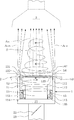
以下、本発明の実施形態について図を参照しながら説明する。図1は本発明に基づく焼成調理装置1の一例を表わす断面図、図2は本例の焼成調理装置1の拡大断面図、図3は本例の焼成調理装置1の平面図、図4はガイド枠14、焼き網121及び七輪12を取り除いた状態の図2相当拡大断面図であり、図5はガイド枠14、焼き網121及び七輪12を取り除いた状態の図3相当平面図である。本例の焼成調理装置1は、炭火焼き肉用で七輪12を用い、調理面として焼き網121を用いる構成である。図4及び図5は、他の部位との位置関係を明瞭にするため、七輪12を仮想線(二転鎖線)表示としている。
Hereinafter, embodiments of the present invention will be described with reference to the drawings. FIG. 1 is a sectional view showing an example of a
本発明の焼成調理装置1は、外観上は従来公知の同種装置と構成は変わらない。すなわち本例の焼成調理装置1は、図1〜図3に見られるように、テーブル2に設けたチャンバ11に七輪12を収納し、前記七輪12に載せる焼き網121で焼成する肉(調理物、図示略)から立ち上る煙を、焼き網121上方に配した排煙フード3へ導き、前記排煙フード3から外部へ排煙する。排煙フード3は、外部に通じる排気ファン(図示略)が接続されており、焼成調理装置1から上昇する旋回流Sを吸引し、前記旋回流Sが捕まえた煙を確実に排気する。排気ファンによる旋回流Sの吸引力は、旋回流Sの上昇力より強いことが好ましいため、排気ファンの能力は後述する給気ファンより高いことが望ましい。また、焼き網121から排煙フード3までの高さは自由であるが、上昇する旋回流Sを吸引でき、かつ利用者が邪魔に感じない高さとして、例えばテーブル2から排煙フード3までが450mm〜500mm程度が目安となる。この場合、本例の排気ファンの能力は、750m3/h〜850m3/hにする。
The configuration of the
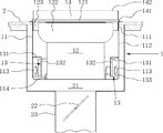
チャンバ11は、内径300mm、深さ200mmである平面視円形の金属製容器で、テーブル2をくり貫いて、チャンバ開口111から張り出す平面視方形の取付フランジ115によりテーブル2に固定し、テーブル2下方に突出する全体を空気供給外箱21により囲っている。チャンバ11は、テーブル2に対して着脱自在にしてもよい。空気供給外箱21は、内径340mm、深さ240mmのチャンバ11に相似な構造で、空気供給ダクト23を介して外部に通じる給気ファン(図示略)が接続されている。空気供給ダクト23は、内径150mmの金属製配管である。給気ファンは、外部から取り込んだ空気を、空気供給ダクト23から空気供給箱21へと送り込み、チャンバ壁面112に開口した吹込口113からチャンバ11内へ空気を吹き込ませる。空気の吹込み量は、空気供給ダクト23に設けた流量調整ダンパ22の開度により調節する。既述したように、給気ファンの能力は、相対的に排気ファンより低いことが好ましい。これから、排気ファンの能力を750m3/h〜850m3/hとした場合、給気ファンの能力は350m3/h〜450m3/hを目安とする。この場合、実際に吹込口113からチャンバ11内に吹き込む空気の量は、流量調整ダンパ22で調節できるため、給気ファンの能力は高めに設定するとよい。
The
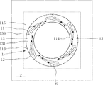
本例は、チャンバ壁面112の周方向に並ぶ18個の吹込口113と、一つおきの吹込口113を2個一組として被せた6個の吹出カバー13とから構成される(図4及び図5参照)。吹込口113は、30mm径の円形の開口で、中心がチャンバ11の底面から30mmの高さで周方向等間隔に設けている。吹出カバー13は、上面131、下面、側面132及び吹出口133からなる金属製の箱体で、チャンバ11に対しては溶接又はロウ付けする。本例の吹出カバー13は、吹出口133を周方向に向けて開口し、側面132をチャンバ壁面112から吹出口133に向けてチャンバ11の半径方向内向きに傾けている。また、発生させた旋回流Sに上向きの力を与えるため、上面131を吹出口133に向けた上り勾配にしている。前記勾配角は10度以下、数度程度でよい。これにより、各吹込口113からチャンバ11内に吹き込む空気は、吹出カバー13の側面132に衝突してチャンバ壁面112に沿った方向に変えられ、また上面131の上り勾配に沿って吹出口133からやや上向きに吹き出し、旋回しながら上昇する旋回流Sとなる。本例の吹出カバー13は、上面131が長辺100mm及び短辺28mmで直角を挟む略直角三角形、側面が高さ70mm、長さ100mmの長方形、そして吹出口133が高さ70mm、幅28mmの方形開口である。
This example is composed of 18
本例の調理面は前記七輪に載せる焼き網121である。本例の七輪12は、焼き網121がちょうどテーブルに面一な高さとなるように、チャンバ11の深さとほぼ同じ高さである。七輪12は、チャンバ11の底面に設けた七輪受け114に底部を嵌め込んで、前記底面に置く。七輪受け114は、旋回流Sの発生を妨げない高さ(例えば30mm)で、七輪12の底部より僅かに大きな内径(例えば210mm)の金属製環であり、中心がチャンバ11の中心に一致している。これにより、七輪受け114に底部を嵌め込んだ七輪12は、チャンバ11に中心を一致させ、半径方向外向きに膨出した上縁部122により、チャンバ壁面112と前記上縁部122下方との隙間より狭い環状の隙間123をチャンバ開口111に対して周方向に均等な幅で形成する。チャンバ11内に発生した旋回流Sは、前記隙間123を通じて焼き網121より上方へと上昇する。隙間123の大きさは、例えば七輪12の上部外径が260mmであれば、20mmである。
Tone Rimen of this example is a
ガイド枠14は、チャンバ壁面112に内接する大きさの金属製環であり、テーブル2から一定高さが突出するように、チャンバ開口111に引っかかる掛止凸条141を設けている。すなわち、ガイド枠14は、前記掛止凸条141より上方がテーブル2から突出し、同じく掛止凸条141より下方がチャンバ11に嵌め込まれる。本例のガイド枠14は、外径300mm(チャンバ11の内径にほぼ等しい)で、掛止凸条141から上方が35mm、同じく掛止凸条141より下方が30mmである。既述したように、焼き網121はテーブル2と面一になっているため、前記焼き網121はガイド枠開口142より下方位置に設けられることになる(本例で言えば、35mm下方)。このガイド枠14は、掛止凸条141によりチャンバ開口111に引っかかっているだけなので、着脱自在である(図4参照)。これにより、ガイド枠14を取り外した状態で、七輪12はチャンバ12に対して容易に出し入れできる。
The
本例の焼成調理装置1における旋回流Sの発生と、前記旋回流Sを竜巻状にして煙を排煙フード3へ導く働きとについて説明する。給気ファンにより外部から取り込まれた空気は、空気供給ダクト23を通じて空気供給外箱21へ送られる。チャンバ11は、吹込口113のみで前記空気供給箱体21と繋がっているから、空気供給外箱21へ送られた空気は前記吹込口113を通じてチャンバ11内に向けて吹き込む。ところが、吹込口113には吹出カバー13が被せられているので、前記空気は吹出カバー13の側面132に衝突し、吹出口133からチャンバ壁面112に沿って吹き出すことになる。このとき、吹出カバー13は上面131が吹出口133に向けて上り勾配となっているので、吹出口133から吹き出す空気は、上向きの力が僅かに与えられる。こうして、吹出カバー13の吹出口133から吹き出す空気は、旋回しながら上昇する旋回流Sを発生させる(図5参照)。
The generation of the swirl flow S in the
旋回流Sは、上述のように少し上向きに空気を吹き出すことによる上向きの力のほか、空気の吹出により高まるチャンバ11内の圧力と、上昇する空気Ainにより低くなる調理面121上の圧力との差により、チャンバ開口111に対して形成された隙間123を通じて上向きに吸引されて上昇していく。そして、焼き網121の高さに至ると、前記圧力差による吸引が半径方向内向きにも働き、旋回流Sは絞られながら上昇していくようになる。このとき、テーブル2に沿って焼き網121に向けて吹き込む空気Aoutは、ガイド枠14により遮られ、上向きに方向が変えられるため、調理面121より上方に上昇していく旋回流Sが撹乱させられる虞は少ない。また、本発明による旋回流Sは、旋回方向の力が強いため、焼き網121に向けて吹き込む空気Aoutによる影響を受けにくくなっており、そのまま旋回を続けて上昇していく。これは、焼き網121に向けて吹き込む空気Aoutが旋回流Sに混ざることなく、そのまま排煙フード3に向けて上昇していくことを意味する。
As described above, the swirling flow S includes an upward force generated by blowing air slightly upward as described above, a pressure in the
こうしてチャンバ11内に発生した旋回流Sは、焼き網121に向けて吹き込む空気Aoutに撹乱させられることなく、焼き網121上の上昇する空気Ainによる吸引、そして前記空気Ainの圧力と焼き網121に向けて吹き込む空気Aoutとの圧力差によって絞られ、自然と竜巻状になる(図1参照)。焼き網121上の肉から発生する煙は、旋回流Sの内側に発生するため、竜巻状となる旋回流Sより外に逃げ出すことはなく、また上述したように、焼き網121に向けて吹き込む空気Aoutが旋回流Sに混ざらず、そのまま上昇していくため、煙の拡散は前記焼き網121に向けて吹き込む空気Aoutに囲まれる旋回流Sの範囲に留められる。こうして、煙はすべて旋回流Sに捕まり、竜巻状の旋回流Sに従って、確実に排煙フード3へ導かれる。
Thus, the swirl flow S generated in the
1 焼成調理装置
11 チャンバ
111 チャンバ開口
112 チャンバ壁面
113 吹込口
12 七輪
121 焼き網
122 上縁部
123 隙間
13 吹出カバー
131 上面
132 側面
133 吹出口
14 ガイド枠
142 ガイド枠開口
2 テーブル
3 排煙フード
S 旋回流
Ain 上昇する空気
Aout 吹き込む空気
1 Baking cooker
11 chambers
111 Chamber opening
112 Chamber wall
113 Inlet
12 Seven wheels
121 grill
122 Upper edge
123 gap
13 Blowout cover
131 Top view
132 Side
133 Air outlet
14 Guide frame
142
Ain rising air
Aout blowing air
Claims (3)
チャンバは平面視円形で、前記チャンバに載置した七輪の上縁部により、チャンバ壁面と前記上縁部下方との隙間より狭い隙間をチャンバ開口に対して形成し、チャンバ壁面に沿って周方向に空気を吹き出す吹出口を七輪の上縁部より下方位置に設け、調理面はチャンバ開口より下方位置に設けてなり、
吹出口からチャンバ壁面に沿って空気を吹き出すことによりチャンバ内に旋回流を発生させ、空気の吹出により高まるチャンバ内と前記空気が上昇する七輪の調理面より上方との圧力差により、チャンバ開口に対して形成された隙間を通じて前記旋回流を上向きに吸引させて上昇させ、更に調理面上の上昇する空気と調理面に向けて吹き込む空気との圧力差により調理面を囲んで上昇する旋回流を竜巻状にして、調理面で焼成する調理物から立ち上がる煙を前記竜巻状の旋回流により捕まえて排煙フードへ導くことを特徴とする焼成調理装置。 A baking cooking apparatus capable of storing seven wheels in a chamber provided in a table and guiding smoke rising from a cooked product on the cooking surface of the seven wheels to a smoke hood,
The chamber has a circular shape in plan view, and the upper edge of the seven wheels placed in the chamber forms a gap narrower than the gap between the chamber wall surface and the lower portion of the upper edge with respect to the chamber opening, and the circumferential direction along the chamber wall surface to provide a blowout port for blowing out the air to the lower position than the upper edge of the charcoal brazier, tone Rimen will be provided at a lower position than the chamber opening,
A swirling flow is generated in the chamber by blowing air from the blowout outlet along the wall of the chamber, and the chamber opening is caused by the pressure difference between the inside of the chamber that is increased by blowing out the air and the upper cooking surface of the seven wheels where the air rises. It is raised by upward suction the swirling flow through a gap formed against further swirling flow increases surrounds the cooking surface by a pressure difference between the rising air above the cooking surface and the air blown toward the cooking surface A tornado-shaped baking cooking apparatus characterized in that smoke rising from a food to be baked on the cooking surface is captured by the tornado-shaped swirling flow and led to a smoke hood.
チャンバに載置した七輪の上縁部により、チャンバ壁面と前記上縁部下方との隙間より狭い隙間をチャンバ開口に対して形成し、前記七輪の調理面より下方位置に設けた吹出口から平面視円形のチャンバ壁面に沿って周方向に空気を吹き出してチャンバ内に旋回流を発生させ、空気の吹出により高まるチャンバ内と前記空気が上昇する七輪の調理面より上方との圧力差により、チャンバ開口に対して形成された隙間を通じて前記旋回流を上向きに吸引させて上昇させ、更に調理面上の上昇する空気と調理面に向けて吹き込む空気との圧力差により調理面を囲んで上昇する旋回流を竜巻状にして、調理面で焼成する調理物から立ち上がる煙を前記竜巻状の旋回流により捕まえて排煙フードへ導くことを特徴とする排煙方法。 A smoke exhausting method for guiding smoke rising from a cooked product to be baked on the cooking surface of the seven wheels of the baking cooking apparatus in which the seven wheels are stored in a chamber provided in a table,
The upper edge of the seven wheels placed in the chamber forms a gap narrower than the gap between the chamber wall surface and the lower portion of the upper edge with respect to the chamber opening, and is flat from the air outlet provided below the cooking surface of the seven wheels. Due to the pressure difference between the inside of the chamber that is increased by blowing air and the upper side of the cooking surface of the seven wheels where the air rises, the air is blown out in the circumferential direction along the wall surface of the circular chamber. opening is upwardly sucked the swirling flow through the gap formed with respect to rise, increasing surrounds the cooking surface by a pressure difference between the air blown toward the cooking surface and the air which rises on the further cooking surface A smoke exhausting method characterized in that a swirl flow is formed into a tornado shape, and smoke rising from a cooked product on the cooking surface is captured by the tornado-shaped swirl flow and guided to a smoke exhaust hood.
Priority Applications (1)
| Application Number | Priority Date | Filing Date | Title |
|---|---|---|---|
| JP2007100006A JP4728998B2 (en) | 2007-04-06 | 2007-04-06 | Baking cooking apparatus and smoke exhausting method used therefor |
Applications Claiming Priority (1)
| Application Number | Priority Date | Filing Date | Title |
|---|---|---|---|
| JP2007100006A JP4728998B2 (en) | 2007-04-06 | 2007-04-06 | Baking cooking apparatus and smoke exhausting method used therefor |
Publications (3)
| Publication Number | Publication Date |
|---|---|
| JP2008256292A JP2008256292A (en) | 2008-10-23 |
| JP2008256292A5 JP2008256292A5 (en) | 2010-05-06 |
| JP4728998B2 true JP4728998B2 (en) | 2011-07-20 |
Family
ID=39980024
Family Applications (1)
| Application Number | Title | Priority Date | Filing Date |
|---|---|---|---|
| JP2007100006A Expired - Fee Related JP4728998B2 (en) | 2007-04-06 | 2007-04-06 | Baking cooking apparatus and smoke exhausting method used therefor |
Country Status (1)
| Country | Link |
|---|---|
| JP (1) | JP4728998B2 (en) |
Cited By (1)
| Publication number | Priority date | Publication date | Assignee | Title |
|---|---|---|---|---|
| KR101967852B1 (en) * | 2018-06-18 | 2019-04-10 | 김재동 | Grilled table with air curtains |
Families Citing this family (7)
| Publication number | Priority date | Publication date | Assignee | Title |
|---|---|---|---|---|
| BRPI0823212B1 (en) | 2008-09-23 | 2021-03-30 | Koninklijke Philips N.V. | FOOD PREPARATION APPARATUS AND AIR GUIDE MEMBER FOR THE SAME |
| KR101126983B1 (en) | 2010-03-12 | 2012-03-29 | 주식회사 골드푸드시스템 | Apparatus for Barbecue |
| CN109716037A (en) | 2016-06-22 | 2019-05-03 | 国立大学法人名古屋工业大学 | Suction device and driving device |
| CN107816742B (en) * | 2017-11-27 | 2023-01-03 | 佛山市云米电器科技有限公司 | Non-planar smoke ventilator based on venturi effect |
| CN107796033B (en) * | 2017-11-27 | 2022-12-30 | 佛山市云米电器科技有限公司 | Range hood capable of preventing fan from being polluted inside |
| CN110394345A (en) * | 2018-04-24 | 2019-11-01 | 惠州比亚迪电子有限公司 | Whirlwind blowing and drawing type exhaust system |
| CN109373373A (en) * | 2018-09-20 | 2019-02-22 | 常州大学 | A kind of household cooker hood |
Citations (2)
| Publication number | Priority date | Publication date | Assignee | Title |
|---|---|---|---|---|
| JPS63297952A (en) * | 1987-05-29 | 1988-12-05 | Japan Steel Works Ltd:The | Method and device for discharging smoke in kitchen range |
| JPH1144444A (en) * | 1997-07-25 | 1999-02-16 | Ahresty Corp | Indoor smoke and air discharging device |
Family Cites Families (2)
| Publication number | Priority date | Publication date | Assignee | Title |
|---|---|---|---|---|
| JPS63131931A (en) * | 1986-11-21 | 1988-06-03 | Matsushita Electric Works Ltd | Smoke disposal device for cooking |
| JP2938256B2 (en) * | 1991-12-09 | 1999-08-23 | 高砂熱学工業株式会社 | Exhaust device |
-
2007
- 2007-04-06 JP JP2007100006A patent/JP4728998B2/en not_active Expired - Fee Related
Patent Citations (2)
| Publication number | Priority date | Publication date | Assignee | Title |
|---|---|---|---|---|
| JPS63297952A (en) * | 1987-05-29 | 1988-12-05 | Japan Steel Works Ltd:The | Method and device for discharging smoke in kitchen range |
| JPH1144444A (en) * | 1997-07-25 | 1999-02-16 | Ahresty Corp | Indoor smoke and air discharging device |
Cited By (1)
| Publication number | Priority date | Publication date | Assignee | Title |
|---|---|---|---|---|
| KR101967852B1 (en) * | 2018-06-18 | 2019-04-10 | 김재동 | Grilled table with air curtains |
Also Published As
| Publication number | Publication date |
|---|---|
| JP2008256292A (en) | 2008-10-23 |
Similar Documents
| Publication | Publication Date | Title |
|---|---|---|
| JP4728998B2 (en) | Baking cooking apparatus and smoke exhausting method used therefor | |
| JP5452503B2 (en) | Exhaust booster | |
| KR20080024948A (en) | Grill configuration having a forced air curtain and its associated method of operation | |
| JPH03137444A (en) | Rear shelf-compensation-type exhaust hood device | |
| JP2003207184A (en) | Air-supply outlet structure of supply and exhaust type kitchen ventilator | |
| CN111503695A (en) | Air inlet structure and combined cooking equipment | |
| ES2950565T3 (en) | Extractor hood with forced air injection | |
| JP2002089859A (en) | Roaster | |
| WO2006001065A1 (en) | Range hood forming air curtain by indoor air | |
| JPH0418215B2 (en) | ||
| KR100865430B1 (en) | Grill Assembly and Using Method Thereof | |
| JP3085249B2 (en) | Hot plate | |
| KR102176927B1 (en) | Charcoal brazier | |
| CN209459012U (en) | A kind of wind-curtain type household smoke exhaust ventilator | |
| JP4656866B2 (en) | Range food | |
| CN208547015U (en) | Kitchen ventilator | |
| CN220554467U (en) | Vortex desk type barbecue oven | |
| JP3142375U (en) | Wood-burning stove | |
| CN205747052U (en) | A kind of structure improved smoke exhaust | |
| JP2000161738A (en) | Exhauster for cooking | |
| JP2003194345A5 (en) | ||
| JP3485201B2 (en) | Range hood fan | |
| JP6423479B2 (en) | Electric heater for cooking | |
| JP3437531B2 (en) | Cooking device | |
| KR200412455Y1 (en) | Air curtain formation device for food roaster |
Legal Events
| Date | Code | Title | Description |
|---|---|---|---|
| A521 | Request for written amendment filed |
Free format text: JAPANESE INTERMEDIATE CODE: A523 Effective date: 20100323 |
|
| A621 | Written request for application examination |
Free format text: JAPANESE INTERMEDIATE CODE: A621 Effective date: 20100323 |
|
| A871 | Explanation of circumstances concerning accelerated examination |
Free format text: JAPANESE INTERMEDIATE CODE: A871 Effective date: 20100323 |
|
| A975 | Report on accelerated examination |
Free format text: JAPANESE INTERMEDIATE CODE: A971005 Effective date: 20100407 |
|
| A977 | Report on retrieval |
Free format text: JAPANESE INTERMEDIATE CODE: A971007 Effective date: 20100707 |
|
| A131 | Notification of reasons for refusal |
Free format text: JAPANESE INTERMEDIATE CODE: A131 Effective date: 20100713 |
|
| A521 | Request for written amendment filed |
Free format text: JAPANESE INTERMEDIATE CODE: A523 Effective date: 20100909 |
|
| A02 | Decision of refusal |
Free format text: JAPANESE INTERMEDIATE CODE: A02 Effective date: 20101005 |
|
| A521 | Request for written amendment filed |
Free format text: JAPANESE INTERMEDIATE CODE: A523 Effective date: 20110105 |
|
| A521 | Request for written amendment filed |
Free format text: JAPANESE INTERMEDIATE CODE: A821 Effective date: 20110107 |
|
| A911 | Transfer to examiner for re-examination before appeal (zenchi) |
Free format text: JAPANESE INTERMEDIATE CODE: A911 Effective date: 20110210 |
|
| TRDD | Decision of grant or rejection written | ||
| A01 | Written decision to grant a patent or to grant a registration (utility model) |
Free format text: JAPANESE INTERMEDIATE CODE: A01 Effective date: 20110412 |
|
| A01 | Written decision to grant a patent or to grant a registration (utility model) |
Free format text: JAPANESE INTERMEDIATE CODE: A01 |
|
| A61 | First payment of annual fees (during grant procedure) |
Free format text: JAPANESE INTERMEDIATE CODE: A61 Effective date: 20110415 |
|
| R150 | Certificate of patent or registration of utility model |
Ref document number: 4728998 Country of ref document: JP Free format text: JAPANESE INTERMEDIATE CODE: R150 Free format text: JAPANESE INTERMEDIATE CODE: R150 |
|
| FPAY | Renewal fee payment (event date is renewal date of database) |
Free format text: PAYMENT UNTIL: 20140422 Year of fee payment: 3 |
|
| R250 | Receipt of annual fees |
Free format text: JAPANESE INTERMEDIATE CODE: R250 |
|
| R250 | Receipt of annual fees |
Free format text: JAPANESE INTERMEDIATE CODE: R250 |
|
| R250 | Receipt of annual fees |
Free format text: JAPANESE INTERMEDIATE CODE: R250 |
|
| R250 | Receipt of annual fees |
Free format text: JAPANESE INTERMEDIATE CODE: R250 |
|
| R250 | Receipt of annual fees |
Free format text: JAPANESE INTERMEDIATE CODE: R250 |
|
| R250 | Receipt of annual fees |
Free format text: JAPANESE INTERMEDIATE CODE: R250 |
|
| R250 | Receipt of annual fees |
Free format text: JAPANESE INTERMEDIATE CODE: R250 |
|
| R250 | Receipt of annual fees |
Free format text: JAPANESE INTERMEDIATE CODE: R250 |
|
| R250 | Receipt of annual fees |
Free format text: JAPANESE INTERMEDIATE CODE: R250 |
|
| LAPS | Cancellation because of no payment of annual fees |