JP4726185B2 - Eccentric oscillating gear unit - Google Patents
Eccentric oscillating gear unit Download PDFInfo
- Publication number
- JP4726185B2 JP4726185B2 JP2004327633A JP2004327633A JP4726185B2 JP 4726185 B2 JP4726185 B2 JP 4726185B2 JP 2004327633 A JP2004327633 A JP 2004327633A JP 2004327633 A JP2004327633 A JP 2004327633A JP 4726185 B2 JP4726185 B2 JP 4726185B2
- Authority
- JP
- Japan
- Prior art keywords
- pin
- gear
- eccentric oscillating
- carrier
- internal
- Prior art date
- Legal status (The legal status is an assumption and is not a legal conclusion. Google has not performed a legal analysis and makes no representation as to the accuracy of the status listed.)
- Active
Links
- 238000005096 rolling process Methods 0.000 claims description 9
- 230000001105 regulatory effect Effects 0.000 claims description 3
- 238000012986 modification Methods 0.000 description 3
- 230000004048 modification Effects 0.000 description 3
- 239000003638 chemical reducing agent Substances 0.000 description 2
- 230000002093 peripheral effect Effects 0.000 description 2
- 230000005540 biological transmission Effects 0.000 description 1
- 230000000694 effects Effects 0.000 description 1
- 230000020169 heat generation Effects 0.000 description 1
- 230000000452 restraining effect Effects 0.000 description 1
Images


Classifications
-
- F—MECHANICAL ENGINEERING; LIGHTING; HEATING; WEAPONS; BLASTING
- F16—ENGINEERING ELEMENTS AND UNITS; GENERAL MEASURES FOR PRODUCING AND MAINTAINING EFFECTIVE FUNCTIONING OF MACHINES OR INSTALLATIONS; THERMAL INSULATION IN GENERAL
- F16H—GEARING
- F16H1/00—Toothed gearings for conveying rotary motion
- F16H1/28—Toothed gearings for conveying rotary motion with gears having orbital motion
- F16H1/32—Toothed gearings for conveying rotary motion with gears having orbital motion in which the central axis of the gearing lies inside the periphery of an orbital gear
-
- F—MECHANICAL ENGINEERING; LIGHTING; HEATING; WEAPONS; BLASTING
- F16—ENGINEERING ELEMENTS AND UNITS; GENERAL MEASURES FOR PRODUCING AND MAINTAINING EFFECTIVE FUNCTIONING OF MACHINES OR INSTALLATIONS; THERMAL INSULATION IN GENERAL
- F16H—GEARING
- F16H1/00—Toothed gearings for conveying rotary motion
Landscapes
- Engineering & Computer Science (AREA)
- General Engineering & Computer Science (AREA)
- Mechanical Engineering (AREA)
- Retarders (AREA)
- Rolling Contact Bearings (AREA)
Description
本発明は、外歯がトロコイド歯形であり、内歯がピン歯車である偏心揺動型歯車装置に関するものである。 The present invention relates to an eccentric oscillating gear device in which outer teeth are trochoidal teeth and inner teeth are pin gears.
偏心揺動型歯車装置は、例えば産業用ロボットの関節部に設けられてロボットのアーム部材を駆動する減速機等に用いられている。下記特許文献1には、外歯がペリトロコイド歯形からなり、内歯がピン歯車からなる偏心揺動型歯車装置が開示されている。この偏心揺動型歯車装置は、図4(a)、(b)のように、外歯51の歯先51aの先端部を切除することで、ピン52を挿入する円形溝が形成された内歯部材本体の内径部との接触を避けるようにしたり、内歯53のトルク伝達に寄与しない側のピン52が強制的に自転させられる時間が減少し、内部発熱を低減して焼付による故障を解消するようにしている。
The eccentric oscillating gear device is used, for example, in a speed reducer that is provided at a joint portion of an industrial robot and drives an arm member of the robot. Patent Document 1 below discloses an eccentric oscillating gear device in which outer teeth are made of a peritrochoidal tooth profile and inner teeth are made of a pin gear. As shown in FIGS. 4 (a) and 4 (b), this eccentric oscillating gear device has a circular groove into which a
上述のように外歯51の歯先51aの先端部を切除した場合、図4(a)の下方部分及び図4(b)に示すように、偏心方向の180°対向位置でピン52が遊んでしまうため、ピン52が傾いたりピン溝52aから脱落し易くなってしまう。かかる事態が発生すると、ペリトロコイド歯形の外歯51がピン52を噛み込んでしまい異音が発生したり、ピン溝52aが変形したりする。また、歯車装置の出力がロックしてしまうこともある。
When the tip portion of the
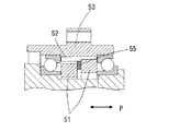
以上のような問題を解消するために、図5、図6に示すように、ピン52を拘束(ピンの傾きを押さえる)するために、ピン押えリング55を外歯51と51との間に配置したり(図5)、または、ピン押えリング56を外歯51と軸受58との間に配置し、もう1つのピン押えリング57を外歯51と軸受59との間に配置する(図6)必要があった(例えば、下記特許文献2参照)。
In order to solve the above problems, as shown in FIGS. 5 and 6, in order to restrain the pin 52 (to suppress the inclination of the pin), the
しかし、図5,図6のピン押えリング55〜57のようなピン押え部材を使用すると、部品点数が増加するとともに、装置が軸方向Pに大きくなり設計自由度が損なわれていた。
本発明は、上述のような従来技術の問題に鑑み、外歯歯車の歯先部を切除した構造を採用した場合にピン押え部材を省略でき設計自由度を向上できるようにした偏心揺動型歯車装置を提供することを目的とする。 In view of the problems of the prior art as described above, the present invention provides an eccentric oscillating type in which a pin pressing member can be omitted and the degree of freedom of design can be improved when a structure in which a tooth tip portion of an external gear is cut is adopted. An object is to provide a gear device.
上記目的を達成するために、本発明による偏心揺動型歯車装置は、内周に内歯ピンを有する内歯歯車と、前記内歯歯車に対して相対的に回転できるキャリアと、転動体とその転動体を支持する輪体とを有し前記キャリアの外周と前記内歯歯車の内周との間に配設された一対の軸受と、前記キャリアに回転自在に支持されたクランク軸と、歯先部が切除されたトロコイド歯形の外歯を外周に有して前記内歯ピンに前記外周が噛み合うとともに前記クランク軸のクランク部分に係合しかつ前記一対の軸受間に配設された外歯歯車と、を備え、前記クランク軸の回転によって前記外歯歯車が偏心揺動運動して前記内歯歯車又は前記キャリアから回転出力を取り出すように構成した偏心揺動型歯車装置において、前記一対の軸受の前記外歯歯車側の端面に前記内歯ピンの端部を受ける受け部と前記内歯ピンと平行に突き出た突き出し部とを形成し、前記受け部が前記突き出し部により溝状に形成され、前記内歯ピンを前記受け部で支持することにより前記内歯ピンの前記キャリア側への移動を規制することを特徴とする。 In order to achieve the above object, an eccentric oscillating gear device according to the present invention includes an internal gear having an internal pin on the inner periphery, a carrier that can rotate relative to the internal gear, a rolling element, A pair of bearings provided between the outer periphery of the carrier and the inner periphery of the internal gear, and a crankshaft rotatably supported by the carrier; A trochoidal tooth shape with outer teeth cut off on the outer periphery, the outer periphery meshes with the inner tooth pin, engages with the crank portion of the crankshaft, and is disposed between the pair of bearings. An eccentric oscillating gear device configured to extract the rotational output from the internal gear or the carrier by the eccentric oscillating movement of the crankshaft by the rotation of the crankshaft. End of the external gear on the side of the external gear The inner and the receiving portion for receiving an end portion of the gear pins are formed and said inner teeth pins parallel to protruding protrusion, the receiving portion is formed into a groove shape by the projecting portion, the said inner gear pins receiving portion The movement to the carrier side of the internal tooth pin is regulated by supporting the pin .
この偏心揺動型歯車装置によれば、一対の軸受の外歯歯車側の端面に形成した溝状の受け部で内歯ピンを受けて支持することにより、外歯歯車の歯先部が切除された構造を採用した場合に、外歯歯車に対し遊ぶ状態にある内歯ピンのキャリア側への移動を規制するので、従来のようなピン押え部材を省略でき、設計自由度を向上できるとともに、装置をピン押え部材の分だけ軸方向に短くすることができる。また、受け部は、軸受にピン押え機能を付加したので、専用の部品を使用する必要がなく、部品点数を少なくでき、コストメリットを得ることができる。 According to the eccentric oscillating gear device, the tooth tip portion of the external gear is cut off by receiving and supporting the internal tooth pin by the groove-shaped receiving portion formed on the end surface of the pair of bearings on the external gear side. When the adopted structure is adopted, the movement of the internal tooth pin in a play state with respect to the external gear to the carrier side is restricted, so that the conventional pin holding member can be omitted and the degree of freedom in design can be improved. The device can be shortened in the axial direction by the amount of the pin pressing member. In addition, since the receiving portion has a pin holding function added to the bearing, it is not necessary to use a dedicated component, the number of components can be reduced, and cost merit can be obtained.
上記偏心揺動型歯車装置において前記一対の軸受の輪体は外輪と内輪を備え、前記受け部および前記突き出し部を前記外輪または前記内輪に形成するように構成できる。また、前記一対の軸受の前記外歯歯車側の端面で前記外歯歯車の軸方向への移動を規制するように構成できる。 In the eccentric oscillating gear device, the ring body of the pair of bearings may include an outer ring and an inner ring, and the receiving part and the protruding part may be formed on the outer ring or the inner ring. Moreover, it can comprise so that the movement to the axial direction of the said external gear may be regulated by the end surface by the side of the said external gear of a pair of said bearing.
本発明の偏心揺動型歯車装置によれば、外歯歯車の歯先部を切除した構造を採用した場合に従来のようなピン押え部材を省略できるので、部品点数を削減でき、設計自由度を向上できる。 According to the eccentric oscillating gear device of the present invention, when a structure in which the tooth tip portion of the external gear is cut off is adopted, the conventional pin pressing member can be omitted, so the number of parts can be reduced and the degree of freedom in design can be reduced. Can be improved.
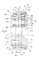
以下、本発明を実施するための最良の形態について図面を用いて説明する。図1は本発明の実施の形態による偏心揺動型歯車装置の側断面図である。図2は図1の要部側断面図である。図3は図2の主軸受の外輪側面に設けた受け部とピンとの相対位置関係を示す部分正面図である。 The best mode for carrying out the present invention will be described below with reference to the drawings. FIG. 1 is a side sectional view of an eccentric oscillating gear device according to an embodiment of the present invention. FIG. 2 is a sectional side view of the main part of FIG. FIG. 3 is a partial front view showing a relative positional relationship between the receiving portion provided on the outer ring side surface of the main bearing of FIG. 2 and the pin.
図1に示す偏心揺動型歯車装置10は、内周部に形成された複数のピン溝(図4参照)と各ピン溝に配置された複数のピン(内歯)15aとを有する内歯歯車15と、内歯歯車15に対して相対的に回転可能なキャリア11と、キャリア11の外周と内歯歯車15の内周との間に配設されたラジアル玉軸受からなる一対の主軸受19,20と、キャリア11に回転自在に支持された複数のクランク軸16と、歯先部が切除されたトロコイド系のペリトロコイド歯形の外歯(図4参照)を外周に有して各ピン15aに外周が噛み合うとともにクランク軸16のクランク部分16c、16dに係合しかつ一対の主軸受19,20間に配設された外歯歯車13,14と、を備える。
An eccentric
外歯歯車13,14は、複数のクランク軸16のクランク部分16c、16dにより、コロ軸受13a,14aを介して内歯歯車15の中心軸線に対し偏心して公転運動可能に支持されている。
The
キャリア11は、ブロック11aと、外歯歯車13,14に形成された複数の円形孔9内に位置する複数の柱部11bと、複数の柱部11bに複数のボルト11dで固定された端円板11cと、を備える。
The
キャリア11は、内歯歯車15に対し主軸受19,20を介して回転自在に結合され、クランク軸16の両端部を円すいコロ軸受16a、16bを介してブロック11a及び端円板11cで回転自在に支持する。なお、円すいコロ軸受16aは止めリング16eでブロック11aに取り付け固定され、円すいコロ軸受16bは止めリング16fで端円板11cに取り付け固定されている。
The
複数のクランク軸16の1つには、その軸端部16gに入力歯車17が止めリング16hにより固定されて装着されている。キャリア11及び外歯歯車13,14の略中心に貫通して形成された中空孔12を通して入力歯車17の外歯17aに噛み合う歯車を有する入力軸(図示省略)が配置される。
One of the plurality of
クランク軸16が入力歯車17等を介して外部のモータ等からの回転力が伝達されて回転することにより、入力歯車17の外歯17aに噛み合う入力軸(図9参照)を介して外部のモータ等からの回転力が伝達されて回転することにより、外歯歯車13,14が公転運動しながら、外歯歯車13,14の歯数より例えば1つ歯数が多い内歯歯車15のピン15aに噛合う。クランク軸16の回転によって、公転1回につき歯数差(1)に対応して外歯歯車13,14が自転しながら偏心揺動運動することで、図1の偏心揺動型歯車装置10は外側ケースとしての内歯歯車15またはキャリア11からその自転に対応して減速回転出力を取り出すことのできる減速機として動作するようになっている。
When the
主軸受19は、球状の転動体19aと、転動体19aを支持する外輪19bと内輪19cとから構成される輪体と、を有する。同様に、主軸受20は、球状の転動体20aと、転動体20aを支持する外輪20bと内輪20cとから構成される輪体と、を有する。
The main bearing 19 includes a spherical
主軸受20は端円板11cの段部に内輪20cが外歯歯車14の側面に接するように位置しブッシュ20dにより押さえられ、また、主軸受19はブロック11aの段部に内輪19cが外歯歯車13の側面に接するように位置している。
The
また、主軸受19近傍の内歯歯車15とブロック11aとの間にオイルシール15cが配置されている。内歯歯車15は、外側ケースを構成し、孔15bでボルトにより例えばロボットのアーム等に取り付けられる。
An
次に、主軸受19,20の各端面に受け部を設けてピン15aを拘束する構成について図2、図3を参照して説明する。
Next, the structure which provides a receiving part in each end surface of the
図2のように、主軸受19,20の外輪19b、20bには、外歯歯車13,14側の各端面においてピン溝(図4)内のピン15aを保持するようにピン15aとほぼ平行に若干突き出た突き出し部22が設けられており、図3のように、突き出し部22により溝状に受け部21が形成されている。各ピン15aは、ピン15aの両端23で受け部21内に位置し支持されている。
As shown in FIG. 2, the
外歯歯車13,14の歯先部が切除された構造を採用した場合に、図2、図3の受け部21で各ピン15aを両端23で受けて支持するので、図4(a)、(b)のように外歯歯車13,14に対しピン15aが遊ぶ状態にあっても、かかるピン15aのキャリア11側への移動を規制できる。
When the structure in which the tooth tips of the
従って、本実施の形態による偏心揺動型歯車装置10によれば、従来の図5,図6ようなピン押え部材55〜57が必要ないので、装置の設計自由度が向上するとともに、装置を軸方向Pに短く構成できる。主軸受19,20にピン押え機能を付加したので、専用の部品を使用する必要がなく部品点数を削減でき、コストメリットも得ることができる。
Therefore, according to the eccentric oscillating
次に、本発明による別の実施の形態の偏心揺動型歯車装置について図9,図10を参照して説明する。図9は別の実施の形態による偏心揺動型歯車装置の側断面図である。図10は図9の要部側断面図である。 Next, an eccentric oscillating gear device according to another embodiment of the present invention will be described with reference to FIGS. FIG. 9 is a side sectional view of an eccentric oscillating gear device according to another embodiment. FIG. 10 is a sectional side view of the main part of FIG.
図9の偏心揺動型歯車装置10’は、図1の構成と基本的に同じ構成であり、ピンを拘束する受け部を主軸受の内輪に形成した点が異なり、同一部分には同じ符号を付けてその説明を省略する。
The eccentric
図9のように、内歯歯車15は、内周部が図1よりも装置10’の中心側に突き出ており、複数のピン溝内に位置する複数のピン15aは、主軸受19,20の外輪19b、20bを越えて内輪19c、20cの近傍に位置している。このため、図9,図10のように、内輪19c、20cには、外歯歯車13,14側の各端面においてピン溝(図4)内のピン15aを保持するようにピン15aとほぼ平行に若干突き出た突き出し部22が設けられており、突き出し部22により溝状に受け部21が形成されている。各ピン15aは、ピン15aの両端23で受け部21内に位置し支持されている。
As shown in FIG. 9, the
上述のように、図9,図10では、外歯歯車13,14の歯先部が切除された構造を採用した場合に、受け部21で各ピン15aを両端23で受けて支持するので、図4(a)、(b)のように外歯歯車13,14に対しピン15aが遊ぶ状態にあっても、かかるピン15aのキャリア11側への移動を規制できる。
As described above, in FIGS. 9 and 10, when the structure in which the tooth tip portions of the
また、図9,図10では、主軸受19,20の内輪19c、20cの突き出し部22の端面で外歯歯車13,14の軸方向の移動を規制している。
9 and 10, the axial movement of the
なお、中空孔12に入力軸12aが配置されており、入力軸12aの歯車が入力歯車17の外歯17aに噛み合い、入力軸12aの回転により入力歯車17が回転する。
The
図9,図10の偏心揺動型歯車装置10’によれば、図1,図2と同様に、従来の図5,図6ようなピン押え部材55〜57が必要ないので、装置の設計自由度が向上するとともに、装置を軸方向Pに短く構成できる。主軸受19,20にピン押え機能を付加したので、専用の部品を使用する必要がなく部品点数を削減でき、コストメリットも得ることができる。
According to the eccentric
以上のように本発明を実施するための最良の形態について説明したが、本発明はこれらに限定されるものではなく、本発明の技術的思想の範囲内で各種の変形が可能である。例えば、図1,図2では、主軸受19,20の内輪19c、20cで、外歯歯車13,14が軸方向に移動するのを規制しているが、外輪の突き出し部22の端面で外歯歯車13,14の軸方向の移動を規制しても良い。例えば、図11のように、主軸受19,20の外輪19b、20bの突き出し部22でピン15aを受ける受け部21を構成するとともに突き出し部22の端面が外歯歯車13,14の側面で外歯歯車13,14が軸方向に移動するのを規制する。図11では、内輪19c、20cは外歯歯車13,14の側面から離れており、外歯歯車13,14の軸方向の移動規制に関与していない。
As described above, the best mode for carrying out the present invention has been described. However, the present invention is not limited to these, and various modifications are possible within the scope of the technical idea of the present invention. For example, in FIGS. 1 and 2, the
また、主軸受19,20の各端面に設ける受け部は図7,図8のように構成してもよい。即ち、図7のように、主軸受19,20の外輪19b、20bの各端面においてピン溝(図4)内のピン15aを保持するようにピン15aとほぼ平行に若干突き出た一対の突き出し部22、24が設けられており、図8のように、突き出し部22と24との間に溝状に受け部25が形成されている。各ピン15aは、ピン15aの両端23で受け部25内に位置し支持されている。受け部25で各ピン15aを両端23で受けて支持するので、外歯歯車13,14に対しピン15aが遊ぶ状態にあっても、かかるピン15aのキャリア11側への移動を規制でき、図2,図3と同様の効果を得ることができる。
Moreover, you may comprise the receiving part provided in each end surface of the
また、図2,図7では、受け部21,25を主軸受19,20の外輪19b、20bの端面に形成したが、同様の受け部を内輪19c、20cに形成するように構成してもよい(図9,図10参照)。
2 and 7, the receiving
10 偏心揺動型歯車装置
10’ 偏心揺動型歯車装置
11 キャリア
13,14 外歯歯車
15 内歯歯車
15a ピン、内歯ピン
16 クランク軸
16c、16d クランク部分
19 主軸受
19a 転動体
19b 外輪
19c 内輪
20 主軸受
20a 転動体
20b 外輪
20c 内輪
21 受け部
23 ピンの両端(端部)
25 受け部
52a ピン溝
P 軸方向
DESCRIPTION OF
25 Receiving
Claims (3)
前記内歯歯車に対して相対的に回転できるキャリアと、
転動体とその転動体を支持する輪体とを有し前記キャリアの外周と前記内歯歯車の内周との間に配設された一対の軸受と、
前記キャリアに回転自在に支持されたクランク軸と、
歯先部が切除されたトロコイド歯形の外歯を外周に有して前記内歯ピンに前記外周が噛み合うとともに前記クランク軸のクランク部分に係合しかつ前記一対の軸受間に配設された外歯歯車と、を備え、前記クランク軸の回転によって前記外歯歯車が偏心揺動運動して前記内歯歯車又は前記キャリアから回転出力を取り出すように構成した偏心揺動型歯車装置において、
前記一対の軸受の前記外歯歯車側の端面に前記内歯ピンの端部を受ける受け部と前記内歯ピンと平行に突き出た突き出し部とを形成し、前記受け部が前記突き出し部により溝状に形成され、前記内歯ピンを前記受け部で支持することにより前記内歯ピンの前記キャリア側への移動を規制することを特徴とする偏心揺動型歯車装置。 An internal gear having an internal tooth pin on the inner circumference;
A carrier capable of rotating relative to the internal gear;
A pair of bearings having a rolling element and a ring that supports the rolling element and disposed between an outer periphery of the carrier and an inner periphery of the internal gear;
A crankshaft rotatably supported by the carrier;
A trochoidal tooth shape with outer teeth cut off on the outer periphery, the outer periphery meshes with the inner tooth pin, engages with the crank portion of the crankshaft, and is disposed between the pair of bearings. An eccentric oscillating gear device configured to extract the rotational output from the internal gear or the carrier by eccentric oscillating movement by rotation of the crankshaft,
A receiving portion that receives the end portion of the internal tooth pin and a protruding portion that protrudes in parallel with the internal tooth pin are formed on the end surfaces of the pair of bearings on the external gear side, and the receiving portion is formed in a groove shape by the protruding portion. The eccentric oscillating gear device is characterized in that movement of the internal tooth pin toward the carrier side is regulated by supporting the internal tooth pin by the receiving portion .
Priority Applications (7)
| Application Number | Priority Date | Filing Date | Title |
|---|---|---|---|
| JP2004327633A JP4726185B2 (en) | 2004-01-13 | 2004-11-11 | Eccentric oscillating gear unit |
| PCT/JP2004/019121 WO2005073595A1 (en) | 2004-01-13 | 2004-12-21 | Eccentrically swinging gear device |
| EP04807478A EP1707845B1 (en) | 2004-01-13 | 2004-12-21 | Eccentrically swinging gear device |
| US10/597,121 US7604559B2 (en) | 2004-01-13 | 2004-12-21 | Eccentrically oscillating gear device |
| CN2004800402964A CN1902415B (en) | 2004-01-13 | 2004-12-21 | Eccentrically swinging gear device |
| KR1020067014076A KR101100920B1 (en) | 2004-01-13 | 2004-12-21 | Eccentrically Swinging Gear Device |
| TW094100642A TW200532124A (en) | 2004-01-13 | 2005-01-10 | Eccentrically swinging gear device |
Applications Claiming Priority (3)
| Application Number | Priority Date | Filing Date | Title |
|---|---|---|---|
| JP2004005237 | 2004-01-13 | ||
| JP2004005237 | 2004-01-13 | ||
| JP2004327633A JP4726185B2 (en) | 2004-01-13 | 2004-11-11 | Eccentric oscillating gear unit |
Publications (3)
| Publication Number | Publication Date |
|---|---|
| JP2005226827A JP2005226827A (en) | 2005-08-25 |
| JP2005226827A5 JP2005226827A5 (en) | 2010-07-22 |
| JP4726185B2 true JP4726185B2 (en) | 2011-07-20 |
Family
ID=34829396
Family Applications (1)
| Application Number | Title | Priority Date | Filing Date |
|---|---|---|---|
| JP2004327633A Active JP4726185B2 (en) | 2004-01-13 | 2004-11-11 | Eccentric oscillating gear unit |
Country Status (7)
| Country | Link |
|---|---|
| US (1) | US7604559B2 (en) |
| EP (1) | EP1707845B1 (en) |
| JP (1) | JP4726185B2 (en) |
| KR (1) | KR101100920B1 (en) |
| CN (1) | CN1902415B (en) |
| TW (1) | TW200532124A (en) |
| WO (1) | WO2005073595A1 (en) |
Families Citing this family (34)
| Publication number | Priority date | Publication date | Assignee | Title |
|---|---|---|---|---|
| US8033942B2 (en) * | 2002-11-25 | 2011-10-11 | Delbert Tesar | Manufacture and use of parallel eccentric electro-mechanical actuator |
| US9879760B2 (en) * | 2002-11-25 | 2018-01-30 | Delbert Tesar | Rotary actuator with shortest force path configuration |
| JP5122450B2 (en) * | 2006-06-13 | 2013-01-16 | ナブテスコ株式会社 | Reduction gear |
| JP5197142B2 (en) * | 2008-05-12 | 2013-05-15 | 住友重機械工業株式会社 | Seal structure |
| JP5121696B2 (en) * | 2008-12-29 | 2013-01-16 | 住友重機械工業株式会社 | Reduction gear |
| JP5270462B2 (en) * | 2009-06-15 | 2013-08-21 | ナブテスコ株式会社 | Eccentric oscillating gear device and crankshaft assembling method in eccentric oscillating gear device |
| JP2012132523A (en) * | 2010-12-22 | 2012-07-12 | Nabtesco Corp | Gear transmission |
| MX2013012159A (en) * | 2011-04-21 | 2014-06-23 | Infusion Brands Inc | Dual oscillating multi-tool saw. |
| JP5782321B2 (en) * | 2011-07-15 | 2015-09-24 | ナブテスコ株式会社 | Gear device |
| JP5779120B2 (en) * | 2012-02-24 | 2015-09-16 | 住友重機械工業株式会社 | Eccentric oscillation type speed reducer |
| JP5466739B2 (en) * | 2012-08-24 | 2014-04-09 | ナブテスコ株式会社 | Eccentric oscillating gear unit |
| US8663049B1 (en) * | 2012-11-28 | 2014-03-04 | Tsun-Tien Yao | Speed reducer |
| US9862263B2 (en) | 2013-03-01 | 2018-01-09 | Delbert Tesar | Multi-speed hub drive wheels |
| CN104100680B (en) * | 2013-04-12 | 2017-07-21 | 鸿富锦精密工业(深圳)有限公司 | Cycloidal planetary gear speed reducer structure |
| JP6584054B2 (en) * | 2014-03-28 | 2019-10-02 | 住友重機械工業株式会社 | Eccentric rocking speed reducer |
| JP6335006B2 (en) * | 2014-04-17 | 2018-05-30 | ナブテスコ株式会社 | Gear transmission |
| US9915319B2 (en) | 2014-09-29 | 2018-03-13 | Delbert Tesar | Compact parallel eccentric rotary actuator |
| US9657813B2 (en) | 2014-06-06 | 2017-05-23 | Delbert Tesar | Modified parallel eccentric rotary actuator |
| US11022200B2 (en) | 2014-06-06 | 2021-06-01 | Delbert Tesar | Simplified parallel eccentric rotary actuator |
| JP6726925B2 (en) * | 2014-10-03 | 2020-07-22 | 住友重機械工業株式会社 | Eccentric swing type speed reducer |
| CN104373542A (en) * | 2014-10-24 | 2015-02-25 | 浙江恒丰泰减速机制造有限公司 | Locating transmission mechanism |
| JP6376964B2 (en) * | 2014-12-09 | 2018-08-22 | 住友重機械工業株式会社 | Reducer series, reducer series manufacturing method, reducer |
| JP6542534B2 (en) * | 2015-01-27 | 2019-07-10 | ナブテスコ株式会社 | Eccentric oscillating gear |
| JP6529863B2 (en) * | 2015-08-28 | 2019-06-12 | 住友重機械工業株式会社 | Eccentric oscillating gear device and industrial robot |
| JP6721389B2 (en) * | 2016-04-08 | 2020-07-15 | ナブテスコ株式会社 | Gear device |
| JP6767804B2 (en) * | 2016-07-29 | 2020-10-14 | 日本電産シンポ株式会社 | Gear transmission |
| US11166864B2 (en) | 2016-12-06 | 2021-11-09 | Delbert Tesar | Actuators for patient mobility devices, patient healthcare devices and human prosthetics |
| TWI609143B (en) | 2016-12-29 | 2017-12-21 | 財團法人工業技術研究院 | Eccentric oscillating speed reducer |
| TWI636207B (en) * | 2017-04-19 | 2018-09-21 | 姚村田 | Speed reducer |
| US9752653B1 (en) * | 2017-04-28 | 2017-09-05 | Tsun-Tien Yao | Speed reducer with rollers |
| CN107299968B (en) * | 2017-08-01 | 2023-11-28 | 于杰 | Fish shaped line speed reducer |
| JP7129308B2 (en) * | 2018-10-11 | 2022-09-01 | 住友重機械工業株式会社 | Eccentric oscillating reduction gear |
| US11111993B1 (en) * | 2020-12-12 | 2021-09-07 | Wieslaw Julian Oledzki | Continuously variable hydro-mechanical transmission |
| JP2022186256A (en) | 2021-06-04 | 2022-12-15 | ナブテスコ株式会社 | Speed reducer |
Citations (3)
| Publication number | Priority date | Publication date | Assignee | Title |
|---|---|---|---|---|
| JPS57172950U (en) * | 1980-11-25 | 1982-10-30 | ||
| JPH02261943A (en) * | 1989-03-30 | 1990-10-24 | Teijin Seiki Co Ltd | Planetary gearing speed reduction machine |
| JPH11210843A (en) * | 1998-01-22 | 1999-08-03 | Teijin Seiki Co Ltd | Epicycle reduction gear |
Family Cites Families (9)
| Publication number | Priority date | Publication date | Assignee | Title |
|---|---|---|---|---|
| US4314100A (en) * | 1980-01-24 | 1982-02-02 | Storage Technology Corporation | Data detection circuit for a TASI system |
| JPS6015964Y2 (en) * | 1980-01-28 | 1985-05-18 | 住友重機械工業株式会社 | Trochoid gear reduction device |
| JPS57172950A (en) * | 1981-04-17 | 1982-10-25 | Kanegafuchi Chem Ind Co Ltd | Curable composition |
| JPH086786B2 (en) * | 1989-10-07 | 1996-01-29 | 住友重機械工業株式会社 | Planetary gearbox |
| JPH05180278A (en) | 1991-12-26 | 1993-07-20 | Sumitomo Heavy Ind Ltd | Internally meshing planetary gear structure |
| EP0551918B1 (en) * | 1992-01-17 | 1996-05-22 | Sumitomo Heavy Industries, Ltd. | Internally meshing planetary gear structure, reduction or step-up gear having said structure, and method for machining said reduction or step-up gear |
| JP3712515B2 (en) * | 1997-12-11 | 2005-11-02 | ナブテスコ株式会社 | Planetary gear set |
| US6492787B1 (en) * | 1999-07-23 | 2002-12-10 | Teijin Seiki Co., Ltd. | Speed reducer with rotation detector |
| JP4020560B2 (en) * | 2000-02-07 | 2007-12-12 | ナブテスコ株式会社 | Eccentric rocking speed reducer |
-
2004
- 2004-11-11 JP JP2004327633A patent/JP4726185B2/en active Active
- 2004-12-21 KR KR1020067014076A patent/KR101100920B1/en active IP Right Grant
- 2004-12-21 US US10/597,121 patent/US7604559B2/en not_active Expired - Fee Related
- 2004-12-21 CN CN2004800402964A patent/CN1902415B/en active Active
- 2004-12-21 WO PCT/JP2004/019121 patent/WO2005073595A1/en not_active Application Discontinuation
- 2004-12-21 EP EP04807478A patent/EP1707845B1/en active Active
-
2005
- 2005-01-10 TW TW094100642A patent/TW200532124A/en unknown
Patent Citations (3)
| Publication number | Priority date | Publication date | Assignee | Title |
|---|---|---|---|---|
| JPS57172950U (en) * | 1980-11-25 | 1982-10-30 | ||
| JPH02261943A (en) * | 1989-03-30 | 1990-10-24 | Teijin Seiki Co Ltd | Planetary gearing speed reduction machine |
| JPH11210843A (en) * | 1998-01-22 | 1999-08-03 | Teijin Seiki Co Ltd | Epicycle reduction gear |
Also Published As
| Publication number | Publication date |
|---|---|
| CN1902415B (en) | 2010-11-10 |
| US7604559B2 (en) | 2009-10-20 |
| CN1902415A (en) | 2007-01-24 |
| JP2005226827A (en) | 2005-08-25 |
| US20070167268A1 (en) | 2007-07-19 |
| EP1707845A4 (en) | 2010-01-20 |
| WO2005073595A1 (en) | 2005-08-11 |
| EP1707845B1 (en) | 2012-11-07 |
| EP1707845A1 (en) | 2006-10-04 |
| TWI352172B (en) | 2011-11-11 |
| KR20060135709A (en) | 2006-12-29 |
| TW200532124A (en) | 2005-10-01 |
| KR101100920B1 (en) | 2012-01-02 |
Similar Documents
| Publication | Publication Date | Title |
|---|---|---|
| JP4726185B2 (en) | Eccentric oscillating gear unit | |
| US8047943B2 (en) | Reduction gear transmission | |
| WO2010119631A1 (en) | Eccecntric oscillating gear assembly | |
| JP2006200557A (en) | Transmission device | |
| KR20120080592A (en) | Eccentric oscillation gear device and method for producing eccentric oscillation gear device | |
| JP4608252B2 (en) | Eccentric oscillating gear unit | |
| CN107299964B (en) | Gear device | |
| WO2006082781A1 (en) | Sliding constant velocity universal joint | |
| JP2007024119A (en) | Angular contact ball bearing and joint device of robot arm | |
| JP4895273B2 (en) | Decelerator | |
| JP2003042240A (en) | Roller built-in motor with speed reducer and speed reducer | |
| JP6970784B2 (en) | Eccentric swing type gear device | |
| JP2006300338A (en) | Reduction gear | |
| JP4758809B2 (en) | Toroidal continuously variable transmission | |
| KR20170015193A (en) | Eccentric oscillation-type gear device and controlling method thereof | |
| JP2016128723A (en) | Eccentric oscillation type gear device | |
| JP6446101B2 (en) | Eccentric oscillating gear unit | |
| JP5803188B2 (en) | Toroidal continuously variable transmission | |
| JP4498823B2 (en) | Eccentric oscillation type planetary gear unit | |
| JP6710742B2 (en) | Eccentric oscillating gear device | |
| JP5353640B2 (en) | Electric power steering device | |
| JP2001193744A (en) | Rotation supporting device for spindle in machine tool | |
| JP4947770B2 (en) | Decelerator | |
| JP2006329434A (en) | Speed reducer | |
| JP6347122B2 (en) | Toroidal continuously variable transmission |
Legal Events
| Date | Code | Title | Description |
|---|---|---|---|
| A621 | Written request for application examination |
Free format text: JAPANESE INTERMEDIATE CODE: A621 Effective date: 20071010 |
|
| A521 | Request for written amendment filed |
Free format text: JAPANESE INTERMEDIATE CODE: A523 Effective date: 20100525 |
|
| A521 | Request for written amendment filed |
Free format text: JAPANESE INTERMEDIATE CODE: A523 Effective date: 20100607 |
|
| A131 | Notification of reasons for refusal |
Free format text: JAPANESE INTERMEDIATE CODE: A131 Effective date: 20101130 |
|
| A521 | Request for written amendment filed |
Free format text: JAPANESE INTERMEDIATE CODE: A523 Effective date: 20110113 |
|
| TRDD | Decision of grant or rejection written | ||
| A01 | Written decision to grant a patent or to grant a registration (utility model) |
Free format text: JAPANESE INTERMEDIATE CODE: A01 Effective date: 20110408 |
|
| A01 | Written decision to grant a patent or to grant a registration (utility model) |
Free format text: JAPANESE INTERMEDIATE CODE: A01 |
|
| A61 | First payment of annual fees (during grant procedure) |
Free format text: JAPANESE INTERMEDIATE CODE: A61 Effective date: 20110411 |
|
| R150 | Certificate of patent or registration of utility model |
Ref document number: 4726185 Country of ref document: JP Free format text: JAPANESE INTERMEDIATE CODE: R150 Free format text: JAPANESE INTERMEDIATE CODE: R150 |
|
| FPAY | Renewal fee payment (event date is renewal date of database) |
Free format text: PAYMENT UNTIL: 20140422 Year of fee payment: 3 |
|
| FPAY | Renewal fee payment (event date is renewal date of database) |
Free format text: PAYMENT UNTIL: 20140422 Year of fee payment: 3 |
|
| S531 | Written request for registration of change of domicile |
Free format text: JAPANESE INTERMEDIATE CODE: R313531 |
|
| FPAY | Renewal fee payment (event date is renewal date of database) |
Free format text: PAYMENT UNTIL: 20140422 Year of fee payment: 3 |
|
| R350 | Written notification of registration of transfer |
Free format text: JAPANESE INTERMEDIATE CODE: R350 |
|
| R250 | Receipt of annual fees |
Free format text: JAPANESE INTERMEDIATE CODE: R250 |
|
| R250 | Receipt of annual fees |
Free format text: JAPANESE INTERMEDIATE CODE: R250 |
|
| R250 | Receipt of annual fees |
Free format text: JAPANESE INTERMEDIATE CODE: R250 |
|
| R250 | Receipt of annual fees |
Free format text: JAPANESE INTERMEDIATE CODE: R250 |
|
| R250 | Receipt of annual fees |
Free format text: JAPANESE INTERMEDIATE CODE: R250 |
|
| R250 | Receipt of annual fees |
Free format text: JAPANESE INTERMEDIATE CODE: R250 |
|
| R250 | Receipt of annual fees |
Free format text: JAPANESE INTERMEDIATE CODE: R250 |
|
| R250 | Receipt of annual fees |
Free format text: JAPANESE INTERMEDIATE CODE: R250 |
|
| R250 | Receipt of annual fees |
Free format text: JAPANESE INTERMEDIATE CODE: R250 |