JP4725898B2 - Bolt washer - Google Patents
Bolt washer Download PDFInfo
- Publication number
- JP4725898B2 JP4725898B2 JP2007288188A JP2007288188A JP4725898B2 JP 4725898 B2 JP4725898 B2 JP 4725898B2 JP 2007288188 A JP2007288188 A JP 2007288188A JP 2007288188 A JP2007288188 A JP 2007288188A JP 4725898 B2 JP4725898 B2 JP 4725898B2
- Authority
- JP
- Japan
- Prior art keywords
- bolt
- washer
- fastened
- head
- fitting hole
- Prior art date
- Legal status (The legal status is an assumption and is not a legal conclusion. Google has not performed a legal analysis and makes no representation as to the accuracy of the status listed.)
- Expired - Fee Related
Links
Images


Landscapes
- Bolts, Nuts, And Washers (AREA)
Description
この発明は、適宜の被締結体をボルトにより締結する際に使用するボルト用座金に関するものである。 The present invention relates to a bolt washer used when an appropriate body to be fastened is fastened by a bolt.
従来、被締結体をボルトにより締結する際に使用するボルト用座金としては、非特許文献1の図5.3(第93頁)に記載のような、平座金がある。この平座金は、ボルトと一体的になるものではないため、ボルトの締め付け時及び締め付け後に、ボルトと相対回転して上面がボルト頭部によって削られたり、へたり・陥没が生じたりして、ボルトの軸力の低下を招き、ボルトのゆるみの原因となることがある。
Conventionally, as a bolt washer used when fastening a to-be-fastened body with a volt | bolt, there exists a flat washer as described in FIG. 5.3 (page 93) of a
また、ボルトによる締結において最も重要なことは、締結に関係する部品間の接合面における摩擦力を、ボルトのゆるみが生じない程度に維持することであるが、そのためには、部品間の接合面における締付け力を適正範囲内に保持することが必須である。この締付け力を発生するのは、ボルトの締結時、ボルト内に生じる抗張力である。この抗張力は、ボルトの弾性変形を伴って増大しながら、締付け力を維持するのである。 Also, the most important thing in fastening with bolts is to maintain the frictional force at the joint surface between the parts related to fastening so as not to cause the bolt to loosen. It is essential to keep the tightening force in the proper range. The tightening force is generated by a tensile force generated in the bolt when the bolt is fastened. This tensile strength maintains the tightening force while increasing with the elastic deformation of the bolt.
ボルトの弾性変形は、主としてボルト軸の伸張の形で現れるものであり、ボルトは軸長が長くなるほど弾性変形量が大きくなって、締め付けのエネルギーが大となるため、軸長の長いボルトが使用されることが多い。また、ボルトの弾性変形を補うため、ボルトとともに弾性変形量が多いスプリング座金が使用されてきた。 The elastic deformation of the bolt appears mainly in the form of extension of the bolt shaft. The longer the shaft length, the larger the amount of elastic deformation and the greater the tightening energy. Often done. Further, in order to compensate for the elastic deformation of the bolt, a spring washer having a large amount of elastic deformation has been used together with the bolt.
しかしながら、ボルトの軸長を長くするには限界があり、また、スプリング座金を使用するにしても、スプリング座金は、ボルトの頭部(又はナット)と被締結体の間に挟まれるために、その厚み、形状、大きさ、面粗度、精度、強度等において、十分に締付け力を補償するに足る弾性変形を生じ得るものではなかった。従来のスプリング座金のばね反力は、最大でもボルトの適正軸力の3分の1に過ぎないと言われており、ボルトの軸力を補償するには不十分であった。 However, there is a limit to increasing the axial length of the bolt, and even if a spring washer is used, the spring washer is sandwiched between the bolt head (or nut) and the body to be fastened. In the thickness, shape, size, surface roughness, accuracy, strength, etc., elastic deformation sufficient to compensate for the tightening force could not be generated. The spring reaction force of the conventional spring washer is said to be only one third of the appropriate axial force of the bolt at the maximum, which is insufficient to compensate the axial force of the bolt.
また、前記平座金やスプリング座金は、被締結体との間に摩擦力が発生するのであるが、これら従来の座金においては、前記摩擦力は任意の接合面で発生するようになっており、この摩擦力を、ボルトのゆるみを防止するトルクとして最大限に利用できるような特定の位置で発生させられる構造にはなっていなかった。
そこで、この発明は、ボルトのゆるみが効果的に防止されるような構造とした、ボルト用座金を提供することを課題とする。 Accordingly, an object of the present invention is to provide a bolt washer having a structure that can effectively prevent loosening of the bolt.
前記課題を解決するため、この発明は次のような技術的手段を講じている。 In order to solve the above problems, the present invention takes the following technical means.
この発明のボルト用座金は、弾性変形可能な材質で一体に形成された上部1と下部2を有し、上部1は内側にボルト3の頭部3a又はナット7が嵌合する上方に開口した嵌合穴4を有しており、下部2は板状であってその底面5を凹面としており、さらに前記嵌合穴4の底から下部2にボルト3の軸部3bを貫通させるためのボルト孔6を有し、被締結体の接触面と垂直なボルト3の軸力の低下を座金の弾性変形により補償するようにしている。
The bolt washer of the present invention has an
また、上部1の外周形状を多角形として、スパナーにより回転させられるようにしたものとすることができる。
Moreover, the outer periphery shape of the
この発明のボルト用座金は、上述のような構成を有しており、上部1の嵌合穴4にボルト3の頭部3aが嵌合して、ボルト3と一体的になるため、ボルト3の頭部3aによって削られたり、へたり・陥没が生じたりすることがなく、また、座金がボルト3の軸部3bのねじを磨耗させることもなく、しかも強靭かつ耐久性に優れたものとすることができる。ナット7が嵌合する場合も同様である。
The bolt washer of the present invention has the above-described configuration, and the
また、この発明の座金は、弾性変形することにより、ボルト3軸力の不足を補償することができる。しかも、下部2の底面5が凹面となっているため、底面5の外周付近の位置で主な摩擦力が発生するようになっており、大きな摩擦トルクが得られるため、座金のすべりを著しく少なくすることができる。さらに、摩擦面を特定できるので、摩擦係数を増大させるような加工も容易である。
Further, the washer of the present invention can compensate for the shortage of the triaxial bolt force by elastic deformation. In addition, since the
以下、この発明の好適な実施形態を、図面を参照して説明する。 Preferred embodiments of the present invention will be described below with reference to the drawings.
〔第1実施形態〕
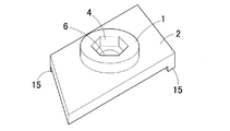
図1はこの発明の第1実施形態のボルト用座金の上面側から見た斜視図、図2は同座金を底面側から見た斜視図、図3はボルト3を挿入した状態を示す説明図である。
[First Embodiment]
1 is a perspective view of a bolt washer according to a first embodiment of the present invention as seen from the top surface side, FIG. 2 is a perspective view of the washer as seen from the bottom surface side, and FIG. 3 is an explanatory view showing a state in which the
このボルト用座金は、弾性変形可能な材質で一体に形成された上部1と下部2を有し、上部1は内側にボルト3の頭部3aが嵌合する上方に開口した嵌合穴4を有しており、下部2は板状であってその底面5を凹面としており、さらに前記嵌合穴4の底から下部2にボルト3の軸部3bを貫通させるためのボルト孔6を有するものとしている。
This bolt washer has an
このボルト用座金は、材質や製造方法は特に限定されないが、抗圧力・抗張力の高い高弾性体であることが望ましい。例えば、高い弾性を有する鋼材を、鍛造技術を利用することにより形成することができるが、その他にも、特殊鋼、非鉄合金(例えばベリリウムカッパー)、非金属材料(例えば炭素繊維とプラスチックの合成材)等を材料として、適宜の方法で製造することができる。 The material and manufacturing method of the bolt washer are not particularly limited, but it is desirable that the bolt washer be a high-elasticity body having high resistance and tensile strength. For example, a steel material having high elasticity can be formed by using a forging technique. In addition, special steel, non-ferrous alloy (for example, beryllium copper), non-metallic material (for example, synthetic material of carbon fiber and plastic) ) Etc. as a material, and can be produced by an appropriate method.
上部1は、短い六角柱の内側に上下方向の孔を穿ったような形状であり、その外周形状は六角形で、内周形状は外周形状を縮小した六角形であり、外周・内周の各対応する辺が平行になるようにしている。
The
上部1の内周形状、すなわち嵌合穴4の形状は、使用するボルト3の頭部3aの形状に応じたものとしている。この実施形態では、使用するボルト3の頭部3aは六角形であり、嵌合穴4の形状は、この頭部3aがほぼ隙間無く嵌合する六角形としている。また、嵌合穴4の深さは、締結時のボルト3の頭部3aの3分の1程度が上方に露出する程度(図3参照)としているが、これに限定されず、ボルト3の頭部3aが適宜の長さ上方に露出、あるいは嵌合穴4内に完全に埋没するようにしてもよい。
The inner peripheral shape of the
下部2は、上部1の径よりも大きな略円板状であり、その上面は、上部1の外周の外側の領域において露出している。この上面は、後述の底面5の凹曲面の曲率に対応した凸曲面としているが、平坦な面であっても良い。
The
下部2の底面5は被締結体と接する部分であるが、この底面5は、図2に示したように、平坦な面ではなく、凹面となっている。したがって、底面5におけるボルト孔6の周囲の領域は、締結時において、被締結体に接することなく、被締結体との間に空隙を有し離間した状態となる。図示した例においては、底面5は適宜の大きさの球面の一部に接するような凹曲面となっているが、これに限定されない。下部2の厚みや底面5の曲率は、求められる締結状態に応じて適宜設定することができる。
Although the
下部2の形状は、図示したような円板形に限定されず、被締結体に適応するように適宜設定することができる。例えば、楕円形、正方形あるいは矩形にしたり、さらに、後述の図6以下に示したように周囲に突出部を設けたり、縁部を折り曲げて断面略コ字状にしたりして、被締結体に係合させられるようにしてもよい。
The shape of the
また、上部1の嵌合穴4の底から下部2には、円形の孔が形成されており、これがボルト3の軸部3bを貫通させられるボルト孔6となっている。
Further, a circular hole is formed from the bottom of the
この座金は、使用状態においては、図3に示したように、上部1の嵌合穴4にボルト3の頭部3aが内蔵された構造になるので、ボルト3と一体的になり、従来の座金のようなボルト3と遊離したものとはならない。そのため、ボルト3の締め付け時ないし締め付け後に、座金とボルト3が相対回転して座金がボルト3の頭部3aによって削られたり、へたり・陥没が生じたりすることがなく、ボルト3の軸力の低下及びそれによるボルト3のゆるみが防止されることとなる。また、座金がボルト3の軸部3bのねじに当たってこれを磨耗させることもない。しかも、上部1と下部2とは一体であり、強靭かつ耐久性に優れたものとなっている。
As shown in FIG. 3, the washer has a structure in which the
また、上部1は、多角形(六角形)として外周形状がスパナーにより回転させられるようにした形状とすることにより、スパナーを使用して容易に増し締めすることが可能となっている。しかも、上部1はボルト3の頭部3aより一回り径が大きいため、通常のボルト3の頭部3aを回転させる場合よりも、強く締付けることが可能となる。なお、上部1は必ずしも多角形としてスパナーを使用できるようにする必要はなく、円形等でもよいが、ボルト3の頭部3aやナット7の形状に合わせて多角形とすることにより、見栄えを良くすることができる。
Moreover, the
また、この座金は、従来の座金とは全く異なる構造として、弾性変形に対する抵抗力を可及的に大きくし、ボルト3の適正軸力域に近づけようとするものであり、ボルト3の軸力を補償するとともに、被締結体との接合面における摩擦力を最大に活用することができる構造となっている。
In addition, this washer has a completely different structure from that of the conventional washer so that the resistance force against elastic deformation is increased as much as possible to bring it closer to the appropriate axial force region of the
すなわち、この座金は、全体が靭性の高い弾性体であり、弾性変形量が大きくなるので、ボルト3軸力の不足を十分に補うことが可能である。しかも、下部2の底面5が凹面となっているため、底面5の中央部付近には被締結体との間に空隙が生じ、底面5の外周付近の位置で主な摩擦力が発生するようになっている。この摩擦力が発生する位置は、回転の中心となるボルト3の軸からの距離(アーム)が最長となるので、摩擦トルクの値も最大となる(摩擦トルクは、多数箇所の接触面における摩擦力と回転中心までの距離との積の総和である)。したがって、座金のすべりを著しく少なくすることができ、さらに、摩擦面を特定できるので、摩擦係数を増大させるような加工も容易となる。
That is, this washer is an elastic body with high toughness as a whole, and the amount of elastic deformation becomes large, so that it is possible to sufficiently compensate for the shortage of the bolt triaxial force. In addition, since the
なお、下部2の厚みを大きくすれば、座金はより大きな弾性変形量を得ることができるとともに、非回転ゆるみを防止するスペーサー機能の効果が高まる。すなわち、下部2の厚みを大きくすることは、ボルト3の軸長及び被締結体の厚みも大きくすることとなり、ボルト3及び被締結体双方のばね定数を低下させ、ボルト3と被締結体の弾性変形量が増加するので、軸力の低下を防ぎ、締付け力の減少を少なくすることができる。
If the thickness of the
次に、この座金の具体的な使用例について説明する。 Next, a specific use example of this washer will be described.
〔使用例1〕
図4は、上下1対の座金とボルト3・ナット7により締結する場合の説明図であり、前記1対の座金の間に、上下に重なる2つの被締結体8,9を挟み、これらに形成したボルト孔8a,9aにボルト3を通して締結した状態を示している。ここで、上側の被締結体8は、ロータリ耕耘機のフランジ式の耕耘爪取り付け構造における耕耘爪、下側の被締結体9は、フランジとすることができる。
[Usage example 1]
FIG. 4 is an explanatory diagram in the case of fastening with a pair of upper and lower washers and
この例では、前記1対の座金のうち、上方の座金は、その上部1の嵌合穴4にボルト3の頭部3aが嵌合し、下部2の底面5が上側の被締結体8(耕耘爪)に接触するようにしている。他方、下方の座金は、上下逆向きにされ、その上部1の嵌合穴4に、前記ボルト3に螺合するナット7が嵌合し、下部2の底面5が下側の被締結体9(フランジ)に接触するようにしている。
In this example, of the pair of washers, the upper washer has the
各座金の下部2の底面5は、その中央部付近において被締結体8,9との間に空隙10が生じ、外周付近の位置が接触面となるようにしており、これによって大きな摩擦トルクが得られるので、ボルト3のゆるみを効果的に防止できる。
The
〔使用例2〕
図5はナットを使用せずに1つの座金とボルト3により締結する場合の説明図であり、上側の被締結体8に形成された孔8aにボルト3を通し、その下の被締結体9の板に形成された孔9aにボルト3が螺合した状態の断面を示している。
[Usage example 2]
FIG. 5 is an explanatory diagram in the case of fastening with one washer and the
このようにナットを使用せずにボルト3のみで締結を行う場合でも、この座金を使用すれば、座金の弾性変形によりボルト3の軸力低下を効果的に補償することができるとともに、下部2の底面5と被締結体8との間の空隙10の存在により、被締結体8との接合面における摩擦力を最大に活用することができるため、ボルト3のゆるみが効果的に防止される。
Even when fastening with only the
〔第2実施形態〕
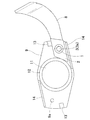
図6〜図9は、この発明の他の実施形態のボルト用座金を使用した耕耘爪の取り付け構造に関するものであり、図6は座金を上面側から見た斜視図、図7は同座金を底面側から見た斜視図、図8はこの座金を使用した耕耘爪の取り付け構造の分解状態の説明図、図9は1つの耕耘爪を締結した状態の説明図である。
[Second Embodiment]
FIGS. 6 to 9 relate to a mounting structure of a tilling claw using a bolt washer according to another embodiment of the present invention. FIG. 6 is a perspective view of the washer as seen from the upper surface side, and FIG. The perspective view seen from the bottom side, FIG. 8 is an explanatory view of the disassembled state of the mounting structure of the tilling claw using this washer, and FIG. 9 is the explanatory view of the state where one tilling claw is fastened.
この耕耘爪の取り付け構造は、座金、被締結体8(耕耘爪)、被締結体9(フランジ)、ボルト3及びナット7から構成されるものであり、上から座金、耕耘爪8及びフランジ9を配置して、これらにそれぞれ設けたボルト孔6,8a,9aに上方から下方へボルト3を通し、フランジの下方からボルト3にナット7を螺着させるようにしている。
This tilling claw attachment structure is composed of a washer, a fastened body 8 (cultivation claw), a fastened body 9 (flange), a
フランジ9は、その中央に位置する耕耘軸貫通孔11の周囲に、耕耘軸(図示せず)に外嵌する筒状部12を設けている。筒状部12は、フランジ9の耕耘爪取り付け面及びその裏面と垂直、すなわち耕耘軸の軸方向に延びるように形成されている。筒状部12には、耕耘爪8の端部が接触するようにしている。
The
また、フランジ9は、その耕耘爪取り付け面上において、ボルト孔9aよりも外周縁寄りの位置に耕耘爪8に被せた座金に当接する突起状の第1ストッパー13を有しており、これによって耕耘爪8に加わる負荷を吸収するようにしている。
The
さらに、フランジ9は、耕耘爪取り付け面上のボルト孔9aを挟んで第1ストッパー13の反対側に、筒状部12付近から縁部に至る直線壁状の第2ストッパー14を有している。この第2ストッパー14は、耕耘爪8に通常とは異なる大きさや方向の負荷が加わったときに、耕耘爪8に接触して負荷を吸収するようにしている。
Further, the
図示したように、フランジ9には、ボルト孔9a、第1ストッパー13、第2ストッパー14が、耕耘軸貫通孔11を中心として対称に2つ設けられている。図9においては、その片側だけに耕耘爪8を締結しているが、他方の側にも同様に耕耘爪8を締結することができる。
As shown in the figure, the
この第2実施形態の座金は、基本的な構造は図1等に示したものと同様であるが、下部2が耕耘爪8の基部の上面を覆う四角形状であって、一対の対角部に、下方に突出する突出部15を形成したものとしている。この座金は、下部2の底面5が耕耘爪8の基部の上面に接触するとともに、前記各突出部15が耕耘爪8の基部の側面に接触し、耕耘爪8との相対回動が防止されるようになっている。
The basic structure of the washer of the second embodiment is the same as that shown in FIG. 1 and the like, but the
〔その他の実施形態〕
また、この発明の座金は、前述のようなフランジ式の耕耘爪取り付け構造に限らず、特願2006−336698の図1や特開2007−159566(特願2005−333535)の図1に記載のような、2つの断面略コ字状の金具(爪保持具とカバー体)の組み合わせにより構成されるホルダー式の耕耘爪取り付け構造に適用することもできる。
[Other Embodiments]
The washer of the present invention is not limited to the flange-type tillage claw mounting structure as described above, and is described in FIG. 1 of Japanese Patent Application No. 2006-336698 and FIG. 1 of Japanese Patent Application Laid-Open No. 2007-159556 (Japanese Patent Application No. 2005-333535). The present invention can also be applied to a holder-type tilling claw attachment structure constituted by a combination of two fittings having a substantially U-shaped cross section (a claw holder and a cover body).
特開2007−159566の図1に記載のものを例にとると、2つの断面略コ字状の金具のうち、「カバー体11」(ボルトの頭部が接する方の金具)の代わりに、本願の図1等に記載の座金の下部2を断面略コ字状に形成して、「カバー体11」の「両側の側部11b,11c」に相当する部分を設けたものを使用すると良い。逆に、「保持具2」(ナットが接する方の金具)の代わりに、本願の図1等に記載の座金の下部2を断面略コ字状に形成して、「保持具2」の「両側の側部2b,2c」に相当する部分を設けたものを使用しても良い。この場合、前記2つの金具、及びこれらに挟まれる耕耘爪の基部が強固に締結されるので、前記座金と金具を溶接する必要はない。
Taking the example shown in FIG. 1 of Japanese Patent Application Laid-Open No. 2007-1559566 as an example, out of two brackets having a substantially U-shaped cross section, instead of “
特願2006−336698の図1に記載のものについても、前記特開2007−159566の図1に記載のものと同様に本願発明の座金を適用することができる。2つの金具のうち、いずれを本願発明の座金として適用するかについては、加工し易い方を選択するとよい。 The washer of the present invention can be applied to the one shown in FIG. 1 of Japanese Patent Application No. 2006-336698 as well as the one shown in FIG. As to which of the two metal fittings is applied as the washer of the present invention, the one that is easy to process may be selected.
以上がこの発明の実施形態であるが、この発明は、前述の実施形態に限定されるものではなく、産業機械その他様々な分野において実施することが可能であり、素材、形状、寸法等は適宜変更することができる。 The above is the embodiment of the present invention. However, the present invention is not limited to the above-described embodiment, and can be implemented in various fields such as industrial machinery. Can be changed.
1 上部
2 下部
3 ボルト
3a ボルトの頭部
3b ボルトの軸部
4 嵌合穴
5 底面
6 ボルト孔
DESCRIPTION OF
Claims (2)
Priority Applications (1)
| Application Number | Priority Date | Filing Date | Title |
|---|---|---|---|
| JP2007288188A JP4725898B2 (en) | 2007-11-06 | 2007-11-06 | Bolt washer |
Applications Claiming Priority (1)
| Application Number | Priority Date | Filing Date | Title |
|---|---|---|---|
| JP2007288188A JP4725898B2 (en) | 2007-11-06 | 2007-11-06 | Bolt washer |
Publications (3)
| Publication Number | Publication Date |
|---|---|
| JP2009115182A JP2009115182A (en) | 2009-05-28 |
| JP2009115182A5 JP2009115182A5 (en) | 2010-10-07 |
| JP4725898B2 true JP4725898B2 (en) | 2011-07-13 |
Family
ID=40782541
Family Applications (1)
| Application Number | Title | Priority Date | Filing Date |
|---|---|---|---|
| JP2007288188A Expired - Fee Related JP4725898B2 (en) | 2007-11-06 | 2007-11-06 | Bolt washer |
Country Status (1)
| Country | Link |
|---|---|
| JP (1) | JP4725898B2 (en) |
Families Citing this family (6)
| Publication number | Priority date | Publication date | Assignee | Title |
|---|---|---|---|---|
| WO2010122645A1 (en) * | 2009-04-22 | 2010-10-28 | Yamada Toru | Washer for bolt |
| JP2011089628A (en) * | 2009-10-26 | 2011-05-06 | Ihi Corp | Fastening member and supercharger |
| JP5548532B2 (en) * | 2010-06-22 | 2014-07-16 | 株式会社ヤマザキアクティブ | Locking washer |
| JP2015031399A (en) * | 2013-07-31 | 2015-02-16 | 有限会社エイチ・アイ・ケイ | Bolt rotation preventing washer |
| JP6230555B2 (en) * | 2015-02-06 | 2017-11-15 | 株式会社ベルテック | Other fixtures |
| JP7091123B2 (en) * | 2018-04-20 | 2022-06-27 | イワタボルト株式会社 | Fastening structure |
Citations (6)
| Publication number | Priority date | Publication date | Assignee | Title |
|---|---|---|---|---|
| JPS4523053Y1 (en) * | 1966-08-29 | 1970-09-11 | ||
| JPS62209209A (en) * | 1986-03-10 | 1987-09-14 | 川端 祥夫 | Method of incorporating sealing washer to nut |
| JPH0384208A (en) * | 1989-08-28 | 1991-04-09 | Asahi Denki Kk | Looseness preventing device for tightened part |
| JP3007180U (en) * | 1994-07-26 | 1995-02-07 | 不二サッシ株式会社 | Idling prevention washer |
| JPH0828539A (en) * | 1994-07-22 | 1996-02-02 | Ishikawajima Harima Heavy Ind Co Ltd | Shank nut |
| JP2004316701A (en) * | 2003-04-11 | 2004-11-11 | Sukejiro Nagata | Spring washer |
Family Cites Families (1)
| Publication number | Priority date | Publication date | Assignee | Title |
|---|---|---|---|---|
| JPS6019484U (en) * | 1983-07-19 | 1985-02-09 | 株式会社学習研究社 | writing utensil holder |
-
2007
- 2007-11-06 JP JP2007288188A patent/JP4725898B2/en not_active Expired - Fee Related
Patent Citations (6)
| Publication number | Priority date | Publication date | Assignee | Title |
|---|---|---|---|---|
| JPS4523053Y1 (en) * | 1966-08-29 | 1970-09-11 | ||
| JPS62209209A (en) * | 1986-03-10 | 1987-09-14 | 川端 祥夫 | Method of incorporating sealing washer to nut |
| JPH0384208A (en) * | 1989-08-28 | 1991-04-09 | Asahi Denki Kk | Looseness preventing device for tightened part |
| JPH0828539A (en) * | 1994-07-22 | 1996-02-02 | Ishikawajima Harima Heavy Ind Co Ltd | Shank nut |
| JP3007180U (en) * | 1994-07-26 | 1995-02-07 | 不二サッシ株式会社 | Idling prevention washer |
| JP2004316701A (en) * | 2003-04-11 | 2004-11-11 | Sukejiro Nagata | Spring washer |
Also Published As
| Publication number | Publication date |
|---|---|
| JP2009115182A (en) | 2009-05-28 |
Similar Documents
| Publication | Publication Date | Title |
|---|---|---|
| JP4725898B2 (en) | Bolt washer | |
| US7857566B2 (en) | Reactive fasteners | |
| EP3218615A1 (en) | Bolt with locked nut | |
| JP2009275727A (en) | Looseness preventing locking device | |
| WO2010122645A1 (en) | Washer for bolt | |
| US20150204374A1 (en) | Ratchet nut and washer | |
| US8444357B2 (en) | Providing a counter torque force within a fastening | |
| JP2014055637A (en) | Anti-loose washer | |
| JP2009115297A (en) | Lock-nut, its manufacturing method, and its jig for processing | |
| JP6332859B2 (en) | Resin washer | |
| JP2011033047A (en) | Lock nut and fastening structure thereof | |
| JP4945507B2 (en) | Clip nut | |
| JP6420300B2 (en) | Mounting bracket and bird net fitting | |
| JP2009144789A (en) | Clip nut | |
| JP2011127752A (en) | Lock washer | |
| JP2019039244A (en) | Exterior member mounting method | |
| JP6829356B2 (en) | Rod-shaped connector | |
| JP5276033B2 (en) | Fasteners | |
| JP2007147061A (en) | Fastening device and its seat | |
| JP4505844B2 (en) | Tillage claw mounting structure | |
| JP3104843U (en) | Anti-loosening device for rotating fasteners | |
| US12042715B2 (en) | Skateboard truck mounting apparatus | |
| JP2011169457A (en) | Temporary fastening member for bolt | |
| JP2006138365A (en) | Detent spring long plate and detent spring bolt | |
| JP3135378U (en) | Washer |
Legal Events
| Date | Code | Title | Description |
|---|---|---|---|
| A621 | Written request for application examination |
Free format text: JAPANESE INTERMEDIATE CODE: A621 Effective date: 20100615 |
|
| A521 | Written amendment |
Free format text: JAPANESE INTERMEDIATE CODE: A523 Effective date: 20100823 |
|
| A871 | Explanation of circumstances concerning accelerated examination |
Free format text: JAPANESE INTERMEDIATE CODE: A871 Effective date: 20100823 |
|
| A131 | Notification of reasons for refusal |
Free format text: JAPANESE INTERMEDIATE CODE: A131 Effective date: 20100922 |
|
| A975 | Report on accelerated examination |
Free format text: JAPANESE INTERMEDIATE CODE: A971005 Effective date: 20100916 |
|
| A521 | Written amendment |
Free format text: JAPANESE INTERMEDIATE CODE: A523 Effective date: 20101115 |
|
| A131 | Notification of reasons for refusal |
Free format text: JAPANESE INTERMEDIATE CODE: A131 Effective date: 20110106 |
|
| A01 | Written decision to grant a patent or to grant a registration (utility model) |
Free format text: JAPANESE INTERMEDIATE CODE: A01 Effective date: 20110317 |
|
| A61 | First payment of annual fees (during grant procedure) |
Free format text: JAPANESE INTERMEDIATE CODE: A61 Effective date: 20110401 |
|
| R150 | Certificate of patent or registration of utility model |
Free format text: JAPANESE INTERMEDIATE CODE: R150 |
|
| FPAY | Renewal fee payment (event date is renewal date of database) |
Free format text: PAYMENT UNTIL: 20140422 Year of fee payment: 3 |
|
| R250 | Receipt of annual fees |
Free format text: JAPANESE INTERMEDIATE CODE: R250 |
|
| R250 | Receipt of annual fees |
Free format text: JAPANESE INTERMEDIATE CODE: R250 |
|
| R250 | Receipt of annual fees |
Free format text: JAPANESE INTERMEDIATE CODE: R250 |
|
| R250 | Receipt of annual fees |
Free format text: JAPANESE INTERMEDIATE CODE: R250 |
|
| LAPS | Cancellation because of no payment of annual fees |