JP4725802B2 - Imaging apparatus, focusing method, and focusing program - Google Patents
Imaging apparatus, focusing method, and focusing program Download PDFInfo
- Publication number
- JP4725802B2 JP4725802B2 JP2006353204A JP2006353204A JP4725802B2 JP 4725802 B2 JP4725802 B2 JP 4725802B2 JP 2006353204 A JP2006353204 A JP 2006353204A JP 2006353204 A JP2006353204 A JP 2006353204A JP 4725802 B2 JP4725802 B2 JP 4725802B2
- Authority
- JP
- Japan
- Prior art keywords
- frame image
- face
- unit
- supply source
- evaluation value
- Prior art date
- Legal status (The legal status is an assumption and is not a legal conclusion. Google has not performed a legal analysis and makes no representation as to the accuracy of the status listed.)
- Expired - Fee Related
Links
Images


Classifications
-
- G—PHYSICS
- G06—COMPUTING; CALCULATING OR COUNTING
- G06V—IMAGE OR VIDEO RECOGNITION OR UNDERSTANDING
- G06V40/00—Recognition of biometric, human-related or animal-related patterns in image or video data
- G06V40/10—Human or animal bodies, e.g. vehicle occupants or pedestrians; Body parts, e.g. hands
- G06V40/16—Human faces, e.g. facial parts, sketches or expressions
- G06V40/161—Detection; Localisation; Normalisation
-
- H—ELECTRICITY
- H04—ELECTRIC COMMUNICATION TECHNIQUE
- H04N—PICTORIAL COMMUNICATION, e.g. TELEVISION
- H04N23/00—Cameras or camera modules comprising electronic image sensors; Control thereof
- H04N23/60—Control of cameras or camera modules
- H04N23/61—Control of cameras or camera modules based on recognised objects
- H04N23/611—Control of cameras or camera modules based on recognised objects where the recognised objects include parts of the human body
-
- H—ELECTRICITY
- H04—ELECTRIC COMMUNICATION TECHNIQUE
- H04N—PICTORIAL COMMUNICATION, e.g. TELEVISION
- H04N23/00—Cameras or camera modules comprising electronic image sensors; Control thereof
- H04N23/60—Control of cameras or camera modules
- H04N23/67—Focus control based on electronic image sensor signals
- H04N23/675—Focus control based on electronic image sensor signals comprising setting of focusing regions
Description
本発明は撮影装置の合焦に関する。 The present invention relates to focusing of a photographing apparatus.
特許文献1では、顔検出に用いた画像でAE/AF/AWBなどの制御を行い、被写体の動きやぶれが生じる場合の合焦精度を上げている。
In
特許文献2では、合焦時の被写体との推定距離から人物の顔サイズを特定し、特定したサイズで顔検出をすることで、顔検出時間を短縮する。 In Patent Document 2, the face detection time is shortened by specifying the face size of the person from the estimated distance from the subject at the time of focusing and detecting the face with the specified size.
特許文献3では、画像データと付属情報とから、顔検知領域を決定し、部分的に顔検知処理を実行する。
顔検出を行い、顔領域において自動焦点調節を行う技術は従来から知られている。しかし、従来技術では、顔検出に要する時間が必要であり、かつコントラストAFにおいてフォーカス位置を探索する時間も必要であるから、事前に検出された顔領域でAFを行うと、被写体の動きやぶれなどにより正確に顔に焦点を合わせることが困難であった。本発明は、被写体が動いたりぶれたりしたときも正確に顔に焦点を合わせる技術を提供することを目的とする。 A technique for performing face detection and performing automatic focus adjustment in a face area is conventionally known. However, since the conventional technique requires time for face detection and also requires time for searching for a focus position in contrast AF, if AF is performed on a face area detected in advance, subject movement, blurring, etc. It was difficult to focus on the face more accurately. An object of the present invention is to provide a technique for accurately focusing on a face even when a subject moves or shakes.
また、本発明は、フォーカスレンズを含む撮影光学系を介して受光した被写体像を画像データに変換する撮影部と、フォーカスレンズの合焦位置を調節する焦点調節部とを備える撮影装置であって、撮影部から順次供給されるコマ画像を一時的に格納する一時的格納部と、顔検出を行うコマ画像の供給元として一時的格納部または撮影部を選択する顔検出コマ画像供給元選択部と、顔検出コマ画像供給元選択部の選択したコマ画像の供給元から供給される第1のコマ画像から、人物の顔領域を検出する顔検出部と、顔検出部が第1のコマ画像から検出した顔領域の位置に基づいて、第1のコマ画像以降に供給される第2のコマ画像における顔領域の検出範囲を顔検出部に設定するとともに、顔検出部が第1のコマ画像から検出した顔領域のサイズを所定の縮小率で縮小したサイズを、第2のコマ画像における顔領域の検出サイズとして顔検出部に設定する顔検出設定部と、合焦評価値算出領域を設定するコマ画像の供給元として一時的格納部または撮影部を選択する合焦コマ画像供給元選択部と、顔検出部が第1のコマ画像から検出した顔領域の位置およびサイズと第2のコマ画像から検出した顔領域の位置およびサイズとを比較することで、顔領域の位置およびサイズの変動が所定の閾値未満であるか否かを判断し、変動が所定の閾値未満であると判断した場合は顔検出コマ画像供給元選択部および合焦コマ画像供給元選択部に撮影部を選択させ、変動が所定の閾値以上であると判断した場合は顔検出コマ画像供給元選択部および合焦コマ画像供給元選択部に一時的格納部を選択させる制御部と、顔検出部が第2のコマ画像から検出した顔領域の位置およびサイズに基づいて、合焦コマ画像供給元選択部の選択したコマ画像の供給元から供給された第3のコマ画像における合焦評価値の算出領域を設定する合焦領域設定部と、合焦領域設定部の設定した第3のコマ画像の合焦評価値の算出領域における画像データに基づいて合焦評価値を算出する算出部と、を備え、焦点調節部は、算出部の算出した合焦評価値に基づいて、フォーカスレンズの合焦位置を調節する。 The present invention is also a photographing apparatus including a photographing unit that converts a subject image received through a photographing optical system including a focus lens into image data, and a focus adjusting unit that adjusts a focus position of the focus lens. A temporary storage unit that temporarily stores frame images sequentially supplied from the shooting unit, and a face detection frame image supply source selection unit that selects a temporary storage unit or a shooting unit as a supply source of the frame image for face detection A face detection unit for detecting a face area of a person from a first frame image supplied from a frame image supply source selected by the face detection frame image supply source selection unit; based on the detected position of the face area, while setting the face detection unit detects the range of the face area that put the second frame image supplied after the first frame image, the face detection unit first The face area detected from one frame image The reduced size of's at a predetermined reduction ratio, and the face detection setting unit that sets the face detection section as the detection size of the face area in the second frame image, the supply source of the frame image for setting the focus evaluation value calculation region A focused frame image supply source selection unit that selects a temporary storage unit or a photographing unit as a position, a face region detected by the face detection unit from the first frame image, and a face region detected from the second frame image By comparing the position and size of the face area, it is determined whether or not the variation in the position and size of the face region is less than a predetermined threshold. If it is determined that the variation is less than the predetermined threshold, the face detection frame image When the photographing source is selected by the supply source selection unit and the focused frame image supply source selection unit and it is determined that the fluctuation is equal to or greater than a predetermined threshold, the face detection frame image supply source selection unit and the focused frame image supply source selection unit Select temporary storage for Based on the position and size of the face region detected by the face detection unit from the second frame image, and a third frame supplied from the frame image supply source selected by the focused frame image supply source selection unit Focus evaluation based on the image data in the focus evaluation value calculation area of the third frame image set by the focus area setting section and the focus area setting section that sets the calculation area of the focus evaluation value in the frame image And a focus adjustment unit that adjusts the focus position of the focus lens based on the focus evaluation value calculated by the calculation unit.
この発明によると、顔領域の位置およびサイズの変動の大小に応じて、撮影部からのコマ画像または一時的格納部のコマ画像のいずれで顔検出を行うかを選択する。すなわち、顔領域の変動が大きければ一時的格納部のコマ画像を用いることで、顔検出の正確性を確保できる。一方、顔領域の変動が小さければ、一時的格納部でなく撮影部からのコマ画像で顔検出を行うから、電力消費を抑えつつ、顔検出の正確性も可及的に確保できる。 According to the present invention, it is selected whether to perform face detection on the frame image from the photographing unit or the frame image in the temporary storage unit according to the size of the position and size of the face region. That is, if the variation of the face area is large, the accuracy of face detection can be ensured by using the frame image in the temporary storage unit. On the other hand, if the variation of the face area is small, the face detection is performed not by the temporary storage unit but by the frame image from the photographing unit, so that the accuracy of the face detection can be ensured as much as possible while suppressing power consumption.
本発明は、フォーカスレンズを含む撮影光学系を介して受光した被写体像を画像データに変換する撮影部を備える撮影装置で用いられる合焦方法であって、撮影部から順次供給されるコマ画像を一時的格納媒体に格納するステップと、顔検出を行うコマ画像の供給元として一時的格納媒体または撮影部を選択するステップと、選択した顔検出を行うコマ画像の供給元から供給される第1のコマ画像から、人物の顔領域を検出するステップと、第1のコマ画像から検出した顔領域の位置に基づいて、第1のコマ画像以降に供給される第2のコマ画像における顔領域の検出範囲を設定するとともに、第1のコマ画像から検出した顔領域のサイズを所定の縮小率で縮小したサイズを、第2のコマ画像における顔領域の検出サイズとして設定するステップと、合焦評価値算出領域を設定するコマ画像の供給元として一時的格納媒体または撮影部を選択するステップと、第1のコマ画像から検出した顔領域の位置およびサイズと第2のコマ画像から検出した顔領域の位置およびサイズとを比較することで、顔領域の位置およびサイズの変動が所定の閾値未満であるか否かを判断し、変動が所定の閾値未満であると判断した場合は顔検出を行うコマ画像の供給元および合焦評価値算出領域を設定するコマ画像の供給元として撮影部を選択し、変動が所定の閾値以上であると判断した場合は顔検出を行うコマ画像の供給元および合焦評価値算出領域を設定するコマ画像の供給元として一時的格納媒体を選択するステップと、第2のコマ画像から検出した顔領域の位置およびサイズに基づいて、選択された合焦評価値算出領域を設定するコマ画像の供給元から供給された第3のコマ画像における合焦評価値の算出領域を設定するステップと、設定した第3のコマ画像の合焦評価値の算出領域における画像データに基づいて合焦評価値を算出するステップと、算出した合焦評価値に基づいて、フォーカスレンズの合焦位置を調節するステップと、を含む。 The present invention relates to a focusing method used in a photographing apparatus including a photographing unit that converts a subject image received through a photographing optical system including a focus lens into image data, and frame images sequentially supplied from the photographing unit are obtained. The step of storing in the temporary storage medium, the step of selecting the temporary storage medium or the photographing unit as the supply source of the frame image for performing face detection, and the first supplied from the supply source of the frame image for performing the selected face detection face from the frame image, and detecting a face region of a person, based on the detected position of the face area from the first frame image, that put the second frame image supplied after the first frame image sets a detection range of a region, stearyl to size with the size of the detected face area from the first frame image is reduced at a predetermined reduction ratio, as the detection size of the face area in the second frame image Flop and, selecting a temporary storage medium or imaging section as the supply source of the frame image for setting the focus evaluation value calculation region, the position and size and the second frames of the detected face area from the first frame image By comparing the position and size of the face area detected from the image, it is determined whether the variation in the position and size of the face area is less than a predetermined threshold, and the fluctuation is determined to be less than the predetermined threshold. In this case, the photographing unit is selected as a frame image supply source for performing face detection and a frame image supply source for setting a focus evaluation value calculation area, and face detection is performed when it is determined that the fluctuation is equal to or greater than a predetermined threshold. selecting a temporary storage medium as a supply source of the frame image to set the source and focus evaluation value calculation region of the frame image, based on the position and size of the detected face area from the second frame image, selection Setting a calculation region of the focus evaluation value in the third frame image supplied a focus evaluation value calculation region from sources frame image set, focus evaluation of the third frame image set Calculating a focus evaluation value based on image data in a value calculation region; and adjusting a focus position of the focus lens based on the calculated focus evaluation value.
本発明によると、第1のコマ画像で検出された顔領域の位置およびサイズから、以降の第2のコマ画像で検出する顔領域の位置およびサイズを限定するから、顔検出までに要する時間を大幅に短縮することができ、結果的に、顔に対する合焦の精度を向上させることができる。 According to the present invention, since the position and size of the face area detected in the subsequent second frame image are limited from the position and size of the face area detected in the first frame image, the time required for face detection is reduced. As a result, the accuracy of focusing on the face can be improved.
本発明によると、顔領域を検出するコマ画像および合焦評価値算出領域を設定するコマ画像は、同一(第2のコマ画像)であるから、合焦評価値の算出対象領域を検出された顔領域と一致させることができ、顔に対する正確な合焦調節ができる。しかも、第1のコマ画像で検出された顔領域の位置およびサイズから、以降の第2のコマ画像で検出する顔領域の位置およびサイズを限定するから、顔検出までに要する時間を大幅に短縮することができ、正確かつ素早い合焦調節ができる。 According to the present invention, since the frame image for detecting the face area and the frame image for setting the focus evaluation value calculation area are the same (second frame image), the calculation target area of the focus evaluation value is detected. It can be made to coincide with the face area, and accurate focus adjustment for the face can be performed. Moreover, since the position and size of the face area detected in the subsequent second frame image are limited from the position and size of the face area detected in the first frame image, the time required for face detection is greatly reduced. Can be adjusted accurately and quickly.
本発明によると、顔領域の位置およびサイズの変動の大小に応じて、撮影部からのコマ画像または一時的格納部のコマ画像のいずれで顔検出を行うかを選択する。すなわち、顔領域の変動が大きければ一時的格納部のコマ画像を用いることで、顔検出の正確性を確保できる。一方、顔領域の変動が小さければ、一時的格納部でなく撮影部からのコマ画像で顔検出を行い、電力消費を抑えつつ、顔検出の正確性も可及的に確保できる。 According to the present invention, it is selected whether to perform face detection using a frame image from the photographing unit or a frame image from the temporary storage unit according to the size of the position and size of the face region. That is, if the variation of the face area is large, the accuracy of face detection can be ensured by using the frame image in the temporary storage unit. On the other hand, if the variation of the face area is small, face detection is performed with the frame image from the photographing unit instead of the temporary storage unit, and the accuracy of face detection can be ensured as much as possible while suppressing power consumption.
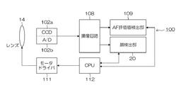
図1は、本発明の好ましい第1の実施形態に係るデジタルカメラ100の要部ブロック図である。まず、同図のデジタルカメラ100において、中央処理装置(CPU)112は、レリーズスイッチやモードダイヤル等の各種のボタンやキーからの入力に基づいてデジタルカメラ100内の各回路を統括制御する。
FIG. 1 is a principal block diagram of a
また、デジタルカメラ100は、撮像レンズ(フォーカスレンズおよびズームレンズを含む)14からの被写体光を光電変換してアナログ画像信号を出力するCCD102a、CCD102aからのアナログ信号に対してCDS処理・ゲイン処理などを行うとともに、デジタルのR,G,B画像データにA/D変換するA/D変換部102bを含むAFE(アナログフロントエンド回路)102を備える。
In addition, the
モードダイヤルなどによって静止画撮影モードが設定されると、CPU112は、動画(スルー画)を表示部に表示させ、撮影画角を確認可能にする。即ち、撮像レンズ14を通過した光は、CCD102aに入射する。CCD102aの受光面には、フォトセンサが平面的に配列されており、該受光面上の有効画素領域に結像された被写体像は、各フォトセンサによって入射光量に応じた量の信号電荷に変換される。こうして蓄積された信号電荷は、図示せぬドライバ回路から与えられるパルス信号に基づいて信号電荷に応じた電圧信号(画像信号)として順次読み出され、それぞれA/D変換部102bに加えられる。
When the still image shooting mode is set by a mode dial or the like, the
A/D変換部102bは、供給された画像信号をデジタル画像データに変換し、撮像回路108に出力する。
The A /
撮像回路108は、ホワイトバランス補正回路、ガンマ補正回路、YC処理回路、輝度・色差信号生成回路、シャープネス補正回路、コントラスト補正回路、撮影画像に対する輪郭補正を含む画像処理を行う輪郭処理部、画像のノイズ低減処理を行うノイズ低減処理部等を含む画像処理手段であり、CPU112からのコマンドに従って画像データを処理する。
The
図示は省略するが、撮像回路108から出力された画像データは、輝度信号(Y信号)及び色差信号(Cr、Cl信号)に変換されるとともに、ガンマ補正等の所定の処理が施された後、図示しないVRAMに格納される。
Although illustration is omitted, the image data output from the
顔検出部20は、撮像回路108から逐次出力されるデジタル画像データ(スルー画像)から人物の顔部分を含む領域である顔領域を検出する。顔領域の検出方法としては、例えば本出願人による特開平9−101579号公報において開示された技術を適用することができる。
The
この技術は、撮影した画像の各画素の色相が肌色の範囲に含まれるか否かを判定して肌色領域と非肌色領域とに分割すると共に、画像中のエッジを検出して画像中の各箇所をエッジ部分又は非エッジ部分に分類する。そして、肌色領域内に位置し非エッジ部分に分類された画素からなり、かつエッジ部分と判定された画素で囲まれた領域を顔候補領域として抽出し、抽出した顔候補領域が人物の顔に相当する領域かを判定し、この判定結果に基づき顔領域として検出するものである。また、この他に、特開2003−209683号公報や特開2002−199221号公報に記載される方法で顔領域を検出することもできる。 This technology determines whether or not the hue of each pixel of the captured image is included in the skin color range and divides it into a skin color region and a non-skin color region, and detects edges in the image to detect each pixel in the image. The location is classified as an edge portion or a non-edge portion. Then, an area surrounded by pixels that are located in the skin color area and classified as a non-edge part and surrounded by pixels that are determined to be edge parts is extracted as a face candidate area, and the extracted face candidate area becomes a human face. It is determined whether the region is a corresponding region, and is detected as a face region based on the determination result. In addition to this, a face region can also be detected by a method described in Japanese Patent Application Laid-Open Nos. 2003-209683 and 2002-199221.
一方、A/D変換部102bでデジタル信号に変換された画像データは、図示しないハイパスフィルタ(HPF)でG画素成分のみ抽出される。そして、図示しない積算処理部で抽出されたG画素成分に積算処理が施されてAF評価値検出部109に送られる。
On the other hand, only the G pixel component is extracted from the image data converted into a digital signal by the A /
AF評価値検出部109は、積算処理部から送られた1画面分のG画素成分積算値の内、顔検出部20が検出した顔領域に基づいて評価値算出エリアを設定し、該エリアにおける積算値の平均値を算出して、これをオートフォーカス(AF)評価値とする。AF評価値は、所定周期の経過毎に算出され、算出の度に更新記憶される。この評価値算出エリアの設定の仕方は後述する。
The AF evaluation
CPU112は、AF評価値検出部109の算出したAF評価値に従って被写体の合焦を判定する。その判断方法は任意であるが、例えばAF評価値が極大点の近傍に略到達しているか否かを判断し、極大点に略達している場合は合焦していると判断し、その他の場合は合焦していないと判断する。あるいは、AF評価値が所定の閾値を超えていれば合焦していると判断することもできる。
The
AF評価値検出部109は、CPU112がモータドライバ111を駆動制御してレンズ14を可動範囲内、即ち無限遠側の端点(INF点)から至近側の端点(NEAR点)の間で移動させている間に順次振幅値の計算を実行し、最大振幅を検出した時に検出値をCPU112に送信する。
The AF evaluation
CPU112は、この検出値を取得して対応する合焦位置に、レンズ14を移動させるようにモータドライバ111に指令を出す。モータドライバ111は、CPU112の指令に応じてレンズ14を合焦位置に移動させる。これは一般的に、自動焦点調節動作(AF動作)と呼ばれる。
The
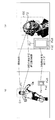
図2は、本実施形態に係るAF動作のシーケンスを示す図である。 FIG. 2 is a diagram showing a sequence of AF operation according to the present embodiment.
まず、撮影モードの設定に合わせ、CCD102aからの継続的なコマ画像(スルームービー)MV1、MV2、・・の供給が開始すると、撮像回路108から順次供給されるスルームービーに合わせて、撮像回路108における画像処理が行われる。画像処理されたスルームービーはVRAMに一旦格納され、所定形式の映像信号(例えば、NTSC方式のカラー複合映像信号)に変換されて、図示しない表示系に逐次供給される。
First, when supply of continuous frame images (through movies) MV1, MV2,... From the
一方、レリーズスイッチの半押し(S1オン)が検知されると、顔検出部20は、撮像回路108から供給されたスルームービーから顔検出を試みる。この結果、顔の存在領域(顔領域)が検出される。
On the other hand, when the half-press of the release switch (S1 ON) is detected, the
AF評価値検出部109は、検出された顔領域の位置に基づき、次に供給されるスルームービーにおける顔領域の検出範囲を設定する。同時に、AF評価値検出部109は、検出された顔領域のサイズを所定の縮小率で縮小したサイズを、次に供給されるスルームービーにおける検出顔サイズに設定する。AF評価値検出部109は、次回に供給されたスルームービーのうち、設定された顔領域検出範囲内で、設定されたサイズの顔領域を検出する。従って、いわゆる全域サーチは行わず、顔領域検出範囲および顔領域のサイズは、顔検出の度に制限される。
The AF evaluation
例えば図3(a)のようなデフォルトの検出顔サイズの顔領域F1、あるいは図3(b)のようなデフォルトの顔サイズの顔領域F2が、被写体の顔の近傍位置で検出されたとする。 For example, assume that a face area F1 having a default detected face size as shown in FIG. 3A or a face area F2 having a default face size as shown in FIG. 3B is detected in the vicinity of the face of the subject.
この場合、図3(a)のような矩形の顔領域F1に対しては、顔領域F1と同一の中心座標を有する所定サイズの矩形領域D1を、次回のスルームービーにおける顔領域検出範囲とする。あるいは、図3(b)のような矩形の顔領域F2に対しては、顔領域F2と同一の中心座標を有する所定サイズ矩形領域D2を、次回のスルームービーにおける顔領域検出範囲とする。
In this case, with respect to the rectangular face areas F1 as in FIG. 3 (a), a
なお、次に供給されるスルームービーにおける顔検出範囲のサイズは任意である。図3(a)・図3(b)では一例として、矩形領域D1・D2のサイズは、それぞれ該顔領域F1・F2を4倍したものとなっている。 Note that the size of the face detection range in the next through-movie to be supplied next is arbitrary. 3A and 3B, as an example, the sizes of the rectangular areas D1 and D2 are four times the face areas F1 and F2, respectively.
さらに、例えば図3(a)・図3(b)のような検出顔サイズの顔領域Fa1・Fb1が検出された場合、Fa1・Fb1を所定の倍率(例えば0.8倍)だけ縮小した検出顔サイズの顔領域Fa2・Fb2を、次に供給されるスルームービーにおける検出顔サイズに設定する。 Further, for example, when face areas Fa1 and Fb1 having detected face sizes as shown in FIGS. 3A and 3B are detected, detection is performed by reducing Fa1 and Fb1 by a predetermined magnification (for example, 0.8 times). The face areas Fa2 and Fb2 of the face size are set to the detected face size in the next through movie to be supplied.
次回のスルームービーにおける顔検出範囲は、スルームービー供給から顔検出完了までのタイムラグにおける被写体の顔領域の移動範囲がカバーされるよう決定されることが好ましい。 The face detection range in the next through movie is preferably determined so as to cover the moving range of the face area of the subject in the time lag from the through movie supply to the completion of face detection.
例えば、被写体の動きベクトルを算出し、現在の顔検出領域を動きベクトル検出に沿って移動した矩形領域を、次回のスルームービーにおける顔検出範囲としてもよい。このように被写体の位置と動きを考慮して次回のスルームービーにおける顔検出範囲を決定してもよい。 For example, a rectangular area obtained by calculating the motion vector of the subject and moving the current face detection area along the motion vector detection may be used as the face detection range in the next through movie. In this way, the face detection range in the next through movie may be determined in consideration of the position and movement of the subject.
ただし、顔検出範囲が小さければ小さいほど、次回のスルームービーにおける顔検出が高速になる。従って、本実施形態の顔検出AFは、2コマ分のタイムラグ間における被写体の動きがあまり激しくなく、より小さい顔検出範囲を設定できる場合に、特に正確性の効果を発揮する。 However, the smaller the face detection range, the faster the face detection in the next through movie. Therefore, the face detection AF of the present embodiment is particularly effective when the movement of the subject between the time lags of two frames is not so intense and a smaller face detection range can be set.
説明の簡略のため、上記のタイムラグの間における顔領域の移動範囲が、次に供給されるスルームービーにおける顔検出範囲内であるとする。 For the sake of simplicity of explanation, it is assumed that the movement range of the face area during the above time lag is within the face detection range in the next through movie to be supplied.
以後、スルームービー供給の度に、次回のスルームービーにおける顔検出範囲の決定および検出顔領域の縮小を繰り返す。図3(a)に示すように、あるスルームービーで顔領域Fa1が検出されると、次回以降のスルームービーの検出顔領域のサイズは、Fa2、Fa3・・と順次に縮小されていく。また、図3(b)に示すように、あるスルームービーで顔領域Fb1が検出されると、次回以降のスルームービーの検出顔領域のサイズは、Fb2、Fb3・・と順次に縮小されていく。 Thereafter, each time a through movie is supplied, determination of the face detection range and reduction of the detected face area in the next through movie are repeated. As shown in FIG. 3A, when the face area Fa1 is detected in a certain through movie, the size of the detected face area of the through movie from the next time onward is sequentially reduced to Fa2, Fa3,. As shown in FIG. 3B, when the face area Fb1 is detected in a certain through movie, the size of the detected face area of the through movie after the next time is sequentially reduced to Fb2, Fb3,. .
この場合、顔検出部20は、順次決定された顔検出範囲内で、限定された顔領域の検出を試み、限定された範囲で効率的に限定された大きさの顔領域の検出がされるから、スルームービー供給から顔検出完了までのタイムラグ時間が大幅に短縮され、顔検出の即時性が確保される(図2(b)参照)。
In this case, the
そして、AF評価値検出部109は、順次縮小されたサイズの検出顔領域に対するAF評価値のピークを顔検出以降のスルームービーから探索し、顔に対してピントを合わせる。
Then, the AF evaluation
本実施形態では、あるスルームービーAFn(n=1、2・・)から検出された顔領域を基準にして、スルームービーAFn+2のピント合わせ(顔検出AF)が行うことができるから、顔へのピント合わせの正確性が従来よりも確保できることに注意を要する。 In the present embodiment, the focus of the through movie AFn + 2 (face detection AF) can be performed based on the face area detected from a certain through movie AFn (n = 1, 2,...). It should be noted that the accuracy of focusing can be ensured more than before.
すなわち、図2(a)に示すように、S1オン前の顔検出では、顔検出部20が撮像回路108からスルームービーの供給を受けたときからそのスルームービーについて顔検出が完了するまでに要した時間に相当するタイムラグ(ここでは3コマ分)が生じる。例えば顔検出部20が「MV1」について顔検出を完了したときには、撮像回路108から「MV4」の供給が開始している。従来の顔検出では、いわば、「MV1」について検出された顔領域が、3コマ後の「MV4」における顔検出AFに利用されるため、顔へのピント合わせが正確とは言えない。
That is, as shown in FIG. 2A, in the face detection before S1 is turned on, it is necessary from the time when the
一方、図2(b)に示すように本実施形態の顔検出によると、例えば顔検出部20がスルームービー「AF1」について顔検出を完了したときには、撮像回路108から「AF3」の供給は完了していない。従って、「AF1」について検出された顔領域は、2コマ後の「AF3」におけるピント合わせに利用することができる。このように、顔検出からピント合わせまでのタイムラグが従来の顔検出AFよりも小さく、顔へのピント合わせが正確である。
On the other hand, according to the face detection of the present embodiment as shown in FIG. 2B, for example, when the
本実施形態では上記のような顔検出からピント合わせまでのタイムラグを短縮しうるが、完全にタイムラグを除去する方法は、以下の第2実施形態で説明する。 In this embodiment, the time lag from face detection to focusing as described above can be shortened, but a method for completely removing the time lag will be described in the second embodiment below.
<第2実施形態>
図4は第2実施形態に係るカメラ200のブロック図である。このカメラ200は、第1実施形態のカメラ100と共通する構成を一部有しているが、さらに、SDRAMコントローラ75、SDRAM74、DMAC(ダイレクトメモリアクセスコントローラ)81、表示回路83、信号処理部110を備えている。
Second Embodiment
FIG. 4 is a block diagram of a
信号処理部110は、撮像回路108から入力されたCCD−RAW画像データをYC信号に変換し、得られたYC信号を、DMAC81がいったんSDRAMコントローラ75に転送し、SDRAM74に書き込まれる。その上で、DMAC81は、SDRAMコントローラ75がSDRAM74から読み出したYC信号を、表示回路83、AF評価値検出部109あるいは顔検出部20に転送する。
The
DMAC81経由でSDRAM74から表示回路83に転送されたYC信号は、表示回路83で表示用の所定方式の信号(例えば、NTSC方式のカラー複合映像信号)に変換された後、LCDやテレビなどの表示装置に出力され、CCD102aで撮影した画像を映像として出力することが可能である。
The YC signal transferred from the
図5は、本実施形態に係るAF動作のシーケンスを示す図である。 FIG. 5 is a diagram showing a sequence of AF operation according to the present embodiment.
図5(a)は、図2(a)と同様、S1オン前のスルームービー出力・表示・顔検出を示す。 FIG. 5A shows through-movie output / display / face detection before S1 is turned on, as in FIG. 2A.
図5(b)は、S1オン後のムービースルー画出力・表示・顔検出を示す。 FIG. 5B shows movie through image output / display / face detection after S1 is turned on.
まず、DMAC81は、SDRAM74から継続的に読み出されたスルームービーを順次顔検出部20へ転送する。顔検出部20は、DMAC81経由でスルームービーを受け取ると、第1実施形態と同様、顔検出と次回の顔検出範囲・サイズの設定とを行う。
First, the
DMAC81は、顔検出部20が顔検出を行うべきスルームービーと同一のスルームービーを、AF評価値検出部109にも転送している。
The
AF評価値検出部109は、DMAC81から転送を受けたスルームービーについて、顔検出部20の検出した顔領域を評価値算出エリアに設定し、該エリアからAF評価値を算出し、合焦位置を探索する。
For the through movie transferred from the
第1実施形態では、顔検出されたスルームービーはAFn、評価値算出エリアの設定されるスルームービーはAFn+2であったが、本実施形態では第1実施形態と異なり、評価値算出エリアの設定されるスルームービーが、顔検出されたスルームービーと一致している。従って、検出された顔領域をそのまま評価値算出エリアとすれば、顔に対して正確に焦点を合わせることができる。 In the first embodiment, the face-detected through movie is AFn and the through-movie in which the evaluation value calculation area is set is AFn + 2. However, in this embodiment, the evaluation value calculation area is set unlike the first embodiment. The through movie that matches the through movie with the face detected. Therefore, if the detected face area is used as the evaluation value calculation area as it is, the face can be accurately focused.
<第3実施形態>
第1実施形態のカメラ100は、回路構成が単純であり、電力消費が小さいというメリットがある。一方、第2実施形態のカメラ200は、電力消費は大きいが、顔に対する合焦が正確であるというメリットがある。本実施形態では、この双方のメリットを備えるカメラを提供する。
<Third Embodiment>
The
図6は第3実施形態に係るカメラ300のブロック図である。この構成の一部は、第1・2実施形態と同様であるが、顔検出部20は選択部20aを、AF評価値検出部109は選択部109aを備えている。
FIG. 6 is a block diagram of a
選択部20aは、顔検出部20へのスルームービーの供給元を、撮像回路108またはSDRAM74のいずれか一方に選択する機能を有する。選択部20aがスルームービーの供給元を撮像回路108に選択した場合、顔検出部20は、第1実施形態と同様、撮像回路108からのスルームービーから顔検出を行う。選択部20aがスルームービーの供給元をSDRAM74に選択した場合、顔検出部20は、第2実施形態と同様、SDRAM74からDMAC81を経由して供給されたスルームービーから顔検出を行う。
The
一方、選択部109aは、AF評価値検出部109へのスルームービーの供給元を、撮像回路108またはSDRAM74のいずれか一方に選択する機能を有する。選択部109aがスルームービーの供給元を撮像回路108に選択した場合、AF評価値検出部109は、第1実施形態と同様、撮像回路108からのスルームービーからAF評価値の算出を行う。選択部109aがスルームービーの供給元をSDRAM74に選択した場合、AF評価値検出部109は、第2実施形態と同様、SDRAM74からDMAC81を経由して供給されたスルームービーからAF評価値の算出を行う。
On the other hand, the
選択部20aおよび選択部109aによるスルームービーの供給元の選択は、CPU112が制御する。
The
すなわち、まずCPU112は、スルームービーの供給元として、選択部20aに撮像回路108を選択させる。
That is, first, the
S1オンとなった場合、顔検出部20は、撮像回路108からのスルームービーから顔検出と次回のスルームービーの顔検出範囲・サイズの設定を行う。
When S1 is turned on, the
CPU112は、顔検出部20が前回検出した顔領域の位置およびサイズと今回検出した顔領域の位置およびサイズとを比較し、顔領域の位置・サイズの変動が所定の大きさ未満(例えば両顔領域の中心座標間の距離が、前回検出された顔領域の対角線の長さの半分未満であり、かつサイズ比が10%未満)であるか否かを判断する。
The
CPU112は、顔領域の位置・サイズの変動が所定の大きさ未満であると判断した場合、スルームービーの供給元として、選択部20aに撮像回路108を選択させるとともに、選択部109aに撮像回路108を選択させる。以後、第1実施形態と同様の合焦位置探索が行われる。これは、顔の位置・サイズの変動があまり大きくない場合、第1実施形態のような顔検出AFでも十分正確性を確保できると考えられるからである。そして、この場合、SDRAM74からAF評価値検出部109へのスルームービー供給がカットされるから、無駄な電力消費を減らすことができる。
When the
一方、CPU112は、顔領域の位置・サイズの変動が所定の大きさ未満でないと判断した場合、スルームービーの供給元として、選択部20aにSDRAM74を選択させるとともに、選択部109aにSDRAM74を選択させる。以後、第2実施形態と同様の合焦位置探索が行われる。これは、顔の位置変動が大きい場合、第2実施形態のような顔検出AFで正確性を確保する必要があるからである。
On the other hand, if the
以後、レリーズスイッチの全押し(S2オン)がされるまで、上記のような顔領域の位置・サイズ変動の判断およびスルームービー供給元の選択を繰り返す。 Thereafter, until the release switch is fully pressed (S2 is turned on), the determination of the position / size variation of the face area and the selection of the through movie supply source are repeated.
このように、顔の位置・サイズの変動の大小に応じて顔検出部20・AF評価値検出部109へのスルームービー供給元を変えることで、省電力化と顔検出AFの正確性のバランスを保つことができる。
In this way, by changing the through movie supply source to the
Claims (3)
前記撮影部から順次供給されるコマ画像を一時的に格納する一時的格納部と、顔検出を行うコマ画像の供給元として前記一時的格納部または前記撮影部を選択する顔検出コマ画像供給元選択部と、
前記顔検出コマ画像供給元選択部の選択したコマ画像の供給元から供給される第1のコマ画像から、人物の顔領域を検出する顔検出部と、
前記顔検出部が前記第1のコマ画像から検出した顔領域の位置に基づいて、前記第1のコマ画像以降に供給される第2のコマ画像における顔領域の検出範囲を前記顔検出部に設定するとともに、前記顔検出部が前記第1のコマ画像から検出した顔領域のサイズを所定の縮小率で縮小したサイズを、前記第2のコマ画像における顔領域の検出サイズとして前記顔検出部に設定する顔検出設定部と、
合焦評価値算出領域を設定するコマ画像の供給元として前記一時的格納部または前記撮影部を選択する合焦コマ画像供給元選択部と、
前記顔検出部が前記第1のコマ画像から検出した顔領域の位置およびサイズと前記第2のコマ画像から検出した顔領域の位置およびサイズとを比較することで、顔領域の位置およびサイズの変動が所定の閾値未満であるか否かを判断し、前記変動が所定の閾値未満であると判断した場合は前記顔検出コマ画像供給元選択部および前記合焦コマ画像供給元選
択部に前記撮影部を選択させ、前記変動が所定の閾値以上であると判断した場合は前記顔検出コマ画像供給元選択部および前記合焦コマ画像供給元選択部に前記一時的格納部を選択させる制御部と、
前記顔検出部が前記第2のコマ画像から検出した顔領域の位置およびサイズに基づいて、前記合焦コマ画像供給元選択部の選択したコマ画像の供給元から供給された第3のコマ画像における合焦評価値の算出領域を設定する合焦領域設定部と、
前記合焦領域設定部の設定した前記第3のコマ画像の合焦評価値の算出領域における画像データに基づいて合焦評価値を算出する算出部と、
を備え、
前記焦点調節部は、前記算出部の算出した合焦評価値に基づいて、前記フォーカスレンズの合焦位置を調節する撮影装置。 An imaging apparatus comprising: an imaging unit that converts a subject image received through an imaging optical system including a focus lens into image data; and a focus adjustment unit that adjusts an in- focus position of the focus lens,
A temporary storage unit that temporarily stores frame images sequentially supplied from the imaging unit; and a face detection frame image supply source that selects the temporary storage unit or the imaging unit as a supply source of the frame image for performing face detection. A selection section;
A face detection unit for detecting a face area of a person from a first frame image supplied from a frame image supply source selected by the face detection frame image supply source selection unit;
Based on the position of the face detection unit detects from the first frame image face area, the detection range of the put that the face area in the second frame image supplied after the first frame image the face while setting the detection unit, the size of the face detection unit has reduced the size of the first face area detected from the frame image at a predetermined reduction ratio, as the detection size of the face area in the second frame image A face detection setting unit to be set in the face detection unit;
A focused frame image supply source selection unit that selects the temporary storage unit or the photographing unit as a frame image supply source for setting a focus evaluation value calculation region;
By comparing the position and size of the face area detected from the first frame image with the position and size of the face area detected from the second frame image by the face detection unit, the position and size of the face area are compared. It is determined whether or not the variation is less than a predetermined threshold, and when it is determined that the variation is less than the predetermined threshold, the face detection frame image supply source selection unit and the focused frame image supply source selection unit A control unit that selects an imaging unit and causes the face detection frame image supply source selection unit and the focused frame image supply source selection unit to select the temporary storage unit when it is determined that the variation is equal to or greater than a predetermined threshold. When,
Based on the position and size of the face area detected by the face detection unit from the second frame image, the third frame image supplied from the supply source of the frame image selected by the focused frame image supply source selection unit An in-focus area setting unit for setting an in-focus evaluation value calculation area in
A calculation unit that calculates a focus evaluation value based on image data in a calculation region of a focus evaluation value of the third frame image set by the focus region setting unit;
With
The focus adjustment unit adjusts the in- focus position of the focus lens based on the focus evaluation value calculated by the calculation unit.
前記撮影部から順次供給されるコマ画像を一時的格納媒体に格納するステップと、
顔検出を行うコマ画像の供給元として前記一時的格納媒体または前記撮影部を選択するステップと、
選択した顔検出を行うコマ画像の供給元から供給される第1のコマ画像から、人物の顔領域を検出するステップと、
前記第1のコマ画像から検出した顔領域の位置に基づいて、前記第1のコマ画像以降に供給される第2のコマ画像における顔領域の検出範囲を設定するとともに、前記第1のコマ画像から検出した顔領域のサイズを所定の縮小率で縮小したサイズを、前記第2のコマ画像における顔領域の検出サイズとして設定するステップと、
合焦評価値算出領域を設定するコマ画像の供給元として前記一時的格納媒体または前記撮影部を選択するステップと、
前記第1のコマ画像から検出した顔領域の位置およびサイズと前記第2のコマ画像から検出した顔領域の位置およびサイズとを比較することで、顔領域の位置およびサイズの変動が所定の閾値未満であるか否かを判断し、前記変動が所定の閾値未満であると判断した場合は前記顔検出を行うコマ画像の供給元および前記合焦評価値算出領域を設定するコマ画像の供給元として前記撮影部を選択し、前記変動が所定の閾値以上であると判断した場合は前記顔検出を行うコマ画像の供給元および前記合焦評価値算出領域を設定するコマ画像の供給元として前記一時的格納媒体を選択するステップと、
前記第2のコマ画像から検出した顔領域の位置およびサイズに基づいて、選択された合焦評価値算出領域を設定するコマ画像の供給元から供給された第3のコマ画像における合焦評価値の算出領域を設定するステップと、
設定した前記第3のコマ画像の合焦評価値の算出領域における画像データに基づいて合焦評価値を算出するステップと、
算出した合焦評価値に基づいて、前記フォーカスレンズの合焦位置を調節するステップと、
を含む合焦方法。 A focusing method used in a photographing apparatus including a photographing unit that converts a subject image received through a photographing optical system including a focus lens into image data,
Storing the frame images sequentially supplied from the photographing unit in a temporary storage medium;
Selecting the temporary storage medium or the imaging unit as a source of the frame image for performing face detection;
Detecting a face area of a person from a first frame image supplied from a supply source of the frame image for performing the selected face detection;
Based on the position of the detected from the first frame image face area, and sets a detection range of the put that the face area in the second frame image supplied after the first frame image, the first Setting a size obtained by reducing the size of the face area detected from the frame image at a predetermined reduction rate as a detected size of the face area in the second frame image ;
And selecting the temporary storage medium or the imaging unit as a supply source of the frame image for setting the focus evaluation value calculation region,
By comparing the position and size of the face area detected from the first frame image with the position and size of the face area detected from the second frame image, the variation in the position and size of the face area is a predetermined threshold value. If it is determined that the variation is less than a predetermined threshold, the frame image supply source for performing the face detection and the frame image supply source for setting the focus evaluation value calculation area are determined. When the photographing unit is selected and the variation is determined to be equal to or greater than a predetermined threshold, the frame image supply source for performing the face detection and the frame image supply source for setting the in-focus evaluation value calculation region are described above. Selecting a temporary storage medium;
The focus evaluation value in the third frame image supplied from the frame image supply source that sets the selected focus evaluation value calculation area based on the position and size of the face area detected from the second frame image Setting the calculation area of
Calculating a focus evaluation value based on the image data in the calculation area of the focus evaluation value of the set third frame image;
Adjusting the focus position of the focus lens based on the calculated focus evaluation value;
Including focusing method.
前記撮影部から順次供給されるコマ画像を一時的格納媒体に格納するステップと、 Storing the frame images sequentially supplied from the photographing unit in a temporary storage medium;
顔検出を行うコマ画像の供給元として前記一時的格納媒体または前記撮影部を選択するステップと、 Selecting the temporary storage medium or the imaging unit as a source of the frame image for performing face detection;
選択した顔検出を行うコマ画像の供給元から供給される第1のコマ画像から、人物の顔領域を検出するステップと、 Detecting a face area of a person from a first frame image supplied from a supply source of the frame image for performing the selected face detection;
前記第1のコマ画像から検出した顔領域の位置に基づいて、前記第1のコマ画像以降に供給される第2のコマ画像における顔領域の検出範囲を設定するとともに、前記第1のコマ画像から検出した顔領域のサイズを所定の縮小率で縮小したサイズを、前記第2のコマ画像における顔領域の検出サイズとして設定するステップと、 Based on the position of the face area detected from the first frame image, a detection range of the face area in the second frame image supplied after the first frame image is set, and the first frame image is set. Setting a size obtained by reducing the size of the face area detected at a predetermined reduction rate as a detected size of the face area in the second frame image;
合焦評価値算出領域を設定するコマ画像の供給元として前記一時的格納媒体または前記撮影部を選択するステップと、 Selecting the temporary storage medium or the imaging unit as a frame image supply source for setting a focus evaluation value calculation area;
前記第1のコマ画像から検出した顔領域の位置およびサイズと前記第2のコマ画像から検出した顔領域の位置およびサイズとを比較することで、顔領域の位置およびサイズの変動が所定の閾値未満であるか否かを判断し、前記変動が所定の閾値未満であると判断した場合は前記顔検出を行うコマ画像の供給元および前記合焦評価値算出領域を設定するコマ画像の供給元として前記撮影部を選択し、前記変動が所定の閾値以上であると判断した場合は前記顔検出を行うコマ画像の供給元および前記合焦評価値算出領域を設定するコマ画像の供給元として前記一時的格納媒体を選択するステップと、 By comparing the position and size of the face area detected from the first frame image with the position and size of the face area detected from the second frame image, the variation in the position and size of the face area is a predetermined threshold value. If it is determined that the variation is less than a predetermined threshold, the frame image supply source for performing the face detection and the frame image supply source for setting the focus evaluation value calculation area are determined. When the photographing unit is selected and the variation is determined to be equal to or greater than a predetermined threshold, the frame image supply source for performing the face detection and the frame image supply source for setting the in-focus evaluation value calculation region are described above. Selecting a temporary storage medium;
前記第2のコマ画像から検出した顔領域の位置およびサイズに基づいて、選択された合焦評価値算出領域を設定するコマ画像の供給元から供給された第3のコマ画像における合焦評価値の算出領域を設定するステップと、 The focus evaluation value in the third frame image supplied from the frame image supply source that sets the selected focus evaluation value calculation area based on the position and size of the face area detected from the second frame image Setting the calculation area of
設定した前記第3のコマ画像の合焦評価値の算出領域における画像データに基づいて合焦評価値を算出するステップと、 Calculating a focus evaluation value based on the image data in the calculation area of the focus evaluation value of the set third frame image;
算出した合焦評価値に基づいて、前記フォーカスレンズの合焦位置を調節するステップと、 Adjusting the focus position of the focus lens based on the calculated focus evaluation value;
を実行するための合焦プログラム。 Focusing program for executing.
Priority Applications (3)
| Application Number | Priority Date | Filing Date | Title |
|---|---|---|---|
| JP2006353204A JP4725802B2 (en) | 2006-12-27 | 2006-12-27 | Imaging apparatus, focusing method, and focusing program |
| US11/964,473 US7847855B2 (en) | 2006-12-27 | 2007-12-26 | Image capturing apparatus and focusing method with focus evaluation |
| CN2007101605976A CN101212571B (en) | 2006-12-27 | 2007-12-27 | Image capturing apparatus and focusing method |
Applications Claiming Priority (1)
| Application Number | Priority Date | Filing Date | Title |
|---|---|---|---|
| JP2006353204A JP4725802B2 (en) | 2006-12-27 | 2006-12-27 | Imaging apparatus, focusing method, and focusing program |
Publications (3)
| Publication Number | Publication Date |
|---|---|
| JP2008164839A JP2008164839A (en) | 2008-07-17 |
| JP2008164839A5 JP2008164839A5 (en) | 2010-10-28 |
| JP4725802B2 true JP4725802B2 (en) | 2011-07-13 |
Family
ID=39583339
Family Applications (1)
| Application Number | Title | Priority Date | Filing Date |
|---|---|---|---|
| JP2006353204A Expired - Fee Related JP4725802B2 (en) | 2006-12-27 | 2006-12-27 | Imaging apparatus, focusing method, and focusing program |
Country Status (3)
| Country | Link |
|---|---|
| US (1) | US7847855B2 (en) |
| JP (1) | JP4725802B2 (en) |
| CN (1) | CN101212571B (en) |
Families Citing this family (30)
| Publication number | Priority date | Publication date | Assignee | Title |
|---|---|---|---|---|
| US8494286B2 (en) * | 2008-02-05 | 2013-07-23 | DigitalOptics Corporation Europe Limited | Face detection in mid-shot digital images |
| US7269292B2 (en) | 2003-06-26 | 2007-09-11 | Fotonation Vision Limited | Digital image adjustable compression and resolution using face detection information |
| US20090009651A1 (en) * | 2007-07-04 | 2009-01-08 | Sanyo Electric Co., Ltd. | Imaging Apparatus And Automatic Focus Control Method |
| JP5517435B2 (en) * | 2008-10-22 | 2014-06-11 | キヤノン株式会社 | Automatic focusing device, automatic focusing method, and imaging device |
| US8788977B2 (en) | 2008-11-20 | 2014-07-22 | Amazon Technologies, Inc. | Movement recognition as input mechanism |
| JP4911165B2 (en) * | 2008-12-12 | 2012-04-04 | カシオ計算機株式会社 | Imaging apparatus, face detection method, and program |
| TWI407429B (en) * | 2009-01-05 | 2013-09-01 | Arcsoft Hangzhou Co Ltd | Image zooming device and image zooming method |
| JP5407380B2 (en) * | 2009-02-03 | 2014-02-05 | 富士通モバイルコミュニケーションズ株式会社 | Mobile terminal with imaging function |
| JP5066133B2 (en) * | 2009-05-20 | 2012-11-07 | 株式会社日立製作所 | Information recording apparatus and power saving method |
| US8717490B2 (en) | 2009-06-19 | 2014-05-06 | Casio Computer Co., Ltd | Imaging apparatus, focusing method, and computer-readable recording medium recording program |
| US8878773B1 (en) * | 2010-05-24 | 2014-11-04 | Amazon Technologies, Inc. | Determining relative motion as input |
| CN102469247A (en) * | 2010-11-09 | 2012-05-23 | 鸿富锦精密工业(深圳)有限公司 | Photographic device and dynamic focusing method thereof |
| JP5794410B2 (en) * | 2010-12-20 | 2015-10-14 | 日本電気株式会社 | Authentication card, authentication system, guidance method and program |
| EP2696326A4 (en) * | 2011-06-10 | 2015-12-02 | Panasonic Corp | Object detection frame display device and object detection frame display method |
| US9262660B2 (en) * | 2011-11-07 | 2016-02-16 | Honeywell Scanning & Mobility | Optical indicia reading terminal with color image sensor |
| US9077888B2 (en) * | 2011-12-29 | 2015-07-07 | Verizon Patent And Licensing Inc. | Method and system for establishing autofocus based on priority |
| JP5959923B2 (en) * | 2012-04-26 | 2016-08-02 | キヤノン株式会社 | Detection device, control method thereof, control program, imaging device and display device |
| TWI446087B (en) * | 2012-08-03 | 2014-07-21 | Wistron Corp | Image capturing device with auto-focus function and auto-focus method |
| EP4093019A1 (en) * | 2013-01-17 | 2022-11-23 | Canon Kabushiki Kaisha | Image pickup apparatus, remote control apparatus, and methods of controlling image pickup apparatus and remote control apparatus |
| US9094576B1 (en) | 2013-03-12 | 2015-07-28 | Amazon Technologies, Inc. | Rendered audiovisual communication |
| JP6184189B2 (en) * | 2013-06-19 | 2017-08-23 | キヤノン株式会社 | SUBJECT DETECTING DEVICE AND ITS CONTROL METHOD, IMAGING DEVICE, SUBJECT DETECTING DEVICE CONTROL PROGRAM, AND STORAGE MEDIUM |
| CN105657238B (en) * | 2014-11-20 | 2017-09-19 | 广东欧珀移动通信有限公司 | Track focusing method and device |
| JP6179569B2 (en) * | 2015-08-20 | 2017-08-16 | カシオ計算機株式会社 | Image processing apparatus, image processing method, and program |
| CN107302658B (en) | 2017-06-16 | 2019-08-02 | Oppo广东移动通信有限公司 | Realize face clearly focusing method, device and computer equipment |
| CN107729877B (en) * | 2017-11-14 | 2020-09-29 | 浙江大华技术股份有限公司 | Face detection method and device based on cascade classifier |
| CN108427911B (en) * | 2018-01-30 | 2020-06-23 | 阿里巴巴集团控股有限公司 | Identity verification method, system, device and equipment |
| CN113228097B (en) * | 2018-12-29 | 2024-02-02 | 浙江大华技术股份有限公司 | Image processing method and system |
| CN110059678A (en) * | 2019-04-17 | 2019-07-26 | 上海肇观电子科技有限公司 | A kind of detection method, device and computer readable storage medium |
| CN110545384B (en) * | 2019-09-23 | 2021-06-08 | Oppo广东移动通信有限公司 | Focusing method and device, electronic equipment and computer readable storage medium |
| US11516378B2 (en) | 2020-04-27 | 2022-11-29 | Qualcomm Incorporated | Methods and apparatus employing a phase detection autofocus (PDAF) optical system |
Citations (3)
| Publication number | Priority date | Publication date | Assignee | Title |
|---|---|---|---|---|
| JPH09149391A (en) * | 1995-11-17 | 1997-06-06 | Kyocera Corp | Television telephone device |
| JP2004318331A (en) * | 2003-04-14 | 2004-11-11 | Fuji Photo Film Co Ltd | Method of extracting object feature part of continuous image, its program, and digital camera |
| JP2008098954A (en) * | 2006-10-12 | 2008-04-24 | Nec Corp | Imaging apparatus, method, and program |
Family Cites Families (16)
| Publication number | Priority date | Publication date | Assignee | Title |
|---|---|---|---|---|
| JP3516786B2 (en) | 1995-10-05 | 2004-04-05 | 富士写真フイルム株式会社 | Face area extraction method and copy condition determination method |
| JP2002199221A (en) | 2000-12-27 | 2002-07-12 | Fuji Photo Film Co Ltd | Density correction curve generating device and method |
| US7324246B2 (en) | 2001-09-27 | 2008-01-29 | Fujifilm Corporation | Apparatus and method for image processing |
| JP2003209683A (en) | 2001-09-27 | 2003-07-25 | Fuji Photo Film Co Ltd | Image processing equipment and image processing method |
| JP2005215750A (en) | 2004-01-27 | 2005-08-11 | Canon Inc | Face detecting device and face detecting method |
| JP4154400B2 (en) | 2004-04-01 | 2008-09-24 | キヤノン株式会社 | Imaging apparatus, control method thereof, and program |
| JP2006025238A (en) * | 2004-07-08 | 2006-01-26 | Fuji Photo Film Co Ltd | Imaging device |
| US8194173B2 (en) * | 2004-07-16 | 2012-06-05 | Nikon Corporation | Auto-focusing electronic camera that focuses on a characterized portion of an object |
| JP2006174022A (en) | 2004-12-15 | 2006-06-29 | Canon Inc | Image processing apparatus and method |
| JP4674471B2 (en) * | 2005-01-18 | 2011-04-20 | 株式会社ニコン | Digital camera |
| JP2006211139A (en) * | 2005-01-26 | 2006-08-10 | Sanyo Electric Co Ltd | Imaging apparatus |
| JP4747003B2 (en) * | 2005-06-22 | 2011-08-10 | 富士フイルム株式会社 | Automatic focusing control device and control method thereof |
| JP4914045B2 (en) | 2005-09-07 | 2012-04-11 | キヤノン株式会社 | IMAGING DEVICE AND IMAGING DEVICE CONTROL METHOD |
| JP2008035167A (en) | 2006-07-28 | 2008-02-14 | Victor Co Of Japan Ltd | Imaging apparatus |
| JP4871691B2 (en) | 2006-09-29 | 2012-02-08 | キヤノン株式会社 | Imaging apparatus and control method thereof |
| JP4810416B2 (en) * | 2006-12-19 | 2011-11-09 | Hoya株式会社 | Camera with focus adjustment device |
-
2006
- 2006-12-27 JP JP2006353204A patent/JP4725802B2/en not_active Expired - Fee Related
-
2007
- 2007-12-26 US US11/964,473 patent/US7847855B2/en not_active Expired - Fee Related
- 2007-12-27 CN CN2007101605976A patent/CN101212571B/en not_active Expired - Fee Related
Patent Citations (3)
| Publication number | Priority date | Publication date | Assignee | Title |
|---|---|---|---|---|
| JPH09149391A (en) * | 1995-11-17 | 1997-06-06 | Kyocera Corp | Television telephone device |
| JP2004318331A (en) * | 2003-04-14 | 2004-11-11 | Fuji Photo Film Co Ltd | Method of extracting object feature part of continuous image, its program, and digital camera |
| JP2008098954A (en) * | 2006-10-12 | 2008-04-24 | Nec Corp | Imaging apparatus, method, and program |
Also Published As
| Publication number | Publication date |
|---|---|
| CN101212571A (en) | 2008-07-02 |
| US20080158407A1 (en) | 2008-07-03 |
| CN101212571B (en) | 2011-02-16 |
| JP2008164839A (en) | 2008-07-17 |
| US7847855B2 (en) | 2010-12-07 |
Similar Documents
| Publication | Publication Date | Title |
|---|---|---|
| JP4725802B2 (en) | Imaging apparatus, focusing method, and focusing program | |
| JP4674471B2 (en) | Digital camera | |
| US8325268B2 (en) | Image processing apparatus and photographing apparatus | |
| US8305453B2 (en) | Imaging apparatus and HDRI method | |
| JP2007108412A (en) | Autofocus device and its program | |
| JP2009207119A (en) | Imaging apparatus and program | |
| JP2007279601A (en) | Camera | |
| KR101728042B1 (en) | Digital photographing apparatus and control method thereof | |
| US8982230B2 (en) | Image pickup apparatus including image adjustment processing for improving an appearance of an image, the image adjustment processing to be applied when it is determined that an imaging scene is finalized | |
| JP4645413B2 (en) | Imaging device | |
| JP4775644B2 (en) | Imaging apparatus and program thereof | |
| US20130107014A1 (en) | Image processing device, method, and recording medium thereof | |
| JP2009010616A (en) | Imaging device and image output control method | |
| JP2008288706A (en) | Imaging device, image processing device, image file, and gradation correcting method | |
| JP2007052061A (en) | Imaging device, focusing operation control method, and electronic information apparatus | |
| JP2008278354A (en) | Imaging device | |
| JP2009157123A (en) | Imaging device | |
| US9274402B2 (en) | Imaging device that executes auto focus control by referring to distance image data regarding a depth of a region | |
| JP4998122B2 (en) | Imaging apparatus and program thereof | |
| JP2013160991A (en) | Imaging apparatus | |
| JP2008301355A (en) | Imaging apparatus and program therefor | |
| JP5948997B2 (en) | Imaging apparatus and imaging method | |
| JP2010134309A (en) | Autofocus device, autofocus method and imaging apparatus | |
| JP2011107550A (en) | Imaging apparatus | |
| JP5810505B2 (en) | Imaging control apparatus, imaging apparatus, and imaging control method |
Legal Events
| Date | Code | Title | Description |
|---|---|---|---|
| A621 | Written request for application examination |
Free format text: JAPANESE INTERMEDIATE CODE: A621 Effective date: 20090909 |
|
| A521 | Request for written amendment filed |
Free format text: JAPANESE INTERMEDIATE CODE: A523 Effective date: 20100914 |
|
| A871 | Explanation of circumstances concerning accelerated examination |
Free format text: JAPANESE INTERMEDIATE CODE: A871 Effective date: 20100914 |
|
| A975 | Report on accelerated examination |
Free format text: JAPANESE INTERMEDIATE CODE: A971005 Effective date: 20101228 |
|
| A131 | Notification of reasons for refusal |
Free format text: JAPANESE INTERMEDIATE CODE: A131 Effective date: 20110105 |
|
| A521 | Request for written amendment filed |
Free format text: JAPANESE INTERMEDIATE CODE: A523 Effective date: 20110302 |
|
| TRDD | Decision of grant or rejection written | ||
| A01 | Written decision to grant a patent or to grant a registration (utility model) |
Free format text: JAPANESE INTERMEDIATE CODE: A01 Effective date: 20110317 |
|
| A61 | First payment of annual fees (during grant procedure) |
Free format text: JAPANESE INTERMEDIATE CODE: A61 Effective date: 20110330 |
|
| R150 | Certificate of patent or registration of utility model |
Ref document number: 4725802 Country of ref document: JP Free format text: JAPANESE INTERMEDIATE CODE: R150 Free format text: JAPANESE INTERMEDIATE CODE: R150 |
|
| FPAY | Renewal fee payment (event date is renewal date of database) |
Free format text: PAYMENT UNTIL: 20140422 Year of fee payment: 3 |
|
| R250 | Receipt of annual fees |
Free format text: JAPANESE INTERMEDIATE CODE: R250 |
|
| R250 | Receipt of annual fees |
Free format text: JAPANESE INTERMEDIATE CODE: R250 |
|
| R250 | Receipt of annual fees |
Free format text: JAPANESE INTERMEDIATE CODE: R250 |
|
| R250 | Receipt of annual fees |
Free format text: JAPANESE INTERMEDIATE CODE: R250 |
|
| R250 | Receipt of annual fees |
Free format text: JAPANESE INTERMEDIATE CODE: R250 |
|
| R250 | Receipt of annual fees |
Free format text: JAPANESE INTERMEDIATE CODE: R250 |
|
| R250 | Receipt of annual fees |
Free format text: JAPANESE INTERMEDIATE CODE: R250 |
|
| LAPS | Cancellation because of no payment of annual fees |