JP6184189B2 - SUBJECT DETECTING DEVICE AND ITS CONTROL METHOD, IMAGING DEVICE, SUBJECT DETECTING DEVICE CONTROL PROGRAM, AND STORAGE MEDIUM - Google Patents
SUBJECT DETECTING DEVICE AND ITS CONTROL METHOD, IMAGING DEVICE, SUBJECT DETECTING DEVICE CONTROL PROGRAM, AND STORAGE MEDIUM Download PDFInfo
- Publication number
- JP6184189B2 JP6184189B2 JP2013128286A JP2013128286A JP6184189B2 JP 6184189 B2 JP6184189 B2 JP 6184189B2 JP 2013128286 A JP2013128286 A JP 2013128286A JP 2013128286 A JP2013128286 A JP 2013128286A JP 6184189 B2 JP6184189 B2 JP 6184189B2
- Authority
- JP
- Japan
- Prior art keywords
- detection
- subject
- face
- detected
- area
- Prior art date
- Legal status (The legal status is an assumption and is not a legal conclusion. Google has not performed a legal analysis and makes no representation as to the accuracy of the status listed.)
- Expired - Fee Related
Links
- 238000000034 method Methods 0.000 title claims description 104
- 238000003384 imaging method Methods 0.000 title description 12
- PWPJGUXAGUPAHP-UHFFFAOYSA-N lufenuron Chemical compound C1=C(Cl)C(OC(F)(F)C(C(F)(F)F)F)=CC(Cl)=C1NC(=O)NC(=O)C1=C(F)C=CC=C1F PWPJGUXAGUPAHP-UHFFFAOYSA-N 0.000 title 1
- 238000001514 detection method Methods 0.000 claims description 314
- 238000011156 evaluation Methods 0.000 claims description 76
- 238000012545 processing Methods 0.000 description 36
- 230000000875 corresponding effect Effects 0.000 description 21
- 210000000746 body region Anatomy 0.000 description 12
- 230000003287 optical effect Effects 0.000 description 7
- 238000004364 calculation method Methods 0.000 description 6
- 230000006870 function Effects 0.000 description 6
- 238000010586 diagram Methods 0.000 description 5
- 230000001276 controlling effect Effects 0.000 description 4
- 230000007423 decrease Effects 0.000 description 4
- 230000009194 climbing Effects 0.000 description 3
- 230000003247 decreasing effect Effects 0.000 description 3
- 210000003128 head Anatomy 0.000 description 3
- 230000005484 gravity Effects 0.000 description 2
- 238000013528 artificial neural network Methods 0.000 description 1
- 235000013361 beverage Nutrition 0.000 description 1
- 230000037237 body shape Effects 0.000 description 1
- 238000004422 calculation algorithm Methods 0.000 description 1
- 238000006243 chemical reaction Methods 0.000 description 1
- 238000004891 communication Methods 0.000 description 1
- 238000012937 correction Methods 0.000 description 1
- 230000002596 correlated effect Effects 0.000 description 1
- 230000007547 defect Effects 0.000 description 1
- 239000000284 extract Substances 0.000 description 1
- 238000005286 illumination Methods 0.000 description 1
- 238000010801 machine learning Methods 0.000 description 1
- 230000011514 reflex Effects 0.000 description 1
- 230000002040 relaxant effect Effects 0.000 description 1
- 238000005070 sampling Methods 0.000 description 1
- 239000004065 semiconductor Substances 0.000 description 1
- 238000007619 statistical method Methods 0.000 description 1
- 230000009466 transformation Effects 0.000 description 1
Images


Classifications
-
- G—PHYSICS
- G06—COMPUTING; CALCULATING OR COUNTING
- G06V—IMAGE OR VIDEO RECOGNITION OR UNDERSTANDING
- G06V40/00—Recognition of biometric, human-related or animal-related patterns in image or video data
- G06V40/10—Human or animal bodies, e.g. vehicle occupants or pedestrians; Body parts, e.g. hands
- G06V40/16—Human faces, e.g. facial parts, sketches or expressions
- G06V40/161—Detection; Localisation; Normalisation
-
- H—ELECTRICITY
- H04—ELECTRIC COMMUNICATION TECHNIQUE
- H04N—PICTORIAL COMMUNICATION, e.g. TELEVISION
- H04N23/00—Cameras or camera modules comprising electronic image sensors; Control thereof
- H04N23/60—Control of cameras or camera modules
- H04N23/61—Control of cameras or camera modules based on recognised objects
- H04N23/611—Control of cameras or camera modules based on recognised objects where the recognised objects include parts of the human body
Landscapes
- Engineering & Computer Science (AREA)
- Multimedia (AREA)
- General Physics & Mathematics (AREA)
- Oral & Maxillofacial Surgery (AREA)
- Human Computer Interaction (AREA)
- Physics & Mathematics (AREA)
- Health & Medical Sciences (AREA)
- General Health & Medical Sciences (AREA)
- Theoretical Computer Science (AREA)
- Signal Processing (AREA)
- Studio Devices (AREA)
- Automatic Focus Adjustment (AREA)
- Exposure Control For Cameras (AREA)
- Focusing (AREA)
- Lens Barrels (AREA)
Description
本発明は被写体検出装置およびその制御方法、被写体検出装置を適用した撮像装置等に関する。 The present invention relates to a subject detection device, a control method thereof, an imaging device to which the subject detection device is applied, and the like.
ビデオカメラ等の被写体検出装置では、撮像素子で生成された撮像信号から、例えば人物の顔のような特定のパターンを有する領域(被写体領域)を検出することが知られている。また、検出した被写体領域を基準に自動合焦(AF)制御や自動露出(AE)制御などの制御を行ったり、被写体領域を示す枠などの表示を行うことが知られている。さらに、被写体の自由度を増すために、人物の顔以外の被写体に対しても検出が可能になっている。例えば、特許文献1には人物の上半身を検出する画像処理装置及び方法が提案されている。 In a subject detection device such as a video camera, it is known to detect a region (subject region) having a specific pattern such as a human face from an imaging signal generated by an imaging device. It is also known to perform control such as automatic focusing (AF) control and automatic exposure (AE) control based on the detected subject area, and to display a frame indicating the subject area. Furthermore, in order to increase the degree of freedom of the subject, it is possible to detect a subject other than a human face. For example, Patent Document 1 proposes an image processing apparatus and method for detecting the upper body of a person.
また、検出精度の向上のため、特許文献2では、特定のパターンの被写体に対して、ハードウェアによる第1の検出方法(輝度情報)とソフトウェアによる第2の検出方法(色情報)を用いて、各々の欠点を補い被写体検出を行う方法が提案されている。 In order to improve detection accuracy, Patent Document 2 uses a first detection method (luminance information) by hardware and a second detection method (color information) by software for a subject with a specific pattern. There has been proposed a method of performing subject detection that compensates for each defect.
被写体検出を行う場合、被写体の状態によっては検出状態と非検出状態を繰り返してしまう場合がある。この場合、被写体検出結果を示す検出枠の表示と非表示が繰り返し切り替わるため、表示画面に枠表示のチラつきが生じる。また、検出した被写体を対象としてAFやAE制御を行う場合、制御対象の有無が繰り返し切り替わるため、制御が不安定になることがある。特に、被写体検出可能なサイズの下限値付近の小さいサイズの被写体においては、被写体サイズの微妙な変化により、検出状態が不安定になるといった問題が発生しやすい。 When subject detection is performed, the detection state and the non-detection state may be repeated depending on the state of the subject. In this case, display and non-display of the detection frame indicating the subject detection result are repeatedly switched, resulting in flickering of the frame display on the display screen. In addition, when AF or AE control is performed on the detected subject, the presence or absence of the control target is repeatedly switched, so that the control may become unstable. In particular, for a small-sized subject near the lower limit of the size that can be detected by the subject, a problem that the detection state becomes unstable due to a subtle change in the subject size is likely to occur.
上記問題に鑑みて、本発明は、特定の被写体領域を検出した結果に基づいて制御を行う場合に、被写体の検出状態の変化による制御の安定性の低下を抑制することを目的とする。 In view of the above problems, an object of the present invention is to suppress a decrease in control stability due to a change in a detection state of a subject when control is performed based on a result of detecting a specific subject region.
上記の目的を達成するために、第1の本発明は、画像から第1の検出対象の領域を検出する第1の検出手段と、前記第1の検出対象の領域を推定可能な第2の検出対象の領域を画像から検出する第2の検出手段と、所定条件を満たす場合に、前記第1の検出対象の領域を示す所定の形態の表示を行うように制御する制御手段とを有し、前記制御手段は、前記所定の形態の表示が行われていない状態において前記第1の検出手段により前記第1の検出対象の領域が検出された際に、さらに前記第2の検出手段により前記第2の検出対象の領域が検出されたか否かに基づいて、前記所定条件を変更することを特徴とする。 In order to achieve the above object, the first aspect of the present invention provides a first detection means for detecting a first detection target region from an image, and a second detection unit capable of estimating the first detection target region. Second detection means for detecting a detection target area from the image, and control means for controlling to display a predetermined form indicating the first detection target area when a predetermined condition is satisfied. The control means further includes the second detection means when the first detection area is detected by the first detection means in a state where the display of the predetermined form is not performed. The predetermined condition is changed based on whether or not a second detection target region is detected.
第2の本発明は、被写体検出装置の制御方法であって、画像から第1の検出対象の領域を検出する第1の検出ステップと、前記第1の検出対象の領域を推定可能な第2の検出対象の領域を画像から検出する第2の検出ステップと、所定条件を満たす場合に、前記第1の被写体領域に対応する領域を示す所定の形態の表示を行うよう制御する制御ステップとを有し、前記制御ステップにおいて、前記所定の形態の表示が行われていない状態において前記第1の検出ステップにより前記第1の検出対象の領域が検出された際に、さらに前記第2の検出ステップにより前記第2の検出対象の領域が検出されたか否かに基づいて、前記所定条件を変更することを特徴とする。 The second aspect of the present invention is a method for controlling a subject detection apparatus, wherein a first detection step of detecting a first detection target region from an image, and a second detection method capable of estimating the first detection target region. A second detection step of detecting a detection target region from the image, and a control step of controlling to display a predetermined form indicating a region corresponding to the first subject region when a predetermined condition is satisfied. And in the control step, the second detection step is further performed when the first detection target region is detected by the first detection step in a state where the display of the predetermined form is not performed. The predetermined condition is changed based on whether or not the second detection target region is detected.
本発明によれば、特定の被写体領域を検出した結果に基づいて制御を行う場合に、検出状態の変化による制御の安定性の低下を抑制することが可能になる。 According to the present invention, when control is performed based on the result of detecting a specific subject area, it is possible to suppress a decrease in control stability due to a change in the detection state.
以下、本発明の実施形態について図を参照して詳細に説明する。図1は、撮像装置に本発明の実施形態に係る被写体検出装置を適用した例としてのデジタルビデオカメラの機能構成例を示すブロック図である。 Hereinafter, embodiments of the present invention will be described in detail with reference to the drawings. FIG. 1 is a block diagram illustrating a functional configuration example of a digital video camera as an example in which a subject detection device according to an embodiment of the present invention is applied to an imaging device.
図1において、本実施形態のデジタルビデオカメラ100は、被写体からの光を結像するための撮像光学系を備えている。撮像光学系は、第1固定レンズ101、光軸方向に移動して変倍を行う変倍レンズ102、絞り103、第2固定レンズ104及びフォーカスコンペンセータレンズ105を備える。フォーカスコンペンセータレンズ(以下、単にフォーカスレンズという)105は、変倍に伴う焦点面の移動を補正する機能とフォーカシングの機能とを兼ね備えている。なお、本実施形態では、撮像光学系が一体となったビデオカメラについて説明しているが、交換レンズ式にも本発明を適用できる。また、デジタルビデオカメラに限らず、一眼レフカメラやコンパクトデジタルカメラ、さらには、カメラ機能を搭載したタブレット型端末や携帯型通信機器にも適用できる。
In FIG. 1, a
撮像素子106は、CCDセンサやCMOSセンサといった光電変換素子から構成される。撮像素子106は撮像光学系により結像された被写体像を光電変換して撮像信号を出力する。CDS/AGC回路107は撮像素子106の出力を相関二重サンプリングするとともに、ゲイン調整する。
The
カメラ信号処理回路108は、CDS/AGC回路107からの出力信号に対して各種の画像処理を行い、映像信号を生成する。表示部109はLCD等により構成され、カメラ信号処理回路108からの信号に基づく画像を表示する。記録部115は、カメラ信号処理回路108からの信号を記録媒体(磁気テープ、光ディスク、半導体メモリ等)に記録する。なお、当該記録媒体はデジタルビデオカメラ100に脱着可能に取り付けられるものでもネットワークを介し接続されるものでもよい。
The camera
ズーム駆動部110は、制御部114の制御に応じて変倍レンズ102を移動させる。フォーカスレンズ駆動部111は制御部114の制御に応じてフォーカスレンズ105を移動させる。ズーム駆動部110及びフォーカスレンズ駆動部111は、ステッピングモータ、DCモータ、振動型モータ及びボイスコイルモータ等のアクチュエータにより構成される。また、フォーカスレンズ105の位置の情報は、フォーカスレンズ駆動部111もしくは他の構成により制御部114に供給される。
The
AFゲート112は、CDS/AGC回路107からの全画素の出力信号のうち、制御部114が設定した焦点検出に用いられる領域(焦点検出領域又はAF枠に対応する領域)の信号を後段のAF信号処理回路113に供給する。
The
AF信号処理回路113は、AFゲート112から供給される焦点検出領域中の画素信号に対して例えばフィルタを適用して予め定められた周波数帯域の成分を抽出し、AF評価値を生成する。抽出するのは、例えば高周波成分や輝度差成分(AFゲート112を通過した信号の輝度レベルの最大値と最小値の差分)であってよい。
The AF
AF評価値は、制御部114に出力される。AF評価値は、撮像素子106からの出力信号に基づいて生成される画像の鮮鋭度(コントラストの程度)を表す値であるが、ピントが合った画像の鮮鋭度は高く、ぼけた画像の鮮鋭度は低いので、撮像光学系の焦点状態を表す値として利用できる。
The AF evaluation value is output to the
制御部114は、例えばマイクロコンピュータであり、図示しないROMに予め記憶された制御プログラムを実行してデジタルビデオカメラ100の各部を制御することにより、デジタルビデオカメラ100全体の動作を司る。制御部114は、AF信号処理回路113から与えられるAF評価値に基づいて、フォーカスレンズ駆動部111を制御してTV−AF方式でのAF制御処理(以下、単に「TV−AF」という)を行う。
The
顔検出部116は、CDS/AGC回路107が出力する信号に、公知の顔検出技術に基づく顔検出処理を適用し、画像内の人物領域の一例としての顔領域を検出する。公知の顔検出技術としては、ニューラルネットワークなどを利用した学習に基づく手法、テンプレートマッチングを用いて目、鼻、口等の形状に特徴のある部位を画像から探し出し、類似度が高ければ顔とみなす手法などがある。また、他にも、肌の色や目の形といった画像特徴量を検出し、統計的解析を用いた手法等、多数提案されている。一般的にはこれらの手法を複数組み合わせ、顔検出の精度を向上させている。具体的な例としては特開2002−251380号公報に記載のウェーブレット変換と画像特徴量を利用して顔検出する方法などが挙げられる。顔検出部116による顔検出処理は、複数フレーム毎に繰り返し行われるが、毎フレーム行ってもよい。
The
顔検出部116は、例えば人物の顔として検出された領域(顔領域)のそれぞれについて、位置とサイズを画像内で特定可能な情報と、検出結果の信頼度などを顔検出結果として制御部114に出力する。制御部114は、この顔検出結果に基づき、画像内の顔領域を含む領域に焦点検出領域を設定するよう、AFゲート112へ指示する。
For example, for each region (face region) detected as a human face, the
人体検出部119は、CDS/AGC回路107が出力する信号に対して公知の人体検出処理を施して、画像内の人体領域を検出する。人体検出部119は、例えば人体として検出された領域(人体領域)のそれぞれについて、位置とサイズを画像内で特定可能な情報と、検出結果の信頼度などを人体検出結果として制御部114に出力する。本実施形態では、制御部114は、人体検出結果に基づいて顔領域を推定する。人体検出結果から顔領域を推定する方法は、例えば、人体領域として、上半身や胸部から上の人体形状(顔および胴体を含む領域)を検出している場合、人体領域の形状から頭部領域を判別するといった具合である。頭部領域と顔領域とのサイズや位置の関係については統計的に予め求めておくことができるため、頭部領域が判別できれば、顔領域の位置やサイズを推定することができる。制御部114では、人体検出結果と顔検出結果とに応じて、最終的な顔領域を決定する。以下、人体検出により検出された顔領域とは、人体検出結果に基づいて推定された顔領域を指すものとする。人体検出部119による検出処理は、複数フレーム毎に繰り返し行われるが、毎フレーム行ってもよい。
The human
人体検出部119で人体領域を検出する方法は、例えば、特開2009−211311号公報に記載されている方法を用いることができる。具体的には、Sobelフィルタ、Prewittフィルタ、Haarフィルタなどを用い、局所的な上半身の輪郭のエッジ強度を局所特徴量として検出し、抽出された局所特徴量から各人物領域が上半身か、非上半身かを判別する。この判別は、AdaBoost学習などのような機械学習に基づき実施することができる。なお、特開2009−211311号公報では、監視カメラで撮影された画像を対象としているため、斜め上方から撮影した画像を用いるものとして記載されているが、輪郭からの人体領域検出は、斜め上方から撮影した画像に限定される技術ではない。
As a method of detecting the human body region by the human
なお、上述したように、本実施形態では、人体検出部119によって取得された検出結果から、顔検出部116による検出領域に相当する部分領域が推定される。この推定方法としては、顔検出部116と人体検出部119との検出領域の関係に基づき、線形変換により推定されるものとする。従って、検出された人体領域から人物の顔位置を推定することができるように、顔検出部116が顔検出を行う範囲を包含する範囲で人体検出部119が人体検出を行うようにするのが好ましい。
As described above, in the present embodiment, a partial region corresponding to the detection region by the
また、制御部114は、顔検出や人体検出等によって検出された被写体領域の情報を撮影者に提供するため、例えば表示部109が表示する画像に、カメラ信号処理回路108を通じて被写体領域枠を重畳させる。これにより、画像に被写体領域枠が重畳表示され、撮影者は、デジタルビデオカメラ100が検出している被写体領域を把握することができる。
In addition, the
また、顔検出部116と人体検出部119との関係は、顔と人体といった関係で主として説明するものの、たとえば、人物以外の被写体であっても適用することが可能である。たとえば、人体検出部119は、顔検出部116で検出すべき領域を包含する領域や顔検出部116で検出すべき領域の位置を特定もしくは推定可能な領域を検出する手段であればよい。具体的には、人体検出部119に対応する検出手段が飲料用の容器の領域を検出し、そこから顔検出部116に対応する検出手段が検出すべき容器の蓋部の領域を推定するといった具合である。さらに、顔検出部116と人体検出部119との関係でいえば、人体検出部119の方が顔検出部116よりも検出結果を出力しやすい傾向がある。
In addition, the relationship between the
制御部114は、顔検出部116で取得された顔領域や人体検出部119で取得された人体領域から推定された顔領域の位置を示す顔枠を表示部109に表示するよう制御する。制御部114から送信された顔枠の情報に基づいて、カメラ信号処理回路108で顔枠を重畳した画像が生成され、表示部109に表示される。顔枠は対象となる顔領域のサイズに基づいてサイズを変更してもよい。また、枠の形状に限らず任意の形状で顔領域の位置を示す表示をしてもよい。なお、ユーザーに違和感を与えないように、顔検出部116で取得された顔領域に基づく顔枠と、人体領域から推定された顔領域に基づく顔枠とで表示態様を変えないことが望ましい。
The
また、制御部114は、顔検出部116で取得された顔領域や人体検出部119で取得された人体領域から推定された顔領域の情報に基づいて、AF制御やAE制御で用いる評価値を取得するための評価枠(評価領域)を設定する。評価枠に対応する撮像素子106上の領域から出力された信号に基づいて、後述するAF評価値や輝度情報が取得される。
In addition, the
絞り駆動部117は、絞り103を駆動させるためのアクチュエータ及びそのドライバを含む。CDS/AGC回路107によって読み出された信号からは、画面内の測光枠の輝度値を取得するため、輝度情報検波・演算回路118により測光値が取得され、演算により正規化される。そして、制御部114で、測光値と適正な露出が得られるように設定された目標値との差分が算出される。その後、算出した差分から制御部114が絞りの補正駆動量を算出し、絞り駆動部117の駆動を制御する。
The
制御部114は、顔検出部116の検出結果と人体検出部119の検出結果とについて、位置とサイズの相関を取るなどの方法により同一の被写体に対する検出結果を判別する。この際制御部114は、人体検出部119から受信した人体検出結果から顔の位置とサイズを推定する。そして、制御部114は、同一被写体に対するものと判別した検出結果についてはそれらを統合して、被写体領域の情報をAFゲート112に出力する。AFゲート112は、制御部114から受信した被写体領域に対応する信号のみをAF信号処理回路113に供給する。
The
操作部121は、ユーザーがデジタルビデオカメラ100に各種の指示や設定などを入力するための入力デバイス群である。操作部121には、ボタンやスイッチ、タッチパネルなど一般的な入力デバイスが含まれる。制御部114は、操作部121を通じて入力されたユーザー指示に応じて各種動作を実行する。
The
<本実施形態の概略説明>
詳細な説明を行う前に、図2を用いて本実施形態の概略を説明する。図2(A)は、本システムにおける顔検出及び人体検出により検出可能な最小の顔サイズを図示したものである。同図は、本システムの顔検出では、顔サイズが最小20ピクセルの被写体まで検出可能であることを示している。また、本システムの人体検出に基づく顔検出では、推定された顔サイズが最小15ピクセルの被写体まで検出可能であることを示している。つまり、本システムでは、人体検出から推定される顔サイズの最小検出可能サイズは、顔検出の最小検出可能サイズより小さい。これは、人体検出の際の人体領域と顔検出の際の顔領域とを比較したとき、顔領域よりも人体領域の方が大きいことが一因である。また、人体検出と顔検出との検出アルゴリズムの違いにも依るものである。なお、上記の値は本実施形態を説明するにあたり使用した任意の値であり、本発明の適用はこの数値に限定されるものではない。
<Overview of this embodiment>
Prior to detailed description, an outline of the present embodiment will be described with reference to FIG. FIG. 2A illustrates the minimum face size detectable by face detection and human body detection in this system. This figure shows that a subject having a face size of 20 pixels can be detected by the face detection of this system. In addition, the face detection based on the human body detection of this system indicates that an object having an estimated face size of at least 15 pixels can be detected. That is, in this system, the minimum detectable size of the face size estimated from the human body detection is smaller than the minimum detectable size of the face detection. This is partly because the human body region is larger than the face region when comparing the human body region in human body detection with the face region in face detection. It also depends on the difference in detection algorithm between human body detection and face detection. In addition, said value is arbitrary values used in describing this embodiment, and application of this invention is not limited to this numerical value.
顔検出可能な最小サイズである20ピクセル付近の顔を検出する場合、顔枠表示および評価枠の設定が不安定となる。例えば、サイズが20ピクセルの顔が検出された状態から顔サイズが19ピクセルになると、顔検出ができなくなる。そのため、顔サイズが19ピクセルと20ピクセルの間で繰り返し変化した場合、顔枠の表示と非表示が繰り返されてちらつきの問題が発生する。また、AF制御やAE制御は、検出された顔に対応する評価枠に基づいて制御を行っているため、検出された顔の有無により制御対象が変わってしまうという問題が発生する。 When a face in the vicinity of 20 pixels, which is the minimum size capable of detecting a face, is detected, the setting of the face frame display and the evaluation frame becomes unstable. For example, when the face size becomes 19 pixels from the state in which a face having a size of 20 pixels is detected, face detection cannot be performed. For this reason, when the face size repeatedly changes between 19 pixels and 20 pixels, the display and non-display of the face frame are repeated, causing a problem of flickering. Further, since AF control and AE control are controlled based on an evaluation frame corresponding to the detected face, there arises a problem that the control target changes depending on the presence or absence of the detected face.
上述の問題を解決するための方法として、表示有効サイズの設定について、図2(B)、(C)を用いて説明する。本システムでは、顔枠を表示する条件として、表示有効サイズという概念を導入する。そして、予め定められた表示有効サイズの範囲内(最大値、最小値の所定の範囲内)に検出された顔のサイズがあるという条件を満たすと顔枠が表示される。 As a method for solving the above-described problem, setting of a display effective size will be described with reference to FIGS. This system introduces the concept of effective display size as a condition for displaying a face frame. A face frame is displayed when the condition that there is a detected face size within a predetermined display effective size range (within a predetermined range of the maximum value and the minimum value) is satisfied.
図2(B)は、顔検出結果が得られ、人体検出結果が得られていない場合における顔枠表示についての表示有効サイズの設定を説明する図である。図2(B)で示すように、今回の顔検出で検出された顔領域と同じ顔(対応する顔)について、前回の検出結果である記憶されている検出結果に基づく顔枠が表示されているか否かで表示有効サイズを変えている。前回の検出結果に基づく顔枠とは、前回の顔検出と人体検出の少なくとも一方により検出された顔領域に基づいて表示されている顔枠である。今回の顔検出で検出された顔領域が前回の顔枠と同じ顔に対応するか否かを判定する方法は、例えば両者の位置やサイズの比較を用いる方法、認証機能を用いる方法などがある。 FIG. 2B is a diagram for explaining the setting of the display effective size for the face frame display when the face detection result is obtained and the human body detection result is not obtained. As shown in FIG. 2B, a face frame based on the stored detection result that is the previous detection result is displayed for the same face (corresponding face) as the face area detected by the current face detection. The effective display size is changed depending on whether or not it exists. The face frame based on the previous detection result is a face frame displayed based on the face area detected by at least one of the previous face detection and human body detection. As a method for determining whether or not the face area detected by the current face detection corresponds to the same face as the previous face frame, for example, there is a method using a comparison of both positions and sizes, a method using an authentication function, etc. .
今回顔検出された顔が前回の顔枠に対応した顔と対応しない場合、表示有効サイズの最小値(下限)を、顔検出可能な最小サイズより大きい25ピクセルに設定している。一方、今回顔検出された顔が前回の顔枠と対応する場合、表示有効サイズの最小値を顔検出可能な最小サイズと同じ20ピクセルに設定している。つまり、今回顔検出された顔が前回の顔枠と対応する場合は、対応しない場合と比較して、表示有効サイズの最小値を小さく設定することで、顔枠表示の条件を緩和している。 When the face detected this time does not correspond to the face corresponding to the previous face frame, the minimum value (lower limit) of the display effective size is set to 25 pixels larger than the minimum size capable of detecting the face. On the other hand, when the face detected this time corresponds to the previous face frame, the minimum display effective size is set to 20 pixels, which is the same as the minimum size capable of face detection. In other words, when the face detected this time corresponds to the previous face frame, the condition for displaying the face frame is relaxed by setting the minimum value of the display effective size smaller than when it does not correspond. .
このように、図2(B)では、前回の検出結果に基づいて最小表示有効サイズを変更することで、顔枠表示のチラつきを抑えることが可能になる。例えば、顔枠が表示されていない状態から顔枠を表示するためには、顔検出により25ピクセル以上(閾値以上)の顔が検出される必要がある。そして、25ピクセル以上の顔が検出されて顔枠が表示されると、最小表示有効サイズを20ピクセルに変更する。したがって、次回の顔検出で検出される顔のサイズが多少小さくなっても、20ピクセル以上であれば引き続き顔枠が表示される。このように、顔検出された顔と対応する顔枠が表示されているか否かで最小表示有効サイズを変更することで、顔枠の表示と非表示が頻繁に繰り返されるのを抑制することができる。 As described above, in FIG. 2B, flickering of the face frame display can be suppressed by changing the minimum effective display size based on the previous detection result. For example, in order to display a face frame from a state in which the face frame is not displayed, a face having 25 pixels or more (more than a threshold value) needs to be detected by face detection. When a face of 25 pixels or more is detected and a face frame is displayed, the minimum display effective size is changed to 20 pixels. Therefore, even if the size of the face detected in the next face detection is somewhat reduced, the face frame is continuously displayed if it is 20 pixels or more. In this way, it is possible to suppress frequent display and non-display of the face frame by changing the minimum display effective size depending on whether or not the face frame corresponding to the face detected is displayed. it can.
一方、図2(B)のように最小表示有効サイズを変更すると、初期状態(顔枠表示前)において顔検出により25ピクセル未満の顔が検出された場合には、顔が検出されているにもかかわらず顔枠が表示されなくなってしまう。 On the other hand, when the minimum effective display size is changed as shown in FIG. 2B, the face is detected when a face of less than 25 pixels is detected by face detection in the initial state (before the face frame is displayed). However, the face frame disappears.
そこで、本実施形態では、顔検出結果に加えて対応する人体検出結果が得られている場合には、初期状態で25ピクセル未満の顔が顔検出された場合でも、顔枠を表示する。図2(C)は、顔検出結果に加えて対応する人体検出結果も得られている場合の表示有効サイズを示している。図2(C)では、顔検出に基づく顔枠の最小表示有効サイズを、顔枠が表示されている状態か否かに関わらず、顔検出可能な最小サイズと同様に20ピクセルとしている。人体検出結果から推定可能な最小の顔サイズは、上述したように15ピクセルであるため、20ピクセル程度の顔であれば人体検出結果から推定することが可能である。このように、初期状態において顔検出結果が得られた場合に、さらに人体検出結果も得られている場合は、人体検出結果が得られていない場合と比較して、顔枠表示の条件を緩和している。 Therefore, in this embodiment, when a corresponding human body detection result is obtained in addition to the face detection result, the face frame is displayed even when a face of less than 25 pixels is detected in the initial state. FIG. 2C shows a display effective size when a corresponding human body detection result is obtained in addition to the face detection result. In FIG. 2C, the minimum display effective size of the face frame based on the face detection is set to 20 pixels similarly to the minimum size capable of detecting the face regardless of whether or not the face frame is displayed. Since the minimum face size that can be estimated from the human body detection result is 15 pixels as described above, a face of about 20 pixels can be estimated from the human body detection result. In this way, when the face detection result is obtained in the initial state, when the human body detection result is also obtained, the face frame display conditions are relaxed compared to the case where the human body detection result is not obtained. doing.
ここで、被写体の顔サイズが19ピクセルの場合、顔検出はできないが、人体検出結果が得られていれば、顔領域を推定することができる。本システムでは、人体検出の精度が顔検出に比べて低いため、人体検出結果のみに基づいて顔枠を表示すると、顔枠の精度が低くなる場合がある。一方、人体検出結果から推定した顔領域が、前回の検出結果に基づいて表示している顔枠と対応する場合、推定した顔領域の信頼性が高いことが推測される。そこで、本実施形態では、人体検出結果から推定した顔領域と同じ顔(対応する顔)について、前回の検出結果に基づく顔枠が表示されている場合は、今回推定した顔領域に基づく顔枠を表示する。前回の検出結果に基づく顔枠とは、前回の顔検出と人体検出の少なくとも一方により検出された顔領域に基づいて表示されている顔枠である。今回の人体検出結果から推定された顔領域が前回の顔枠に対応する顔領域と同じ顔か否かを判定する方法は、例えば両者の位置やサイズの比較する方法、認証機能を用いる方法などがある。 Here, when the face size of the subject is 19 pixels, face detection cannot be performed, but if a human body detection result is obtained, the face area can be estimated. In this system, since the accuracy of human body detection is lower than that of face detection, when the face frame is displayed based only on the human body detection result, the accuracy of the face frame may be lowered. On the other hand, when the face area estimated from the human body detection result corresponds to the face frame displayed based on the previous detection result, it is estimated that the reliability of the estimated face area is high. Therefore, in this embodiment, when a face frame based on the previous detection result is displayed for the same face (corresponding face) as the face area estimated from the human body detection result, the face frame based on the face area estimated this time Is displayed. The face frame based on the previous detection result is a face frame displayed based on the face area detected by at least one of the previous face detection and human body detection. The method for determining whether or not the face area estimated from the current human body detection result is the same face as the face area corresponding to the previous face frame is, for example, a method of comparing the position and size of both, a method of using an authentication function, etc. There is.
以上説明したように、顔検出結果に加えて対応する人体検出結果が得られた場合は、前回の顔枠に依らずに表示有効サイズを設定することで、初期状態での顔枠表示の性能を高めることができる。また、顔検出できないサイズの顔の領域を人体検出により推定可能な場合は、前回の顔枠と対応する顔であれば表示するよう制御することで、顔のサイズが顔検出可能な最小サイズ付近の場合でも顔枠のちらつきを抑制することができる。 As described above, when the corresponding human body detection result is obtained in addition to the face detection result, the display frame size in the initial state is set by setting the display effective size regardless of the previous face frame. Can be increased. In addition, if the face area of a size that cannot be detected by face detection can be estimated by human body detection, control is performed so that the face corresponding to the previous face frame is displayed. Even in this case, flickering of the face frame can be suppressed.
このように、顔検出のみ有効な場合と、顔検出と人体検出の両方が有効な場合とで、表示有効サイズの設定を変更することで、顔枠のちらつきを抑制するとともに、顔枠の表示性能を向上させることが可能になる。なお、通常の被写体においては、顔と人体が同時に検出される場合が多いため、多くのシーンにおいて本実施形態の有効性が発揮される。 As described above, flickering of the face frame is suppressed and the display of the face frame is suppressed by changing the setting of the display effective size between the case where only the face detection is valid and the case where both the face detection and the human body detection are valid. It becomes possible to improve performance. Note that since the face and the human body are often detected at the same time in a normal subject, the effectiveness of the present embodiment is exhibited in many scenes.
なお、本実施形態では、顔枠表示の条件を緩和する手段として、表示有効サイズの最小値を小さくすることについて説明したが、他の方法でもよい。例えば、被写体の信頼性が閾値より高い場合に顔枠を表示するとして、信頼性の閾値を下げることで顔枠表示の条件を緩和してもよい。 In the present embodiment, as a means for relaxing the face frame display condition, the minimum value of the display effective size has been described. However, other methods may be used. For example, assuming that the face frame is displayed when the reliability of the subject is higher than the threshold, the condition for displaying the face frame may be relaxed by lowering the reliability threshold.
<メイン制御処理のフローチャート>
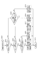
次に、本実施形態における制御の流れを説明する。図3は、本実施形態のデジタルビデオカメラ100におけるメイン制御処理を説明するためのフローチャートである。ステップS301は処理の開始を示している。
<Flow chart of main control processing>
Next, the flow of control in this embodiment will be described. FIG. 3 is a flowchart for explaining main control processing in the
ステップS302では、顔検出部116と人体検出部119において、撮影された画像から被写体の検出を行い、顔枠の表示設定を行う。詳細は図4を用いて後述する。
In step S <b> 302, the
ステップS303では、制御部114は、検出された被写体の領域に基づいて、焦点調節制御及び露出調節制御に用いる評価領域の設定を行う。
In step S303, the
ステップS304では、制御部114は焦点調節制御を実行し、設定されている焦点検出領域が合焦するようにフォーカスレンズを移動させる。詳細は図7〜図11を用いて後述する。
In step S304, the
ステップS305では、制御部114は露出調節制御を実行し、設定されている露出調整領域が適正露出になるように絞りを移動させる。詳細は図12〜図13を用いて後述する。そして、ステップS306に進み、処理を終了する。
In step S305, the
<顔枠表示設定処理のフローチャート>
次に、図4のフローチャートを用いて、図3のステップS302における顔枠表示設定処理について説明する。特に示さない限り、本処理は制御部114が制御する。
<Flowchart of face frame display setting process>
Next, the face frame display setting process in step S302 of FIG. 3 will be described using the flowchart of FIG. Unless otherwise indicated, this process is controlled by the
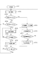
まず、ステップS401は処理の開始を示している。ステップS402では、顔検出部116は、取得された画像から前述の方法で顔検出処理を行い、ステップS403に遷移する。ステップS403では、人体検出部119は、取得された画像から前述の方法で人体検出処理を行い、ステップS404に遷移する。
First, step S401 indicates the start of processing. In step S402, the
ステップS404では、制御部114は、ステップS402の顔検出により顔領域が検出されたか否かの判定を行う。顔領域が検出されている場合は、ステップS405に遷移し、そうでない場合はステップS406に遷移する。
In step S404, the
ステップS405〜S410は、人体検出結果の有無に応じて、前述した顔枠表示の最小表示有効サイズの閾値を変更する処理である。ステップS405では、制御部114は、ステップS403で人体検出により人体領域が検出されたか否かの判定を行う。人体領域が検出されている場合はステップS408に遷移し、そうでない場合は、ステップS407に遷移する。
Steps S405 to S410 are processes for changing the threshold value of the minimum display effective size of the face frame display described above according to the presence or absence of the human body detection result. In step S405, the
ステップS408においては、顔領域及び人体領域が検出されている状態である。そのため、図2(C)で説明したように、顔枠表示の最小表示有効サイズ(表示有効サイズの閾値)を20ピクセルに設定する。なお、本実施形態では、この場合の最小表示有効サイズに本システムの顔検出の下限値を用いているが、上記下限値に限定されるものではなく、撮影被写体などに応じて変更しても良い。 In step S408, the face area and the human body area are detected. Therefore, as described with reference to FIG. 2C, the minimum display effective size (display effective size threshold) of the face frame display is set to 20 pixels. In this embodiment, the lower limit value of the face detection of the present system is used for the minimum display effective size in this case, but the lower limit value is not limited to the above lower limit value, and may be changed according to the subject to be photographed. good.
一方、ステップS407に進んだ場合、図2(B)で説明したように最小表示有効サイズを設定する。ステップS407で制御部114は、後述するステップS417で保持された前回の顔枠表示結果を参照し、今回顔検出された顔が、前回の検出に基づいて表示されている顔枠の顔と対応するか否かを判定する。前回の顔枠と対応すると判定した場合は、ステップS410に遷移し、そうでない場合(前回顔枠が表示されていない場合、または前回の顔枠と対応しない場合)はステップS409に遷移する。
On the other hand, when the process proceeds to step S407, the minimum display effective size is set as described with reference to FIG. In step S407, the
ステップS410では、人体検出結果が得られておらず、かつ、今回の顔検出結果と対応する前回の顔枠が存在しない状態である。そのため、制御部114は、顔枠表示の最小表示有効サイズを25ピクセルに設定する。つまり、本システムの顔検出の下限値より大きい値に設定する。なお、この閾値は25ピクセルに限定されるものではなく、顔検出のバラつきを考慮して設定してよい。本実施形態では、顔検出のバラつきを考慮した場合、5ピクセル程度のマージンを設定することにより顔枠表示のちらつきが減少するとして、顔検出の下限値より5ピクセル大きい25ピクセルと設定している。また、顔検出の信頼度によって顔枠表示の最小表示有効サイズを変更してもよい。具体的には、顔検出の信頼度が低い場合は、顔の検出サイズがばらつく可能性があるため、最小表示有効サイズをより大きい値に変更する。
In step S410, no human body detection result is obtained, and there is no previous face frame corresponding to the current face detection result. Therefore, the
ステップS409では、人体検出結果が得られておらず、かつ、今回の顔検出結果と対応する前回の顔枠が存在する状態である。そのため、顔枠表示の最小表示有効サイズ(表示有効サイズの閾値)を20ピクセルに設定する。つまり、ステップS410で設定される最小表示有効サイズより小さい値に設定する。なお、本実施形態では、この場合の最小表示有効サイズに本システムの顔検出の下限値を用いているが、上記下限値に限定されるものではなく、撮影被写体などに応じて変更しても良い。 In step S409, a human body detection result is not obtained, and there is a previous face frame corresponding to the current face detection result. For this reason, the minimum display effective size (display effective size threshold) for face frame display is set to 20 pixels. That is, a value smaller than the minimum display effective size set in step S410 is set. In this embodiment, the lower limit value of the face detection of the present system is used for the minimum display effective size in this case, but the lower limit value is not limited to the above lower limit value, and may be changed according to the subject to be photographed. good.
以上説明したように、ステップS405〜S410では、人体検出の有無に応じて顔枠の最小表示有効サイズを設定している。ステップS409またはS410において最小表示有効サイズが設定された後、ステップS414に遷移する。 As described above, in steps S405 to S410, the minimum display effective size of the face frame is set according to the presence or absence of human body detection. After the minimum display effective size is set in step S409 or S410, the process proceeds to step S414.
一方、ステップS406およびS411〜S413は、顔検出ができなかった場合に、人体検出結果に基づいて推定された顔領域を用いて顔枠表示する処理である。ステップS406で制御部114は、ステップS403の人体検出により人体領域が検出されたか否かの判定を行う。人体領域が検出されている場合はステップS411に遷移し、そうでない場合はステップS416に遷移する。
On the other hand, steps S406 and S411 to S413 are processing for displaying a face frame using a face region estimated based on the human body detection result when face detection cannot be performed. In step S406, the
ステップS411で人体検出部119は、検出した人体領域から前述の方法で顔領域を推定する処理を行い、ステップS412に遷移する。ステップS412で制御部114は、ステップS417で保持され記憶された前回の顔枠表示結果を参照する。そして、今回ステップS411で推定された顔が、前回の検出に基づいて表示されている顔枠の顔と対応するか否かを判定する。前回の顔枠と対応すると判定した場合は、ステップS413に遷移し、そうでない場合(前回顔枠が表示されていない場合、または前回の顔枠と対応しない場合)はステップS416に遷移する。
In step S411, the human
ステップS413で制御部114は、図2(C)で説明したように、顔枠表示の最小表示有効サイズを15ピクセルに設定する。なお、この閾値は本システムの人体検出に基づいて推定可能な顔領域の下限値を用いている。ただし、この場合の最小表示有効サイズは上記下限値に限定されるものではなく、撮影被写体などに応じて変更しても良い。
In step S413, the
ステップS413の処理が終了すると、ステップS414で制御部114は、人体検出結果から推定された顔領域のサイズが最小表示有効サイズ以上か否かを判定する。最小表示有効サイズ以上であればステップS415に遷移し、そうでない場合はステップS416に遷移する。
When the process in step S413 is completed, in step S414, the
ステップS415で制御部114は、表示すべき顔枠があるため、顔のサイズ、顔の位置データを表示部に送信し、顔枠を表示する。処理終了後、ステップS417に遷移する。
In step S415, since there is a face frame to be displayed, the
ステップS416で制御部114は、表示すべき顔枠がないため、顔枠表示は行わず、表示していた顔枠があれば解除する。処理終了後、ステップS417に遷移する。
In step S416, since there is no face frame to be displayed, the
ステップS417で制御部114は、ステップS415又はS416の顔枠表示結果を保持する。顔枠表示結果として、顔枠表示の有無と、表示の場合は顔枠の位置やサイズについての情報が記憶される。顔枠表示の結果は次回の処理に利用されるため、少なくとも次回の処理まで保持し記憶されることとする。処理終了後、ステップS418に遷移し、被写体検出処理を終了する。
In step S417, the
<評価領域設定処理のフローチャート>
次に、図5のフローチャートを用いて、図3のステップS303における評価領域設定処理の詳細を説明する。ステップS501は処理の開始を示している。
<Flowchart of evaluation area setting process>
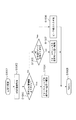
Next, details of the evaluation area setting process in step S303 of FIG. 3 will be described using the flowchart of FIG. Step S501 indicates the start of processing.
ステップS502では、制御部114は、ユーザーによって、AF制御及びAE制御を行いたい領域(評価領域)が指定されているか判定する。制御部114は、操作部121を通じてユーザーが評価領域を指定している場合にはステップS508に、そうでない場合はステップS503に、それぞれ処理を遷移させる。ユーザーが評価領域を指定する方法に特段の制限はなく、ライブビュー画像を表示している表示部109に対してタッチパネルで直接指定したり、方向キーを用いて領域を選択する方法などが一般的であるが、他の方法であってもよい。
In step S502, the
ステップS503では、制御部114は、図3のステップS302の処理によって顔枠表示がされているかを判定する。表示された顔枠がある場合にはステップS504に、表示された顔枠がない場合はステップS507に、それぞれ処理を遷移させる。
In step S503, the
ステップS504では、制御部114は、表示されている顔枠が複数か判定する。複数表示されている場合はステップS505に、1つのみ表示されている場合にはステップS506に、それぞれ処理を遷移させる。
In step S504, the
ステップS505では、制御部114は、複数表示されている顔枠の中から主被写体とする顔枠を決定し、主被写体として決定した顔枠に対して評価領域を設定する。主被写体の決定方法は、たとえば、顔領域の位置(例えば外接矩形の中心や、重心)が画面の中心に近いほど、またサイズが大きいほど大きなポイントを与え、最もポイントの高い顔枠に対応する顔領域を主被写体と決定する方法がある。なお、評価領域は顔枠に基づいて設定するが、顔枠と全く同一の領域に設定する必要はなく、サイズや形状、重心位置などが異なってもよい。
In step S505, the
図6は、顔枠表示の一例を示している。図6では、被写体603と被写体605が検出された場合を示しており、それぞれ顔枠604と顔枠606が表示されている。また、2つの被写体のうち上述のポイントが大きい被写体605を主被写体に設定している。図6では、顔枠を二重にすることにより主被写体であることを示しているが、例えば顔枠の色を変えるなどの他の方法で示してもよい。なお、顔枠の形状、個数は限定されない。
FIG. 6 shows an example of face frame display. FIG. 6 shows a case where a subject 603 and a subject 605 are detected, and a
表示されている顔枠が一つの場合、ステップS506で制御部114は、表示されている顔枠に対応する顔領域を主被写体と決定し、この顔領域に対して評価領域を設定する。
If there is only one face frame displayed, the
一方、顔枠が表示されていない場合、ステップS507で制御部114は、予め定められた位置およびサイズの評価領域を設定する。例えば図6の枠602に示すように、中央に矩形の領域を設定するなどがあるが、その形状や個数は特には限定しない。なお、この場合、ステップS502で述べたようなユーザーによる指定を促す表示をしてもよい。
On the other hand, when the face frame is not displayed, in step S507, the
ステップS502で評価領域の入力があった場合、ステップS508で制御部114は、指定された評価領域にステップS401で検出された顔領域またはステップS402で検出された人体領域が含まれているか否かを判定する。顔領域または人体領域が含まれている場合は処理をステップS509に遷移させ、含まれている顔領域または人体領域に基づいて評価領域を設定する。なお、人体領域に基づいて評価領域を設定する場合は、人体領域から推定された顔領域に基づいて評価領域を設定してもよい。
If an evaluation area is input in step S502, in step S508, the
一方、指定された評価領域に顔領域または人体領域が含まれていない場合、制御部114は処理をステップS510に遷移させ、指定された評価領域をそのまま設定する。
On the other hand, when the designated evaluation area does not include a face area or a human body area, the
<焦点調整制御(AF制御)のフローチャート>
次に、制御部114が図3のステップS304で行う焦点調整制御(AF制御)の詳細について、図7に示すフローチャートを用いて説明する。ステップS701は処理の開始を示している。
<Flowchart of focus adjustment control (AF control)>
Next, details of the focus adjustment control (AF control) performed by the
ステップS702で制御部114は、微小駆動動作を行わせる。微小駆動動作は、合焦判定や合焦方向の判定のため、フォーカスレンズを現在の位置を中心とした微小範囲内で駆動してAF評価値を取得する動作である。通常、微小駆動動作においては山登り駆動動作よりもフォーカスレンズの駆動範囲が小さい。微小駆動動作の詳細については図8を用いて後述する。
In step S702, the
ステップS703では、制御部114は、ステップS702での判定結果に応じて処理を分岐させる。ステップS702の微小駆動動作により合焦と判定された場合、制御部114は処理をステップS709へ進め、そうでなければ処理をステップS704へ進める。
In step S703, the
ステップS704では、制御部114は、ステップS702の微小駆動動作において合焦方向が判定できているかどうかにより処理をさらに分岐させる。すなわち、合焦方向が判定されていれば処理をステップS705へ進め、判定されていなければ処理をステップS702へ戻して微小駆動動作を継続する。
In step S704, the
ステップS705では、制御部114は、フォーカスレンズ駆動部111を制御し、AF評価値が大きくなる方向へ高速でフォーカスレンズを山登り駆動させる。山登り駆動動作の詳細については図10を用いて後述する。
In step S <b> 705, the
ステップS706では、制御部114は、ステップS705での山登り駆動動作において、AF評価値のピークを越えたか否かを判定する。ピークを越えたと判定された場合は処理をステップS707へ進め、そうでなければステップS705の山登り駆動動作を継続する。
In step S706, the
ステップS707では、制御部114は、フォーカスレンズ駆動部111を制御し、山登り駆動動作において得られた、AF評価値がピークとなるレンズ位置にフォーカスレンズ105を戻す。ステップS708で制御部114は、AF評価値がピークとなる位置にフォーカスレンズ105が戻ったか否かを判定する。そして、戻っていれば処理をステップS702へ戻して再び微小駆動動作を継続し、まだ戻っていない場合は処理をステップS707へ戻してフォーカスレンズ105の位置を戻す動作を継続する。
In step S707, the
次に、ステップS709からの合焦動作について説明する。ステップS709で制御部114は、AF信号処理回路113からのAF評価値を保持する。ステップS710では、制御部114は、最新のAF評価値をAF信号処理回路113から取得する。ステップS711で制御部114は、ステップS709で保持したAF評価値とステップS710で新たに取得したAF評価値とを比較し、AF評価値の変動が大きいか否か判定する。具体的には制御部114はAF評価値に所定値以上の差があれば変動が大きいと判定し、処理をステップS702へ戻して微小駆動動作を再開する。一方、AF評価値の変動が大きいと判定されなければ、ステップS712へ進み、制御部114はフォーカスレンズ駆動部111を制御してフォーカスレンズ105を停止させ、処理をステップS710へ戻す。
Next, the focusing operation from step S709 will be described. In step S709, the
<微小駆動動作のフローチャート>
次に、図7のステップS702で行う微小駆動動作について、図8に示すフローチャートを用いて説明する。ステップS801は処理の開始を示している。
<Flow chart of minute driving operation>
Next, the minute driving operation performed in step S702 of FIG. 7 will be described using the flowchart shown in FIG. Step S801 indicates the start of processing.
ステップS802で制御部114は、図3のステップS303で設定した評価領域(焦点検出領域)内の画素信号のみをAF信号処理回路113へ供給するようにAFゲート112を設定する。また、制御部114は、AF信号処理回路113がAF枠内部の画素信号に基づいて生成したAF評価値を取得する。
In step S802, the
ステップS803で制御部114は、ステップS802で取得したAF評価値が前回取得したAF評価値より大きいか否か判定する。そして、今回取得したAF評価値が前回取得したAF評価値以下であれば、制御部114はステップS805へ進み、フォーカスレンズ駆動部111を制御し、フォーカスレンズ105を前回と逆方向に所定量移動させる。一方、今回取得したAF評価値が前回取得したAF評価値よりも大きければ、制御部114はステップS804へ進み、フォーカスレンズ駆動部111を制御し、フォーカスレンズ105を前回と同じ方向にさらに所定量移動させる。
In step S803, the
ステップS806では、制御部114は、ステップS803におけるAF評価値の大小関係の判定結果、あるいはフォーカスレンズ105の駆動方向が所定回数連続して変化していないか、つまり合焦方向と判断される方向が所定回数(N回)同一か否か調べる。もし所定回数連続して合焦方向と判断される方向が変化していなければ、ステップS807において制御部114は、方向判定できたものと判定し、ステップS810に進んで微小駆動動作を終了する。
In step S806, the
一方、所定回数連続して合焦方向と判断される方向が同一でない場合、ステップS808において制御部114は、フォーカスレンズ105の位置が同一範囲内で所定回数往復しているかどうかを判定する。この判定は、フォーカスレンズ105の位置が、所定時間所定範囲内にあるか否かの判定であっても良い。いずれかの条件が満たされていることが判定できた場合、制御部114はステップS809で合焦判定できたものとして、ステップS810に進んで微小駆動動作を終了する。また、ステップS810において、いずれの条件も満たされていない場合は、方向判定も合焦判定もできていないものとして微小駆動動作を終了する。
On the other hand, if the direction determined to be the in-focus direction is not the same for a predetermined number of times, in step S808, the
図9は、微小駆動動作中のフォーカスレンズ105の位置変化の例を示す図であり、横軸が時間、縦軸がフォーカスレンズ105の位置を示している。図9において、期間Aに撮像素子106に蓄積された電荷に基づいて、CDS/AGC回路107が生成した信号からAF評価値が生成される。CDS/AGC回路107が生成した信号のうち、焦点検出領域に対応する信号からAF信号処理回路113AF評価値AFAを生成し、時刻TAで制御部114により取得される。その後、微小駆動動作により、フォーカスレンズ105が矢印aの方向に所定量移動され、期間Bに撮像素子106で蓄積された電荷信号から生成されたAF評価値AFBが、時刻TBで制御部114により取得される。
FIG. 9 is a diagram illustrating an example of a change in the position of the
そして、制御部114は、AF評価値AFAとAFBを比較し、AFA<AFBであればそのまま順方向(前回と同じ方向、即ち矢印aの方向)にフォーカスレンズ105を所定量移動させる。一方、AFA>AFBであれば、逆方向(前回と逆の方向、即ち矢印bの方向)にフォーカスレンズ105を所定量移動させる。
Then, the
なお、微小駆動動作におけるS804及びS805におけるフォーカスレンズ105の一回の移動量は、画像を表示部109等で表示した際に焦点状態の変化がユーザーに判別できないような量とすることが好ましい。具体的には、移動後の位置が焦点深度内にあるような移動量とすることが好ましい。
Note that it is preferable that the amount of movement of the
<山登り駆動動作のフローチャート>
次に、図7のS705で行う山登り駆動動作について、図10に示すフローチャートを用いて説明する。ステップS1001は処理の開始を示している。
<Flow chart of hill-climbing driving operation>
Next, the hill-climbing driving operation performed in S705 of FIG. 7 will be described using the flowchart shown in FIG. Step S1001 indicates the start of processing.
山登り駆動動作においても、微小駆動動作と同様、制御部114はまずステップS1002でAF評価値を取得する。次に、ステップS1003で制御部114は、前回取得したAF評価値と今回取得したAF評価値のサイズを比較し、処理を分岐させる。
Also in the hill-climbing driving operation, similarly to the minute driving operation, the
今回取得したAF評価値が前回取得したAF評価値よりも大きければ、ステップS1004に進む。ステップS1004では、制御部114はフォーカスレンズ駆動部111を制御し、フォーカスレンズ105を前回と同じ方向(順方向)に所定の速度で移動させ、処理を終了する。
If the AF evaluation value acquired this time is larger than the AF evaluation value acquired last time, the process proceeds to step S1004. In step S1004, the
一方、今回取得したAF評価値が前回取得したAF評価値以下であれば、ステップS1005に進む。ステップS1005で制御部114は、AF評価値がピークを越えて減少したかどうか判定する。そして、AF評価値がピークを越えて減少したと判定された場合、S1006へ進み、制御部114はピークを越えたと判定して処理を終了する。ステップS1005でAF評価値がピークを越えて減少したと判定されなかった場合、ステップS1007へ進む。ステップS1007では、制御部114は、フォーカスレンズ駆動部111を制御し、フォーカスレンズ105を前回と逆方向に所定の速度で移動させ、処理を終了する。
On the other hand, if the currently acquired AF evaluation value is less than or equal to the previously acquired AF evaluation value, the process advances to step S1005. In step S1005, the
図11は、山登り駆動動作中のAF評価値のサイズとフォーカスレンズ105の駆動動作の例を示す図である。図11において、山登り駆動の開始位置から図中右方向にフォーカスレンズ105を駆動した場合、矢印Aで示すように、AF評価値がピークを越えて減少していることが検出される。この場合、合焦点を通り過ぎたものとして山登り駆動動作を終了し、AF評価値のピークが得られた位置にフォーカスレンズ105を戻し(図7のステップS707及びS708)、微小駆動動作に移行する(ステップS702)。
FIG. 11 is a diagram illustrating an example of the size of the AF evaluation value and the driving operation of the
一方、山登り駆動の開始位置から図中左方向にフォーカスレンズ105を駆動した場合、矢印Bで示すように、AF評価値がピークを越えることなく減少していることが検出される。この場合、フォーカスレンズ105の移動方向を間違えたものと判断して、逆方向に山登り駆動動作を継続する。なお、山登り駆動において、フォーカスレンズ105の一定時間あたりの移動量は、上述した微小駆動動作時よりも大きい。
On the other hand, when the
このように、制御部114は、再起動(微小駆動からのやり直し)要否判定→微小駆動→山登り駆動→微小駆動→再起動判定を繰り返しながら、AF評価値がピークとなる位置にフォーカスレンズ105を移動させるAF制御動作を行う。
As described above, the
<露出調節制御のフローチャート>
次に、制御部114が実行する露出調節(AE)制御の概要について説明する。図12は、本実施形態における露出調節制御を示すフローチャートである。ステップS1201は処理の開始を示している。
<Flow chart of exposure adjustment control>
Next, an outline of exposure adjustment (AE) control executed by the
まずステップS1202で制御部114は、輝度情報検波・演算回路118より、露出制御に用いる評価値としての輝度情報を取得する。ここでの輝度情報は、図3のステップS303で位置とサイズを設定された評価領域(測光枠)から取得される。
First, in step S <b> 1202, the
ステップS1202で制御部114は、露出制御により輝度調節を行う。その後、ステップS1202へ戻り、この処理を繰り返す。
In step S1202, the
次に、ステップS1202における露出制御について説明する。CDS/AGC回路107より出力された輝度信号は、輝度情報検波・演算回路118を経て、制御部114に取り込まれる。制御部114は、輝度情報検波・演算回路118の出力レベルが所定の範囲内に入るように、絞り駆動部117を制御する。絞り駆動制御系は、駆動電流を制御して、絞り103の開口量を可変する絞り制御により露出制御を行う。制御部114は、絞り103による露出制御同様、制御部114に取り込まれた輝度情報検波・演算回路118の出力レベルが所定の範囲内になるように、CDS/AGC回路107のゲインのレベルを制御する。このような閉ループ制御によって、露出制御系が構成されている。
Next, exposure control in step S1202 will be described. The luminance signal output from the CDS /
続いて図13において、明るさに応じた露出制御を説明する。図13は、横軸は被写体照度、縦軸は絞り、ゲインの各露出制御手段の設定値である。同図から明らかなように、各露出制御手段は被写体照度に応じてA,Bと2つの領域に分割されている。すなわち、被写体照度に応じて2種類の露出制御手段を組み合わせることにより、露出の動作制御を行っている。領域Aにおいては、AGC回路のゲインも0dBで固定されており、絞りの開口量のみで露出が制御される。領域Bにおいては、前記絞りが開放で固定され、AGC回路のみで露出が制御される。なお、本実施例では、露出制御にあたり、絞り部材とAGC回路を用いたが、新たにNDやシャッター速度を加えた露出制御系により、精度の高い露出制御を行っても良い。 Subsequently, referring to FIG. 13, exposure control according to brightness will be described. In FIG. 13, the horizontal axis represents subject illuminance, and the vertical axis represents the setting values of the aperture and gain exposure control means. As is apparent from the figure, each exposure control means is divided into two areas A and B according to the subject illuminance. That is, exposure operation control is performed by combining two types of exposure control means in accordance with subject illumination. In region A, the gain of the AGC circuit is also fixed at 0 dB, and exposure is controlled only by the aperture amount of the diaphragm. In region B, the aperture is fixed at the open position, and exposure is controlled only by the AGC circuit. In this embodiment, the aperture member and the AGC circuit are used for exposure control. However, highly accurate exposure control may be performed by an exposure control system to which ND or shutter speed is newly added.
このように、本実施形態で制御部114は、絞り駆動による露出制御系と、AGC回路による露出制御系の2種類の制御系を持ち、取り込まれた輝度情報検波・演算回路118の出力レベルが所定の範囲内に収まるように、露出制御を繰り返し行っている。
As described above, in this embodiment, the
以上説明したように、本実施形態では、顔検出及び人体検出の検出状況に応じて顔枠表示の有効サイズを設定することにより、顔枠を安定して表示することが可能になる。また、上記の顔枠に基づいて、AF制御やAE制御に用いる評価値を取得する評価領域を設定することにより、安定したAF制御やAE制御を行うことが可能になる。 As described above, in this embodiment, the face frame can be stably displayed by setting the effective size of the face frame display according to the detection status of face detection and human body detection. Further, by setting an evaluation area for acquiring an evaluation value used for AF control or AE control based on the face frame, stable AF control or AE control can be performed.
(その他の実施形態)
本発明は、以下の処理を実行することによっても実現される。即ち、上述した実施形態の機能を実現するソフトウェア(プログラム)を、ネットワーク又は各種記憶媒体を介してシステム或いは装置に供給し、そのシステム或いは装置のコンピュータ(またはCPUやMPU等)がプログラムを読み出して実行する処理である。
(Other embodiments)
The present invention is also realized by executing the following processing. That is, software (program) that realizes the functions of the above-described embodiments is supplied to a system or apparatus via a network or various storage media, and a computer (or CPU, MPU, or the like) of the system or apparatus reads the program. It is a process to be executed.
100 デジタルビデオカメラ
114 制御部
116 顔検出部
119 人体検出部
DESCRIPTION OF
Claims (21)
前記第1の検出対象の領域を推定可能な第2の検出対象の領域を画像から検出する第2の検出手段と、
所定条件を満たす場合に、前記第1の検出対象の領域を示す所定の形態の表示を行うように制御する制御手段とを有し、
前記制御手段は、前記所定の形態の表示が行われていない状態において前記第1の検出手段により前記第1の検出対象の領域が検出された際に、さらに前記第2の検出手段により前記第2の検出対象の領域が検出されたか否かに基づいて、前記所定条件を変更することを特徴とする被写体検出装置。 First detection means for detecting a first detection target region from the image;
Second detection means for detecting from the image a second detection target region capable of estimating the first detection target region;
Control means for controlling to perform display in a predetermined form indicating the first detection target area when a predetermined condition is satisfied;
The control means further includes the second detection means when the first detection area is detected by the first detection means in a state where the display of the predetermined form is not performed. An object detection apparatus, wherein the predetermined condition is changed based on whether or not two detection target areas are detected.
前記設定手段は、前記第1の検出対象の領域に基づいて、前記評価領域を設定することを特徴とする請求項1乃至14のいずれか1項に記載の被写体検出装置。 Having setting means for setting an evaluation region for acquiring a signal used for predetermined control;
The subject detection apparatus according to claim 1, wherein the setting unit sets the evaluation area based on the first detection target area.
被写体像を光電変換して画像を生成する撮像手段を有することを特徴とする撮像装置。 A subject detection device according to any one of claims 1 to 17,
An image pickup apparatus comprising image pickup means for photoelectrically converting a subject image to generate an image.
画像から第1の検出対象の領域を検出する第1の検出ステップと、
前記第1の検出対象の領域を推定可能な第2の検出対象の領域を画像から検出する第2の検出ステップと、
所定条件を満たす場合に、前記第1の検出対象の領域を示す所定の形態の表示を行うように制御する制御ステップとを有し、
前記制御ステップにおいて、前記所定の形態の表示が行われていない状態において前記第1の検出ステップにより前記第1の検出対象の領域が検出された際に、さらに前記第2の検出ステップにより前記第2の検出対象の領域が検出されたか否かに基づいて、前記所定条件を変更することを特徴とする被写体検出装置の制御方法。 A method for controlling a subject detection device, comprising:
A first detection step of detecting a first detection target region from the image;
A second detection step of detecting from the image a second detection target region capable of estimating the first detection target region;
A control step for controlling to perform display in a predetermined form indicating the first detection target area when a predetermined condition is satisfied,
In the control step, when the first detection target region is detected by the first detection step in a state where the display of the predetermined form is not performed, the second detection step further performs the first detection. A control method for a subject detection apparatus, wherein the predetermined condition is changed based on whether or not two detection target areas are detected.
Priority Applications (2)
| Application Number | Priority Date | Filing Date | Title |
|---|---|---|---|
| JP2013128286A JP6184189B2 (en) | 2013-06-19 | 2013-06-19 | SUBJECT DETECTING DEVICE AND ITS CONTROL METHOD, IMAGING DEVICE, SUBJECT DETECTING DEVICE CONTROL PROGRAM, AND STORAGE MEDIUM |
| US14/307,384 US9160922B2 (en) | 2013-06-19 | 2014-06-17 | Subject detection device and control method for the same, imaging apparatus, and storage medium |
Applications Claiming Priority (1)
| Application Number | Priority Date | Filing Date | Title |
|---|---|---|---|
| JP2013128286A JP6184189B2 (en) | 2013-06-19 | 2013-06-19 | SUBJECT DETECTING DEVICE AND ITS CONTROL METHOD, IMAGING DEVICE, SUBJECT DETECTING DEVICE CONTROL PROGRAM, AND STORAGE MEDIUM |
Publications (3)
| Publication Number | Publication Date |
|---|---|
| JP2015005799A JP2015005799A (en) | 2015-01-08 |
| JP2015005799A5 JP2015005799A5 (en) | 2016-07-28 |
| JP6184189B2 true JP6184189B2 (en) | 2017-08-23 |
Family
ID=52110980
Family Applications (1)
| Application Number | Title | Priority Date | Filing Date |
|---|---|---|---|
| JP2013128286A Expired - Fee Related JP6184189B2 (en) | 2013-06-19 | 2013-06-19 | SUBJECT DETECTING DEVICE AND ITS CONTROL METHOD, IMAGING DEVICE, SUBJECT DETECTING DEVICE CONTROL PROGRAM, AND STORAGE MEDIUM |
Country Status (2)
| Country | Link |
|---|---|
| US (1) | US9160922B2 (en) |
| JP (1) | JP6184189B2 (en) |
Families Citing this family (13)
| Publication number | Priority date | Publication date | Assignee | Title |
|---|---|---|---|---|
| EP2713307B1 (en) * | 2012-09-28 | 2018-05-16 | Accenture Global Services Limited | Liveness detection |
| JP2014126710A (en) * | 2012-12-26 | 2014-07-07 | Canon Inc | Automatic focus detection device, control method therefor, and image capturing device |
| JP6700661B2 (en) * | 2015-01-30 | 2020-05-27 | キヤノン株式会社 | Image processing apparatus, image processing method, and image processing system |
| JP2020522002A (en) * | 2017-06-02 | 2020-07-27 | エスゼット ディージェイアイ テクノロジー カンパニー リミテッドSz Dji Technology Co.,Ltd | Method and system for recognizing, tracking, and focusing a moving target |
| CN107360366B (en) * | 2017-06-30 | 2020-05-12 | Oppo广东移动通信有限公司 | Photographing method and device, storage medium and electronic equipment |
| US20200209980A1 (en) * | 2018-12-28 | 2020-07-02 | United States Of America As Represented By The Secretary Of The Navy | Laser Pointer Screen Control |
| USD963407S1 (en) | 2019-06-24 | 2022-09-13 | Accenture Global Solutions Limited | Beverage dispensing machine |
| US10726246B1 (en) | 2019-06-24 | 2020-07-28 | Accenture Global Solutions Limited | Automated vending machine with customer and identification authentication |
| WO2021145286A1 (en) * | 2020-01-14 | 2021-07-22 | 三菱電機株式会社 | Signal processing device |
| EP3869395A1 (en) | 2020-02-21 | 2021-08-25 | Accenture Global Solutions Limited | Identity and liveness verification |
| CN111783644B (en) * | 2020-06-30 | 2023-07-14 | 百度在线网络技术(北京)有限公司 | Detection method, detection device, detection equipment and computer storage medium |
| JP2022043633A (en) * | 2020-09-04 | 2022-03-16 | キヤノン株式会社 | Information processing apparatus, method, program, and storage medium |
| JP2022045757A (en) * | 2020-09-09 | 2022-03-22 | キヤノン株式会社 | Imaging control device and control method of the same |
Family Cites Families (12)
| Publication number | Priority date | Publication date | Assignee | Title |
|---|---|---|---|---|
| JP2002251380A (en) | 2001-02-22 | 2002-09-06 | Omron Corp | User collation system |
| JP5055018B2 (en) * | 2006-06-14 | 2012-10-24 | キヤノン株式会社 | Image processing apparatus, imaging apparatus, and control method for image processing apparatus |
| JP4218712B2 (en) | 2006-08-04 | 2009-02-04 | ソニー株式会社 | Face detection device, imaging device, and face detection method |
| JP4725802B2 (en) * | 2006-12-27 | 2011-07-13 | 富士フイルム株式会社 | Imaging apparatus, focusing method, and focusing program |
| JP2009211311A (en) | 2008-03-03 | 2009-09-17 | Canon Inc | Image processing apparatus and method |
| JP2010226558A (en) * | 2009-03-25 | 2010-10-07 | Sony Corp | Apparatus, method, and program for processing image |
| JP5485781B2 (en) * | 2010-05-10 | 2014-05-07 | 株式会社ザクティ | Electronic camera |
| JP2012103979A (en) * | 2010-11-11 | 2012-05-31 | Sanyo Electric Co Ltd | Image processing apparatus |
| JP5814557B2 (en) * | 2011-02-07 | 2015-11-17 | キヤノン株式会社 | Image display control device, imaging device, display control method, and control program |
| US8842213B2 (en) * | 2011-04-18 | 2014-09-23 | Panasonic Corporation | Image capture device, image capture device focus control method, and integrated circuit |
| US8620088B2 (en) * | 2011-08-31 | 2013-12-31 | The Nielsen Company (Us), Llc | Methods and apparatus to count people in images |
| JP5978639B2 (en) * | 2012-02-06 | 2016-08-24 | ソニー株式会社 | Image processing apparatus, image processing method, program, and recording medium |
-
2013
- 2013-06-19 JP JP2013128286A patent/JP6184189B2/en not_active Expired - Fee Related
-
2014
- 2014-06-17 US US14/307,384 patent/US9160922B2/en not_active Expired - Fee Related
Also Published As
| Publication number | Publication date |
|---|---|
| US9160922B2 (en) | 2015-10-13 |
| US20140376813A1 (en) | 2014-12-25 |
| JP2015005799A (en) | 2015-01-08 |
Similar Documents
| Publication | Publication Date | Title |
|---|---|---|
| JP6184189B2 (en) | SUBJECT DETECTING DEVICE AND ITS CONTROL METHOD, IMAGING DEVICE, SUBJECT DETECTING DEVICE CONTROL PROGRAM, AND STORAGE MEDIUM | |
| US20200280681A1 (en) | Zoom control device, control method of zoom control device, and recording medium | |
| US8831282B2 (en) | Imaging device including a face detector | |
| JP5409189B2 (en) | Imaging apparatus and control method thereof | |
| US9253395B2 (en) | Automatic focus detection apparatus, control method for the same, and image pickup apparatus | |
| JP5335302B2 (en) | Focus detection apparatus and control method thereof | |
| US9317748B2 (en) | Tracking apparatus | |
| US20160191811A1 (en) | Zoom control device, imaging apparatus, control method of zoom control device, and recording medium | |
| JP5991755B2 (en) | Automatic focus detection apparatus and control method thereof | |
| JP2006201282A (en) | Digital camera | |
| US8648960B2 (en) | Digital photographing apparatus and control method thereof | |
| KR20110032250A (en) | Method for auto focusing, medium for recording the method and apparatus applying the method | |
| JPWO2017037978A1 (en) | DETECTING DEVICE, DETECTING METHOD, DETECTING PROGRAM, AND IMAGING DEVICE | |
| JP2009198574A (en) | Focusing apparatus and method for controlling the same | |
| JP5335408B2 (en) | Focus adjustment apparatus and method | |
| JP2007133301A (en) | Autofocus camera | |
| JP5075110B2 (en) | Focus adjustment apparatus and method | |
| JP5873336B2 (en) | Focus adjustment device | |
| JP2014106411A (en) | Automatic focus adjustment device and automatic focus adjustment method | |
| JP2010152162A (en) | Automatic focus detection device and method for controlling the same | |
| JP4981758B2 (en) | Focus adjustment apparatus and method | |
| JP7342883B2 (en) | Imaging control device, imaging device, imaging control method | |
| JP5017195B2 (en) | Focus adjustment apparatus and method | |
| JP5932340B2 (en) | Focus adjustment device | |
| JP5621027B2 (en) | Imaging apparatus and control method thereof |
Legal Events
| Date | Code | Title | Description |
|---|---|---|---|
| A521 | Request for written amendment filed |
Free format text: JAPANESE INTERMEDIATE CODE: A523 Effective date: 20160609 |
|
| A621 | Written request for application examination |
Free format text: JAPANESE INTERMEDIATE CODE: A621 Effective date: 20160609 |
|
| A977 | Report on retrieval |
Free format text: JAPANESE INTERMEDIATE CODE: A971007 Effective date: 20170330 |
|
| A131 | Notification of reasons for refusal |
Free format text: JAPANESE INTERMEDIATE CODE: A131 Effective date: 20170411 |
|
| A521 | Request for written amendment filed |
Free format text: JAPANESE INTERMEDIATE CODE: A523 Effective date: 20170609 |
|
| TRDD | Decision of grant or rejection written | ||
| A01 | Written decision to grant a patent or to grant a registration (utility model) |
Free format text: JAPANESE INTERMEDIATE CODE: A01 Effective date: 20170627 |
|
| A61 | First payment of annual fees (during grant procedure) |
Free format text: JAPANESE INTERMEDIATE CODE: A61 Effective date: 20170725 |
|
| R151 | Written notification of patent or utility model registration |
Ref document number: 6184189 Country of ref document: JP Free format text: JAPANESE INTERMEDIATE CODE: R151 |
|
| LAPS | Cancellation because of no payment of annual fees |