JP4723099B2 - Movable gripper unit, gripping device, and printed product gripping method - Google Patents
Movable gripper unit, gripping device, and printed product gripping method Download PDFInfo
- Publication number
- JP4723099B2 JP4723099B2 JP2001012994A JP2001012994A JP4723099B2 JP 4723099 B2 JP4723099 B2 JP 4723099B2 JP 2001012994 A JP2001012994 A JP 2001012994A JP 2001012994 A JP2001012994 A JP 2001012994A JP 4723099 B2 JP4723099 B2 JP 4723099B2
- Authority
- JP
- Japan
- Prior art keywords
- arm
- gripper
- gripping
- printed product
- unit
- Prior art date
- Legal status (The legal status is an assumption and is not a legal conclusion. Google has not performed a legal analysis and makes no representation as to the accuracy of the status listed.)
- Expired - Fee Related
Links
Images


Classifications
-
- B—PERFORMING OPERATIONS; TRANSPORTING
- B65—CONVEYING; PACKING; STORING; HANDLING THIN OR FILAMENTARY MATERIAL
- B65G—TRANSPORT OR STORAGE DEVICES, e.g. CONVEYORS FOR LOADING OR TIPPING, SHOP CONVEYOR SYSTEMS OR PNEUMATIC TUBE CONVEYORS
- B65G17/00—Conveyors having an endless traction element, e.g. a chain, transmitting movement to a continuous or substantially-continuous load-carrying surface or to a series of individual load-carriers; Endless-chain conveyors in which the chains form the load-carrying surface
- B65G17/30—Details; Auxiliary devices
- B65G17/32—Individual load-carriers
- B65G17/323—Grippers, e.g. suction or magnetic
-
- B—PERFORMING OPERATIONS; TRANSPORTING
- B65—CONVEYING; PACKING; STORING; HANDLING THIN OR FILAMENTARY MATERIAL
- B65H—HANDLING THIN OR FILAMENTARY MATERIAL, e.g. SHEETS, WEBS, CABLES
- B65H29/00—Delivering or advancing articles from machines; Advancing articles to or into piles
- B65H29/003—Delivering or advancing articles from machines; Advancing articles to or into piles by grippers
-
- B—PERFORMING OPERATIONS; TRANSPORTING
- B65—CONVEYING; PACKING; STORING; HANDLING THIN OR FILAMENTARY MATERIAL
- B65H—HANDLING THIN OR FILAMENTARY MATERIAL, e.g. SHEETS, WEBS, CABLES
- B65H2403/00—Power transmission; Driving means
- B65H2403/50—Driving mechanisms
- B65H2403/51—Cam mechanisms
- B65H2403/513—Cam mechanisms involving elongated cam, i.e. parallel to linear transport path
-
- B—PERFORMING OPERATIONS; TRANSPORTING
- B65—CONVEYING; PACKING; STORING; HANDLING THIN OR FILAMENTARY MATERIAL
- B65H—HANDLING THIN OR FILAMENTARY MATERIAL, e.g. SHEETS, WEBS, CABLES
- B65H2403/00—Power transmission; Driving means
- B65H2403/50—Driving mechanisms
- B65H2403/53—Articulated mechanisms
- B65H2403/531—Planar mechanisms
- B65H2403/5311—Parallelogram mechanisms
-
- B—PERFORMING OPERATIONS; TRANSPORTING
- B65—CONVEYING; PACKING; STORING; HANDLING THIN OR FILAMENTARY MATERIAL
- B65H—HANDLING THIN OR FILAMENTARY MATERIAL, e.g. SHEETS, WEBS, CABLES
- B65H2403/00—Power transmission; Driving means
- B65H2403/50—Driving mechanisms
- B65H2403/53—Articulated mechanisms
- B65H2403/533—Slotted link mechanism
- B65H2403/5333—Slotted link mechanism with oscillating slotted link
Abstract
Description
【0001】
【発明の属する技術分野】
本発明は一般的に印刷機に関し、特に、印刷製品の搬送装置および搬送方法に関する。
【0002】
【従来の技術】
ウエブ印刷機は、紙のような材料の連続するウエブを印刷する。この連続するウエブは、この後、ブックブロックを形成するために裁断ユニットで裁断される。これらのブックブロックは、例えば新聞の折り丁であってもよい。これらのブックブロックを搬送または処理するために、すなわち例えば仕上げ裁ちする操作を行うために、走行路に沿って移動可能なくわえづめを用いてこのブックブロックをしっかりと把持することが望ましい場合が少なくない。
【0003】
米国特許出願第5、727、783号は印刷製品のシートを分配する装置を開示している。この場合、複数のくわえづめが所定のピッチで走行路に沿って移動し、印刷製品を把持する。
【0004】
【発明が解決しようとする課題】
しかしながら、これらの印刷製品は、そのそれぞれのくわえづめに対して固定され、減速されるために減速装置に転送されなければならない。この転送は印刷製品を損傷する原因となることがある。
【0005】
本発明の目的は、印刷製品を保持および搬送、それによって、印刷製品がくわえづめに対して相対的に移動する装置および方法を提供することにある。本発明の付加的なまたは他の目的は、印刷製品が損傷するおそれを低減することにある。
【0006】
【課題を解決するための手段】
本発明は、ハウジングと、印刷製品を把持する第1のくわえづめアームおよび第2のくわえづめアームを含み、この第1および第2のくわえづめアームは、ハウジングに対して摺動するくわえづめユニットを提供する。ハウジングは走行路に沿って移動可能である。
【0007】
第1および第2のくわえづめアームはハウジングに対して摺動するので、くわえづめアームによって保持される印刷製品の速度は走行路の速度に対して変化する。この速度の変化は、印刷製品がしっかりとくわえづめアームによって保持されている間にも生じる。
【0008】
第1のくわえづめアームは第1のバーに取り付けられていることが好ましく、第2のくわえづめアームは第2のバーに取り付けられていることが好ましい。各バーはその各端が、すなわち、逆U字状が好ましいハウジングの側部に形成された溝内を摺動可能なキャリッジに取り付けられている。第1のバーは、その端がキャリッジに対して固定されることが好ましく、第2のバーは、印刷製品を把持する第2のくわえづめアームを回転しないように固定された第1のくわえづめアームに向かって動かすように回転できることが好ましい。
【0009】
回転可能な第2のバーは、第2のくわえづめアームが開いた位置に押しやられるようにその端がキャリッジに対してばねで付勢されていることが好ましい。
【0010】
回転可能な第2のバーに取り付けられた作動レバーと、キャリッジの1つは、第2のくわえづめアームが印刷製品を把持するように第2のバーをばね力に抗して動かすことができる。さらに、カムフォロワが、レバーを閉じた位置に保持するように中心線を越えた状態でロックできる。それから、ラッチはレバーを閉じた位置にロックでき、この結果、第2のバーは開いた位置へ回転して戻ることができない。
【0011】
ラッチが一旦ロック状態を解除されると、第2のバーのばね付勢力が第2のくわえづめアームを開いた位置に付勢するので、印刷製品は解放され得る。
【0012】
また、カムフォロワを備え、このカムフォロワを、2つのアームを有するV字状のヒンジに接続してもよい。一方のアームはハウジングの側に接続され、他方のアームは摺動可能なキャリッジに接続される。カムフォロワが追従するカムは、摺動可能なキャリッジがハウジングに対して溝内で移動できるようにV字状のヒンジを平坦化できる。このヒンジは、中心線を越えた状態でロックしてもよい。くわえづめユニットの各側部は、カムフォロワ/ヒンジ構造を有していることが好ましい。
【0013】
本発明は、走行路と、この走行路内を走行する複数のくわえづめユニットとを有し、各くわえづめユニットは、ハウジングと、印刷製品を把持する第1のくわえづめアームおよび第2のくわえづめアームとを備えており、第1および第2のくわえづめアームはハウジング内に摺動可能に支持されている把持装置を提供する。
【0014】
把持装置は、さらに、くわえづめユニットを好ましくは一定の速度で駆動するチェーン駆動装置を備えてもよい。印刷製品が保持されている間に印刷製品の速度を変えるように、ハウジングに対して各くわえづめユニットのくわえづめアームを摺動させるカムを備えてもよい。カムは、ハウジング内でくわえづめアームを支持する摺動可能なキャリッジに接続されたカムフォロワと相互に作用してもよい。
【0015】
本発明は、さらに、くわえづめユニットで印刷製品を把持すること、および、印刷製品が保持されたままの状態にある間にこの印刷製品をくわえづめユニットに対して動かすことを含む、印刷製品を把持する方法をも提供するものである。印刷製品は2つのくわえづめアームによって保持され、それから、この移動するステップの間ハウジング内の溝内を摺動することが好ましい。摺動動作を行うために、カム相互作用を用いると有利である。
【0016】
第2のくわえづめアームは回転可能であることが好ましく、また、本方法は、閉じた位置で第2のアームをラッチによってロックすること、および、印刷製品を解放するようにラッチを解除することを含んでいることが好ましい。
【0017】
【発明の実施の形態】
以下、本発明の2つの好適な実施形態を図面を参照して説明する。
【0018】
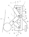
図1は、走行路上、すなわち例えば定速チェーンが通る経路2上を走行するくわえづめユニット1を示している。くわえづめユニット1は、第1の側部10と第2の側部110(図4に図示)とを有するハウジング3を備えている。したがってハウジング3は例えば逆U字状であってもよい。第1の側部10は、内部で、キャリッジ14が前後に摺動可能な溝12を有している。くわえづめユニット1は、印刷製品5を把持する第1のくわえづめアーム20と第2のくわえづめアーム30とを備えている。第1のくわえづめアーム20は、例えば、ハウジング3の第2の側部110にある溝内の他のキャリッジに固定して接続されたバー22に取り付けられることによって、キャリッジ14に対して固定されている。
【0019】
第2のくわえづめアーム30はキャリッジ14内で回転可能なバー32に固定して取り付けられている。第2のくわえづめアーム30はキャリッジ14に対して矢印34の方向に回転するようにばね付勢され、この結果、第2のくわえづめアーム30は、図示するような開位置に押し込まれている。作動レバー36が、バー32に固定して取り付けられている。V字状のヒンジ40の一方の第1のアーム42はバー32に回転可能に取り付けられ、かつ、ピン45によってヒンジ40の第2のアーム44に回転可能に取り付けられている。この第2のアームは、ピン48によってハウジング3に回転可能に取り付けられている。カムフォロワ46がアーム42に固定して取り付けられている。
【0020】
カムフォロワ46は、ヒンジ40を強制的に開かせ、キャリッジ14が溝12内で前方へ摺動させるために、カム50に追従させることができる。図2は、溝12内を矢印6の方向である前方へ摺動させられるキャリッジ14を示している。作動レバー36が作動ピン37と相互作用すると、作動レバー36は矢印34の方向に、すなわち図1中で矢印34で表されるばね力に抗した力で押される。したがって、バー32に固定して取り付けられた作動するアーム36は、バー32を反時計回りに回転させる。
【0021】
第2のくわえづめアーム30がバー32に固定して取り付けられているので、この第2のくわえづめアーム30は、矢印39によって示されるように下方に回転する。
【0022】
図3に示すように、カム50は、カムフォロワ46を下方に向かって押しており、この結果、ヒンジ40は中心線60を超えた状態でロックされる。キャリッジ14は、溝12内の最前方位置に移動させられる。キャリッジ14の端部は、溝12の内側でもよく、また、ハウジング3を超えて延びてもよいが、キャリッジ14は溝12の端と相互作用する段部15(図2を参照のこと)によって、さらに前方へ移動しないようになっている。
【0023】
作動レバー36は、バー32および第2のくわえづめアーム30が、印刷製品5を回転して保持するように、図3に示す位置では反時計回りに動く。
【0024】
図4は図3に示したくわえづめユニット1の斜視図を示している。ハウジング3は、概略的に示す走行路2上を走行可能な第1の側部10、第2の側部110、および上面部11を備えている。第2の側部110は、キャリッジが摺動可能な溝112を有している。くわえづめユニット1の第2の側部110の近傍にも、第1のアーム142と第2のアーム144とを有するV字状の第1のヒンジ140上に支持されるカムフォロワ146が備えられている。
【0025】
図5は、図3で示すくわえづめユニット1の側とは反対の側を示している。第2の第1のヒンジ140は、カムフォロワ146が追従する第2のカム150によって、中心線を越えてロックされる。第1のヒンジ140のアーム144はピン148およびピン145に回転可能に接続されている。第1のヒンジ140のアーム142はピン145およびバー32に接続されている。キャリッジ114は、カム150によって下方に押されるカムフォロワ146の動作によって、溝112内を前方に摺動する。
【0026】
ラッチ136が、ピン137のまわりを時計回りに作動するように、ピン137によってキャリッジ114に回転可能に取り付けられている。この時計回り方向の力は、例えば、ばねを用いて作用させるようにしてもよく、または他の構成として、単に、常にピン137の背後に位置するラッチ136の重心により発生させるものでもよい。作動レバー36が、図3に関して示されるように、バー32を回転させるために方向133に上方に移動させられると、ラッチ136は、バー32の第2の端と段部132とを相互作用させることによってバー32をロックする。これによって、ラッチ136は、図5に示すように、バー32が反時計回りに回転することを阻止し、すなわち、第2のくわえづめアーム30が開くことを阻止する。
【0027】
このようにして、くわえづめユニット1は、印刷製品5を把持しながら走行路2に沿って好ましくは一定の速度で移動することができる。走行路2に沿う印刷製品の速度を変えるために、カムは、一定の速度で移動してもよいキャリッジ14、114をハウジング3に対して摺動させるようにカムフォロワ46、146に追従することができる。したがって、くわえづめアームは、カム形状によって決定されて前後に摺動する。このようにハウジングの速度を変えることなく速度を変化させることができることは、印刷製品を減速する別個の減速装置を備える必要性を不要にするか減少させることを含むいくつかの利点を有している。
【0028】
これらのカムフォロワは、把持された印刷製品、すなわち、折り丁を解放するために、これらのカムフォロワのそれぞれのカムによって最上部位置へ押し上げられる。カム150は、図6に示すように、ラッチ136がほどんどピン148に接触するようにカムフォロワ146を上方に押し上げる。印刷製品5はまだ把持されている。図7では、カムフォロワ146がより高く押し上げられており、この結果、ラッチ136は、ピン148と相互作用し、バー32および段部132を回転させ解放する。バー32は方向134にばね付勢されているので、バー32は、矢印134で示すように、作動レバー36および第2のくわえづめアーム30と同様に回転する。
【0029】
したがって、印刷製品5はもはや把持されず、例えばコンベヤベルト上に置かれてもよく、または他の把持装置に転送されてもよい。
【0030】
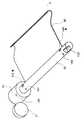
図8は、全て互いに固定して接続されている、バー32、作動レバー36、および第2のくわえづめアーム30についての考えられる構造を概略的に示している。作動レバー36に、矢印181、182によって表されるばね力に抗して動く作動レバー36を矢印180の方向に回転させるために、作動ピン37を作用させてもよい。バー32は、ばね力を生じるために、例えば板ばねを内部に嵌め込むことができる2つの溝183、184を有している。この板ばねの他端は、ハウジング3(図4を参照のこと)に取り付けることができる。バー32上の段部132も図示されている。
【0031】
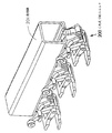
図9は、くわえづめユニット200を含む、本発明の第2の実施形態の側面図を示している。くわえづめユニット200は、突出部204、205(図11)が取り付けられたハウジング203を備えている。ハウジング203は、ローラ208(第2のローラ)およびローラ213(図12)がハウジング203上を動くことができるそれぞれ2つのローラ表面223、224を有している。
【0032】
図13、14で示すように、くわえづめユニット200は走行路201内を移動し、ハウジング203は例えば走行路201内を走行するチェーンにその上面が取り付けられている。図9、10、11、12に示すように、くわえづめユニット200は、印刷製品を把持する第1のくわえづめアーム220と第2のくわえづめアーム230とを備えている。第1のくわえづめアーム220は、突出部204、205に沿って転がることができるローラ206(第1のローラ)によって支持されており、この結果、くわえづめアーム220はハウジング203に対して摺動する。
【0033】
第2のくわえづめアーム230が、回転可能に揺動軸212(第1のピン)でアーム220に接続されている。概略的に図示したさらばねワッシャ部材210が、アーム220が後部位置(図9では左側)にあるとき、アーム230を開いた状態に保つ。このさらばね210の他端は、一端が、ローラ208に接続されたアーム209(支持アーム)に取り付けられ、他端がピン212に取り付けられている。ばね210は実際にはアーム230の内側に位置してもよいが、わかりやすくすために外側で図示している。
【0034】
アーム230は、ピン212のまわりをアーム220に対して回転可能に支持されており、このピン212もまたアーム214(他のアーム)の一端に接続されている。アーム214の他端は、揺動軸232(第2のピン)によって、ハウジング203内で回転可能に支持されたロッド245について回転可能なレバー242に接続されている。レバー242は、その一端に、カム250によって作動可能なカムフォロワ246を有している。
【0035】
第2の実施形態は、以下のように作動する。カム250がカムフォロワ246を下方に押すと、アーム214の一端で支持されたローラ213は、矢印215によって示される方向にローラ表面224に沿って上方に動かされる。同時にピン212は、概ね方向216の前方へアーム214によって引かれ、これによってくわえづめアーム220、230が前方へ摺動し、この結果、ローラ206は突出部204、205上を前方に転がる。アーム209もピン212によって前方に引かれ、この結果、ローラ208はローラ表面223に沿って転がり、図9に示すように下方に移動する。ばね210における張力はこのようにして減少し、そしてアーム230は印刷製品をアーム220、230の間で保持するように下方に移動する。ローラ213は、ローラ213が表面224における湾曲した位置の上方にとどまることができるので、この保持された位置でロックされ得る。この印刷製品を解放するために、カムフォロワ246を上方に、かつローラ213を下方に動かすカムを設けてもよい。
【0036】
第2の実施形態は、ラッチを必要としない点、また、ローラの転がりによって摩擦が減る点で、第1の実施形態よりも好適であると思われる。
【0037】
本明細書で用いられる「くわえづめアーム」という用語は、図に示すような折れ曲がったシートだけではなく、印刷製品を把持するために用いられるどのような構造をも含むことができ、本明細書で用いられる「ハウジング」という用語は、フレームまたはバーを含むどのような構造的なユニットを含むことができ、任意の部材を「収納する」必要はない。本明細書で用いられる「キャリッジ」は、移動可能な部材として広く定義されるものである。本明細書で用いられる「摺動」は、2つの部材間の滑らかな相対運動として定義されるものであり、転がり構造を含んでもよい。
本明細書には米国特許明細書第号の内容を引用している。
【図面の簡単な説明】
【図1】本発明の第1の実施形態における、走行路に沿って走行するくわえづめユニットの第1の側部を、開いた位置で示す図である。
【図2】ハウジングに対してくわえづめアームが前進した、図1のくわえづめユニットの第1の側を示す図である。
【図3】閉じた状態にロックされたくわえづめアームを有する、図1のくわえづめユニットの第1の側部を示す図である。
【図4】図2に示すくわえづめユニットの斜視図である。
【図5】図3のくわえづめユニットの第2の側部を示す図である。
【図6】くわえづめユニットのハウジングの後方に摺動されたくわえづめアームを有するくわえづめユニットの第2の側部を示す図である。
【図7】図6のくわえづめユニットについて、くわえづめアームがばねにより開いている状態を示す図である。
【図8】第1の実施形態のくわえづめユニットの第2のくわえづめアームとバーを示す概略図である。
【図9】本発明によるくわえづめユニットの第2の実施形態を示す側面図である。
【図10】第2の実施形態の後部および側部を示す斜視図である。
【図11】図9のくわえづめユニットを上方からみた斜視図である。
【図12】図9のくわえづめユニットを正面からみた斜視図である。
【図13】走行路内における第2の実施形態のくわえづめユニットを示す図である。
【図14】走行路内における第2の実施形態のくわえづめユニットを示す図である。
【符号の説明】
1 くわえづめユニット
2、201 走行路
3 ハウジング
5 印刷製品
10 第1の側部
110 第2の側部
11 上面部
12、112 溝
20 第1のくわえづめアーム
30 第2のくわえづめアーム
22、32 バー
14、114 キャリッジ
15 段部
36、42、44 アーム
37 作動ピン
40、140 ヒンジ
45、48、137、145、148、212 ピン
46、146、246 カムフォロワ
50、150、250 カム
60 中心線
142 第1のアーム
144 第2のアーム
150 第2のカムフォロワ
132 段部
133、216 方向
136 ラッチ
180、135、181、182 矢印
183、184 溝
200 くわえづめユニット
203 ハウジング
204、205 突出部
206、208、213 ローラ
209、214、220、230 アーム
210 さらばね
212、232 揺動軸
220 第1のくわえづめアーム
223、224 ローラ表面
230 第2のくわえづめアーム
242 レバー
245 ロッド
246 カムフォロワ
6、34、35、39、215 矢印[0001]
BACKGROUND OF THE INVENTION
The present invention generally relates to a printing press, and more particularly, to a transport device and a transport method for a printed product.
[0002]
[Prior art]
Web printing machines print a continuous web of material such as paper. This continuous web is then cut by a cutting unit to form a book block. These book blocks may be, for example, newspaper signatures. In order to transport or process these book blocks, i.e., to perform a finishing operation, for example, it is often less desirable to hold the book blocks firmly using a gripper that is movable along the travel path. Absent.
[0003]
U.S. Patent Application No. 5,727,783 discloses an apparatus for dispensing sheets of printed products. In this case, the plurality of grippers move along the traveling path at a predetermined pitch to grip the printed product.
[0004]
[Problems to be solved by the invention]
However, these printed products must be transferred to a speed reducer to be fixed and decelerated for their respective grippers. This transfer can cause damage to the printed product.
[0005]
It is an object of the present invention to provide an apparatus and method for holding and transporting a printed product so that the printed product moves relative to the gripper. An additional or other object of the present invention is to reduce the risk of damage to the printed product.
[0006]
[Means for Solving the Problems]
The present invention includes a housing and a first gripping arm and a second gripping arm for gripping a printed product, the first and second gripping arms sliding with respect to the housing. I will provide a. The housing is movable along the travel path.
[0007]
As the first and second gripper arms slide relative to the housing, the speed of the printed product held by the gripper arms varies with the speed of the travel path. This change in speed also occurs while the printed product is firmly held by the gripper arm.
[0008]
The first gripper arm is preferably attached to the first bar and the second gripper arm is preferably attached to the second bar. Each bar is attached to a carriage slidable at each end, i.e., in a groove formed in the side of the housing where an inverted U-shape is preferred. The first bar is preferably fixed at its end with respect to the carriage, and the second bar is fixed to prevent rotation of the second holding arm for gripping the printed product. Preferably it can be rotated to move towards the arm.
[0009]
The rotatable second bar is preferably spring-biased at its end against the carriage so that the second gripper arm is pushed to the open position.
[0010]
An actuating lever attached to the rotatable second bar and one of the carriages can move the second bar against the spring force so that the second gripper arm grips the printed product. . Furthermore, it can be locked in a state in which the cam follower is, beyond the center line to hold the closed position of the lever. The latch can then lock the lever in the closed position, so that the second bar cannot rotate back to the open position.
[0011]
Once the latch is unlocked, the printed product can be released because the spring biasing force of the second bar biases the second gripper arm to the open position.
[0012]
Also it includes a cam follower, the cam follower may be connected to the V-shaped hinge with two arms. One arm is connected to the housing side and the other arm is connected to a slidable carriage. It cams the cam follower to follow can flatten the V-shaped hinge such slidable carriage can be moved in the groove with respect to the housing. This hinge may be locked beyond the center line. Each side of the gripper unit preferably has a cam follower / hinge structures.
[0013]
The present invention includes a travel path and a plurality of gripper units that travel in the travel path. Each gripper unit includes a housing, a first gripper arm that grips a printed product, and a second gripper. And a first gripper arm and a second gripper arm that are slidably supported within the housing.
[0014]
The gripping device may further comprise a chain drive for driving the gripper unit, preferably at a constant speed. To vary the speed of the printed product while the printed product is held, it may comprise cams sliding the gripper arms of each gripper unit with respect to the housing. Cams may act on the cam follower mutually connected to a slidable carriage for supporting the arm grippers in the housing.
[0015]
The present invention further comprises a printed product comprising gripping the printed product with the gripper unit and moving the printed product relative to the gripper unit while the printed product remains held. A method of gripping is also provided. The printed product is preferably held by two gripping arms and then slides in a groove in the housing during this moving step. It is advantageous to use cam interaction to perform the sliding motion.
[0016]
The second gripper arm is preferably rotatable, and the method locks the second arm with a latch in a closed position and releases the latch to release the printed product. It is preferable that it contains.
[0017]
DETAILED DESCRIPTION OF THE INVENTION
Hereinafter, two preferred embodiments of the present invention will be described with reference to the drawings.
[0018]
FIG. 1 shows a gripping unit 1 that travels on a traveling path, that is, on a
[0019]
The second
[0020]
[0021]
Since the
[0022]
As shown in FIG. 3,
[0023]
The actuating
[0024]
FIG. 4 shows a perspective view of the gripping unit 1 shown in FIG. The
[0025]
FIG. 5 shows a side opposite to the side of the gripping unit 1 shown in FIG. Second
[0026]
A
[0027]
In this way, the gripping unit 1 can move along the traveling
[0028]
These cam followers are gripped printed product, i.e., to release the signature, depending on each of these cam follower cams pushed TOP position. Cams 1 50, as shown in FIG. 6, push up the
[0029]
Thus, the printed
[0030]
FIG. 8 schematically shows a possible structure for the
[0031]
FIG. 9 shows a side view of the second embodiment of the present invention including the gripper unit 200. The holding unit 200 includes a
[0032]
As shown in FIGS. 13 and 14, the gripper unit 200 moves in the travel path 201, and the
[0033]
The second
[0034]
The
[0035]
The second embodiment operates as follows. As the
[0036]
The second embodiment seems to be preferable to the first embodiment in that a latch is not required and the friction is reduced by the rolling of the roller.
[0037]
As used herein, the term “clamping arm” can include any structure used to grip a printed product, not just a folded sheet as shown in the figure. As used herein, the term “housing” can include any structural unit including a frame or bar, and does not need to “contain” any member. As used herein, “carriage” is broadly defined as a movable member. As used herein, “sliding” is defined as a smooth relative motion between two members and may include a rolling structure.
This specification refers to the contents of US Patent Specification.
[Brief description of the drawings]
FIG. 1 is a view showing a first side portion of a gripping unit that travels along a traveling path in an open position according to a first embodiment of the present invention.
FIG. 2 shows the first side of the gripper unit of FIG. 1 with the gripper arm advanced relative to the housing.
FIG. 3 shows the first side of the gripper unit of FIG. 1 with the gripper arm locked in the closed state.
4 is a perspective view of the gripper unit shown in FIG. 2. FIG.
FIG. 5 is a diagram showing a second side portion of the gripping unit of FIG. 3;
FIG. 6 is a view showing a second side portion of the gripping unit having a gripping arm slid to the rear of the housing of the gripping unit.
7 is a view showing a state in which the gripping arm is opened by a spring in the gripping unit of FIG. 6;
FIG. 8 is a schematic view showing a second gripping arm and a bar of the gripping unit of the first embodiment.
FIG. 9 is a side view showing a second embodiment of the gripping unit according to the present invention.
FIG. 10 is a perspective view showing a rear part and a side part of the second embodiment.
11 is a perspective view of the gripper unit of FIG. 9 as viewed from above.
12 is a perspective view of the gripper unit of FIG. 9 as seen from the front. FIG.
FIG. 13 is a diagram showing a gripping unit according to a second embodiment in a traveling path.
FIG. 14 is a diagram showing a gripping unit according to a second embodiment in a traveling path.
[Explanation of symbols]
DESCRIPTION OF SYMBOLS 1
Claims (11)
第1の溝および第2の溝を有するハウジングと、
印刷製品を把持する、第1のくわえづめアームおよび第2のくわえづめアームと、
前記第1の溝内で移動可能な第1のキャリッジと前記第2の溝内で移動可能な第2のキャリッジと、
前記第1のくわえづめアームが固定して接続されていると共に、前記第1および第2のキャリッジの間に回転不能に支持されている第1のバーと
前記第2のくわえづめアームが固定して接続されていると共に、前記第1および第2のキャリッジの間に回転可能に支持されている回転可能なバーと、
カムに追従して前記第1および第2のキャリッジを移動させるカムフォロアと、
前記回転可能なバーに固定して取り付けられた作動レバーと、
ピンを介して回転可能に取り付けられた第1および第2のアームを有する、前記第1および第2のキャリッジを移動させるヒンジと、
前記作動レバーと当接可能な作動ピンとを有し、
前記回転可能なバーは前記第2のくわえづめアームを開位置にするように前記第1および第2のキャリッジに対してばね付勢されており、前記ヒンジの前記第1のアームの一端は前記回転可能なバーに回転可能に取り付けられており、前記ヒンジの前記第1のアームの他端は前記カムフォロアが取り付けられており、前記ヒンジの前記第2のアームの一端は前記ハウジングに回転可能に取り付けられており、前記作動レバーは前記カムによる前記第1および第2のキャリッジの移動に伴って前記作動ピンと当接して該作動ピンにより押されることにより前記ばね付勢に抗して前記回転可能なバーを回転させる、移動可能なくわえづめユニット。It is a moveable unit that can move the transport device for printed products,
A housing having a first groove and a second groove;
A first gripper arm and a second gripper arm for gripping a printed product;
A first carriage movable in the first groove and a second carriage movable in the second groove;
The first holding arm is fixedly connected, and the first bar supported non-rotatably between the first and second carriages and the second holding arm is fixed. And a rotatable bar supported rotatably between the first and second carriages;
A cam follower for moving the first and second carriage to follow the cams,
An actuating lever fixedly attached to the rotatable bar ;
A hinge for moving the first and second carriages, having first and second arms rotatably mounted via pins;
An operating pin capable of contacting the operating lever ;
The rotatable bar is spring biased against the first and second carriages so that the second gripper arm is in an open position, and one end of the first arm of the hinge is The other end of the first arm of the hinge is attached to the rotatable bar, the cam follower is attached to the other end of the hinge, and the one end of the second arm of the hinge is rotatable to the housing. The actuating lever is attached to the actuating pin as the first and second carriages are moved by the cam and is pushed by the actuating pin so that the actuating lever can rotate against the spring bias. This is a movable, non-movable wobbling unit that rotates a simple bar.
該くわえづめユニットの走行路方向に延びる少なくとも1つの突出部と、ローラ表面とを有するハウジングと、
印刷製品を把持する、第1のくわえづめアームおよび第2のくわえづめアームと、
前記印刷製品を把持するために前記第2のくわえづめアームを移動させる支持アームと、
前記突出部および前記ローラ表面に対して前記第1および第2のくわえづめアームをそれぞれ摺動させる、前記第1および第2のくわえづめアームに接続された、カムと当接するカムフォロワと
一端に前記カムフォロワが設けられた前記ハウジングに回転可能に支持されたレバーとを有しており、
前記第1のくわえづめアームは少なくとも1つの第1のローラに接続され、前記少なくとも1つの第1のローラは前記少なくとも1つの突出部に沿って転がり、前記第2のくわえづめアームは第1のピンによって前記第1のくわえづめアームに接続され、かつ、開いた位置でばね付勢されており、前記第1のピンは前記支持アームに接続されており、前記支持アームはばねに接続されていると共に、前記ローラ表面に沿って転がる第2のローラに接続されており、前記ばねは前記第2のくわえづめアームに接続されており、前記レバーは他端において前記第1のピンに第2のピン及び他のアームを介して接続されており、前記少なくとも1つの突出部は前記カムにより前記カムフォロワが下方に押されると前記第1のローラを前記走行路方向において前方に転がし、前記突出部に沿う前記少なくとも1つの第1のローラの転がりに伴って前記ローラ表面は前記第2のローラを前記前方に下方に向かって転がし、前記支持アームは、前記第2のローラが前記ローラ表面を転がることにより、前記第2のくわえづめアームを前記印刷製品を把持するために移動させる、移動可能なくわえづめユニット。It is a moveable unit that can move the transport device for printed products,
A housing having at least one protrusion extending in the traveling path direction of the gripping unit and a roller surface;
A first gripper arm and a second gripper arm for gripping a printed product;
A support arm that moves the second gripping arm to grip the printed product;
Wherein each sliding said first and second gripper arm with respect to the projecting portion and the roller surface, which is connected to said first and second gripper arms, a cam follower in contact with the cam
A lever rotatably supported by the housing provided with the cam follower at one end ;
The first gripper arm is connected to at least one first roller, the at least one first roller rolls along the at least one protrusion, and the second gripper arm is a first The pin is connected to the first gripper arm and is spring-biased in an open position, the first pin is connected to the support arm, and the support arm is connected to the spring. And is connected to a second roller that rolls along the roller surface, the spring is connected to the second gripping arm, and the lever is secondly connected to the first pin at the other end. The at least one protrusion is connected to the first roller by the cam when the cam follower is pushed downward by the cam. Laying Oite forward, the roller surface along with the rolling of said at least one first roller along the protrusion roll downward the second roller to the front, the support arm, before Symbol A non-movable gripping unit that moves the second gripping arm to grip the printed product by a second roller rolling on the roller surface.
前記走行路と、
前記走行路内を走行する複数の請求項1乃至5のいずれか1項記載のくわえづめユニットとを有している搬送装置。A printed product conveying device,
The travel path;
A conveying device comprising a plurality of gripping units according to any one of claims 1 to 5 that travel in the traveling path.
前記くわえづめユニットで印刷製品を把持するステップと、
前記印刷製品が保持されている間に前記くわえづめユニットに対して前記印刷製品を移動させるステップとを含む、印刷製品の把持方法。A method for gripping a printed product in a printed product conveying apparatus having the gripping unit according to any one of claims 1 to 5 ,
Gripping the printed product with the gripper unit;
Moving the print product relative to the gripping unit while the print product is held.
Applications Claiming Priority (2)
| Application Number | Priority Date | Filing Date | Title |
|---|---|---|---|
| US09/488254 | 2000-01-20 | ||
| US09/488,254 US6357741B1 (en) | 2000-01-20 | 2000-01-20 | Velocity adjustable grippers on sliding carriage |
Publications (2)
| Publication Number | Publication Date |
|---|---|
| JP2001261208A JP2001261208A (en) | 2001-09-26 |
| JP4723099B2 true JP4723099B2 (en) | 2011-07-13 |
Family
ID=23938970
Family Applications (1)
| Application Number | Title | Priority Date | Filing Date |
|---|---|---|---|
| JP2001012994A Expired - Fee Related JP4723099B2 (en) | 2000-01-20 | 2001-01-22 | Movable gripper unit, gripping device, and printed product gripping method |
Country Status (5)
| Country | Link |
|---|---|
| US (1) | US6357741B1 (en) |
| EP (1) | EP1118563B1 (en) |
| JP (1) | JP4723099B2 (en) |
| AT (1) | ATE312040T1 (en) |
| DE (2) | DE10061703B4 (en) |
Families Citing this family (9)
| Publication number | Priority date | Publication date | Assignee | Title |
|---|---|---|---|---|
| DE10152843A1 (en) * | 2000-11-29 | 2002-06-13 | Heidelberger Druckmasch Ag | Sheet material position correction method for multi-color rotary printers, involves fixing sheet material to downline sheet guiding cylinder if actual position of sheet material deviates from nominal position |
| US6511065B1 (en) * | 2001-08-28 | 2003-01-28 | Heidelberger Druckmaschinen Ag | Method for transferring signatures and gripper assembly for a matched velocity transfer device |
| TWI261042B (en) * | 2003-10-08 | 2006-09-01 | Bobst Sa | Working station of a machine processing plate elements |
| US7530564B2 (en) * | 2006-07-10 | 2009-05-12 | Goss International Americas, Inc. | Opposing link gripper |
| US7694949B2 (en) * | 2006-09-18 | 2010-04-13 | Goss International Americas, Inc | Custodial lapped stream mechanism |
| DE102009001189A1 (en) * | 2009-02-26 | 2010-09-02 | Koenig & Bauer Aktiengesellschaft | Stacking device for sheet-fed offset rotary processing machine, has connection rod with ends, are guided with slide guide with respect to stacking frame such that finger and/or gripper unit are rotated with respect to connection points |
| DE202010002890U1 (en) * | 2010-02-26 | 2011-08-02 | Schunk Gmbh & Co. Kg Spann- Und Greiftechnik | gripping device |
| JP6263899B2 (en) * | 2013-08-15 | 2018-01-24 | グラドコジャパン株式会社 | Paper post-processing device |
| DE102016211172A1 (en) * | 2016-06-22 | 2017-12-28 | Krones Aktiengesellschaft | Device for handling articles and methods for their operation |
Citations (1)
| Publication number | Priority date | Publication date | Assignee | Title |
|---|---|---|---|---|
| JPH11501992A (en) * | 1995-10-26 | 1999-02-16 | レアー ロナル ゲーエムベーハー | Transfer device and transfer system for vertically guiding a plate-like object for chemical or electrolytic surface treatment |
Family Cites Families (16)
| Publication number | Priority date | Publication date | Assignee | Title |
|---|---|---|---|---|
| DE2136810B1 (en) * | 1971-07-23 | 1972-11-09 | Roland Offsetmaschinenfabrik Faber & Schleicher Ag, 6050 Offenbach | Control for the removal gripper of a sheet delivery on printing machines |
| US3948508A (en) * | 1973-12-24 | 1976-04-06 | Rank Xerox Ltd. | Sheet delivery apparatus |
| CH630583A5 (en) * | 1978-06-30 | 1982-06-30 | Ferag Ag | DEVICE FOR MOVING AWAY OF FLAT PRODUCTS INCLUDING IN A DOMESTIC FLOW, IN PARTICULAR PRINTED PRODUCTS. |
| AT384386B (en) * | 1983-06-28 | 1987-11-10 | Walter Sticht | EQUIPMENT FOR HANDLING OR POSITIONING OF COMPONENTS |
| DE3806646A1 (en) * | 1987-03-27 | 1989-01-26 | Schmale Carl Gmbh & Co Kg | Transport gripper for flat-shaped structures, in particular for textile webs |
| CH677652A5 (en) * | 1989-03-07 | 1991-06-14 | Grapha Holding Ag | |
| US5178262A (en) * | 1989-11-08 | 1993-01-12 | Grapha-Holding Ag | Sheet transporting tongs for use in chain conveyors and the like |
| JPH0597302A (en) * | 1991-10-09 | 1993-04-20 | Kaneda Kikai Seisakusho:Kk | Gripper for printed matter carrier |
| SE469890B (en) * | 1992-03-16 | 1993-10-04 | Wamag Idab Ab | Grab conveyor with permanently prestressed gripper |
| US5549442A (en) * | 1994-09-27 | 1996-08-27 | Leland D. Blatt | Article transfer apparatus |
| DE19523221C1 (en) * | 1995-06-27 | 1996-10-10 | Rudi Kirst | Parallel grips for robot arms or handling apparatus |
| ATE197033T1 (en) | 1995-07-20 | 2000-11-15 | Heidelberger Druckmasch Ag | METHOD AND DEVICE FOR DISPLAYING SHEET-SHAPED PRODUCTS |
| CH690301A5 (en) * | 1995-10-03 | 2000-07-14 | Ferag Ag | Clamp for holding flat objects has pliable support stirrup at both ends of which clamp jaws are pivotably located, with articulatedly interconnected lifting components on jaws |
| US5709120A (en) * | 1996-02-23 | 1998-01-20 | Shilling; Paul L. | Straight line drawing device |
| DE19712956A1 (en) * | 1997-03-27 | 1998-10-01 | Schunk Fritz Gmbh | Handling device |
| US6227588B1 (en) * | 1999-02-17 | 2001-05-08 | Heidelberger Druckmaschinen Aktiengesellschaft | Gripper assembly |
-
2000
- 2000-01-20 US US09/488,254 patent/US6357741B1/en not_active Expired - Lifetime
- 2000-12-12 DE DE10061703A patent/DE10061703B4/en not_active Expired - Fee Related
- 2000-12-14 EP EP00127209A patent/EP1118563B1/en not_active Expired - Lifetime
- 2000-12-14 DE DE50011814T patent/DE50011814D1/en not_active Expired - Lifetime
- 2000-12-14 AT AT00127209T patent/ATE312040T1/en not_active IP Right Cessation
-
2001
- 2001-01-22 JP JP2001012994A patent/JP4723099B2/en not_active Expired - Fee Related
Patent Citations (1)
| Publication number | Priority date | Publication date | Assignee | Title |
|---|---|---|---|---|
| JPH11501992A (en) * | 1995-10-26 | 1999-02-16 | レアー ロナル ゲーエムベーハー | Transfer device and transfer system for vertically guiding a plate-like object for chemical or electrolytic surface treatment |
Also Published As
| Publication number | Publication date |
|---|---|
| JP2001261208A (en) | 2001-09-26 |
| ATE312040T1 (en) | 2005-12-15 |
| EP1118563B1 (en) | 2005-12-07 |
| DE10061703B4 (en) | 2012-10-31 |
| DE50011814D1 (en) | 2006-01-12 |
| US6357741B1 (en) | 2002-03-19 |
| DE10061703A1 (en) | 2001-07-26 |
| EP1118563A3 (en) | 2003-06-18 |
| EP1118563A2 (en) | 2001-07-25 |
Similar Documents
| Publication | Publication Date | Title |
|---|---|---|
| JP4723099B2 (en) | Movable gripper unit, gripping device, and printed product gripping method | |
| CN1033442C (en) | Folding machine for producing folded copies from a web of printed paper | |
| JP3385051B2 (en) | Method and apparatus for opening a self-closing gripper on a gripper conveyor | |
| JP6611941B2 (en) | Media alignment using puller clamps | |
| JP2700287B2 (en) | Method and apparatus for opening folded prints | |
| US5992610A (en) | Method and device for producing a rotated stream with a corner gripper | |
| JPH0240572B2 (en) | ||
| AU711463B2 (en) | Arrangement for transporting metallised belts in a machine for transferring metallised images onto sheet elements | |
| US5740900A (en) | Apparatus for splitting a product stream | |
| US5876320A (en) | Universal half folder apparatus | |
| JP2002003040A (en) | Device of taking out printed product conveyed on conveying device at regular interval | |
| JP3793948B2 (en) | Printed product conveying device with gripping mechanism | |
| JP2001213572A (en) | Paper guide barrel, folder, and method of operating product gripping member | |
| US6067883A (en) | Method and apparatus for providing positive control of a printable medium in a printing system | |
| US6736061B2 (en) | Rotary signature transfer device | |
| JPH04226333A (en) | Feed table for feed station of machine to cut and print sheet-like processed product for manufacture into package | |
| JP2007216682A (en) | Book block carrier system | |
| JPH05201169A (en) | Method and apparatus for processing printed matter | |
| JP4074649B2 (en) | The body of the folding device having a body and at least one gripper | |
| JP4805449B2 (en) | Linear folding apparatus and method | |
| US2855996A (en) | Conveyor for flexible sheets | |
| JP3129447B2 (en) | Equipment for delivery of printed products | |
| JP2006248785A (en) | Device for opening and placing folded-up paper sheet | |
| JP3718536B2 (en) | Paper discharge device for sheet-fed printing press | |
| JP2004035266A (en) | Sheet material carrying device equipped with adjustable top gripper for pocket |
Legal Events
| Date | Code | Title | Description |
|---|---|---|---|
| A711 | Notification of change in applicant |
Free format text: JAPANESE INTERMEDIATE CODE: A711 Effective date: 20050909 |
|
| A521 | Request for written amendment filed |
Free format text: JAPANESE INTERMEDIATE CODE: A523 Effective date: 20051116 |
|
| A711 | Notification of change in applicant |
Free format text: JAPANESE INTERMEDIATE CODE: A711 Effective date: 20060224 |
|
| A621 | Written request for application examination |
Free format text: JAPANESE INTERMEDIATE CODE: A621 Effective date: 20070206 |
|
| A977 | Report on retrieval |
Free format text: JAPANESE INTERMEDIATE CODE: A971007 Effective date: 20090305 |
|
| A131 | Notification of reasons for refusal |
Free format text: JAPANESE INTERMEDIATE CODE: A131 Effective date: 20090311 |
|
| A521 | Request for written amendment filed |
Free format text: JAPANESE INTERMEDIATE CODE: A523 Effective date: 20090610 |
|
| RD13 | Notification of appointment of power of sub attorney |
Free format text: JAPANESE INTERMEDIATE CODE: A7433 Effective date: 20100326 |
|
| A131 | Notification of reasons for refusal |
Free format text: JAPANESE INTERMEDIATE CODE: A131 Effective date: 20100401 |
|
| A521 | Request for written amendment filed |
Free format text: JAPANESE INTERMEDIATE CODE: A821 Effective date: 20100329 |
|
| A521 | Request for written amendment filed |
Free format text: JAPANESE INTERMEDIATE CODE: A523 Effective date: 20100630 |
|
| A131 | Notification of reasons for refusal |
Free format text: JAPANESE INTERMEDIATE CODE: A131 Effective date: 20101105 |
|
| RD04 | Notification of resignation of power of attorney |
Free format text: JAPANESE INTERMEDIATE CODE: A7424 Effective date: 20101228 |
|
| A521 | Request for written amendment filed |
Free format text: JAPANESE INTERMEDIATE CODE: A523 Effective date: 20110207 |
|
| A01 | Written decision to grant a patent or to grant a registration (utility model) |
Free format text: JAPANESE INTERMEDIATE CODE: A01 Effective date: 20110309 |
|
| A01 | Written decision to grant a patent or to grant a registration (utility model) |
Free format text: JAPANESE INTERMEDIATE CODE: A01 |
|
| A61 | First payment of annual fees (during grant procedure) |
Free format text: JAPANESE INTERMEDIATE CODE: A61 Effective date: 20110407 |
|
| FPAY | Renewal fee payment (event date is renewal date of database) |
Free format text: PAYMENT UNTIL: 20140415 Year of fee payment: 3 |
|
| R150 | Certificate of patent or registration of utility model |
Free format text: JAPANESE INTERMEDIATE CODE: R150 |
|
| LAPS | Cancellation because of no payment of annual fees |