JP4722366B2 - Extrusion die - Google Patents
Extrusion die Download PDFInfo
- Publication number
- JP4722366B2 JP4722366B2 JP2001572233A JP2001572233A JP4722366B2 JP 4722366 B2 JP4722366 B2 JP 4722366B2 JP 2001572233 A JP2001572233 A JP 2001572233A JP 2001572233 A JP2001572233 A JP 2001572233A JP 4722366 B2 JP4722366 B2 JP 4722366B2
- Authority
- JP
- Japan
- Prior art keywords
- die
- die cavity
- leading edge
- cavity
- male
- Prior art date
- Legal status (The legal status is an assumption and is not a legal conclusion. Google has not performed a legal analysis and makes no representation as to the accuracy of the status listed.)
- Expired - Fee Related
Links
Images


Classifications
-
- B—PERFORMING OPERATIONS; TRANSPORTING
- B21—MECHANICAL METAL-WORKING WITHOUT ESSENTIALLY REMOVING MATERIAL; PUNCHING METAL
- B21C—MANUFACTURE OF METAL SHEETS, WIRE, RODS, TUBES OR PROFILES, OTHERWISE THAN BY ROLLING; AUXILIARY OPERATIONS USED IN CONNECTION WITH METAL-WORKING WITHOUT ESSENTIALLY REMOVING MATERIAL
- B21C25/00—Profiling tools for metal extruding
- B21C25/10—Making tools by operations not covered by a single other subclass
-
- A—HUMAN NECESSITIES
- A61—MEDICAL OR VETERINARY SCIENCE; HYGIENE
- A61P—SPECIFIC THERAPEUTIC ACTIVITY OF CHEMICAL COMPOUNDS OR MEDICINAL PREPARATIONS
- A61P11/00—Drugs for disorders of the respiratory system
-
- A—HUMAN NECESSITIES
- A61—MEDICAL OR VETERINARY SCIENCE; HYGIENE
- A61P—SPECIFIC THERAPEUTIC ACTIVITY OF CHEMICAL COMPOUNDS OR MEDICINAL PREPARATIONS
- A61P11/00—Drugs for disorders of the respiratory system
- A61P11/06—Antiasthmatics
-
- A—HUMAN NECESSITIES
- A61—MEDICAL OR VETERINARY SCIENCE; HYGIENE
- A61P—SPECIFIC THERAPEUTIC ACTIVITY OF CHEMICAL COMPOUNDS OR MEDICINAL PREPARATIONS
- A61P17/00—Drugs for dermatological disorders
-
- A—HUMAN NECESSITIES
- A61—MEDICAL OR VETERINARY SCIENCE; HYGIENE
- A61P—SPECIFIC THERAPEUTIC ACTIVITY OF CHEMICAL COMPOUNDS OR MEDICINAL PREPARATIONS
- A61P17/00—Drugs for dermatological disorders
- A61P17/02—Drugs for dermatological disorders for treating wounds, ulcers, burns, scars, keloids, or the like
-
- A—HUMAN NECESSITIES
- A61—MEDICAL OR VETERINARY SCIENCE; HYGIENE
- A61P—SPECIFIC THERAPEUTIC ACTIVITY OF CHEMICAL COMPOUNDS OR MEDICINAL PREPARATIONS
- A61P17/00—Drugs for dermatological disorders
- A61P17/04—Antipruritics
-
- A—HUMAN NECESSITIES
- A61—MEDICAL OR VETERINARY SCIENCE; HYGIENE
- A61P—SPECIFIC THERAPEUTIC ACTIVITY OF CHEMICAL COMPOUNDS OR MEDICINAL PREPARATIONS
- A61P17/00—Drugs for dermatological disorders
- A61P17/06—Antipsoriatics
-
- A—HUMAN NECESSITIES
- A61—MEDICAL OR VETERINARY SCIENCE; HYGIENE
- A61P—SPECIFIC THERAPEUTIC ACTIVITY OF CHEMICAL COMPOUNDS OR MEDICINAL PREPARATIONS
- A61P17/00—Drugs for dermatological disorders
- A61P17/14—Drugs for dermatological disorders for baldness or alopecia
-
- A—HUMAN NECESSITIES
- A61—MEDICAL OR VETERINARY SCIENCE; HYGIENE
- A61P—SPECIFIC THERAPEUTIC ACTIVITY OF CHEMICAL COMPOUNDS OR MEDICINAL PREPARATIONS
- A61P19/00—Drugs for skeletal disorders
- A61P19/02—Drugs for skeletal disorders for joint disorders, e.g. arthritis, arthrosis
-
- A—HUMAN NECESSITIES
- A61—MEDICAL OR VETERINARY SCIENCE; HYGIENE
- A61P—SPECIFIC THERAPEUTIC ACTIVITY OF CHEMICAL COMPOUNDS OR MEDICINAL PREPARATIONS
- A61P19/00—Drugs for skeletal disorders
- A61P19/08—Drugs for skeletal disorders for bone diseases, e.g. rachitism, Paget's disease
-
- A—HUMAN NECESSITIES
- A61—MEDICAL OR VETERINARY SCIENCE; HYGIENE
- A61P—SPECIFIC THERAPEUTIC ACTIVITY OF CHEMICAL COMPOUNDS OR MEDICINAL PREPARATIONS
- A61P19/00—Drugs for skeletal disorders
- A61P19/08—Drugs for skeletal disorders for bone diseases, e.g. rachitism, Paget's disease
- A61P19/10—Drugs for skeletal disorders for bone diseases, e.g. rachitism, Paget's disease for osteoporosis
-
- A—HUMAN NECESSITIES
- A61—MEDICAL OR VETERINARY SCIENCE; HYGIENE
- A61P—SPECIFIC THERAPEUTIC ACTIVITY OF CHEMICAL COMPOUNDS OR MEDICINAL PREPARATIONS
- A61P25/00—Drugs for disorders of the nervous system
-
- A—HUMAN NECESSITIES
- A61—MEDICAL OR VETERINARY SCIENCE; HYGIENE
- A61P—SPECIFIC THERAPEUTIC ACTIVITY OF CHEMICAL COMPOUNDS OR MEDICINAL PREPARATIONS
- A61P25/00—Drugs for disorders of the nervous system
- A61P25/02—Drugs for disorders of the nervous system for peripheral neuropathies
-
- A—HUMAN NECESSITIES
- A61—MEDICAL OR VETERINARY SCIENCE; HYGIENE
- A61P—SPECIFIC THERAPEUTIC ACTIVITY OF CHEMICAL COMPOUNDS OR MEDICINAL PREPARATIONS
- A61P29/00—Non-central analgesic, antipyretic or antiinflammatory agents, e.g. antirheumatic agents; Non-steroidal antiinflammatory drugs [NSAID]
-
- A—HUMAN NECESSITIES
- A61—MEDICAL OR VETERINARY SCIENCE; HYGIENE
- A61P—SPECIFIC THERAPEUTIC ACTIVITY OF CHEMICAL COMPOUNDS OR MEDICINAL PREPARATIONS
- A61P3/00—Drugs for disorders of the metabolism
- A61P3/08—Drugs for disorders of the metabolism for glucose homeostasis
- A61P3/10—Drugs for disorders of the metabolism for glucose homeostasis for hyperglycaemia, e.g. antidiabetics
-
- A—HUMAN NECESSITIES
- A61—MEDICAL OR VETERINARY SCIENCE; HYGIENE
- A61P—SPECIFIC THERAPEUTIC ACTIVITY OF CHEMICAL COMPOUNDS OR MEDICINAL PREPARATIONS
- A61P3/00—Drugs for disorders of the metabolism
- A61P3/12—Drugs for disorders of the metabolism for electrolyte homeostasis
- A61P3/14—Drugs for disorders of the metabolism for electrolyte homeostasis for calcium homeostasis
-
- A—HUMAN NECESSITIES
- A61—MEDICAL OR VETERINARY SCIENCE; HYGIENE
- A61P—SPECIFIC THERAPEUTIC ACTIVITY OF CHEMICAL COMPOUNDS OR MEDICINAL PREPARATIONS
- A61P35/00—Antineoplastic agents
-
- A—HUMAN NECESSITIES
- A61—MEDICAL OR VETERINARY SCIENCE; HYGIENE
- A61P—SPECIFIC THERAPEUTIC ACTIVITY OF CHEMICAL COMPOUNDS OR MEDICINAL PREPARATIONS
- A61P35/00—Antineoplastic agents
- A61P35/02—Antineoplastic agents specific for leukemia
-
- A—HUMAN NECESSITIES
- A61—MEDICAL OR VETERINARY SCIENCE; HYGIENE
- A61P—SPECIFIC THERAPEUTIC ACTIVITY OF CHEMICAL COMPOUNDS OR MEDICINAL PREPARATIONS
- A61P37/00—Drugs for immunological or allergic disorders
-
- A—HUMAN NECESSITIES
- A61—MEDICAL OR VETERINARY SCIENCE; HYGIENE
- A61P—SPECIFIC THERAPEUTIC ACTIVITY OF CHEMICAL COMPOUNDS OR MEDICINAL PREPARATIONS
- A61P9/00—Drugs for disorders of the cardiovascular system
- A61P9/10—Drugs for disorders of the cardiovascular system for treating ischaemic or atherosclerotic diseases, e.g. antianginal drugs, coronary vasodilators, drugs for myocardial infarction, retinopathy, cerebrovascula insufficiency, renal arteriosclerosis
-
- B—PERFORMING OPERATIONS; TRANSPORTING
- B21—MECHANICAL METAL-WORKING WITHOUT ESSENTIALLY REMOVING MATERIAL; PUNCHING METAL
- B21C—MANUFACTURE OF METAL SHEETS, WIRE, RODS, TUBES OR PROFILES, OTHERWISE THAN BY ROLLING; AUXILIARY OPERATIONS USED IN CONNECTION WITH METAL-WORKING WITHOUT ESSENTIALLY REMOVING MATERIAL
- B21C25/00—Profiling tools for metal extruding
- B21C25/02—Dies
Abstract
Description
【0001】
本発明は、金属材料の押出しで使用するための押出しダイに関し、詳細には、アルミニウムの押出しで使用するのに適したダイに関する。本発明は、更に、この種のダイの製造方法に関する。
【0002】
アルミニウムの押出しを行うとき、押出ダイを通るアルミニウムの移動速度がダイに亘って均一であることが重要である。これは、従来、有限の支持長のダイキャビティを持つダイを使用して、ダイに亘る支持長を変化させることによって行われてきた。しかしながら、押出製品は、支持面と押出されるアルミニウムとの間の係合により生じる表面欠陥を含む場合がある。支持面をダイキャビティへの入口の下流に設けるのではなく、いわゆるゼロ支持を持つダイを使用し、支持長が変化するダイキャビティの上流にチャンバを形成し、ダイに亘る押出し速度を制御することが既知である。ゼロ支持という用語は、支持長がゼロのダイキャビティを意味するけれども、実際には、ダイキャビティは、有限であるが非常に小さい支持長を持つことが多い。
【0003】
アルミニウムを押出す場合に直面する別の問題点は、押出体が例えばチャンネル形材である場合、チャンネルの側部が撓み易く、かくしてチャンネルの側部を形成するダイの部分が互いに平行なダイキャビティを含むようにダイが形成されている場合には、このダイを使用して押出された部材の側部が互いに平行でなくスプレー(splay)するということである。このようなスプレーを補正するため、ダイキャビティの上流に配置された予備チャンバを設けることが既知である。この予備チャンバの幅は、直ぐ隣にあるダイキャビティの部分よりも大きく、予備チャンバは、ダイキャビティに対して横方向にオフセットされている。このような技術により、押出される金属に側方荷重が加わる。予備チャンバをダイキャビティから横方向にオフセットすることにより、場合によってはスプレーを補正できるがこれは限られた用途であり、例えば壁厚が比較的薄い押出体におけるスプレーを補正するのに十分な力を加えることはできない。雄部分及び雌部分を含むダイを使用して中空部材を押出す場合にも同様の問題が生じる。
【0004】
本発明によれば、ダイキャビティが内部に形成されたダイ本体を含み、このダイ本体は、雌部分内に突出した雄部分を画成し、雄部分によって画成されたダイキャビティの部分の前縁及び雌部分によって画成されたダイキャビティの部分の前縁は、ダイが使用されていない場合、同一平面内にない、押出ダイが提供される。
【0005】
従来の構成では、押出し中の金属に加わる荷重、及び従ってダイに加わる荷重は、雄部分を雌部分に対して撓ませるのに十分である。ダイがゼロ支持ダイである場合、このような撓みによりダイキャビティの前縁は押出し方向で間隔が隔てられる。このような間隔により、押出し中の金属に側方荷重が加わり、その結果、上文中に説明したようにスプレーが生じる。休止時に前縁が同一平面内にないようにダイを設計することによって、使用時に撓みが生じた場合に前縁が同一平面内にあるか或いは実質的に同一平面内にあるようにダイを構成できるため、この効果を小さくできる。前縁が同一平面内にくるのが便利であるけれども、本発明の利点は、ダイに亘って、キャビティの一方の側部の部分の前縁がキャビティの他方の側部の部分と整合する場合にも得られる。
【0006】
一般的には、雄部分及び雌部分の両方が撓み、本発明が較正しようとするのはこれらの部分間の相対的な撓みであるということに着目されたい。
【0007】
本明細書中の説明は撓みに関するが、使用時に荷重が加わることにより、ダイの材料の、ある程度の圧縮が生じるということは明らかであり、本発明は、使用時のこのような圧縮により生じる支持部の不整合と関連した欠点を解決するのにも使用できる。
【0008】
ダイキャビティは、好ましくは、その幅が、その前縁と隣接した最小値から増大するように形成されている。このような構成を、下文において、ゼロ支持ダイと呼ぶ。
【0009】
本発明は、比較的小さい撓み量によりこのようなダイの支持部の全体としての不整合が生じるため、ゼロ支持ダイで特に有利である。非ゼロ型のダイでは、撓みが生じた場合でも、各支持面の部分が向き合った支持面の部分と整合したままである。
【0010】
ダイキャビティは、雄部分及び雌部分を画成するように形成されていてもよく、雄部分はタング部分の形態をとる。このような構成では、ダイは、任意の断面形状の少なくとも一つの細長いチャンネルを持つ押出部材を形成するのに使用される。
【0011】
ダイキャビティは、少なくとも一つの別のタング部分を画成するように形成されていてもよい。ダイ本体は、少なくとも一つの別のダイキャビティを画成してもよい。
【0012】
ダイ本体は、実質的に平らな前面、この前面に設けられた溝、及びダイキャビティと溝との間の交差部に画成されたダイキャビティの前縁を備えていてもよく、溝の深さは不均一である。
【0013】
別の態様では、ダイ本体は、ダイキャビティの前縁を画成するように機械加工された平らでない前面を備えていてもよい。
【0014】
ダイに亘って均一な押出し速度が得られるように形成された予備形成チャンバがダイキャビティの上流に配置されているのがよい。予備形成チャンバは、深さが不均一であってもよく、及び従って、支持長が不均一であってもよく、及び/又は幅が不均一であってもよい。
【0015】
変形例の構成では、ダイは、中空形態の細長い部材を製造するように設計されていてもよく、雄部分が雌部分によって形成された開口部内に突出している。
【0016】
本発明の別の特徴によれば、使用時にダイの雄部分の起こるであろう撓みを計算する工程、及びダイのダイキャビティの少なくとも部分の周囲に凹所を形成する工程を含み、凹所の深さが不均一であり、使用時に、キャビティの一方の側部のダイキャビティの部分の前縁がキャビティの向き合った側部の前縁と整合するように形成される、押出しダイの製造方法が提供される。
【0017】
凹所は、便利には、研削作業を使用して形成されるが、他の技術を使用することができるということは理解されよう。
【0018】
起こるであろう撓みを計算する工程は、便利には、有限要素分析技術を使用して行われる。
【0019】
本発明を添付図面を参照して以下に詳細に説明する。
【0020】
【発明の実施の形態】
図1乃至図4を参照する。図1には、比較的複雑な形状の押出アルミニウム部材10が示してある。この部材10は、リム(limb)14を含むチャンネル状領域12と考えられる幾つかの領域を含む。これらのリムは、互いに対して全体に平行である。図1に示すチャンネル状領域12の幾つかを形成する対をなしたリム14には、図において、参照番号14a、14b、及び14cが付してある。
【0021】
図2は、部材10の製造で使用するための押出ダイのダイ本体16の部分を示す。ダイ本体16には、一対のダイキャビティ18を画成する開口部が設けられている。各ダイキャビティ18は、部材10の製造で使用するように設計されている。図3は、一方のダイキャビティ18を詳細に示す。
【0022】
図3に示すように、各ダイキャビティ18は、押出されるべき部材10の断面形状と形態がほぼ一致する形状の開口部を含む。キャビティ18の幅は、キャビティ18の前縁18a、18bと隣接した最小幅(図4参照)から増大し、かくして、このダイはゼロ支持型である。
【0023】
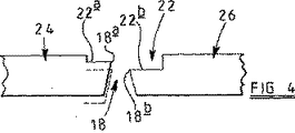
ダイ本体16の前縁面は全体に平らな形態であり、凹所20が設けられている。この凹所は全体形状がキャビティ18と同じであるが、幅が大きい。追加の凹所22(図4参照)が凹所20のベースに形成されている。この凹所22もまた、全体形状がダイキャビティ18と同じであるが、幅が大きい。図4に示すように、ダイキャビティ18の前縁18a、18bはダイキャビティ18と凹所22との交差部に画成される。
【0024】
図3に最もよく示すように、使用時にリム14の各対を形成する、ダイキャビティ18の部分間に配置されたダイ本体16の部分は、タング部分24の形態をとり、これはダイ本体16の対応する形状の雌部分26内に受入れられる。使用時に、押出されるべき材料に荷重を加えることによってタング部分24を雌部分26に対して撓ませる傾向がある。このような撓みにより部材10のリム14がスプレーされる危険を小さくするため、又はこれらのリムがスプレーされる程度を小さくするため、ダイは、ダイが使用されていない場合に、タング部分24の部分が画成するダイキャビティ18の前縁18aが、雌部分26の部分によって画成された前縁と同一平面内になく、タング部分24の撓み(図4に破線で示す位置への撓み)により、関連した前縁18aを雌部分26と関連した前縁18bを含む平面に近づけ、好ましくは同じ平面内に置くように位置決めされる方法で製造される。使用時に前縁18a、18平面が実質的に同一平面内にあるようにすることによって、押し出される材料に側方荷重を加え、及び従って、リム14のスプレーを少なくできる。
【0025】
図1乃至図4の実施形態では、凹所22の深さは均一でなく、むしろ、図4に示すように、ダイキャビティ18の一方の側部に深さが比較的小さい領域22aを含み、ダイキャビティ18の他方の側部に深さが比較的大きい領域22bを含む。領域22aはタング部分24に設けられており、領域22a及び領域22bの深さは、使用時にタング部分24がそれらの撓み位置をとったとき、前縁18a、18bが実質的に同一平面内にあるように選択される。
【0026】
所望であれば、凹所22は、ダイの幾つかの部分においてダイキャビティ18の開口部から横方向にオフセットでき、このような横方向オフセットによっても、押出される金属に側方荷重が加わり、従来の方法におけるリム14のスプレーを補正する。この技術は、例えば、リム14のスプレーの量が比較的小さい場合に使用でき、この技術を使用して比較的容易に補正でき、又は深さが異なる凹所22の提供部分の使用が実際的でない場合、又はこの技術を使用してスプレーを完全に補正することは実際的でない場合に使用できる。
【0027】
上文中に説明したように、使用にあたっては、ダイキャビティの前縁は、同一平面内にくるか或いは実質的に同一平面内にあるが、必ずしもそうでなくてもよい。本発明の利点を得るために必要とされることは、使用にあたり、ダイキャビティの両側部の前縁を互いに整合させるか或いは実質的に整合させることだけである。ダイの一方の部分の前縁が整合した平面は、必ずしもダイキャビティの他方の部分の前縁が整合した平面と同じでなくてもよい。
【0028】
図5は、図1乃至図4の構成に対する変形例を示す。図5の構成では、前縁18a、18bが同一平面内にないようにするために凹所22を使用する代わりに、ダイ本体16の前縁面が平らな形態でなく、例えばタング部分24を画成するダイ本体16の部分の前縁面が雌部分26を画成する部分に対して持ち上がっているように形成されている。
【0029】
本明細書中上文中に説明した構成の両方において、押出し方向での前縁18a、18bの間隔は、ダイの面に亘って滑らかに且つ連続的に、例えばタング部分24のチップでの最大値からそこから遠方の端部での最小値まで変化するということは理解されよう。
【0030】
上文中に説明した構成において、凹所22は底が平らな形態を備えているが、所望であれば、角度をなした形態であってもよい。所望であれば、様々な支持長又は形状の流れ制御予備チャンバをダイキャビティの上流に設け、ダイを横切る押出し速度を実質的に均一にしてもよい。別の態様では、様々な支持長の支持面をダイキャビティの前縁18a、18bの下流に設けることにより、この効果を得ることができる。更に、以上の説明において、タング部分24は側部が平行な形態であるが、必ずしもそうでなくてもよく、本発明は、例えば湾曲形態やV形状断面等の任意の形状のタング部分を持つダイに適用できるということは理解されよう。幾つかのV形状タング部分を図3に示し、これに参照番号28が付してある。
【0031】
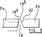
タング部分の撓み距離、及び従って、休止時にダイキャビティの前縁が離間されなければならない距離は、非常に小さい。図6は、幾つかのタング部分24及び対応する雌部分26を各々含む四つのダイキャビティが形成されたダイを示す。図7は、図6に示すキャビティ18のうちの一つの拡大図である。図7では、影を付けた部分がダイキャビティ18である。凹所22がダイキャビティ18の部分の周囲に形成されており、その結果、タング部分24によって画成されたキャビティの部分の前縁18aは一つの平面内にあり、雌部分26によって画成された前縁18bはその平面の外にある。凹所22は、雌部分26にだけ形成されており、深さは均一でない。様々な場所での凹所22の深さが図面に書き込んである。更に、凹所22は底が平らな形態でなく、図8に示すように角度をなした形態である。
【0032】
図9は、断面が異なる部材を製造するためのダイを示す。このダイは二つのダイキャビティを含む。ダイ本体に加わる荷重は均一でなく、ダイ本体の縁部からの距離に応じて変化する。その結果、ダイの中心近くに配置されたタング部分の撓みの量は、ダイ本体の縁部近くに位置決めされた同様のタング部分とは異なる。ダイキャビティの前縁の休止時の間隔をこれに従って変更しなければならず、図9は、休止時の二つのダイキャビティ18の周囲の様々な点での前縁18a、18bの間隔を示す。
【0033】
図9を図2と比較すると、図9では二つのキャビティが互いに同じであるが、図2のキャビティでは互いに鏡像をなしている。同じ押出体を製造するのが有利である。これは、押出し直後に実施される任意の処理プロセスを簡単にできるためである。本発明の技術により、同じ押出体を製造するように構成された幾つかのキャビティを含むダイで製造を比較的容易に行うことができる。図9では、チャンバ22は、押出されるべき金属が二つのダイキャビティ18に正しい割合で供給されるように寸法が定められている。
【0034】
図10及び図11に示す構成は、中空部材の押出しで使用するようになっているという点で上文中に説明し且つ例示した構成と異なる。ダイは、複数の開口部を画成する雌部分30を含む。各開口部は雄部分32の部分を受入れる。雄部分32及び雌部分30は、その間にダイキャビティ18を画成する。各ダイキャビティ18はゼロ支持形態であり、雄部分32及び雌部分30によって画成された前縁18aを含む。雄部分32は、使用時に、雌部分30に対して上文中に説明したように撓む。このような撓みは、代表的な構成では、前縁18a及び18bを不整合にする。本発明によれば、ダイは、雄部分32が画成する前縁18aが、休止時に、雌部分30が画成する前縁から押出し方向に離間されるように設計されており、そのため、使用時に雄部分32が撓むことにより、前縁18a、18bの間隔が減少し、かくして、例えば、円形断面の押出体が楕円形になる傾向を小さくする。好ましくは、前縁18a、18bの間隔は、使用時に、押出し方向でゼロにまで減少するが、場合によっては、間隔を非常に小さな量にまで減少させてもよい。
【0035】
本発明による押出ダイを製造するため、使用時にダイの各部分がどれ程撓むのかを決定することが重要である。撓みが決定された後、撓んだ使用時の状態において、ダイの全ての部分について、ダイキャビティの一方の側部の前縁がキャビティの反対側の前縁と整合し又は実質的に整合するようにダイを設計できる。
【0036】
どれ程の撓みが生じるのかを様々な技術を使用して決定できる。例えば、当業者は、どれほどの撓みが生じる可能性があるのかを、彼自身の知識からかなりの精度で決定できる。変形例の技術では、ダイの部分が被る可能性のある力を決定するため、及び従って、これらの部分がどれ程撓むのかを決定するためにコンピュータによるモデル化を使用できる。モデル化は、便利には有限要素分析法を使用する。別の技術では、キャビティを持ち且つ製造されるべきダイと同様の他の特徴を持つダイに荷重を加え、その部分の撓みを計測する。
【0037】
生じる可能性がある撓みを決定した後、撓み状態にある場合に前縁が適正に整合するように、ダイキャビティの周囲に凹所を形成し、これらの凹所を付形し、詳細にはこれらの凹所の深さを制御する。凹所は、便利には、研削プロセスを使用して形成される。図12は、截頭円錐形形状の研削面42を持つ研削ホイール40を示す。研削ホイール40は、所期の押出方向に対して角度をなした軸線を中心として回転し、ベースがダイの前面に対して10°の角度をなす凹所を形成するように取り付けられている。ホイール40の直径は、便利には、約15mmである。
【0038】
ダイの耐磨耗性を改善するため、好ましくは、窒化プロセスもまた施される。
【0039】
上文中に説明したように研削技術を使用して凹所を形成できるけれども、所望であれば、他の技術を使用することができる。
【図面の簡単な説明】
【図1】 押出アルミニウム部材の断面図である。
【図2】 図1の部材の押出しで使用されるダイの部分図である。
【図3】 図2の部分の拡大図である。
【図4】 図3の4−4線に沿った概略断面図である。
【図5】 変形例を示す図4と同様の図である。
【図6】 変形例のダイを示す図2と同様の図である。
【図7】 図6のダイの1つのダイキャビティを示す概略図である。
【図8】 図7の8−8線に沿った概略断面図である。
【図9】 別の変形例のダイを示す図6と同様の図である。
【図10】 変形例のダイを示す概略断面図である。
【図11】 図10のダイを示す平面図である。
【図12】 図1乃至図11のダイの製造に使用される方法の部分を示す概略図である。[0001]
The present invention relates to an extrusion die for use in the extrusion of metallic materials, and in particular to a die suitable for use in the extrusion of aluminum. The invention further relates to a method for manufacturing such a die.
[0002]
When extruding aluminum, it is important that the speed of movement of the aluminum through the extrusion die is uniform across the die. This has traditionally been done by using a die having a finite support length die cavity and varying the support length across the die. However, the extruded product may contain surface defects caused by the engagement between the support surface and the extruded aluminum. Rather than providing a support surface downstream of the entrance to the die cavity, use a die with a so-called zero support and form a chamber upstream of the die cavity where the support length varies to control the extrusion rate across the die Is known. Although the term zero support means a die cavity with zero support length, in practice, die cavities often have a finite but very small support length.
[0003]
Another problem faced when extruding aluminum is that if the extrudate is, for example, a channel profile, the side of the channel is flexible and thus the die cavities that form the sides of the channel are parallel to each other. If the die is formed to include, the sides of the members extruded using this die will spray rather than parallel to each other. In order to compensate for such sprays, it is known to provide a reserve chamber located upstream of the die cavity. The width of this spare chamber is greater than the portion of the immediately adjacent die cavity, which is offset laterally with respect to the die cavity. With such a technique, a lateral load is applied to the extruded metal. By offsetting the reserve chamber laterally from the die cavity, the spray can be corrected in some cases, but this is a limited application, for example, sufficient force to correct the spray in an extruded body with a relatively thin wall thickness. Cannot be added. A similar problem arises when a hollow member is extruded using a die that includes male and female portions.
[0004]
In accordance with the present invention, a die cavity includes a die body formed therein, the die body defining a male portion protruding into the female portion and in front of the portion of the die cavity defined by the male portion. An extrusion die is provided in which the leading edge of the portion of the die cavity defined by the edge and the female portion is not coplanar when the die is not in use.
[0005]
In conventional arrangements, the load applied to the metal being extruded, and thus the load applied to the die, is sufficient to deflect the male part relative to the female part. If the die is a zero support die, such deflection causes the leading edge of the die cavity to be spaced apart in the extrusion direction. Such spacing adds a side load to the metal being extruded, resulting in a spray as described above. By designing the die so that the leading edge is not in the same plane when at rest, the die is configured so that the leading edge is in the same plane or substantially in the same plane when deflection occurs during use Therefore, this effect can be reduced. Although it is convenient for the leading edge to be in the same plane, the advantage of the present invention is that the leading edge of one side portion of the cavity is aligned with the other side portion of the cavity across the die. Can also be obtained.
[0006]
Note that in general, both the male and female portions will deflect, and it is the relative deflection between these portions that the present invention will calibrate.
[0007]
Although the description herein relates to deflection, it is clear that the application of a load during use causes some compression of the die material, and the present invention provides support for such compression during use. It can also be used to solve the disadvantages associated with misalignment of parts.
[0008]
The die cavity is preferably formed such that its width increases from a minimum adjacent to its leading edge. Such a configuration is referred to below as a zero support die.
[0009]
The present invention is particularly advantageous with zero support dies because the relatively small amount of deflection causes such overall misalignment of the die support. In a non-zero die, each support surface portion remains aligned with the opposite support surface portion even when deflection occurs.
[0010]
The die cavity may be formed to define a male part and a female part, the male part taking the form of a tongue part. In such a configuration, the die is used to form an extruded member having at least one elongated channel of any cross-sectional shape.
[0011]
The die cavity may be formed to define at least one other tongue portion. The die body may define at least one other die cavity.
[0012]
The die body may have a substantially flat front surface, a groove provided in the front surface, and a leading edge of the die cavity defined at the intersection between the die cavity and the groove depth. The thickness is uneven.
[0013]
In another aspect, the die body may include a non-planar front surface that is machined to define the leading edge of the die cavity.
[0014]
A preformed chamber, which is shaped to provide a uniform extrusion rate across the die, may be located upstream of the die cavity. The preformed chamber may be non-uniform in depth, and thus may be non-uniform in support length and / or non-uniform in width.
[0015]
In an alternative configuration, the die may be designed to produce a hollow elongated member, with the male portion protruding into the opening formed by the female portion.
[0016]
According to another feature of the present invention, the method includes calculating deflections that would occur in the male portion of the die in use, and forming a recess around at least a portion of the die cavity of the die, An extrusion die manufacturing method, wherein the depth is non-uniform and, in use, is formed such that the leading edge of the portion of the die cavity on one side of the cavity is aligned with the leading edge of the opposite side of the cavity. Provided.
[0017]
The recess is conveniently formed using a grinding operation, but it will be understood that other techniques can be used.
[0018]
The step of calculating the deflection that will occur is conveniently performed using finite element analysis techniques.
[0019]
The present invention will be described in detail below with reference to the accompanying drawings.
[0020]
DETAILED DESCRIPTION OF THE INVENTION
Please refer to FIG. 1 to FIG. FIG. 1 shows an extruded
[0021]
FIG. 2 shows a portion of the
[0022]
As shown in FIG. 3, each die
[0023]
The front edge surface of the
[0024]
As best shown in FIG. 3, the portion of the
[0025]
In the embodiment of FIGS. 1-4, the depth of the
[0026]
If desired, the
[0027]
As explained above, in use, the leading edge of the die cavity is in the same plane or substantially in the same plane, although this need not be the case. In order to obtain the advantages of the present invention, all that is required is to align or substantially align the leading edges of both sides of the die cavity. The plane in which the leading edge of one part of the die is aligned need not be the same as the plane in which the leading edge of the other part of the die cavity is aligned.
[0028]
FIG. 5 shows a modification to the configuration of FIGS. In the configuration of FIG. 5, instead of using the
[0029]
In both of the configurations described hereinabove, the spacing between the leading edges 18a, 18b in the extrusion direction is smooth and continuous across the face of the die, for example the maximum value at the tip of the
[0030]
In the configuration described above, the
[0031]
The deflection distance of the tongue portion, and thus the distance that the leading edge of the die cavity must be spaced during rest is very small. FIG. 6 shows a die formed with four die cavities each including
[0032]
FIG. 9 shows a die for producing members having different cross sections. The die includes two die cavities. The load applied to the die body is not uniform and varies depending on the distance from the edge of the die body. As a result, the amount of deflection of the tongue portion located near the center of the die is different from a similar tongue portion positioned near the edge of the die body. The resting spacing of the leading edge of the die cavity must be changed accordingly, and FIG. 9 shows the spacing of the leading edges 18a, 18b at various points around the two die
[0033]
Comparing FIG. 9 with FIG. 2, the two cavities in FIG. 9 are the same as each other, but the cavities in FIG. 2 are mirror images of each other. It is advantageous to produce the same extrudate. This is because any processing process performed immediately after extrusion can be simplified. The technique of the present invention makes it relatively easy to produce with a die that includes several cavities configured to produce the same extrudate. In FIG. 9, the
[0034]
The configuration shown in FIGS. 10 and 11 differs from the configuration described and illustrated above in that it is intended for use in extrusion of hollow members. The die includes a
[0035]
In order to produce an extrusion die according to the present invention, it is important to determine how much each part of the die bends during use. After deflection has been determined, the leading edge of one side of the die cavity is aligned or substantially aligned with the leading edge on the opposite side of the cavity for all parts of the die in the bent state of use. So that the die can be designed.
[0036]
How much deflection can occur can be determined using various techniques. For example, a person skilled in the art can determine with great accuracy from his own knowledge how much deflection can occur. In an alternative technique, computer modeling can be used to determine the forces that the portions of the die can experience, and thus how much these portions deflect. Modeling conveniently uses finite element analysis. Another technique applies a load to a die having cavities and other characteristics similar to the die to be manufactured and measures the deflection of that portion.
[0037]
After determining the deflections that may occur, form recesses around the die cavity and shape these recesses so that the leading edge properly aligns when in the flex state. Control the depth of these recesses. The recess is conveniently formed using a grinding process. FIG. 12 shows a
[0038]
In order to improve the wear resistance of the die, a nitriding process is also preferably applied.
[0039]
Although the recess can be formed using grinding techniques as described above, other techniques can be used if desired.
[Brief description of the drawings]
FIG. 1 is a cross-sectional view of an extruded aluminum member.
2 is a partial view of a die used in extruding the member of FIG. 1. FIG.
FIG. 3 is an enlarged view of the portion of FIG.
4 is a schematic cross-sectional view taken along line 4-4 of FIG.
FIG. 5 is a view similar to FIG. 4 showing a modification.
6 is a view similar to FIG. 2 showing a modified die. FIG.
7 is a schematic diagram illustrating one die cavity of the die of FIG. 6. FIG.
8 is a schematic cross-sectional view taken along line 8-8 in FIG.
FIG. 9 is a view similar to FIG. 6 showing another modification of the die.
FIG. 10 is a schematic cross-sectional view showing a modified die.
11 is a plan view showing the die of FIG. 10. FIG.
12 is a schematic diagram illustrating portions of a method used to manufacture the die of FIGS. 1-11. FIG.
Claims (7)
Applications Claiming Priority (3)
| Application Number | Priority Date | Filing Date | Title |
|---|---|---|---|
| GBGB0007948.3A GB0007948D0 (en) | 2000-04-01 | 2000-04-01 | Extrusion die |
| GB0007948.3 | 2000-04-01 | ||
| PCT/GB2001/001325 WO2001074506A1 (en) | 2000-04-01 | 2001-03-27 | Extrusion die |
Publications (2)
| Publication Number | Publication Date |
|---|---|
| JP2003528735A JP2003528735A (en) | 2003-09-30 |
| JP4722366B2 true JP4722366B2 (en) | 2011-07-13 |
Family
ID=9888924
Family Applications (1)
| Application Number | Title | Priority Date | Filing Date |
|---|---|---|---|
| JP2001572233A Expired - Fee Related JP4722366B2 (en) | 2000-04-01 | 2001-03-27 | Extrusion die |
Country Status (24)
| Country | Link |
|---|---|
| US (1) | US7938641B2 (en) |
| EP (1) | EP1268096B9 (en) |
| JP (1) | JP4722366B2 (en) |
| KR (1) | KR100758176B1 (en) |
| CN (1) | CN1222374C (en) |
| AT (1) | ATE315969T1 (en) |
| AU (2) | AU3944601A (en) |
| BR (1) | BR0109751A (en) |
| CA (1) | CA2404725C (en) |
| DE (1) | DE60116740T3 (en) |
| DK (1) | DK1268096T4 (en) |
| ES (1) | ES2257399T5 (en) |
| GB (2) | GB0007948D0 (en) |
| HU (1) | HUP0300433A2 (en) |
| IL (2) | IL152037A0 (en) |
| MX (1) | MXPA02009685A (en) |
| NO (1) | NO322763B1 (en) |
| NZ (1) | NZ521741A (en) |
| PL (1) | PL199786B1 (en) |
| PT (1) | PT1268096E (en) |
| RS (1) | RS50141B (en) |
| RU (1) | RU2258572C9 (en) |
| WO (1) | WO2001074506A1 (en) |
| ZA (1) | ZA200207862B (en) |
Families Citing this family (6)
| Publication number | Priority date | Publication date | Assignee | Title |
|---|---|---|---|---|
| JP5290326B2 (en) | 2008-01-14 | 2013-09-18 | コリア インスティチュート オブ インダストリアル テクノロジー | Semi-melt extrusion molding apparatus and method |
| NL2017715B1 (en) * | 2016-11-04 | 2018-05-23 | Boal B V | Multi-bearing extrusion die |
| PL233207B1 (en) * | 2018-07-04 | 2019-09-30 | Bialczak Urszula Narzedziownia Bialczak Spolka Cywilna Zdzislaw Bialczak I Urszula Bialczak | Multi-element die system, a die for extrusion of a large and complex element and the method of making a die |
| CN109226322B (en) * | 2018-10-31 | 2020-04-03 | 龙图节能铝材(宣城)有限公司 | Production process for simultaneously extruding AB surfaces of environment-friendly aluminum profiles |
| CN109433844A (en) * | 2018-12-29 | 2019-03-08 | 江阴市江顺模具有限公司 | It is a kind of for producing the integral type hot-extrusion mold of a variety of profiles |
| CN115283471B (en) * | 2022-10-08 | 2022-12-20 | 中北大学 | Forward extrusion uniform forming method for complex section |
Citations (2)
| Publication number | Priority date | Publication date | Assignee | Title |
|---|---|---|---|---|
| JPH057926A (en) * | 1991-07-08 | 1993-01-19 | Showa Alum Corp | Extrusion die |
| JP2002518178A (en) * | 1998-06-13 | 2002-06-25 | アイルサ、インベストメンツ、リミテッド | Improvements in or related to the manufacture of extrusion dies |
Family Cites Families (6)
| Publication number | Priority date | Publication date | Assignee | Title |
|---|---|---|---|---|
| SU580923A1 (en) * | 1976-06-24 | 1977-11-25 | Украинский научно-исследовательский институт металлов | Tool for profiling cylindrical articles |
| GB8407273D0 (en) * | 1984-03-21 | 1984-04-26 | Hobson Ltd | Forming of extrusion dies |
| US5870922A (en) * | 1992-04-28 | 1999-02-16 | Rodriguez; Primitivo | Process and system of calculation for construction of dies for extrusion of solid aluminum profiles |
| ES2036960B1 (en) † | 1992-04-28 | 1994-08-16 | Prial Technical Services | SYSTEM FOR CONSTRUCTION OF DIES FOR THE EXTRUSION OF SOLID ALUMINUM PROFILES. |
| GB9513885D0 (en) * | 1995-07-07 | 1995-09-06 | Ailsa Investments Ltd | Improvements in or relating to the manufacture of extrusive dies |
| US5756016A (en) * | 1996-05-13 | 1998-05-26 | Huang; Yean-Jenq | Method for modeling a high speed extrusion die |
-
2000
- 2000-04-01 GB GBGB0007948.3A patent/GB0007948D0/en not_active Ceased
-
2001
- 2001-03-27 RU RU2002129600/02A patent/RU2258572C9/en not_active IP Right Cessation
- 2001-03-27 IL IL15203701A patent/IL152037A0/en active IP Right Grant
- 2001-03-27 MX MXPA02009685A patent/MXPA02009685A/en active IP Right Grant
- 2001-03-27 RS YUP-744/02A patent/RS50141B/en unknown
- 2001-03-27 AU AU3944601A patent/AU3944601A/en active Pending
- 2001-03-27 CN CNB018105432A patent/CN1222374C/en not_active Expired - Fee Related
- 2001-03-27 AU AU2001239446A patent/AU2001239446B2/en not_active Ceased
- 2001-03-27 ES ES01914060T patent/ES2257399T5/en not_active Expired - Lifetime
- 2001-03-27 DE DE60116740T patent/DE60116740T3/en not_active Expired - Lifetime
- 2001-03-27 NZ NZ521741A patent/NZ521741A/en not_active IP Right Cessation
- 2001-03-27 WO PCT/GB2001/001325 patent/WO2001074506A1/en active IP Right Grant
- 2001-03-27 PT PT01914060T patent/PT1268096E/en unknown
- 2001-03-27 EP EP01914060A patent/EP1268096B9/en not_active Expired - Lifetime
- 2001-03-27 JP JP2001572233A patent/JP4722366B2/en not_active Expired - Fee Related
- 2001-03-27 US US10/240,476 patent/US7938641B2/en not_active Expired - Fee Related
- 2001-03-27 AT AT01914060T patent/ATE315969T1/en active
- 2001-03-27 HU HU0300433A patent/HUP0300433A2/en unknown
- 2001-03-27 CA CA002404725A patent/CA2404725C/en not_active Expired - Lifetime
- 2001-03-27 KR KR1020027013154A patent/KR100758176B1/en not_active IP Right Cessation
- 2001-03-27 GB GB0107591A patent/GB2362848B/en not_active Expired - Fee Related
- 2001-03-27 PL PL358407A patent/PL199786B1/en unknown
- 2001-03-27 BR BR0109751-2A patent/BR0109751A/en not_active IP Right Cessation
- 2001-03-27 DK DK01914060.7T patent/DK1268096T4/en active
-
2002
- 2002-10-01 NO NO20024694A patent/NO322763B1/en not_active IP Right Cessation
- 2002-10-01 ZA ZA200207862A patent/ZA200207862B/en unknown
- 2002-10-01 IL IL152037A patent/IL152037A/en not_active IP Right Cessation
Patent Citations (2)
| Publication number | Priority date | Publication date | Assignee | Title |
|---|---|---|---|---|
| JPH057926A (en) * | 1991-07-08 | 1993-01-19 | Showa Alum Corp | Extrusion die |
| JP2002518178A (en) * | 1998-06-13 | 2002-06-25 | アイルサ、インベストメンツ、リミテッド | Improvements in or related to the manufacture of extrusion dies |
Also Published As
Similar Documents
| Publication | Publication Date | Title |
|---|---|---|
| JP4722366B2 (en) | Extrusion die | |
| US6062059A (en) | Manufacture of extrusion dies | |
| US8211343B2 (en) | Method and assembly for extruding a rubber compound | |
| AU2001239446A1 (en) | Extrusion die | |
| AU765791B2 (en) | Improvements in or relating to the manufacture of extrusion dies | |
| SE2051216A1 (en) | An extrusion and/or pultrusion device and method for forming plastically deformable and/or viscoplastic material | |
| JP5571478B2 (en) | Extrusion dies for semi-hollow shape manufacturing | |
| JP5554169B2 (en) | Extrusion dies | |
| JPH105850A (en) | Die for extrusion | |
| JP7013043B2 (en) | Blow molding mold using a patterning plate | |
| JPH07112566B2 (en) | Manufacturing method of semi-hollow extrusion | |
| KR20150012602A (en) | Forming beams | |
| KR20090070804A (en) | Method of roll forming | |
| JP2660785B2 (en) | Blow molding die and blow molding | |
| US20200086340A1 (en) | Application nozzle | |
| CN111274657A (en) | Design method of working belt of profile extrusion die | |
| JPH06134541A (en) | Rolling method for bar having deformed cross-section | |
| JPH01150517A (en) | T-die for plastic extrusion molding |
Legal Events
| Date | Code | Title | Description |
|---|---|---|---|
| A621 | Written request for application examination |
Free format text: JAPANESE INTERMEDIATE CODE: A621 Effective date: 20080318 |
|
| A521 | Request for written amendment filed |
Free format text: JAPANESE INTERMEDIATE CODE: A523 Effective date: 20090520 |
|
| A977 | Report on retrieval |
Free format text: JAPANESE INTERMEDIATE CODE: A971007 Effective date: 20091016 |
|
| A131 | Notification of reasons for refusal |
Free format text: JAPANESE INTERMEDIATE CODE: A131 Effective date: 20091030 |
|
| A601 | Written request for extension of time |
Free format text: JAPANESE INTERMEDIATE CODE: A601 Effective date: 20100201 |
|
| A602 | Written permission of extension of time |
Free format text: JAPANESE INTERMEDIATE CODE: A602 Effective date: 20100208 |
|
| A601 | Written request for extension of time |
Free format text: JAPANESE INTERMEDIATE CODE: A601 Effective date: 20100301 |
|
| A602 | Written permission of extension of time |
Free format text: JAPANESE INTERMEDIATE CODE: A602 Effective date: 20100308 |
|
| A601 | Written request for extension of time |
Free format text: JAPANESE INTERMEDIATE CODE: A601 Effective date: 20100329 |
|
| A602 | Written permission of extension of time |
Free format text: JAPANESE INTERMEDIATE CODE: A602 Effective date: 20100405 |
|
| A521 | Request for written amendment filed |
Free format text: JAPANESE INTERMEDIATE CODE: A523 Effective date: 20100427 |
|
| A01 | Written decision to grant a patent or to grant a registration (utility model) |
Free format text: JAPANESE INTERMEDIATE CODE: A01 Effective date: 20110311 |
|
| A01 | Written decision to grant a patent or to grant a registration (utility model) |
Free format text: JAPANESE INTERMEDIATE CODE: A01 |
|
| A61 | First payment of annual fees (during grant procedure) |
Free format text: JAPANESE INTERMEDIATE CODE: A61 Effective date: 20110406 |
|
| FPAY | Renewal fee payment (event date is renewal date of database) |
Free format text: PAYMENT UNTIL: 20140415 Year of fee payment: 3 |
|
| R150 | Certificate of patent or registration of utility model |
Free format text: JAPANESE INTERMEDIATE CODE: R150 |
|
| R250 | Receipt of annual fees |
Free format text: JAPANESE INTERMEDIATE CODE: R250 |
|
| R250 | Receipt of annual fees |
Free format text: JAPANESE INTERMEDIATE CODE: R250 |
|
| LAPS | Cancellation because of no payment of annual fees |