JP4719553B2 - Imaging apparatus, imaging method, computer program, and computer-readable storage medium - Google Patents
Imaging apparatus, imaging method, computer program, and computer-readable storage medium Download PDFInfo
- Publication number
- JP4719553B2 JP4719553B2 JP2005321527A JP2005321527A JP4719553B2 JP 4719553 B2 JP4719553 B2 JP 4719553B2 JP 2005321527 A JP2005321527 A JP 2005321527A JP 2005321527 A JP2005321527 A JP 2005321527A JP 4719553 B2 JP4719553 B2 JP 4719553B2
- Authority
- JP
- Japan
- Prior art keywords
- distortion
- image
- optical lens
- motion vector
- distortion correction
- Prior art date
- Legal status (The legal status is an assumption and is not a legal conclusion. Google has not performed a legal analysis and makes no representation as to the accuracy of the status listed.)
- Expired - Fee Related
Links
Images


Description
本発明は、撮像装置、撮像方法、コンピュータプログラム、及びコンピュータ読み取り可能な記憶媒体に関し、特に、光学レンズの歪曲収差を補正するために用いて好適なものである。 The present invention relates to an imaging apparatus, an imaging method, a computer program, and a computer-readable storage medium, and is particularly suitable for use in correcting distortion aberration of an optical lens.
近年、ビデオカメラの小型化、軽量化、光学ズームの高倍率化が進んでいる。しかしながら、このような小型軽量のビデオカメラは撮影時に手ぶれを起こし易く、ズーム倍率が大きいほど手ぶれの影響が大きくなる。
そこで、このような撮影時の手ぶれを除去し安定した画像を得るために様々なぶれ補正手段が提案されている。
In recent years, video cameras have become smaller and lighter, and optical zooms have been increased in magnification. However, such a small and lightweight video camera easily causes camera shake at the time of shooting, and the effect of camera shake increases as the zoom magnification increases.
Therefore, various shake correction means have been proposed in order to remove such camera shake during photographing and obtain a stable image.
特開平5−257196号公報では、1フィールド前の画像信号と現フィールドとの画像信号から動きベクトルを検出し、検出した動きベクトルに合わせて記録手段からの読み出し位置を制御することでぶれを補正する手法が開示されている。
また、特開平11−146260号公報では、画像信号より画像の動きを検出するとともに、角速度センサにより撮像装置自体の動きを検出する。そして、これら検出した2つの動き情報を合成し、合成した2つの動き情報に基づき可変頂角プリズムを制御することで光学的にぶれを補正する手法が開示されている。
In JP-A-5-257196, a motion vector is detected from the image signal of the previous field and the image signal of the current field, and the blur is corrected by controlling the reading position from the recording means according to the detected motion vector. A technique is disclosed.
In Japanese Patent Application Laid-Open No. 11-146260, the motion of an image is detected from an image signal, and the motion of the imaging device itself is detected by an angular velocity sensor. Then, a method is disclosed in which the detected two pieces of motion information are combined and the shake is optically corrected by controlling the variable apex angle prism based on the combined two pieces of motion information.
ところで、ビデオカメラで被写体像を撮像した場合、装着されているレンズの特性に基づいて歪曲収差が生じる。
歪曲収差は、図17(A)に示す樽型歪曲101や、図17(B)に示す糸巻き型歪曲102があり、一般的に光学系が短焦点の場合は樽型歪曲101となり、長焦点の場合は糸巻き型歪曲102となる。
By the way, when a subject image is picked up by a video camera, distortion aberration is generated based on the characteristics of the attached lens.
The distortion includes a
歪曲収差が生じた場合、図18に示すように画面の中心から放射方向に像がずれ、本来であれば点線の位置に結像されるべき像が実線の位置にずれて結像される。
このため、同じ被写体を撮影した場合でも、撮像素子に結像される位置によって被写体像が変形する。
When distortion occurs, the image shifts in the radial direction from the center of the screen as shown in FIG. 18, and the image that should be imaged at the dotted line is shifted to the solid line.
For this reason, even when the same subject is photographed, the subject image is deformed depending on the position where the image is formed on the image sensor.
このように被写体像が変形する点について、図18(A)、(B)、(C)を用いて説明する。図18(A)は、撮像素子の中心部分に被写体像111が結像された場合を示している。図18(A)に示すように、画面の中心部分は歪曲収差の影響が小さいため、被写体像111はほとんど変形しない。これに対し、図18(B)、(C)に示すように、被写体像112、113が画面の端に結像された場合は歪曲収差の影響が大きいため被写体像が変形する。
The point that the subject image is deformed in this way will be described with reference to FIGS. 18 (A), (B), and (C). FIG. 18A shows a case where the
このような歪曲収差を補正する手法が、特開平6−197261号公報に開示されている。具体的に説明すると、まず、動きベクトルの検出結果よって、記録手段からの読み出し位置を決定する。その後、光学系の歪曲収差情報に合わせて画像の補正に必要な走査線の形状を算出する。そして、算出した走査線の形状に関する情報に基づき記録手段からの読み出しアドレスを制御することで手ぶれと歪曲収差とを同時に補正する。 A method for correcting such distortion is disclosed in Japanese Patent Laid-Open No. Hei 6-197261. More specifically, first, the reading position from the recording means is determined based on the motion vector detection result. Thereafter, the shape of the scanning line necessary for image correction is calculated in accordance with the distortion information of the optical system. Then, the camera shake and the distortion aberration are simultaneously corrected by controlling the read address from the recording means based on the information on the calculated shape of the scanning line.
しかしながら、前述した従来技術の構成では、光学系の歪曲収差を持った画像間で動きベクトルの検出を行っている。このため、撮像素子に結像される被写体像が、例えば、図18(B)の位置から図18(C)の位置へ移動した場合のように、被写体像が変形するとブロックマッチングがとりずらくなり、動きベクトルの検出精度が低下するという問題があった。 However, in the above-described configuration of the prior art, a motion vector is detected between images having distortion of the optical system. For this reason, when the subject image formed on the image sensor moves from the position of FIG. 18B to the position of FIG. 18C, block matching becomes difficult when the subject image is deformed. Thus, there is a problem that the detection accuracy of the motion vector is lowered.
以上のように従来技術では、光学系の歪曲収差の影響により、動きベクトルを正確に検出することが困難であるという問題点があった。
本発明は、このような問題点に鑑みてなされたものであり、動きベクトルを高精度で検出できるようにすることを目的とする。
As described above, the conventional technique has a problem that it is difficult to accurately detect the motion vector due to the influence of the distortion of the optical system.
The present invention has been made in view of such problems, and an object thereof is to make it possible to detect a motion vector with high accuracy.
本発明の撮像装置は、被写体を撮像面に結像する光学レンズで結像された被写体像を電気信号に変換する撮像素子と、前記光学レンズの歪曲収差を補正するための歪曲収差補正用データを算出する算出手段と、前記算出手段によって算出された歪曲収差補正用データに基づいて、前記撮像素子により電気信号に変換された被写体像に基づく画像に対して前記光学レンズの歪曲収差を補正する歪補正手段と、前記歪補正手段により前記歪曲収差が補正された画像を用いて動きベクトルの検出を行う動きベクトル検出手段と、前記動きベクトルの検出に基づいて動きを補正する動き補正手段とを有し、前記歪補正手段は、動きベクトルの検出に必要な領域のみ前記光学レンズの歪曲収差を補正することを特徴とする。
本発明の撮像装置の他の態様例では、被写体を撮像面に結像する光学レンズで結像された被写体像を電気信号に変換する撮像素子と、前記光学レンズの歪曲収差を補正するための歪曲収差補正用データを算出する算出手段と、前記算出手段によって算出された歪曲収差補正用データに基づいて、前記撮像素子により電気信号に変換された被写体像に基づく画像に対して前記光学レンズの歪曲収差を補正する歪補正手段と、前記歪補正手段により前記歪曲収差が補正された画像を用いて動きベクトルの検出を行う動きベクトル検出手段と、前記動きベクトルの検出に基づいて動きを補正する動き補正手段と、前記光学レンズの歪曲収差の影響を補正するためのテーブルを有する交換式レンズ装置と通信を行うための通信手段とを有し、前記算出手段は、前記交換式レンズ装置が有している前記テーブルから、前記通信手段を介して、前記光学レンズの焦点距離と、前記光学レンズの歪曲収差の影響がある画像の座標とに対応する歪曲収差補正座標を取得し、取得した歪曲収差補正座標を用いて前記歪曲収差補正用データを算出することを特徴とする。
本発明の撮像装置のその他の態様例では、被写体を撮像面に結像する光学レンズで結像された被写体像を電気信号に変換する撮像素子と、前記光学レンズの歪曲収差を補正するための歪曲収差補正用データを算出する算出手段と、前記算出手段によって算出された歪曲収差補正用データに基づいて、前記撮像素子により電気信号に変換された被写体像に基づく画像に対して前記光学レンズの歪曲収差を補正する歪補正手段と、前記歪補正手段により前記歪曲収差が補正された画像を用いて動きベクトルの検出を行う動きベクトル検出手段と、前記動きベクトルの検出に基づいて動きを補正する動き補正手段と、前記光学レンズの歪曲収差の影響を補正するためのテーブルを有する交換式レンズ装置と通信を行うための通信手段とを有し、前記算出手段は、前記交換式レンズ装置が有している前記テーブルから、前記通信手段を介して、前記光学レンズの焦点距離に対応する歪係数を取得し、取得した歪係数を用いて歪曲収差補正用データを算出することを特徴とする。
An image pickup apparatus according to the present invention includes an image pickup element that converts an object image formed by an optical lens that forms an object on an image pickup surface into an electric signal, and distortion correction data for correcting distortion of the optical lens. Based on the distortion aberration correction data calculated by the calculation means, the distortion aberration of the optical lens is corrected with respect to the image based on the subject image converted into an electrical signal by the imaging device. A distortion correction unit; a motion vector detection unit that detects a motion vector using an image in which the distortion is corrected by the distortion correction unit; and a motion correction unit that corrects a motion based on the detection of the motion vector. And the distortion correction means corrects the distortion aberration of the optical lens only in a region necessary for detecting a motion vector .
In another example of the imaging apparatus of the present invention, an imaging element that converts an object image formed by an optical lens that forms an image of an object on an imaging surface into an electrical signal, and a distortion aberration for correcting the distortion of the optical lens. Calculating means for calculating distortion aberration correction data; and based on the distortion aberration correction data calculated by the calculating means, an image of the optical lens with respect to an image based on a subject image converted into an electrical signal by the imaging device. A distortion correction unit that corrects distortion, a motion vector detection unit that detects a motion vector using an image in which the distortion is corrected by the distortion correction unit, and a motion correction based on the detection of the motion vector. A motion correcting means; and a communication means for communicating with an interchangeable lens apparatus having a table for correcting the influence of distortion of the optical lens, and the calculation The stage includes a distortion corresponding to the focal length of the optical lens and the coordinates of the image affected by the distortion of the optical lens from the table of the interchangeable lens device via the communication unit. Aberration correction coordinates are acquired, and the distortion correction data is calculated using the acquired distortion correction coordinates.
In another example of the imaging apparatus according to the present invention, an imaging element that converts an object image formed by an optical lens that forms an image of an object on an imaging surface into an electrical signal, and correction for distortion aberration of the optical lens. Calculating means for calculating distortion aberration correction data; and based on the distortion aberration correction data calculated by the calculating means, an image of the optical lens with respect to an image based on a subject image converted into an electrical signal by the imaging device. A distortion correction unit that corrects distortion, a motion vector detection unit that detects a motion vector using an image in which the distortion is corrected by the distortion correction unit, and a motion correction based on the detection of the motion vector. A motion correcting means, and a communication means for communicating with an interchangeable lens apparatus having a table for correcting the influence of distortion of the optical lens, The output means acquires a distortion coefficient corresponding to the focal length of the optical lens from the table of the interchangeable lens device via the communication means, and corrects distortion aberration using the acquired distortion coefficient. It is characterized by calculating business data.
本発明の撮像方法は、被写体を撮像面に結像する光学レンズで結像された被写体像を電気信号に変換する撮像素子を備える撮像装置を用いた撮像方法であって、前記光学レンズの歪曲収差を補正するための歪曲収差補正用データを算出する算出工程と、前記算出工程によって算出された歪曲収差補正用データに基づいて、前記撮像素子により電気信号に変換された被写体像に基づく画像に対して前記光学レンズの歪曲収差を補正する歪補正工程と、前記歪補正工程により前記歪曲収差が補正された画像を用いて動きベクトルの検出を行う動きベクトル検出工程と、前記動きベクトルの検出に基づいて動きを補正する動き補正工程とを有し、前記歪補正工程は動きベクトルの検出に必要な領域のみ前記光学レンズの歪曲収差を補正することを特徴とする。 The imaging method of the present invention is an imaging method using an imaging device including an imaging element that converts an object image formed by an optical lens that forms an image of an object on an imaging surface into an electrical signal. An image based on a subject image converted into an electrical signal by the imaging element based on a calculation process for calculating distortion aberration correction data for correcting aberrations and the distortion aberration correction data calculated in the calculation process. On the other hand, a distortion correction step of correcting distortion aberration of the optical lens, a motion vector detection step of detecting a motion vector using an image in which the distortion aberration is corrected by the distortion correction step, and detection of the motion vector based and a motion compensation step of correcting the motion, especially to correct distortion of the distortion correction process is the optical lens only space required to detect the motion vector To.
本発明のコンピュータプログラムは、前記撮像方法の各工程をコンピュータに実行させることを特徴とする。
本発明のコンピュータ読み取り可能な記憶媒体は、前記コンピュータプログラムを記憶したことを特徴とする。
The computer program of the present invention causes a computer to execute each step of the imaging method.
A computer-readable storage medium according to the present invention stores the computer program.
本発明によれば、光学レンズの歪曲収差を補正した画像間で動きベクトルの検出を行うようにしたので、光学レンズ系による歪曲収差の影響を受ける撮像装置であっても動きベクトルの検出精度を向上することができる。 According to the present invention, since the motion vector is detected between images in which the distortion of the optical lens is corrected, the detection accuracy of the motion vector can be improved even in an imaging device affected by the distortion by the optical lens system. Can be improved.
(第1の実施形態)
本発明の第1の実施形態を、図面を参照しながら説明する。
図1は、本実施形態の撮像装置の構成の一例を示す図である。
図1において、1、4は固定レンズ、2は変倍を行うズームレンズ、3は絞り、5は焦点調整を行うフォーカスレンズである。6は撮像素子、7は相関二重サンプリングとアナログ−デジタル変換(A/D変換)とを行うアナログフロントエンド(AFE)である。8は歪曲収差を補正する歪補正部である。9は、固定レンズ1、4、ズームレンズ2、絞り3、及びフォーカスレンズ5を備えた光学レンズ系の焦点距離を検出するズームエンコーダである。10は、撮像素子6の読み出し位置を制御するタイミングジュエネレータである。
(First embodiment)
A first embodiment of the present invention will be described with reference to the drawings.
FIG. 1 is a diagram illustrating an example of the configuration of the imaging apparatus according to the present embodiment.
In FIG. 1, 1 and 4 are fixed lenses, 2 is a zoom lens that performs zooming, 3 is a stop, and 5 is a focus lens that performs focus adjustment.
11は、光学レンズ系の焦点距離と撮像素子6の読み出し位置とに対応した歪補正座標(歪補正処理に使用する座標)を記録する歪補正座標記録部である。この歪補正座標の算出方法について説明すると、例えば、まず、工場での製品組み立て時に、図2(A)に示すようなテスト画像201を撮影する。そして、撮影したテスト画像201と、図2(B)に示すような撮像装置の出力画像202とから、光学レンズ系の焦点距離と、撮像素子6の読み出し位置とに対応した歪補正座標を算出する。こうして算出された歪補正座標が歪補正座標記録部11に予め記録される。
A distortion correction coordinate
図3は、歪補正座標記録部11に設けられているテーブル300に記録される記録内容の一例を示す図である。図4は、テスト画像201と、撮像装置の出力画像202との関係の一例を示す図である。
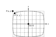
図4に示すように、テスト画像201上の座標P(x,y)(歪曲収差のない理想座標)に対し、撮像装置の出力画像202上の座標P´(x´,y´)は、歪曲収差の影響を受けてずれて結像される。この歪曲収差の影響は、光学レンズ系の焦点距離と、図4に示す画像の中心座標O(0,0)からその画像の任意の点までの距離とにより変化する。そこで、本実施形態では、図3に示すように、光学レンズ系の焦点距離と、テスト画像201上の座標P(x,y)と、撮像装置の出力画像202上の座標P(x´,y´)とをそれぞれ対応付けて、歪み補正座標記録部11に予め記録する。
FIG. 3 is a diagram illustrating an example of recorded contents recorded in the table 300 provided in the distortion correction coordinate
As shown in FIG. 4, the coordinates P ′ (x ′, y ′) on the
ところで、光学レンズ系における焦点距離と、撮像装置の出力画像202上の座標P(x´,y´)との全てについて、テスト画像201上の座標P(x,y)をテーブルに記録するようにすると、記録容量が大きくなってしまう。そこで、本実施形態では、所定の焦点距離毎(例えば図3に示すように5mm毎)に、テスト画像201上の座標P(x,y)と、撮像装置の出力画像202上の座標P(x´,y´)とをテーブル300に記録するようにしている。また、各焦点距離において、テスト画像201上の座標P(x,y)と、撮像装置の出力画像202上の座標P(x´,y´)とをそれぞれ3つずつテーブル300に記録するようにしている。なお、歪み補正座標記録部11に設けられているテーブル300は、例えば不図示のフラッシュメモリを用いることにより実現できる。
By the way, the coordinates P (x, y) on the
12は、歪補正後の画像信号を記録する画像記録部、13は輪郭抽出部である。14は、前フィールドの画像信号を記録する前フィールドメモリ、15は、現在の画像信号を記録する現フィールドメモリである。16は、動きベクトルを算出する動きベクトル演算部、17は、画面の切り出し制御を行うアドレス制御部である。
次に、本実施形態の撮像装置の動作の一例を説明する。
前述したように、光学レンズ系として、固定レンズ1と、変倍を行うズームレンズ2と、絞り3と、固定レンズ4と、焦点調整を行うフォーカスレンズ5とが光軸上に配置されており、被写体を撮像面に結像する。
Next, an example of the operation of the imaging apparatus according to the present embodiment will be described.
As described above, as the optical lens system, the fixed
撮像素子6は、光学レンズ系で撮像面に結像された被写体像を光電変換し画像信号を生成する。
アナログフロントエンド7は、撮像素子6から出力信号に含まれるリセットノイズを除去する相関二重サンプリングと、A/D変換とを行って、デジタル化した画像信号を生成し、歪補正回路8に出力する。
ズームエンコーダ9は、ズームレンズ2の位置を検出し、光学レンズ系の焦点距離を算出する。タイミングジュエネレータ10は、撮像素子6の読み出し位置を制御し、撮像素子6の読み出し位置情報を歪補正座標記録部11に出力する。
The
The analog
The
歪補正座標記録部11は、ズームエンコーダ9から、光学レンズ系の焦点距離を入力する。また、歪補正座標記録部11は、タイミングジュエネレータ10から、撮像素子6の読み出し位置を入力する。そして、歪補正座標記録部11は、入力した光学レンズ系の焦点距離と、撮像素子6の読み出し位置(図3及び図4に示した座標P´(x´、y´))とに対応するテスト画像201上の座標P(x,y)を、歪補正座標としてテーブル300から読み出す。そして、読み出した座標P(x,y)を歪補正部8に出力する。
The distortion correction coordinate
前述したように、本実施形態では、所定の焦点距離毎に、テスト画像201上の座標P(x,y)と、撮像装置の出力画像202上の座標P´(x´,y´)とをそれぞれ3つずつテーブル300に記録している。したがって、入力した光学レンズ系の焦点距離と、撮像素子6の読み出し位置とが、それぞれテーブル300に記録されている焦点距離と、座標P´(x´、y´)と一致するとは限らない。
As described above, in this embodiment, for each predetermined focal length, the coordinates P (x, y) on the
このような場合、本実施形態では、例えば、以下のようにして歪補正座標を取得するようにしている。
まず、歪補正座標記録部11は、入力した光学レンズ系の焦点距離よりも大きい焦点距離のうち、入力した光学レンズ系の焦点距離に最も近い焦点距離をテーブル300から読み出す。
そして、歪補正座標記録部11は、読み出した焦点距離に対応付けられてテーブル300に登録されている座標P´(x´,y´)のうち、撮像素子6の読み出し位置に最も近い座標P´(x´,y´)に対応付けられている歪補正座標P(x,y)を読み出す。
同様に、歪補正座標記録部11は、入力した光学レンズ系の焦点距離よりも小さい焦点距離のうち、入力した光学レンズ系の焦点距離に最も近い焦点距離をテーブル300から読み出す。
In such a case, in the present embodiment, for example, the distortion correction coordinates are acquired as follows.
First, the distortion correction coordinate
Then, the distortion correction coordinate
Similarly, the distortion correction coordinate
そして、歪補正座標記録部11は、読み出した焦点距離に対応付けられてテーブル300に登録されている座標P´(x´,y´)のうち、撮像素子6の読み出し位置に最も近い座標P´(x´,y´)に対応付けられている歪補正座標P(x,y)を読み出す。
歪補正座標記録部11は、以上のようにして読み出した2つの歪補正座標P(x,y)に対して補間処理を行い、撮像素子6の読み出し位置における歪補正座標P(x,y)を求めて、歪補正部8に出力する。
Then, the distortion correction coordinate
The distortion correction coordinate
なお、図3に示したテーブル300では、焦点距離の測定数nが所定数n0(nは自然数)個であり、焦点距離の測定間隔が5mmであり、各焦点距離におけるデータの数が3つの場合を例に挙げて示している。しかしながら、各焦点距離におけるデータの数や、焦点距離の設定等、テーブル300の設定方法は図3に示したものに限定されない。 In the table 300 shown in FIG. 3, the focal length measurement number n is a predetermined number n 0 (n is a natural number), the focal length measurement interval is 5 mm, and the number of data at each focal length is three. Two cases are shown as examples. However, the setting method of the table 300, such as the number of data at each focal length and the setting of the focal length, is not limited to that shown in FIG.
歪補正部8は、アナログフロントエンド7から出力された画像信号を、不図示のRAM等のメモリに一時的に記録する。このようにして一時的に記録された画像信号は、歪曲収差の影響を受けて歪んでいる。そこで、歪補正部8は、この歪曲収差の影響を受けて歪んでいる画像信号の座標が、歪補正座標記録部11から出力された歪補正座標に置き換わるように、メモリに一時的に記録した画像信号の読み出しアドレスを生成する。本実施形態の歪補正部8は、このようにして読み出しアドレスを、対応する歪補正座標に合わせて変えることによって、アナログフロントエンド7から出力された画像信号に生じている歪曲収差の影響を補正する。
以上のように、歪補正部8は、以上のような2次元の座標変換を行うことによって歪曲収差の影響を補正した画像信号を、画像記録部12及び輪郭抽出部13に出力する。
輪郭抽出部13は、歪補正部8から出力された画像信号を所定の閾値に応じて、「0」、又は「1」に2値化し、2値化した情報から画像信号における輪郭情報を抽出し、前フィールドメモリ14、及び現フィールドメモリ15に出力する。
The
As described above, the
The
図5は、動きベクトル演算部16のフィールドメモリへのアクセス領域の一例を示す図である。
前フィールドメモリ14は、図5(A)に示すように、1フィールド分だけ遅延した画面全体の画像信号501を記録している。現フィールドメモリ15は、図5(B)に示すように画面の一部の領域における画像信号502を記録する。ここで、図5(B)に示す画像信号502は、図5(F)に示す16個のブロックのうち、第1のブロック(図中1で示すブロック)の画像信号である。
動きベクトル演算部16は、前フィールドメモリ14に記録されている画像信号501から、この第1のブロック(画像信号502)の領域の大きさの画像信号503を切り出す(図5(C)を参照)。その後、動きベクトル演算部16は、第1のブロック(画像信号502)の領域の動きベクトルを算出するために、第1のブロック(画像信号502)の領域よりも広い範囲504を設定する。そして、設定した範囲504内で画像信号502、503の相関値を算出して第1のブロックにおける動きベクトルを求める。動きベクトル演算部16は、第2〜第16のブロックについても第1のブロックと同様の処理を行って第2〜第16のブロックの動きベクトルを順番に求め、求めた第1〜第16のブロックの動きベクトルを用いて画面全体の動きベクトルを求める。
FIG. 5 is a diagram illustrating an example of an access area to the field memory of the motion
As shown in FIG. 5A, the
The motion
図6は、動きベクトル検出の動作の一例を示すフローチャートである。なお、この例では、垂直同期信号の立ち下がりから次の立ち下がりまでの期間を1フィールド期間とし、1フィールド期間の最初に、図6のSTARTから動作する。 FIG. 6 is a flowchart illustrating an example of motion vector detection operation. In this example, the period from the falling edge of the vertical synchronizing signal to the next falling edge is defined as one field period, and the operation starts from START in FIG. 6 at the beginning of one field period.
図6のステップS1では、現フィールドメモリ15は、画面の一部の領域(図5(F)に示すブロックの何れか)の画像信号(例えば、第1のブロックの画像信号502)を記録する。
ステップS2では、動きベクトル演算部16は、前フィールドメモリ14に記録されている画像信号から、現フィールドメモリ15に記録された画像信号(例えば第1のブロックの画像信号502)の領域の大きさの画像信号(例えば画像信号503)を切り出す。そして、動きベクトル演算部16は、切り出した画像信号を読み出す。
In step S1 of FIG. 6, the
In step S <b> 2, the motion
次に、ステップS3では、動きベクトル演算部16は、ステップS1で現フィールドメモリ15に記録された画像信号を読み出し、現フィールドメモリ15から読み出した画像信号と、前フィールドメモリ14から読み出した画像信号とを比較する。そして、動きベクトル演算部16は、各画像信号の相関値を算出する。第1のブロックの動きベクトルを求める場合、動きベクトル演算部16は、画像信号502、503を比較し、図5(D)に示す矢印の方向に対する画像信号502、503の相関値を算出する。
Next, in step S3, the motion
次に、ステップS4では、動きベクトル演算部16は、前フィールドメモリ14から画像信号の切り出す位置を順次変化させる。すなわち、動きベクトル演算部16は、ステップS1で現フィールドメモリ15から読み出した画像信号よりも広い範囲であって、予め設定されている範囲について、ステップS2〜S4の処理を繰り返し行う。第1のブロックの動きベクトルを求める場合、図5(E)に示すように、動きベクトル演算部16は、予め設定されている範囲504について、ステップS2〜S4の処理を繰り返し行う。
Next, in step S <b> 4, the motion
そして、予め設定されている範囲について、ステップS2〜S4の処理を行うと、ステップS5に進み、動きベクトル演算部16は、ステップS3で算出した複数の相関値のうち、最も相関値が最も高いベクトルを、例えば不図示のRAMに記録する。
次に、ステップS6では、動きベクトル演算部16は、現フィールドメモリ15に記録する領域を変化させる指示を現フィールドメモリ15に対して行う。そして、動きベクトル演算部16は、図5(F)に示すようにして予め設定されている第1〜第16のブロックについて、ステップS1〜S6の処理を繰り返し行う。
And if the process of step S2-S4 is performed about the preset range, it will progress to step S5 and the motion
Next, in step S <b> 6, the motion
図5(F)に示すようにして予め設定されている第1〜第16のブロックについて、ステップS1〜S6の処理が終了するとステップS7に進む。ステップS7では、動きベクトル演算部16は、ステップS5で記録した各ブロックにおけるベクトル値を用いて、画面全体の動きベクトルを算出する。
なお、本実施形態では、16個のブロックについて動きベクトルを求めるようにしたが、ブロックの数は16個に限定されるものではないということは言うまでもない。
When the processes of steps S1 to S6 are completed for the first to sixteenth blocks set in advance as shown in FIG. 5F, the process proceeds to step S7. In step S7, the motion
In the present embodiment, motion vectors are obtained for 16 blocks, but it goes without saying that the number of blocks is not limited to 16.
アドレス制御部17は、動きベクトル演算部16で検出された動きベクトルに応じて画像記録部12から切り出す位置を制御する。すなわち、アドレス制御部17が、動きベクトル演算部16で検出された動きベクトルと逆方向に画面の切り出し位置を移動させることで、画像出力のぶれ(所謂手ぶれ)を補正する。
The
ここで、図7のフローチャートを参照しながら、図3に示したようなテーブル300を作成する際の動作の一例を説明する。なお、図7に示す動作は、外部の情報処理装置又は撮像装置に設けられ、装置全体を制御する不図示のCPUが、不図示のRAMをワークメモリとして使用しながら、プログラムを実行することにより実現することができる。
まず、ステップS11では、テーブル300における焦点距離の測定数nを1にセットする。次に、ステップS12では、第nの焦点距離におけるテスト画像201を取得し、ステップS13では、第nの焦点距離における撮像装置の出力画像202を取得する。
Here, an example of the operation when creating the table 300 as shown in FIG. 3 will be described with reference to the flowchart of FIG. The operation illustrated in FIG. 7 is performed by a CPU (not illustrated) that is provided in an external information processing apparatus or imaging apparatus and that controls the entire apparatus while using a RAM (not illustrated) as a work memory. Can be realized.
First, in step S11, the number n of focal length measurements in the table 300 is set to one. Next, in step S12, the
そして、ステップS14では、テスト画像201上の座標P(x,y)と、その座標P(x,y)に対応する、撮像装置の出力画像202上の座標P´(x´,y´)とを求める。
次に、ステップS15では、求めた座標P(x,y)、P´(x´,y´)と、第nの焦点距離とを対応付けてテーブル300に登録する。
次に、ステップS16では、焦点距離の測定数nが所定数n0であるか否かを判定する。すなわち、図3に示したように、n0個の焦点距離について、登録すべき座標P(x,y)、P´(x´,y´)を全て登録したか否かを判定する。この判定の結果、焦点距離の測定数nが所定数n0でない場合には、ステップS17に進む。ステップS17では、焦点距離の測定数nに1を加算する。そして、焦点距離の測定数nが所定数n0になるまで、ステップS12〜S17を繰り返し行う。
In step S14, the coordinates P (x, y) on the
Next, in step S15, the obtained coordinates P (x, y) and P ′ (x ′, y ′) are associated with the nth focal length and registered in the table 300.
Next, in step S16, it is determined whether or not the number n of focal length measurements is a predetermined number n 0 . That is, as shown in FIG. 3, it is determined whether or not all the coordinates P (x, y) and P ′ (x ′, y ′) to be registered have been registered for n 0 focal lengths. As a result of the determination, if the focal length measurement number n is not the predetermined number n 0 , the process proceeds to step S17. In step S17, 1 is added to the focal length measurement number n. Then, until the measurement number n of the focal length becomes a predetermined number n 0, it repeats the steps S12 to S17.
次に、図8のフローチャートを参照しながら、画像信号に生じている歪曲収差の影響を補正する際の歪補正座標記録部11及び歪補正部8の動作の一例について説明する。
まず、ステップS21では、歪補正座標記録部11は、ズームエンコーダ9から、光学レンズ系の焦点距離を入力するまで待機する。ズームエンコーダ9から、光学レンズ系の焦点距離が入力されると、ステップS22に進み、歪補正座標記録部11は、タイミングジュエネレータ10から、撮像素子6の読み出し位置を入力するまで待機する。なお、ステップS21、S22の順序は、逆であってもよい。
Next, an example of operations of the distortion correction coordinate
First, in step S21, the distortion correction coordinate
こうして光学レンズ系の焦点距離と、撮像素子6の読み出し位置とが入力されると、ステップS23に進む。ステップS23では、歪補正座標記録部11は、それら入力した光学レンズ系の焦点距離及び撮像素子6の読み出し位置が、それぞれテーブル300に登録されている焦点距離及び座標P´(x´,y´)と一致するか否かを判定する。この判定の結果、入力した光学レンズ系の焦点距離及び撮像素子6の読み出し位置が、それぞれテーブル300に登録されている焦点距離及び座標P´(x´,y´)と一致する場合には、ステップS24に進み、そうでない場合にはステップS25に進む。
When the focal length of the optical lens system and the reading position of the
ステップS24に進むと、歪補正座標記録部11は、テーブル300に登録されている焦点距離及び座標P´(x´,y´)に対応付けられている歪補正座標P(x,y)をテーブル300から読み出して、歪補正部8に出力する。
一方、ステップS25に進むと、歪補正記録部11は、前述したようにして補間処理を行い、その結果得られた補間値を、歪補正座標として歪補正部8に出力する。
In step S24, the distortion correction coordinate
On the other hand, when the process proceeds to step S25, the distortion
こうして歪補正座標が歪補正部8に出力されると、ステップS26に進む。ステップS26では、歪補正部8は、アナログフロントエンド7から出力された画像信号を不図示のRAM等のメモリに一時的に記録する。なお、このステップS26の処理は、ステップS24、S25よりも前に行ってもよい。
When the distortion correction coordinates are output to the
次に、ステップS27では、歪補正部8は、この歪曲収差の影響を受けて歪んでいる画像信号の座標が、ステップS24又はステップS25で出力された歪補正座標に置き換わるように、一時的に記録した画像信号の読み出しアドレスを生成する。そして、歪補正部8は、生成した読み出しアドレスに従って、一時的に記録した画像信号を読み出し、画像記録部12及び輪郭抽出部13に出力する。
次に、ステップS28では、歪補正座標記録部11は、タイミングジュエネレータ10から、撮像素子6の全ての読み出し位置が入力されたか否かを判定する。この判定の結果、撮像素子6の全ての読み出し位置が入力されていなければ、撮像素子6の全ての読み出し位置が入力されるまで、ステップS22〜ステップS28を繰り返し行う。
Next, in step S27, the
Next, in step S <b> 28, the distortion correction coordinate
以上のように本実施形態では、光学レンズ系の焦点距離と、テスト画像201上の座標P(x,y)と、撮像装置の出力画像202上の座標P(x´,y´)とをそれぞれ対応付けて、テーブル300に予め記録しておく。撮像が開始すると、歪補正座標記録部11は、ズームエンコーダ9から光学レンズ系の焦点距離を入力すると共に、タイミングジュエネレータ10から撮像素子6の読み出し位置を入力する。
As described above, in the present embodiment, the focal length of the optical lens system, the coordinates P (x, y) on the
そして、歪補正座標記録部11は、入力した光学レンズ系の焦点距離と、撮像素子6の読み出し位置と、テーブル300とを用いて、歪補正座標を取得して歪補正部8に出力する。歪補正部8は、この歪補正座標に合わせて、アナログフロントエンド7から出力された画像信号の読み出しアドレスを変えることにより画像信号に生じている歪曲収差の影響を補正する。そして、動きベクトル検出部16は、歪補正部8で光学レンズ系の歪曲収差の影響が補正された画像信号を用いて動きベクトルの検出を行う。
以上のように本実施形態では、光学レンズ系の歪曲収差の影響を補正した画像信号を用いて動きベクトルを検出するようにしたので、光学レンズ系の歪曲収差の影響による動きベクトルの検出の誤判定を可及的に防止することができる。これにより、動きベクトルの検出精度を向上させることができる。
Then, the distortion correction coordinate
As described above, in this embodiment, since the motion vector is detected using the image signal in which the influence of the distortion of the optical lens system is corrected, an error in detecting the motion vector due to the influence of the distortion of the optical lens system is detected. Judgment can be prevented as much as possible. Thereby, the detection accuracy of a motion vector can be improved.
なお、本実施形態では、光学レンズ系の歪曲収差の影響を補正した画像信号を用いて動きベクトルを検出し、検出した動きベクトルに応じてアドレス制御部17で、手ぶれを補正するようにしたが。検出した動きベクトルの利用方法はこれに限定されない。すなわち、動きベクトルを利用する処理であれば、必ずしも手ぶれを補正する必要はなく、例えばAF(Auto Focus)を行う測距エリアの変更を行うために動きベクトルを利用するようにしてもよい。このようにすることにより、測距エリアの変更を適切に行うことができる。この他、被写体の動きベクトルを検出するようにしてもよい。
In the present embodiment, the motion vector is detected using the image signal in which the influence of the distortion of the optical lens system is corrected, and the camera shake is corrected by the
(第2の実施形態)
次に、本発明の第2の実施形態について説明する。前述した第1の実施形態では、光学レンズ系が一体化された撮像装置で動きベクトルを正確に検出する場合について説明した。これに対し、本実施形態では、光学レンズ系を交換することが可能な撮像装置で動きベクトルを正確に検出するようにしている。すなわち、本実施形態は、光学レンズ系に歪曲収差を補正するための歪係数を記録しておき、この歪係数と画像信号の座標位置とを用いて演算で画像信号に生じている歪曲収差の影響を補正するものである。
(Second Embodiment)
Next, a second embodiment of the present invention will be described. In the first embodiment described above, the case has been described in which the motion vector is accurately detected by the imaging apparatus in which the optical lens system is integrated. On the other hand, in this embodiment, a motion vector is accurately detected by an imaging device that can exchange the optical lens system. That is, in this embodiment, a distortion coefficient for correcting distortion is recorded in the optical lens system, and the distortion aberration generated in the image signal is calculated by using the distortion coefficient and the coordinate position of the image signal. This is to correct the influence.
このように本実施形態と前述した第1の実施形態とは、光学レンズ系が取り外しできるか否かという点と、画像信号に生じている歪曲収差の影響を補正するためのデータの生成方法が主として異なる。したがって、本実施形態の説明において、第1の実施形態と同一部分については、図1〜図8に付した符号と同一の符号を付す等して詳細な説明を省略する。 As described above, the present embodiment and the first embodiment described above include a method for generating data for correcting whether the optical lens system can be removed and the influence of distortion occurring in the image signal. Mainly different. Therefore, in the description of the present embodiment, the same parts as those in the first embodiment are denoted by the same reference numerals as those in FIGS.
図9は、本実施形態の撮像装置の構成の一例を示す図である。図9に示すように、撮像装置701は、交換式レンズ702が取り付け可能になっている。
図9において、18は、歪係数を記録する歪係数記録部、19は、歪係数記録部18に記録されている歪係数と、画像信号の読み出し位置とを用いて、歪補正座標を算出する歪補正座標算出部である。20は、撮像装置側通信端子であり、21は、交換式レンズ側通信端子である。これら撮像装置側通信端子20及び交換式レンズ側通信端子21を介して、歪係数記録部18に記録されている歪係数が、歪補正座標算出部19に入力する。
FIG. 9 is a diagram illustrating an example of the configuration of the imaging apparatus according to the present embodiment. As shown in FIG. 9, the
In FIG. 9,
歪係数記録部18には、焦点距離に対応した歪係数が予め記録されている。歪係数記録部18は、例えば不図示のROMを用いることにより実現することができる。
In the distortion
ここで、歪係数記録部18に予め記録されている歪係数の算出方法の一例について説明する。
まず、工場での製品組み立て時に、図2(A)に示したようなテスト画像201を撮影する。そして、撮影したテスト画像201と、図2(B)に示したような撮像装置の出力画像202とを用いて、焦点距離に対応する歪係数を算出する。
Here, an example of a method for calculating a distortion coefficient recorded in advance in the distortion
First, when assembling a product in a factory, a
図10は、光学中心に対応するテスト画像201の中心から、テスト画像201上の任意の点の座標までの距離と、光学中心に対応するテスト画像201から、撮像装置の出力画像202上の任意の点の座標までの距離との一例を示す図である。
図10において、光学中心に対応するテスト画像201の座標をO(0,0)としている。また、歪曲収差のない理想座標として、テスト画像201上の任意の点の座標をP(x、y)としている。さらに、歪曲収差によって歪んでいる座標として、撮像装置の出力画像202上の任意の点の座標をP´(x'、y')としている。また、光学中心に対応するテスト画像201の中心から、テスト画像201上の任意の点の座標までの距離をrとし、光学中心に対応するテスト画像201の中心から、撮像装置の出力画像202上の任意の点の座標までの距離をr´としている。
FIG. 10 illustrates the distance from the center of the
In FIG. 10, the coordinates of the
ここで、撮像装置の出力画像202上の座標P´(x'、y')での歪み率D(r)[%)は、式(1)で表される。
D(r)=(r'−r)/r×100 ・・・(1)
歪曲収差は、光学中心O(0,0)からの距離が離れるほど影響を受け、光学レンズ系の焦点距離により特性が変化する。
一般に歪み率D(r)は、光学中心に対応するテスト画像201の中心から、テスト画像201上の任意の点の座標までの距離rの2乗に比例するので、α、βを焦点距離により決定する定数とすると、歪み率D(r)は、式(2)のように近似できる。
D(r)=α×r2 ・・・(2)
また、焦点距離による定数α、βの関係を式(3)とする。
β =100α ・・・(3)
Here, the distortion rate D (r) [%] at the coordinates P ′ (x ′, y ′) on the
D (r) = (r′−r) / r × 100 (1)
The distortion is affected as the distance from the optical center O (0, 0) increases, and the characteristic changes depending on the focal length of the optical lens system.
In general, since the distortion rate D (r) is proportional to the square of the distance r from the center of the
D (r) = α × r 2 (2)
Further, the relationship between the constants α and β depending on the focal length is represented by Expression (3).
β = 100α (3)
式(1)、(2)、(3)より、光学中心から撮像装置の出力画像202上の座標までの距離r'は式(4)で表される。
r'=r(1+β・r2 ) ・・・(4)
式(4)より、撮像装置の出力画像202上の座標P´(x'、y')は、テスト画像201上の座標P(x、y)よりも、(1+β・r2)倍、光学中心に対応するテスト画像201の座標O(0,0)から離れていると考えられる。したがって、水平、垂直方向の距離も(1+β・r2)倍離れていることとなる。
From Expressions (1), (2), and (3), the distance r ′ from the optical center to the coordinates on the
r ′ = r (1 + β · r 2 ) (4)
From the equation (4), the coordinate P ′ (x ′, y ′) on the
式(4)より、撮像装置の出力画像202上の座標P´(x'、y')と、テスト画像201上の座標P(x、y)との関係は、式(5)、(6)で表される。
x'=x(1+β・r2 )=x{1+β・(x2 +y2 )} ・・・(5)
y'=y(1+β・r2 )=y{1+β・(x2 +y2 )} ・・・(6)
テスト画像201と、撮像装置の出力画像202と、式(5)、(6)とを用いることにより、歪係数βが算出される。このような歪係数βは、焦点距離毎に算出される。そして、算出された焦点距離と歪係数βとが対応付けられたテーブルが、歪係数記録部18に予め記録される。
図11は、歪係数記録部18に設けられているテーブル1100に記録される記録内容の一例を示す図である。図11に示すように、本実施形態では、所定の焦点距離毎(例えば図11に示すように5mm毎)に、焦点距離と、歪係数βとをテーブル1100に記録するようにしている。光学レンズ系における全ての焦点距離について、歪係数βを記録するようにすると、記録容量が大きくなってしまうからである。なお、歪係数記録部18に設けられているテーブル1100は、例えば不図示のフラッシュメモリを用いることにより実現できる。
From Expression (4), the relationship between the coordinates P ′ (x ′, y ′) on the
x ′ = x (1 + β · r 2 ) = x {1 + β · (x 2 + y 2 )} (5)
y ′ = y (1 + β · r 2 ) = y {1 + β · (x 2 + y 2 )} (6)
The distortion coefficient β is calculated by using the
FIG. 11 is a diagram showing an example of recorded contents recorded in the table 1100 provided in the distortion
タイミングジュエネレータ10は、撮像素子6の読み出し位置情報を歪補正座標算出部19に出力する。
歪補正座標算出部19は、歪係数βを取得するために歪係数要求信号を、撮像装置側通信端子20及び交換式レンズ側通信端子21を介して、歪係数記録部18に送信する。そうすると、歪係数記録部18は、光学レンズ系の焦点距離に対応した歪係数βを歪係数記録部18から読み出して、撮像装置側通信端子20及び交換式レンズ側通信端子21を介して、歪補正座標算出部19に出力する。
The
The distortion correction coordinate
歪補正座標算出部19は、歪係数記録部18から出力された歪係数βと、タイミングジュエネレータ10から出力された読み出し位置情報とを式(5)、(6)に代入して、歪補正座標P(x、y)を算出し、歪補正部8に出力する。
The distortion correction coordinate
前述したように、本実施形態では、所定の焦点距離毎に歪係数βをテーブル1100に記録している。したがって、入力した光学レンズ系の焦点距離が、それぞれテーブル1100に記録されている焦点距離と一致するとは限らない。 As described above, in this embodiment, the distortion coefficient β is recorded in the table 1100 for each predetermined focal length. Therefore, the focal length of the input optical lens system does not always match the focal length recorded in the table 1100.
このような場合、本実施形態では、以下のようにして歪係数βを取得するようにしている。
まず、歪係数記録部18は、歪補正座標算出部19から歪係数要求信号を入力すると、入力した光学レンズ系の焦点距離よりも大きい焦点距離のうち、入力した光学レンズ系の焦点距離に最も近い焦点距離をテーブル1100から読み出す。そして、歪係数記録部18は、読み出した焦点距離と、その焦点距離に対応付けられてテーブル1100に登録されている歪係数βとを読み出す。
In such a case, in the present embodiment, the distortion coefficient β is obtained as follows.
First, when a distortion coefficient request signal is input from the distortion correction coordinate
同様に、歪係数記録部18は、入力した光学レンズ系の焦点距離よりも小さい焦点距離のうち、入力した光学レンズ系の焦点距離に最も近い焦点距離をテーブル1100から読み出す。そして、歪係数記録部18は、読み出した焦点距離と、その焦点距離に対応付けられてテーブル1100に登録されている歪係数βとを読み出す。
Similarly, the distortion
歪係数記録部18は、以上のようにして読み出した2つの歪係数βを用いて補間処理を行い、その結果得られた歪係数βを、歪補正座標算出部19に出力する。
なお、図11に示したテーブル1100では、焦点距離の測定数nが所定数n1(nは自然数)個であり、焦点距離の測定間隔が5mmである場合を例に挙げて示しているが、焦点距離の設定は図11に示したものに限定されない。
The distortion
In the table 1100 shown in FIG. 11, the number n of focal lengths is a predetermined number n 1 (n is a natural number), and the focal length measurement interval is 5 mm as an example. The setting of the focal length is not limited to that shown in FIG.
歪補正部8は、アナログフロントエンド7から出力された画像信号を不図示のRAM等のメモリに一時的に記録する。このようにして一時的に記録された画像信号は、歪曲収差の影響を受けて歪んでいる。そこで、歪補正部8は、この歪曲収差の影響を受けて歪んでいる画像信号の座標が、歪補正座標算出部19から出力された歪補正座標に置き換わるように、不図示のRAM等のメモリに一時的に記録した画像信号の読み出しアドレスを生成する。歪補正部8は、このようにして読み出しアドレスを、対応する歪補正座標に合わせて変えることによって、アナログフロントエンド7から出力された画像信号に生じている歪曲収差の影響を補正する。そして、歪補正部8は、歪曲収差の影響を補正した画像信号を、画像記録部12及び輪郭抽出部13に出力する。
The
ここで、図12のフローチャートを参照しながら、図11に示したようなテーブル1100を作成する際の動作の一例を説明する。なお、図12に示す動作は、例えば、外部の情報処理装置又は撮像装置に設けられ、装置全体を制御する不図示のCPUが、不図示のRAMをワークメモリとして使用しながら、プログラムを実行することにより実現することができる。
まず、ステップS31では、テーブル1100における焦点距離の測定数nを1にセットする。次に、ステップS32では、第nの焦点距離におけるテスト画像201を取得し、ステップS33では、第nの焦点距離における撮像装置の出力画像202を取得する。
Here, an example of an operation when creating the table 1100 as shown in FIG. 11 will be described with reference to the flowchart of FIG. The operation illustrated in FIG. 12 is provided in, for example, an external information processing apparatus or imaging apparatus, and a CPU (not illustrated) that controls the entire apparatus executes a program while using a RAM (not illustrated) as a work memory. Can be realized.
First, in step S31, the number n of focal length measurements in the table 1100 is set to one. Next, in step S32, the
そして、ステップS34では、テスト画像201上の座標P(x,y)と、その座標P(x,y)に対応する、撮像装置の出力画像202上の座標P´(x´,y´)とを求める。
次に、ステップS35では、求めた座標P(x,y)、P´(x´,y´)を、式(5)、式(6)に代入して、歪係数βを算出する。
次に、ステップS36では、歪係数βと、第nの焦点距離とを対応付けてテーブル1100に登録する。
次に、ステップS37では、焦点距離の測定数nが所定数n1であるか否かを判定する。すなわち、図11に示したように、テーブル1100に登録すべき全ての焦点距離について、歪係数βを登録したか否かを判定する。この判定の結果、焦点距離の測定数nが所定数n1でない場合には、ステップS38に進む。ステップS38では、焦点距離の測定数nに1を加算する。そして、焦点距離の測定数nが所定数n1になるまで、ステップS32〜S38を繰り返し行う。
In step S34, the coordinates P (x, y) on the
Next, in step S35, the obtained coordinates P (x, y) and P ′ (x ′, y ′) are substituted into equations (5) and (6) to calculate the distortion coefficient β.
Next, in step S36, the distortion coefficient β and the nth focal length are associated with each other and registered in the table 1100.
Next, in step S37, it is determined whether or not the number n of focal length measurements is a predetermined number n 1 . That is, as shown in FIG. 11, it is determined whether or not the distortion coefficient β has been registered for all focal lengths to be registered in the table 1100. As a result of the determination, if the focal length measurement number n is not the predetermined number n 1 , the process proceeds to step S38. In step S38, 1 is added to the focal length measurement number n. Then, steps S32 to S38 are repeated until the focal length measurement number n reaches the predetermined number n 1 .
次に、図13のフローチャートを参照しながら、歪補正座標を算出して画像信号に生じている歪曲収差の影響を補正する際の歪係数記録部18、歪補正座標算出部19、及び歪補正部8の動作の一例について説明する。
まず、ステップS41では、歪補正座標算出部19は、タイミングジュエネレータ10から、撮像素子6の読み出し位置を入力するまで待機する。次に、ステップS42では、歪補正座標算出部19は、歪係数要求信号を歪係数記録部18に送信する。
次に、ステップS43では、歪係数記録部18は、入力した光学レンズ系の焦点距離が、テーブル1100に登録されている焦点距離と一致するか否かを判定する。この判定の結果、入力した光学レンズ系の焦点距離が、テーブル1100に登録されている焦点距離と一致する場合には、ステップS44に進み、そうでない場合にはステップS45に進む。
Next, referring to the flowchart of FIG. 13, the distortion
First, in step S <b> 41, the distortion correction coordinate
Next, in step S <b> 43, the distortion
ステップS44に進むと、歪係数記録部18は、テーブル1100に登録されている焦点距離に対応付けられている歪係数βを、テーブル1100から読み出して、歪補正座標算出部19に出力する。
一方、ステップS45に進むと、歪係数記録部18は、前述したようにして補間処理を行い、その結果得られた補間値を、歪係数βとして歪補正座標算出部19に出力する。
In
On the other hand, when the process proceeds to step S45, the distortion
こうして歪係数βが歪補正座標算出部19に出力されると、ステップS46に進む。ステップS46では、歪補正座標算出部19は、入力した撮像素子6の読み出し位置と、歪係数記録部18から出力された歪係数βとを式(5)、(6)に代入して、歪補正座標P(x、y)を算出して歪補正部8に出力する。
次に、ステップS47では、歪補正部8は、アナログフロントエンド7から出力された画像信号を不図示のRAM等のメモリに一時的に記録する。なお、このステップS47の処理は、ステップS46よりも前に行ってもよい。
When the distortion coefficient β is output to the distortion correction coordinate
Next, in step S47, the
次に、ステップS48では、歪補正部8は、この歪曲収差の影響を受けて歪んでいる画像信号の座標が、ステップS46で算出された歪補正座標P(x、y)に置き換わるように、一時的に記録した画像信号の読み出しアドレスを生成する。そして、歪補正部8は、生成した読み出しアドレスに従って、一時的に記録した画像信号を読み出し、画像記録部12及び輪郭抽出部13に出力する。
次に、ステップS49では、歪補正座標算出部19は、タイミングジュエネレータ10から、撮像素子6の全ての読み出し位置が入力されたか否かを判定する。この判定の結果、撮像素子6の全ての読み出し位置が入力されていなければ、撮像素子6の全ての読み出し位置が入力されるまで、ステップS41〜ステップS49を繰り返し行う。
Next, in step S48, the
Next, in step S <b> 49, the distortion correction coordinate
以上のように本実施形態では、光学レンズ系の歪係数βと、撮像素子6の読み出し位置と、式(5)、(6)とを用いて、歪補正座標P(x,y)を算出するようにした。したがって、図3に示したように、全ての読み出し位置に対応した歪補正座標P(x,y)を記録する場合に比べて、小さな容量の記録媒体で歪補正座標を取得することが可能となる(図11を参照)。
また、光学レンズ系自体に歪曲収差の情報を持たせているため、交換レンズ式のデジタルビデオカメラにおいても使用するレンズに対応した歪補正を行うことができる。
As described above, in the present embodiment, the distortion correction coordinate P (x, y) is calculated using the distortion coefficient β of the optical lens system, the reading position of the
In addition, since distortion information is provided in the optical lens system itself, distortion correction corresponding to a lens used in an interchangeable lens type digital video camera can be performed.
なお、本実施形態では、歪係数記録部18を交換式レンズ702に設けるようにしたが、歪係数記録部18を撮像装置701に設けるようにしてもよい。
また、本実施形態では、交換式レンズ702が撮像装置701に取り付けられる構成を例に挙げて説明したが、第1の実施形態のように、光学レンズ系が一体化された撮像装置であっても本実施形態で説明した歪係数βを用いた歪曲収差の補正を行うことができる。このようにする場合には、例えば、図9に示した構成において、光学レンズ系と歪係数記録部18とを撮像装置701に設けるようにすればよい。
In this embodiment, the distortion
Further, in the present embodiment, the configuration in which the
また、本実施形態では、歪係数記録部18で補間処理を行うようにしたが、歪補正座標算出部19で補間処理を行うようにしてもよい。
さらに、本実施形態のような光学レンズ系を交換することが可能な撮像装置であっても、前述した第1の本実施形態を実現することができる。このようにする場合には、例えば、図9に示した構成において、歪係数記録部18の代わりに図3に示したテーブル300を設け、歪補正座標算出部19の代わりに歪補正座標記録部11における処理機能(テーブル300以外の構成)を設けるようにすればよい。
Further, in the present embodiment, the interpolation processing is performed by the distortion
Furthermore, even the imaging apparatus capable of exchanging the optical lens system as in this embodiment can realize the first embodiment described above. In this case, for example, in the configuration shown in FIG. 9, the table 300 shown in FIG. 3 is provided instead of the distortion
(第3の実施形態)
次に、本発明の第3の実施形態について説明する。前述した第1及び第2の実施形態では、動きベクトルを求める際に歪補正部8で画面全体に生じている歪曲収差の影響を補正するようにした。これに対し、本実施形態では、動きベクトルを検出するための現フィールドメモリで必要となる領域についてのみ、歪曲収差の影響を補正するようにしている。すなわち、本実施形態は、現フィールドメモリで必要となる領域についてのみ歪曲収差の影響を補正する第2の歪補正部22を用いることにより、撮像素子6に結像されてから動きベクトルの値が検出されるまでの時間を短縮するものである。また、本実施形態では、動きベクトルの検出結果をフィードバッグして光学的に振れを補正するようにしている。
(Third embodiment)
Next, a third embodiment of the present invention will be described. In the first and second embodiments described above, the
このように本実施形態と前述した第1及び第2の実施形態とは、歪曲収差の影響を補正する方法と、動きベクトルの検出結果の利用方法と、撮像装置の振れの補正方法とが主として異なる。したがって、本実施形態の説明において、第1の実施形態と同一部分については、図1〜図8に付した符号と同一の符号を付す等して詳細な説明を省略する。 As described above, the present embodiment and the first and second embodiments described above mainly include a method for correcting the influence of distortion, a method for using a motion vector detection result, and a method for correcting a shake of an imaging apparatus. Different. Therefore, in the description of the present embodiment, the same parts as those in the first embodiment are denoted by the same reference numerals as those in FIGS.
本実施形態の説明を行う前に、本実施形態の撮像装置との対比として、まず、前述した第1の実施形態の撮像装置における動きベクトル検出動作について説明する。
図14は、第1の実施形態の撮像装置の動作タイミングの一例を示す図である。
図14において、垂直同期信号の立ち下がりから次の立ち下がりまでの期間を1フィールド期間として、現在のフィールドをF0、1フィールド前をF−1、1フィールド後をF1として説明する。
Before describing the present embodiment, as a comparison with the imaging apparatus of the present embodiment, first, a motion vector detection operation in the imaging apparatus of the first embodiment will be described.
FIG. 14 is a diagram illustrating an example of operation timing of the imaging apparatus according to the first embodiment.
In FIG. 14, the period from the fall of the vertical synchronizing signal to the next fall is defined as one field period, the current field is F0, the field before F is F-1, and the field after is F1.
図14(A)に撮像素子6の出力を示す。撮像素子6からは1フィールド期間に1画面分の画像信号が読み出され、アナログフロントエンド7でデジタル化されて歪補正部8に出力される。ここで、現在のフィールドで読み出される画像信号を0、1フィールド前に読み出された画像信号を−1、1フィールド後に読み出される画像信号を1とする。
FIG. 14A shows the output of the
図14(B)に歪補正部8の出力を示す。
歪補正部8では、撮像素子6の全画面領域を歪補正するため、1フィールドの歪補正処理時間が必要となる。
このため、図14(B)に示すように、歪補正部8は、撮像素子6の出力よりも1フィールド遅れた画像信号を出力する。
図14(C)に前フィールドメモリ14の出力を示す。
前フィールドメモリ14では、入力信号に対して1フィールドの遅延を持たせているため、図14(C)に示すように、前フィールドメモリ18は、撮像素子6から2フィールド遅れた画像信号を出力する。
FIG. 14B shows the output of the
The
Therefore, as shown in FIG. 14B, the
FIG. 14C shows the output of the
Since the
図14(D)に動きベクトルの検出タイミングを示す。
ここでは、矢印の左側に示す数字(図14では「−1」)が示すフィールド(フィールドF−1)と、矢印の右側に示す数字(図14では「0」)が示すフィールド(フィールドF0)との間の動きベクトルを検出することを示している。
FIG. 14D shows the motion vector detection timing.
Here, the field (field F-1) indicated by the number shown on the left side of the arrow ("-1" in FIG. 14) and the field (field F0) indicated by the number shown on the right side of the arrow ("0" in FIG. 14). It shows that the motion vector between is detected.
動きベクトル演算部16は、図14(B)に示した歪補正部8の出力信号を現在のフィールド、図14(C)に示した前フィールドメモリ18の出力信号を1フィールド前の信号として動きベクトルの検出を行っている。
このため、現在のフィールド期間であるフィールドF0において発生した動きベクトル"−1→0"は、次のフィールドであるフィールドF1になって検出されることになる。この結果、第1の実施形態の撮像装置では、動きベクトル検出結果をフィードバッグして処理を行う場合、応答速度が低下する不都合があった。そこで、本実施形態では、このような不都合を解消するようにした。以下に、本実施形態の撮像装置について説明する。
The motion
For this reason, the motion vector “−1 → 0” generated in the
図15は、本実施形態の撮像装置の構成の一例を示す図である。
図15において、22は第2の歪補正部、23は第2の輪郭抽出部である。24は可変頂角プリズム(以下VAPと称する)、25はVAP制御部である。なお、第1の歪補正部8及び第1の輪郭抽出部13は、それぞれ図1に示した歪補正部8及び輪郭抽出部13と同じものである。
FIG. 15 is a diagram illustrating an example of the configuration of the imaging apparatus according to the present embodiment.
In FIG. 15, 22 is a second distortion correction unit, and 23 is a second contour extraction unit.
第2の歪補正部22には、第1の歪補正部8と同様に、アナログフロントエンド7でデジタル化された画像信号と、歪補正記録部11から読み出された歪補正座標P(x,y)とが入力される。
その後、第2の歪補正部22は、第1の歪補正部8と同様に、アナログフロントエンド7から入力した画像信号を不図示のRAM等のメモリに一時的に記録する。そして、第2の歪補正部20は、このメモリに一時的に記録された画像信号の座標が、歪補正座標記録部11から入力した歪補正座標P(x,y)に置き換わるように、RAM等のメモリに一時的に記録した画像信号の読み出しアドレスを生成する。
Similar to the first
Thereafter, like the first
このようにして読み出しアドレスを、対応する歪補正座標P(x,y)に合わせて変えることによって、第2の歪補正部22は、アナログフロントエンド7から出力された画像信号に生じている歪曲収差の影響を補正する。そして、第2の歪補正部22は、以上のような2次元の座標変換を行うことによって歪曲収差の影響を補正した画像信号を、第2の輪郭抽出部23に出力する。
In this way, by changing the read address in accordance with the corresponding distortion correction coordinates P (x, y), the second
第2の輪郭抽出部23は、第2の歪補正部22から出力された画像信号を、所定の閾値に応じて「0」、又は「1」に2値化し、2値化した情報から画像信号における輪郭情報を抽出し、現フィールドメモリ15に出力する。
ここで、第1の歪補正部8の出力は、画像出力として使用される画像信号である。このため、第1の歪補正部8は、画像の全領域の歪補正を行う必要がある。
The second
Here, the output of the first
これに対し、第2の歪補正部22は、動きベクトルの検出に使用する現フィールドメモリ15で必要となる領域における画像信号(例えば、図5(B)に示した画面の一部の領域における画像信号502)を順番に補正する。すなわち、第2の歪補正部22は、図5(F)に示した各ブロックについて順番に画像信号を補正する。そして、動きベクトル演算部16は、第2の歪補正部22で画像信号が補正された各ブロックについて順番に動きベクトルを算出する。
On the other hand, the second
前述したような2次元の座標変換による歪補正の処理時間は補正画素数に比例する。このため、第2の歪補正部22は、第1の歪補正部8よりも短時間で歪補正を行うことができる。
以上のように本実施形態では、第1の歪補正部8からの画像信号を1フィールド前の画像信号とし、第2の歪補正部22からの画像信号を現在のフィールドの画像信号として動きベクトルの検出を行う。
The distortion correction processing time by two-dimensional coordinate transformation as described above is proportional to the number of correction pixels. For this reason, the second
As described above, in this embodiment, the image signal from the first
VAP制御部25は、動きベクトル演算部16で検出された画像信号の動きベクトルに基づいてVAP制御信号を生成する。VAP22は、VAP制御信号に応じて頂角を可変することにより光学的に振れを補正する。
The
図15と図16を用いて本実施形態の撮像装置における動きベクトルの検出動作について説明する。図16は、本実施形態の撮像装置の動作タイミングの一例を示す図である。
図14と同様に、図16においても、垂直同期信号の立ち下がりから次の立ち下がりまでの期間を1フィールド期間として、現在のフィールドをF0、1フィールド前をF−1、1フィールド後をF1として説明する。
A motion vector detection operation in the imaging apparatus of the present embodiment will be described with reference to FIGS. 15 and 16. FIG. 16 is a diagram illustrating an example of operation timing of the imaging apparatus according to the present embodiment.
Similarly to FIG. 14, in FIG. 16, the period from the falling edge of the vertical synchronizing signal to the next falling edge is defined as one field period, the current field is F0, the field before F-1 is, and the field after F1 is F1. Will be described.
図16(A)に撮像素子6の出力を示す。撮像素子6からは1フィールド期間に1画面分の画像信号が読み出され、アナログフロントエンド7でデジタル化され第1及び第2の歪補正部8、22に出力される。ここで、現在のフィールドで読み出される画像信号を「0」、1フィールド前に読み出された画像信号を「−1」、1フィールド後に読み出される画像信号を「1」とする。
図16(B)に第2の歪補正部20の出力を示す。
第2の歪補正部22は、アナログフロントエンド7から入力される画像信号に対して、現フィールドメモリ15で必要となる画素領域のみの歪補正を行う。
ここで、第2の歪補正部22は、歪補正する画素領域を小さくすることによって、撮像素子6の出力と同一のフィールドで画像信号を第2の輪郭抽出部23に出力することができる。
FIG. 16A shows the output of the
FIG. 16B shows the output of the second
The second
Here, the second
図16(C)に第1の歪補正部8の出力を示す。
第1の歪補正部8では画像の全領域を歪補正する。このため、1フィールドの歪補正処理時間が必要となる。
図16(D)に動きベクトルの検出タイミングを示す。
ここでは、矢印の左側に示す数字が示すフィールドと、矢印の右側に示す数字が示すフィールドとの間の動きベクトルを検出することを示している。
FIG. 16C shows the output of the first
The first
FIG. 16D shows the motion vector detection timing.
Here, the motion vector between the field indicated by the number shown on the left side of the arrow and the field indicated by the number shown on the right side of the arrow is detected.
動きベクトル演算部16は、図16(B)に示した第2の歪補正部22からの出力信号を現在のフィールドの信号とし、図16(C)に示した第1の補正部8からの出力信号を1フィールド前の信号として動きベクトルの検出を行っている。
このため、現在のフィールド期間であるフィールドF0において発生した動きベクトル"0→1"を現在のフィールドF0で検出する。この結果、動きベクトルの検出結果をフィードバッグする場合でも応答速度の良い制御を行うことができる。
The motion
Therefore, the motion vector “0 → 1” generated in the field F0 which is the current field period is detected in the current field F0. As a result, even when a motion vector detection result is fed back, control with a good response speed can be performed.
なお、本実施形態は、第1の実施形態のように歪補正座標を歪補正座標記録部11に記録する場合だけでなく、第2の実施形態のように歪係数βを用いて歪補正座標を歪補正座標算出部19で算出する場合にも適用することができる。
また、本実施形態において、第1の実施形態及び第2の実施形態のように画面の切り出し位置を変えて振れを補正する構成としてもよい。さらに、応答速度が遅くなる虞があるが、第1の実施形態及び第2の実施形態において、本実施形態のように光学的に振れを補正する構成としてもよい。
In the present embodiment, not only when the distortion correction coordinates are recorded in the distortion correction coordinate
In the present embodiment, as in the first embodiment and the second embodiment, the shake may be corrected by changing the cutout position of the screen. Furthermore, there is a possibility that the response speed may be slow, but in the first embodiment and the second embodiment, it may be configured to optically correct shake as in the present embodiment.
(本発明の他の実施形態)
前述の実施形態の機能を実現するべく各種のデバイスを動作させるように、該各種デバイスと接続された装置又はシステム内のコンピュータに対し、前述の機能を実現するためのソフトウェアのプログラムコードを供給するものも、本発明の範疇に含まれる。そして、そのシステム又は装置のコンピュータ(CPUあるいはMPU)に格納されたプログラムに従って各種デバイスを動作させることによって実施したものも、本発明の範疇に含まれる。
(Other embodiments of the present invention)
In order to operate various devices to realize the functions of the above-described embodiments, program codes of software for realizing the above-described functions are supplied to an apparatus or a computer in the system connected to the various devices. Are also included in the scope of the present invention. And what was implemented by operating various devices according to the program stored in the computer (CPU or MPU) of the system or apparatus is also included in the category of the present invention.
また、この場合、ソフトウェアのプログラムコード自体が前述の実施形態の機能を実現することになる。そして、そのプログラムコード自体、及びそのプログラムコードをコンピュータに供給するための手段、例えば、かかるプログラムコードを格納した記録媒体は本発明を構成する。かかるプログラムコードを記憶する記録媒体としては、例えばフレキシブルディスク、ハードディスク、光ディスク、光磁気ディスク、CD−ROM、磁気テープ、不揮発性のメモリカード、ROM、DVD等を用いることができる。 In this case, the software program code itself realizes the functions of the above-described embodiments. The program code itself and means for supplying the program code to the computer, for example, a recording medium storing the program code constitute the present invention. As a recording medium for storing such a program code, for example, a flexible disk, a hard disk, an optical disk, a magneto-optical disk, a CD-ROM, a magnetic tape, a nonvolatile memory card, a ROM, a DVD, or the like can be used.
また、プログラムコードがコンピュータにおいて稼働しているOS(オペレーティングシステム)あるいは他のアプリケーションソフト等と共同して前述の実施形態の機能が実現される場合にもかかるプログラムコードは本発明の実施形態に含まれる。 The program code is also included in the embodiment of the present invention when the function of the above-described embodiment is realized in cooperation with an OS (operating system) or other application software running on the computer. It is.
さらに、供給されたプログラムコードをコンピュータの機能拡張ボードやコンピュータに接続された機能拡張ユニットに備わるメモリに格納する。その後、そのプログラムコードの指示に基づいてその機能拡張ボードや機能拡張ユニットに備わるCPU等が実際の処理の一部または全部を行い、その処理によって上述した実施形態の機能が実現される場合にも本発明に含まれることは言うまでもない。 Further, the supplied program code is stored in a memory provided in a function expansion board of the computer or a function expansion unit connected to the computer. Thereafter, the CPU or the like provided in the function expansion board or function expansion unit performs part or all of the actual processing based on the instruction of the program code, and the functions of the above-described embodiments are realized by the processing. It goes without saying that it is included in the present invention.
なお、前述の実施形態は、何れも本発明を実施するにあたっての具体化の例を示したものに過ぎず、これらによって本発明の技術的範囲が限定的に解釈されてはならないものである。すなわち、本発明はその技術思想、またはその主要な特徴から逸脱することなく、様々な形で実施することができる。 It should be noted that the above-described embodiments are merely examples of implementation in carrying out the present invention, and the technical scope of the present invention should not be construed in a limited manner. That is, the present invention can be implemented in various forms without departing from the technical idea or the main features thereof.
1、4 固定レンズ
2 ズームレンズ
3 絞り
5 フォーカスレンズ
6 撮像素子
7 アナログフロントエンド
8 歪補正部
9 ズームエンコーダ
10 タイミングジェネレータ
11 歪補正座標記録部
12 画像記録部
13、21 輪郭抽出部
14 前フィールドメモリ
15 現フィールドメモリ
16 動きベクトル演算部
17 アドレス制御部
18 歪係数記録部
19 歪補正座標算出部
20 撮像装置側通信端子
21 交換式レンズ側通信端子
22 第2の歪補正部
23 第2の輪郭抽出部
24 可変頂角プリズム(VAP)
25 VAP制御部
DESCRIPTION OF
25 VAP controller
Claims (12)
前記光学レンズの歪曲収差を補正するための歪曲収差補正用データを算出する算出手段と、
前記算出手段によって算出された歪曲収差補正用データに基づいて、前記撮像素子により電気信号に変換された被写体像に基づく画像に対して前記光学レンズの歪曲収差を補正する歪補正手段と、
前記歪補正手段により前記歪曲収差が補正された画像を用いて動きベクトルの検出を行う動きベクトル検出手段と、
前記動きベクトルの検出に基づいて動きを補正する動き補正手段とを有し、
前記歪補正手段は、動きベクトルの検出に必要な領域のみ前記光学レンズの歪曲収差を補正することを特徴とする撮像装置。 An image sensor that converts an object image formed by an optical lens that forms an image on an imaging surface into an electrical signal; and
Calculation means for calculating distortion correction data for correcting distortion of the optical lens;
Distortion correction means for correcting distortion aberration of the optical lens with respect to an image based on a subject image converted into an electrical signal by the imaging device based on distortion aberration correction data calculated by the calculation means;
A motion vector detection means for detecting a motion vector using an image in which the distortion is corrected by the distortion correction means;
Motion correction means for correcting motion based on the detection of the motion vector ,
The image pickup apparatus , wherein the distortion correction unit corrects distortion aberration of the optical lens only in a region necessary for detecting a motion vector .
前記算出手段は、前記歪曲収差補正用データを、前記交換式レンズ装置が有している前記テーブルの情報を用いて算出することを特徴とする請求項2乃至4の何れか1項に記載の撮像装置。 Further comprising communication means for communicating with the interchangeable lens device having the table;
The calculating means, the pre Kiibitsu songs aberration correction data, to any one of claims 2 to 4, characterized in that calculated using the information of the table in which the interchangeable lens unit has The imaging device described.
前記光学レンズの歪曲収差を補正するための歪曲収差補正用データを算出する算出手段と、Calculation means for calculating distortion correction data for correcting distortion of the optical lens;
前記算出手段によって算出された歪曲収差補正用データに基づいて、前記撮像素子により電気信号に変換された被写体像に基づく画像に対して前記光学レンズの歪曲収差を補正する歪補正手段と、Distortion correction means for correcting distortion aberration of the optical lens with respect to an image based on a subject image converted into an electrical signal by the imaging device based on distortion aberration correction data calculated by the calculation means;
前記歪補正手段により前記歪曲収差が補正された画像を用いて動きベクトルの検出を行う動きベクトル検出手段と、A motion vector detection means for detecting a motion vector using an image in which the distortion is corrected by the distortion correction means;
前記動きベクトルの検出に基づいて動きを補正する動き補正手段と、Motion correction means for correcting motion based on detection of the motion vector;
前記光学レンズの歪曲収差の影響を補正するためのテーブルを有する交換式レンズ装置と通信を行うための通信手段とを有し、Communication means for communicating with an interchangeable lens apparatus having a table for correcting the influence of distortion of the optical lens,
前記算出手段は、前記交換式レンズ装置が有している前記テーブルから、前記通信手段を介して、前記光学レンズの焦点距離と、前記光学レンズの歪曲収差の影響がある画像の座標とに対応する歪曲収差補正座標を取得し、取得した歪曲収差補正座標を用いて前記歪曲収差補正用データを算出することを特徴とする撮像装置。The calculation means corresponds to the focal length of the optical lens and the coordinates of an image affected by distortion of the optical lens from the table of the interchangeable lens device via the communication means. An image pickup apparatus, comprising: acquiring distortion aberration correction coordinates to be calculated, and calculating the distortion aberration correction data using the acquired distortion aberration correction coordinates.
前記光学レンズの歪曲収差を補正するための歪曲収差補正用データを算出する算出手段と、Calculation means for calculating distortion correction data for correcting distortion of the optical lens;
前記算出手段によって算出された歪曲収差補正用データに基づいて、前記撮像素子により電気信号に変換された被写体像に基づく画像に対して前記光学レンズの歪曲収差を補正する歪補正手段と、Distortion correction means for correcting distortion aberration of the optical lens with respect to an image based on a subject image converted into an electrical signal by the imaging device based on distortion aberration correction data calculated by the calculation means;
前記歪補正手段により前記歪曲収差が補正された画像を用いて動きベクトルの検出を行う動きベクトル検出手段と、A motion vector detection means for detecting a motion vector using an image in which the distortion is corrected by the distortion correction means;
前記動きベクトルの検出に基づいて動きを補正する動き補正手段と、Motion correction means for correcting motion based on detection of the motion vector;
前記光学レンズの歪曲収差の影響を補正するためのテーブルを有する交換式レンズ装置と通信を行うための通信手段とを有し、Communication means for communicating with an interchangeable lens apparatus having a table for correcting the influence of distortion of the optical lens,
前記算出手段は、前記交換式レンズ装置が有している前記テーブルから、前記通信手段を介して、前記光学レンズの焦点距離に対応する歪係数を取得し、取得した歪係数を用いて歪曲収差補正用データを算出することを特徴とする撮像装置。The calculation means obtains a distortion coefficient corresponding to the focal length of the optical lens from the table of the interchangeable lens apparatus via the communication means, and uses the obtained distortion coefficient to obtain distortion aberration. An image pickup apparatus that calculates correction data.
前記光学レンズの歪曲収差を補正するための歪曲収差補正用データを算出する算出工程と、
前記算出工程によって算出された歪曲収差補正用データに基づいて、前記撮像素子により電気信号に変換された被写体像に基づく画像に対して前記光学レンズの歪曲収差を補正する歪補正工程と、
前記歪補正工程により前記歪曲収差が補正された画像を用いて動きベクトルの検出を行う動きベクトル検出工程と、
前記動きベクトルの検出に基づいて動きを補正する動き補正工程とを有し、
前記歪補正工程は動きベクトルの検出に必要な領域のみ前記光学レンズの歪曲収差を補正することを特徴とする撮像方法。 An imaging method using an imaging device including an imaging element that converts an object image formed by an optical lens that forms an image on an imaging surface into an electrical signal,
A calculation step of calculating distortion correction data for correcting distortion of the optical lens;
A distortion correction step of correcting distortion aberration of the optical lens with respect to an image based on a subject image converted into an electric signal by the imaging element based on the distortion aberration correction data calculated by the calculation step;
A motion vector detection step of detecting a motion vector using the image in which the distortion is corrected by the distortion correction step;
A motion correction step of correcting motion based on the detection of the motion vector ,
The imaging method, wherein the distortion correction step corrects distortion aberration of the optical lens only in a region necessary for detecting a motion vector .
Priority Applications (1)
| Application Number | Priority Date | Filing Date | Title |
|---|---|---|---|
| JP2005321527A JP4719553B2 (en) | 2005-11-04 | 2005-11-04 | Imaging apparatus, imaging method, computer program, and computer-readable storage medium |
Applications Claiming Priority (1)
| Application Number | Priority Date | Filing Date | Title |
|---|---|---|---|
| JP2005321527A JP4719553B2 (en) | 2005-11-04 | 2005-11-04 | Imaging apparatus, imaging method, computer program, and computer-readable storage medium |
Publications (3)
| Publication Number | Publication Date |
|---|---|
| JP2007129587A JP2007129587A (en) | 2007-05-24 |
| JP2007129587A5 JP2007129587A5 (en) | 2008-12-18 |
| JP4719553B2 true JP4719553B2 (en) | 2011-07-06 |
Family
ID=38151865
Family Applications (1)
| Application Number | Title | Priority Date | Filing Date |
|---|---|---|---|
| JP2005321527A Expired - Fee Related JP4719553B2 (en) | 2005-11-04 | 2005-11-04 | Imaging apparatus, imaging method, computer program, and computer-readable storage medium |
Country Status (1)
| Country | Link |
|---|---|
| JP (1) | JP4719553B2 (en) |
Families Citing this family (24)
| Publication number | Priority date | Publication date | Assignee | Title |
|---|---|---|---|---|
| JP4789964B2 (en) * | 2008-04-01 | 2011-10-12 | オリンパス株式会社 | Image processing apparatus, image processing program, image processing method, and electronic apparatus |
| US8199243B2 (en) | 2008-04-28 | 2012-06-12 | Panasonic Corporation | Imaging device and camera body |
| JP4813517B2 (en) | 2008-05-29 | 2011-11-09 | オリンパス株式会社 | Image processing apparatus, image processing program, image processing method, and electronic apparatus |
| JP5074322B2 (en) | 2008-08-05 | 2012-11-14 | オリンパス株式会社 | Image processing apparatus, image processing method, image processing program, and imaging apparatus |
| US8699760B2 (en) | 2008-09-16 | 2014-04-15 | Canon Kabushiki Kaisha | Image processing apparatus, image processing method, and program |
| JP2010109667A (en) * | 2008-10-30 | 2010-05-13 | Panasonic Corp | Camera system |
| DE102010013377B4 (en) | 2010-03-30 | 2012-02-02 | Testo Ag | Image processing method and thermal imaging camera |
| US9001222B2 (en) | 2010-11-11 | 2015-04-07 | Panasonic Intellectual Property Corporation Of America | Image processing device, image processing method, and program for image processing for correcting displacement between pictures obtained by temporally-continuous capturing |
| WO2012063468A1 (en) * | 2010-11-11 | 2012-05-18 | パナソニック株式会社 | Image processing device, image processing method and program |
| CN102714696B (en) * | 2010-11-11 | 2016-03-02 | 松下电器(美国)知识产权公司 | Image processing apparatus, image processing method and camera |
| JP5631229B2 (en) | 2011-01-31 | 2014-11-26 | キヤノン株式会社 | Imaging apparatus, control method thereof, and program |
| JP5872171B2 (en) * | 2011-02-17 | 2016-03-01 | クラリオン株式会社 | Camera system |
| CN103353663B (en) | 2013-06-28 | 2016-08-10 | 北京智谷睿拓技术服务有限公司 | Imaging adjusting apparatus and method |
| CN103353667B (en) | 2013-06-28 | 2015-10-21 | 北京智谷睿拓技术服务有限公司 | Imaging adjustment Apparatus and method for |
| CN103353677B (en) | 2013-06-28 | 2015-03-11 | 北京智谷睿拓技术服务有限公司 | Imaging device and method thereof |
| CN103424891B (en) | 2013-07-31 | 2014-12-17 | 北京智谷睿拓技术服务有限公司 | Imaging device and method |
| CN103431840B (en) | 2013-07-31 | 2016-01-20 | 北京智谷睿拓技术服务有限公司 | Eye optical parameter detecting system and method |
| CN103439801B (en) | 2013-08-22 | 2016-10-26 | 北京智谷睿拓技术服务有限公司 | Sight protectio imaging device and method |
| CN103431980A (en) | 2013-08-22 | 2013-12-11 | 北京智谷睿拓技术服务有限公司 | Eyesight protection imaging system and method |
| CN103500331B (en) | 2013-08-30 | 2017-11-10 | 北京智谷睿拓技术服务有限公司 | Based reminding method and device |
| CN103605208B (en) | 2013-08-30 | 2016-09-28 | 北京智谷睿拓技术服务有限公司 | content projection system and method |
| CN103558909B (en) | 2013-10-10 | 2017-03-29 | 北京智谷睿拓技术服务有限公司 | Interaction projection display packing and interaction projection display system |
| JP6375131B2 (en) * | 2014-04-07 | 2018-08-15 | オリンパス株式会社 | Imaging apparatus, image processing method, and control program |
| JP6518115B2 (en) * | 2015-04-13 | 2019-05-22 | キヤノン株式会社 | IMAGE PROCESSING APPARATUS, IMAGING APPARATUS, CONTROL METHOD OF IMAGE PROCESSING APPARATUS, AND PROGRAM |
Citations (6)
| Publication number | Priority date | Publication date | Assignee | Title |
|---|---|---|---|---|
| JPH04215378A (en) * | 1990-12-13 | 1992-08-06 | Matsushita Electric Ind Co Ltd | Camcoder |
| JPH0575913A (en) * | 1991-09-13 | 1993-03-26 | Matsushita Electric Ind Co Ltd | Motion vector detecting circuit and jiggling correcting circuit |
| JPH0646311A (en) * | 1992-02-28 | 1994-02-18 | Sanyo Electric Co Ltd | Video camera |
| JPH06197261A (en) * | 1992-12-24 | 1994-07-15 | Canon Inc | Image pickup device |
| JP2007013430A (en) * | 2005-06-29 | 2007-01-18 | Olympus Corp | Moving vector detecting device and method |
| JP2007124088A (en) * | 2005-10-26 | 2007-05-17 | Olympus Corp | Image photographing device |
-
2005
- 2005-11-04 JP JP2005321527A patent/JP4719553B2/en not_active Expired - Fee Related
Patent Citations (6)
| Publication number | Priority date | Publication date | Assignee | Title |
|---|---|---|---|---|
| JPH04215378A (en) * | 1990-12-13 | 1992-08-06 | Matsushita Electric Ind Co Ltd | Camcoder |
| JPH0575913A (en) * | 1991-09-13 | 1993-03-26 | Matsushita Electric Ind Co Ltd | Motion vector detecting circuit and jiggling correcting circuit |
| JPH0646311A (en) * | 1992-02-28 | 1994-02-18 | Sanyo Electric Co Ltd | Video camera |
| JPH06197261A (en) * | 1992-12-24 | 1994-07-15 | Canon Inc | Image pickup device |
| JP2007013430A (en) * | 2005-06-29 | 2007-01-18 | Olympus Corp | Moving vector detecting device and method |
| JP2007124088A (en) * | 2005-10-26 | 2007-05-17 | Olympus Corp | Image photographing device |
Also Published As
| Publication number | Publication date |
|---|---|
| JP2007129587A (en) | 2007-05-24 |
Similar Documents
| Publication | Publication Date | Title |
|---|---|---|
| JP4719553B2 (en) | Imaging apparatus, imaging method, computer program, and computer-readable storage medium | |
| US8274570B2 (en) | Image processing apparatus, image processing method, hand shake blur area estimation device, hand shake blur area estimation method, and program | |
| US8564674B2 (en) | Image pickup apparatus equipped with function of detecting image shaking | |
| JP6157242B2 (en) | Image processing apparatus and image processing method | |
| JP5643563B2 (en) | Image processing apparatus and control method thereof | |
| US10419675B2 (en) | Image pickup apparatus for detecting a moving amount of one of a main subject and a background, and related method and storage medium | |
| JP6823469B2 (en) | Image blur correction device and its control method, image pickup device, program, storage medium | |
| KR101830077B1 (en) | Image processing apparatus, control method thereof, and storage medium | |
| JP2013165485A (en) | Image processing apparatus, image capturing apparatus, and computer program | |
| US10511792B2 (en) | Image pickup apparatus with flash band compensation technique, control method therefor, and storage medium | |
| JP6261397B2 (en) | Imaging apparatus and control method thereof | |
| JP4953770B2 (en) | Imaging device | |
| KR20140116014A (en) | Image acquisition apparatus,image acquisition method and recording medium | |
| JP4418342B2 (en) | Image processing apparatus and electronic camera | |
| JP2011066827A (en) | Image processing apparatus, image processing method and program | |
| JP2011114486A (en) | Imaging device | |
| JP5267279B2 (en) | Image composition apparatus and program | |
| JP6980480B2 (en) | Imaging device and control method | |
| JP2003078808A (en) | Device and method for detecting motion vector, device and method for correcting camera shake and imaging apparatus | |
| JP4969349B2 (en) | Imaging apparatus and imaging method | |
| JP6016546B2 (en) | Imaging device, control method thereof, and control program | |
| JP6351255B2 (en) | Imaging apparatus, imaging method, program, and storage medium | |
| JP2011135537A (en) | Imaging apparatus and control method of the same | |
| JP2004229084A (en) | Blurring correcting instrument, method therefor and imaging apparatus | |
| US20230215034A1 (en) | Image processing apparatus, image processing method, and image capture apparatus |
Legal Events
| Date | Code | Title | Description |
|---|---|---|---|
| A521 | Request for written amendment filed |
Free format text: JAPANESE INTERMEDIATE CODE: A523 Effective date: 20081031 |
|
| A621 | Written request for application examination |
Free format text: JAPANESE INTERMEDIATE CODE: A621 Effective date: 20081031 |
|
| A977 | Report on retrieval |
Free format text: JAPANESE INTERMEDIATE CODE: A971007 Effective date: 20100924 |
|
| A131 | Notification of reasons for refusal |
Free format text: JAPANESE INTERMEDIATE CODE: A131 Effective date: 20101005 |
|
| A521 | Request for written amendment filed |
Free format text: JAPANESE INTERMEDIATE CODE: A523 Effective date: 20101126 |
|
| TRDD | Decision of grant or rejection written | ||
| A01 | Written decision to grant a patent or to grant a registration (utility model) |
Free format text: JAPANESE INTERMEDIATE CODE: A01 Effective date: 20110329 |
|
| A01 | Written decision to grant a patent or to grant a registration (utility model) |
Free format text: JAPANESE INTERMEDIATE CODE: A01 |
|
| A61 | First payment of annual fees (during grant procedure) |
Free format text: JAPANESE INTERMEDIATE CODE: A61 Effective date: 20110404 |
|
| R150 | Certificate of patent or registration of utility model |
Free format text: JAPANESE INTERMEDIATE CODE: R150 |
|
| FPAY | Renewal fee payment (event date is renewal date of database) |
Free format text: PAYMENT UNTIL: 20140408 Year of fee payment: 3 |
|
| LAPS | Cancellation because of no payment of annual fees |