JP4953770B2 - Imaging device - Google Patents
Imaging device Download PDFInfo
- Publication number
- JP4953770B2 JP4953770B2 JP2006299384A JP2006299384A JP4953770B2 JP 4953770 B2 JP4953770 B2 JP 4953770B2 JP 2006299384 A JP2006299384 A JP 2006299384A JP 2006299384 A JP2006299384 A JP 2006299384A JP 4953770 B2 JP4953770 B2 JP 4953770B2
- Authority
- JP
- Japan
- Prior art keywords
- image data
- face
- face detection
- focus
- distortion
- Prior art date
- Legal status (The legal status is an assumption and is not a legal conclusion. Google has not performed a legal analysis and makes no representation as to the accuracy of the status listed.)
- Expired - Fee Related
Links
Images


Description
本発明は撮像装置に関し、特に顔検出技術を利用した合焦制御を行う撮像装置に関する。 The present invention relates to an imaging apparatus, and more particularly to an imaging apparatus that performs focusing control using face detection technology.
従来、デジタルカメラなどの撮像装置においては、オートフォーカス機構が広く用いられている。オートフォーカス機構における合焦位置の検出方法には様々なものが提案されている。代表的な方法としては、例えば、特許文献1に開示されるように、画像信号に含まれる周波数成分(直流成分を除く)が合焦位置で最大になることを利用し、画像信号に含まれる周波数成分の量を評価値として合焦状態を検出する方法が知られている。
Conventionally, an autofocus mechanism has been widely used in an imaging apparatus such as a digital camera. Various methods for detecting the focus position in the autofocus mechanism have been proposed. As a typical method, for example, as disclosed in
なお、このような合焦位置の検出は、通常、撮像画像の部分領域に対して実行される。そして、特許文献2では、合焦位置を検出する領域を決定する方法として、撮像画像に含まれる人物の眼を検出し、検出された眼を含む領域で合焦位置を検出するようにすることが開示されている。
Such detection of the in-focus position is usually performed on a partial region of the captured image. And in
一方、特許文献3及び特許文献4では、撮像画像を複数の領域に分割し、領域の位置に応じて重み付けをして合焦制御を行う場合に、光学系の特性による像の歪みを考慮した重み付け値を用いることが提案されている。
On the other hand, in
更に、特許文献5では、光学系による像の歪みが生じている場合に、被写体の状態、フォーカシングおよびフレーミングを的確に把握するために、像の歪みを補正した画像を表示する方法が提案されている。
Furthermore,
撮像装置において、例えば、ビューファインダーに表示するために逐次撮影している画像から被写体の顔領域を検出し、顔領域に対して合焦制御を行う場合を考える。この場合、撮像装置の光学系での歪みが殆どない場合には、撮像画像に歪み補正することなく表示画像として用いることができる。 In the imaging apparatus, for example, consider a case in which a face area of a subject is detected from images that are sequentially captured for display on a viewfinder, and focus control is performed on the face area. In this case, when there is almost no distortion in the optical system of the imaging apparatus, the captured image can be used as a display image without distortion correction.
従って、撮像画像から検出された顔領域を示す枠の位置と、表示画像中の顔領域との対応は適正である。なお、合焦制御を行う領域をユーザに報知するために表示される枠をフォーカス枠、実際の合焦制御に用いられる、フォーカス枠に対応した撮像画像中の領域を合焦制御領域と呼ぶ。 Therefore, the correspondence between the position of the frame indicating the face area detected from the captured image and the face area in the display image is appropriate. Note that a frame displayed for notifying the user of an area for performing focus control is referred to as a focus frame, and an area in a captured image corresponding to the focus frame used for actual focus control is referred to as a focus control area.
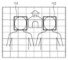
図6は、光学系の歪みが無視できる程度である場合の表示画像とフォーカス枠との例を示す図である。なお、図面において、図6のように画像中に示されるグリッドは、画像の歪みの程度を視覚的に掴みやすくするために付加されたものであり、実際には表示されない。図6では、グリッドで表される正方形に歪みがなく、光学系の歪みが無視できる程度(つまり、歪み補正の必要がない程度)であることを示している。 FIG. 6 is a diagram illustrating an example of a display image and a focus frame when the distortion of the optical system is negligible. In the drawing, the grid shown in the image as shown in FIG. 6 is added to make it easy to visually grasp the degree of distortion of the image, and is not actually displayed. FIG. 6 shows that there is no distortion in the square represented by the grid, and the distortion of the optical system is negligible (that is, the distortion correction is not necessary).
このような場合、フォーカス枠111及び112は、表示画像中の顔領域と対応した位置に表示されることはもちろん、表示画像の元となっている撮像画像中の顔領域ともよく対応している。これは、撮像画像から表示画像を生成する際に歪み補正を行っていないことから当然の結果である。
In such a case, the
フォーカス枠111及び112と撮像画像の顔領域との対応が適正であるため、合焦制御領域内の合焦制御では、被写体の顔の位置における合焦評価値が最も高くなる。図8(a)が、この状態を表しているものとする。
Since the correspondence between the
一方、図7に示すように、光学系の特性により、撮像画像に歪みが生じたとする。図7では、グリッドの変形からたる型歪みが生じていることが分かる。このように一見して判別できるような歪みを有する画像を表示することは好ましくないため、表示画像の生成時に歪み補正が行われる。そして、歪み補正された表示画像に基づいて顔検出処理が行われる。その結果、撮像画像に歪みが生じた場合も、図6と同等の表示がなされ、見かけ上は区別が付かない。しかし、見かけ上フォーカス枠111及び112が示す領域と、合焦制御領域との関係は、撮像画像に歪みがない場合と異なったものとなる。
On the other hand, as shown in FIG. 7, it is assumed that the captured image is distorted due to the characteristics of the optical system. In FIG. 7, it can be seen that a barrel distortion has occurred due to the deformation of the grid. Since it is not preferable to display an image having distortion that can be discriminated at a glance in this manner, distortion correction is performed when a display image is generated. Then, face detection processing is performed based on the display image whose distortion has been corrected. As a result, even when the captured image is distorted, the same display as that in FIG. 6 is displayed, and it is apparently indistinguishable. However, apparently the relationship between the areas indicated by the
つまり、歪み補正後の表示画像における顔領域に対応したフォーカス枠111及び112の位置は、歪みを有する撮像画像における顔領域に対応したフォーカス枠113及び114の位置から、歪みに応じた量だけずれることになる。
That is, the positions of the
この結果、フォーカス枠111及び112に対応した撮像画像中の領域を用いて合焦制御の評価値を求めると、顔とは異なる被写体に合焦するように制御してしまう場合がある。例えば、図7に示す例では、撮像画像中の、フォーカス枠111及び112に対応する領域内に、背景の家のように高コントラストの被写体が含まれる。そのため、顔領域ではなく、家に焦点が合うように制御してしまう。図8(b)は、焦点制御領域中に含まれる顔以外の画像の影響によって顔とは異なる距離の評価値が高くなった合焦評価値の例を示す。
As a result, when the evaluation value of the focus control is obtained using the area in the captured image corresponding to the
このように、従来技術では、表示用の画像から検出した顔領域の情報を、そのまま撮像画像に当てはめて焦点制御領域を決定していた。そのため、撮像画像の歪みが無視できる程度で、表示用画像が歪み補正されない場合には問題ないが、歪みが無視できず、表示用画像が歪み補正される場合には、顔領域でない部分に合焦してしまう虞があった。 As described above, in the related art, the focus control area is determined by applying the face area information detected from the display image to the captured image as it is. For this reason, there is no problem if the distortion of the captured image is negligible and the display image is not corrected for distortion.However, if the distortion cannot be ignored and the display image is corrected for distortion, it fits into a non-face area. There was a risk of getting burned.
本発明はこのような従来技術の問題点を解決するためになされたものであり、撮像画像に歪みが生じた場合であっても正しく顔領域に合焦可能な撮像装置を提供することを目的とする。 The present invention has been made to solve such problems of the prior art, and an object of the present invention is to provide an imaging apparatus capable of correctly focusing on a face area even when a captured image is distorted. And
上述の目的は、光学系により結像された被写体像を画像データに変換する撮像手段と、画像データに反映された光学系による光学歪みを補正し、補正画像データを出力する歪み補正手段と、画像データと補正画像データに対して顔検出処理を行い、検出された顔領域を示す顔領域情報を出力する顔検出手段と、顔検出手段が出力する顔領域情報のうち、画像データに対する顔領域情報に基づいて、画像データの顔領域に含まれる画像データを特定し、当該特定された画像データに基づいて光学系の合焦状態を検出する焦点検出手段と、補正画像データに、補正画像データに対する顔領域情報に基づくフォーカス枠を重畳させて表示装置に表示する表示制御手段とを有することを特徴とする本発明の撮像装置によって達成される。 The above-described objects are: an imaging unit that converts a subject image formed by an optical system into image data; a distortion correction unit that corrects optical distortion caused by the optical system reflected in the image data and outputs corrected image data; Face detection means for performing face detection processing on the image data and the corrected image data, and outputting face area information indicating the detected face area, and among the face area information output by the face detection means, the face area for the image data Based on the information, the image data included in the face area of the image data is specified, and the focus detection means for detecting the in-focus state of the optical system based on the specified image data, and the corrected image data It is achieved by an imaging apparatus of the present invention comprising display control means for displaying on a display device by superimposing a focus frame based on face area information for.
このような構成により、本発明によれば、撮像画像に歪みが生じた場合であっても正しく顔領域に合焦可能な撮像装置が実現できる。 With such a configuration, according to the present invention, it is possible to realize an imaging apparatus that can correctly focus on a face area even when a captured image is distorted.
<第1の実施形態>
以下、添付図面を参照して本発明の好適な実施形態について説明する。
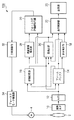
図1は、本発明の第1の実施形態に係る撮像装置の一例としてのデジタルカメラ100の機能構成例を示すブロック図である。
<First Embodiment>
Preferred embodiments of the present invention will be described below with reference to the accompanying drawings.
FIG. 1 is a block diagram illustrating a functional configuration example of a
図1において、光学系2は1枚又は複数枚のレンズで構成され、被写体像を結像する。光学系2は、自動焦点制御に用いるフォーカスレンズも備えている。被写体像の光学歪みは、被写体からの光線が光学系2を通過する過程で、光学系2を構成するレンズの収差によって生じる。
In FIG. 1, an
モータ4は光学系2のフォーカスレンズを移動させる。撮像素子10は例えば数百万画素程度の画素数を有する光電変換素子であり、CCDセンサーやCMOSセンサーなどが一般に用いられる。光学系2が結像した被写体像を撮像素子10により画素単位の電気信号(画像信号)に変換する。なお、撮像素子10には通常カラーフィルターや光学ローパスフィルタ等の周辺部品が設けられるが、本発明とは直接関係ないため説明を省略する。
The
撮像素子10から読み出されたアナログ画像信号は、A/D変換器12によりデジタル画像データに変換される。
The analog image signal read from the
フレームバッファ14は、DRAMやDRAMの読み書きを制御するメモリコントローラなどで構成される。フレームバッファ14は、A/D変換器12からの画像データや、後述する現像処理部16からの現像済み画像データを一時的に蓄えるために用いられる。
The
現像処理部16は、A/D変換器12からのデジタル画像データやフレームバッファ14で保持されたデジタル画像データに対して現像処理を行う。具体的には、例えばデジタルカメラで一般的に用いられるJPEG形式の画像データファイルを生成する前段階のYUVデータを生成する。
The
歪み補正部18は、光学系2を構成するレンズの収差によって被写体像及び撮像画像データに生じる光学歪み、例えば糸巻き型やたる型の歪みを補正し、歪みの無い被写体像を表す画像データ(補正画像データ)を出力する。本実施形態において、歪み補正部18は、フレームバッファ14に記憶された画像データに対し、読み出し方法を調整することにより画像データに反映された光学歪みを補正する。
The
顔検出部20は、現像処理部16が出力するYUV形式の画像データ又は、歪み補正部18が出力する補正画像データに対して顔検出処理を行い、被写体中に含まれる人間の顔の領域(顔領域)を検出する。顔検出部20における顔検出結果は、顔領域情報(例えば顔領域の位置情報)として表示制御部22及び測距領域指定部28へ供給される。表示制御部22は、顔検出部20からの顔領域情報に基づき、補正画像データにおける顔領域を示すフォーカス枠を決定し、フォーカス枠の表示データを生成する。フォーカス枠は、例えば顔領域に外接する方形状の枠である。そして、表示制御部22は、表示部23に対し、フレームバッファ14からの画像データもしくは歪み補正部18からの補正画像データと、フォーカス枠との合成画像データを表示させる。なお、本実施形態においては説明及び理解を容易にするため、常に補正画像データを表示するものとする。
The
なお、顔検出部20が検出する顔領域は必ずしも顔全体を含む必要はなく、顔の一部領域であっても良い。なお、一部領域である場合には、少なくとも眼の領域を含むことが好ましい。
Note that the face area detected by the
表示部23は、例えばLCDであり、デジタルカメラ100の各種設定を行うためのユーザインタフェースを表示したり、撮影した画像を再生表示したり、電子ビューファインダーとして機能したりする。なお、表示部23はテレビジョン受像機やディスプレイモニタの様な外部装置であっても良い。
The
測距領域指定部28は、顔検出部20からの顔領域情報に基づき、撮像画像データ中の、合焦制御に用いる合焦制御領域を決定する。具体的には、測距領域指定部28は、現像処理部16が出力するYUV形式の画像データに対し、顔領域情報が示す顔領域に対応する領域(例えば顔領域に外接する方形状領域)を合焦制御領域として指定する。そして、測距領域指定部28は、指定した合焦制御領域に関する情報(例えば、合焦制御領域の位置と大きさを表す情報)をフォーカス用評価値取得部30へ出力する。
The distance measurement
フォーカス用評価値取得部30は、測距領域指定部28から供給される合焦制御領域に関する情報に基づいて、現像処理部16から合焦制御領域に対応する輝度(Y)成分データを取得し、この輝度成分データから光学系の合焦状態を示すフォーカス用評価値を算出する。フォーカス用評価値は、合焦制御部32へ供給される。このフォーカス用評価値取得部30と合焦制御部32をあわせて焦点検出部と称する。
The focus evaluation
合焦制御部32は、フォーカス用評価値取得部30からの評価値を受けて、フォーカスモータ駆動部34を制御し、評価値が最大となる位置を探索する。フォーカスモータ駆動部34は、合焦制御部32からの指示によってモータ4を制御し、光学系2に含まれるフォーカスレンズを移動させる。
The
次に、本実施形態における歪み補正部18の動作についてさらに説明する。
光学レンズには収差があるため、光学レンズを介して結像される被写体像には光学歪みが発生する。撮像素子は光学系2が結像する被写体像をそのまま画像信号に変換するため、画像信号も被写体像が有する光学歪みの影響を受ける。代表的な光学歪みには、図2(a)に示すような「糸まき型歪み」や図2(b)に示すような「たる型歪み」がある。図2は、点線で示した範囲の被写体の像が、光学歪みにより実線の形状で結像されていることを示す。
Next, the operation of the
Since the optical lens has aberration, optical distortion occurs in the subject image formed through the optical lens. Since the imaging device converts the subject image formed by the
被写体像の光学歪みは、例えば、被写体像をデジタルデータ化し、歪みに応じて画素データを再配置することで補正することが可能である。
例えば、図3のように、たる型歪みが生じた画像を補正する場合を考える。図3においては、A〜D点が歪みによりa〜d点に結像した状態を示している。この場合、実線で示される歪んだ被写体像は、A/D変換器12によりデジタル画像データに変換され、フレームバッファ14に一時記憶される。
The optical distortion of the subject image can be corrected by, for example, converting the subject image into digital data and rearranging the pixel data according to the distortion.
For example, consider the case of correcting an image in which a barrel distortion occurs as shown in FIG. FIG. 3 shows a state where points A to D are imaged at points a to d due to distortion. In this case, the distorted subject image indicated by the solid line is converted into digital image data by the A /
歪み補正部18は、補正後の画像を生成する際、A点の画素としてa点の画素を、B点の画素としてb点の画素を、C点の画素としてc点の画素を、D点の画素としてd点の画素をそれぞれ読み出すことにより、歪みを補正した画像を生成することができる。なお、歪みによりA−B間の画素数と実際のa−b間の画素数とが異なる場合、補間や間引きなどにより画素数を合わせることができる。光学歪みを補正する方法については、従来からさまざまな提案がされており、また本発明においてはどのような補正方法も理論上使用可能であるため、これ以上の説明は行わない。
When generating the corrected image, the
次に、顔検出部20の動作について説明する。
本実施形態において、人物の顔領域の検出には、公知の顔検出技術を利用できる。
具体的には、非特許文献1に記載されるような、主成分分析による固有顔(eigenface)を用いた方法や、特許文献6に記載されるような、目、鼻、口等の特徴点を利用した方法を利用可能である。これらの方法は、入力画像と複数の標準パターンとのパターンマッチング結果に基づき、入力画像中に人物の顔が含まれているかどうかを判定するものである。
Next, the operation of the
In the present embodiment, a known face detection technique can be used to detect a human face area.
Specifically, as described in
本実施形態では、顔検出部20に予め人物の顔の標準パターンを保持させておく。そして、顔検出部20は、フレームバッファ14のDRAMに保存されている撮像画像データ又は、歪み補正部18が出力する補正画像データと、標準パターンとの間でパターンマッチングを行い、人物の顔が含まれるか否かを判定する。人物の顔と判定される領域(顔領域)が検出された場合、顔検出部20は個々の顔領域についての情報を表示制御部22及び測距領域指定部28へ出力する。この、顔領域についての情報は、表示制御部22及び測距領域指定部28が顔領域を特定可能な任意の情報であってよいが、例えば顔領域に外接する最小の方形を規定する座標値などであってよい。
In the present embodiment, the
次に、本実施形態のデジタルカメラ100におけるオートフォーカス動作について説明する。
一般に、被写体に人物が含まれる場合、その人物に合焦した撮影が望まれることが多いが、特に人物が撮影範囲の中央にいない場合など、背景に合焦してしまうことがある。そのため、顔検出技術を用い、被写体中の人物の顔に合焦するような合焦制御を行うことで、ユーザの意図に沿った撮影結果を提供できる可能性が高くなると考えられる。
Next, the autofocus operation in the
In general, when a subject includes a person, it is often desired to take a picture focused on the person, but the subject may be focused on the background, particularly when the person is not in the center of the shooting range. For this reason, it is considered that by using the face detection technique and performing focus control so as to focus on the face of a person in the subject, it is possible to increase the possibility of providing a photographing result according to the user's intention.
しかし、従来技術の課題として説明したように、従来は表示用画像に対して顔検出を行った結果をそのまま用いて合焦制御領域を指定していた。そのため、表示用画像が歪み補正されている場合には、表示用画像で検出される顔領域と、合焦制御に用いる撮像画像中の顔領域とにずれが生じ、期待される合焦制御結果が得られない場合があった。 However, as described as the problem of the prior art, conventionally, the focus control area is designated using the result of face detection for the display image as it is. Therefore, when the display image is corrected for distortion, a shift occurs between the face area detected in the display image and the face area in the captured image used for focus control, and an expected focus control result. May not be obtained.
このずれを解消するには、合焦制御にも歪み補正後の画像データを使用することが考えられるが、以下の点から望ましくない。1つは、歪み補正を行うと、合焦制御の評価値を求める上で重要な高周波数成分が失われ、合焦精度が低下することである。もう1つは、歪み補正処理は高負荷な処理であるため処理時間がかかり、合焦位置を決定するまでの時間が増加する要因となることである。 In order to eliminate this shift, it is conceivable to use image data after distortion correction for focusing control, but this is not desirable from the following points. One is that when distortion correction is performed, high-frequency components that are important in obtaining an evaluation value for focusing control are lost, and focusing accuracy is reduced. The other is that the distortion correction process is a high-load process and takes a long processing time, which increases the time until the in-focus position is determined.
そのため、本実施形態では、撮像画像データに対して顔検出する。これにより、撮像画像データが歪んでいる場合でも、合焦制御領域を撮像画像中の顔領域と正しく対応させることができる。また、一方で、フォーカス枠を表示するための顔検出を表示用画像データに対しても行う。 Therefore, in the present embodiment, face detection is performed on captured image data. Thereby, even when the captured image data is distorted, the focusing control area can be correctly associated with the face area in the captured image. On the other hand, face detection for displaying the focus frame is also performed on the display image data.
そして、1つの顔検出部20を用いて両方の顔検出処理を行うため、撮像画像データに対する顔検出処理と、表示用画像データに対する顔検出処理とを時分割処理する。
Since both face detection processes are performed using one
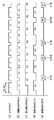
図4は、デジタルカメラ100の各部の動作タイミングを説明するためのタイミングチャートである。
図4(a)は、A/D変換器12が出力するデジタル画像データであり、表示部23を電子ビューファインダとして機能させるため、30fps(約33mSec間隔)のフレームレートを有する。図4(b)は、A/D変換器12の出力するデジタル画像データを現像処理部16で現像した結果(撮像画像データ)が出力されるタイミングを示す。撮像画像データは、現像処理に要する時間だけデジタル画像データよりも遅れて出力されている。上述のように、撮像画像データはフレームバッファ14へ一時記憶される。
FIG. 4 is a timing chart for explaining the operation timing of each part of the
FIG. 4A shows digital image data output from the A /
図4(c)は、撮像画像データをフレームバッファ14に蓄えてから、歪み補正部18による歪み補正処理が行われるタイミングを示す。図4(c)に示すように、撮像画像データは、フレームバッファ14にある程度(ここでは画像の約半分程度)蓄積された時点から歪み補正部18が読み出しを開始し、歪み補正データを生成する。
FIG. 4C shows the timing at which distortion correction processing by the
図4(d)は、顔検出部20へ供給されるデータの種別とタイミングを示す。このように、現像処理部16からの撮像画像データAn(nは1以上の整数)と、歪み補正部18からの補正画像データBnを時分割で切り替えて顔検出部20に入力するタイミングを示している。
FIG. 4D shows the type and timing of data supplied to the
本実施形態では、図4(d)に示すように、撮像画像データAnと歪み補正後の補正画像データBnを、A1、B2、A4、B5、A7・・・・と交互に入力している。ここでAnとBnの入力タイミングが時間的に等間隔にならないのは、歪み補正処理がフレームバッファ14で撮像画像データを遅延して読み出すこと、歪み補正処理の方が現像処理より時間を要することによる。このように、AnとBnとを交互に供給し、顔検出処理すると、撮像画像データに対しても補正画像データに対しても3フレーム毎の顔検出となるが、それぞれの用途に対する顔検出のスピードは10回/秒となる。このスピードは、フォーカス枠を表示させたり、合焦制御領域の決定を行うためには十分な情報量を与える。
In this embodiment, as shown in FIG. 4D, the captured image data An and the corrected image data Bn after distortion correction are alternately input as A1, B2, A4, B5, A7,. . Here, the An and Bn input timings are not equally spaced in time because the distortion correction processing reads the captured image data with a delay in the
むしろフォーカス枠の表示においては、表示の更新間隔が短いと、例えば手ぶれなどの影響で敏感に表示位置が切り替わり、フォーカス枠が見づらくなる。そのため、時間的なヒステリシスを持たせた、数回/秒の更新で十分である。同様に、顔領域を合焦制御領域とした合焦制御を行う場合も、図8に示したような評価値の山登り法により合焦距離を決定するため、合焦制御領域が頻繁に移動するより、ある程度ゆっくりした移動である方が好ましい。このような理由から、各用途において、顔領域の情報は10回/秒程度与えられれば十分である。 Rather, in the display of the focus frame, if the display update interval is short, for example, the display position is switched sensitively due to camera shake or the like, making it difficult to see the focus frame. Therefore, it is sufficient to update several times / second with temporal hysteresis. Similarly, when performing focus control using the face region as the focus control region, the focus control region moves frequently because the focus distance is determined by the hill-climbing method of evaluation values as shown in FIG. It is more preferable that the movement is slow to some extent. For this reason, it is sufficient that information on the face area is given about 10 times / second in each application.
なお、本実施形態においては、発明の理解及び説明を容易にするため、光学歪みの程度とは関係なく、合焦制御用の顔領域検出と、フォーカス枠表示用の顔領域検出とを行うものとした。このような処理を行っても、実用上問題ないことは上述したとおりであるが、歪み補正が必要ない場合はフォーカス枠表示用の顔領域検出結果を合焦制御領域の決定に用いるように構成しても良い。 In the present embodiment, in order to facilitate understanding and explanation of the invention, face area detection for focus control and face area detection for focus frame display are performed regardless of the degree of optical distortion. It was. As described above, even if such processing is performed, there is no problem in practical use. However, when distortion correction is not necessary, the focus frame display face area detection result is used to determine the focus control area. You may do it.
歪み補正の要否は、例えば光学系2の特性に応じて、予め歪み補正を行う条件(補正条件)を定めておき、補正条件に合致するか否かによって判定することができる。光学系2の特性としては、例えばレンズの焦点距離(画角)と絞りの関係であってよい。
The necessity of distortion correction can be determined based on whether or not conditions for correcting distortion (correction conditions) are determined in advance in accordance with the characteristics of the
以上説明したように、本実施形態によれば、顔領域に対して合焦制御を行うことの可能な撮像装置において、合焦制御に用いる顔領域は歪み補正前の画像データから検出する。これにより、被写体像に光学歪みがある場合であっても、正しく顔領域に対して合焦制御を行うことができ、精度良い合焦制御が実現される。 As described above, according to the present embodiment, in an imaging apparatus capable of performing focus control on a face area, the face area used for focus control is detected from image data before distortion correction. Thereby, even when the subject image has optical distortion, the focus control can be correctly performed on the face region, and the focus control with high accuracy is realized.
さらに、フォーカス枠を表示するための顔領域は、表示に用いる歪み補正後の画像データから検出することができる。この場合、被写体像に光学歪みがある場合であっても、歪みのない画像データにおける顔領域に対応したフォーカス枠を表示することができる。 Furthermore, the face area for displaying the focus frame can be detected from the image data after distortion correction used for display. In this case, even when the subject image has optical distortion, it is possible to display a focus frame corresponding to the face area in the image data without distortion.
また、歪み補正前の画像データに対する顔検出と、歪み補正後の画像データに対する顔検出処理を、1つの顔検出部で時分割的に行うので、回路規模を増大させることがない。また、歪み補正前の画像データに対する顔検出と、歪み補正後の画像データに対する顔検出を、それぞれ離散的なフレームに対して行えばよいので、従来と同様の顔検出部で十分実施可能であり、従来構成に対してごくわずかな設計の変更を行うだけでよい。 In addition, since face detection for image data before distortion correction and face detection processing for image data after distortion correction are performed in a time-sharing manner by one face detection unit, the circuit scale is not increased. In addition, since face detection for image data before distortion correction and face detection for image data after distortion correction may be performed on discrete frames, it can be sufficiently performed by a face detection unit similar to the conventional one. Only a slight design change is required with respect to the conventional configuration.
<第2の実施形態>
図5は、本発明の第2の実施形態に係る撮像装置の一例としてのデジタルカメラ110の機能構成例を示すブロック図である。
<Second Embodiment>
FIG. 5 is a block diagram illustrating a functional configuration example of a
図5において、図1と同じ構成には同じ参照数字を付してその説明を省略する。本実施形態のデジタルカメラ110は、顔検出部を2つ(第1の顔検出部24と第2の顔検出部26)を有する点である。第1及び第2の顔検出部24及び26の各々は、第1の実施形態における顔検出部20と同等の構成であって良い。
5, the same components as those in FIG. 1 are denoted by the same reference numerals, and the description thereof is omitted. The
第1の顔検出部24は補正画像データに対する顔検出処理を、第2の顔検出部26は画像データに対する顔検出処理をそれぞれ独立して行う。従って、第1の実施形態では時分割的に行っていた顔検出処理を並列して実行することが可能となり、顔領域情報が、合焦制御用、フォーカス枠表示用ともに撮像素子10の出力フレームレート(30fps)と同じスピード30回/秒で取得可能である。
The first
このように、第1の実施形態と同様、被写体像に光学歪みがある場合であっても、正しく顔領域に対して合焦制御を行うことができる。また、被写体像に光学歪みがある場合であっても、歪みのない画像データにおける顔領域に対応したフォーカス枠を表示することができる。さらに本実施形態では、回路規模は増大するものの、よりきめ細かな処理が可能となり、動きの大きな人物の撮影時などにおいて、追従性に優れた合焦制御を行うことが可能となる。 As described above, as in the first embodiment, even when the subject image has optical distortion, the focus control can be correctly performed on the face area. Further, even when the subject image has optical distortion, it is possible to display a focus frame corresponding to a face area in image data without distortion. Furthermore, in this embodiment, although the circuit scale increases, finer processing is possible, and it is possible to perform focus control with excellent followability when shooting a person with large movement.
Claims (3)
前記画像データに反映された前記光学系による光学歪みを補正し、補正画像データを出力する歪み補正手段と、
前記画像データと前記補正画像データに対して顔検出処理を行い、検出された顔領域を示す顔領域情報を出力する顔検出手段と、
前記顔検出手段が出力する前記顔領域情報のうち、前記画像データに対する顔領域情報に基づいて、前記画像データの前記顔領域に含まれる画像データを特定し、当該特定された画像データに基づいて前記光学系の合焦状態を検出する焦点検出手段と、
前記補正画像データに、前記補正画像データに対する顔領域情報に基づくフォーカス枠を重畳させて表示装置に表示する表示制御手段とを有することを特徴とする撮像装置。 Imaging means for converting a subject image formed by the optical system into image data;
Distortion correcting means for correcting optical distortion caused by the optical system reflected in the image data and outputting corrected image data;
Face detection means for performing face detection processing on the image data and the corrected image data, and outputting face area information indicating the detected face area;
Among the face area information output by the face detection means, the image data included in the face area of the image data is specified based on the face area information for the image data, and based on the specified image data Focus detection means for detecting the in-focus state of the optical system ;
An image pickup apparatus comprising: a display control unit configured to superimpose a focus frame based on face area information on the corrected image data and display the correction image data on a display device.
Priority Applications (1)
| Application Number | Priority Date | Filing Date | Title |
|---|---|---|---|
| JP2006299384A JP4953770B2 (en) | 2006-11-02 | 2006-11-02 | Imaging device |
Applications Claiming Priority (1)
| Application Number | Priority Date | Filing Date | Title |
|---|---|---|---|
| JP2006299384A JP4953770B2 (en) | 2006-11-02 | 2006-11-02 | Imaging device |
Publications (3)
| Publication Number | Publication Date |
|---|---|
| JP2008116663A JP2008116663A (en) | 2008-05-22 |
| JP2008116663A5 JP2008116663A5 (en) | 2009-12-17 |
| JP4953770B2 true JP4953770B2 (en) | 2012-06-13 |
Family
ID=39502649
Family Applications (1)
| Application Number | Title | Priority Date | Filing Date |
|---|---|---|---|
| JP2006299384A Expired - Fee Related JP4953770B2 (en) | 2006-11-02 | 2006-11-02 | Imaging device |
Country Status (1)
| Country | Link |
|---|---|
| JP (1) | JP4953770B2 (en) |
Families Citing this family (6)
| Publication number | Priority date | Publication date | Assignee | Title |
|---|---|---|---|---|
| JP5349877B2 (en) * | 2008-09-11 | 2013-11-20 | キヤノン株式会社 | IMAGING DEVICE AND IMAGING DEVICE CONTROL METHOD |
| JP5457008B2 (en) * | 2008-10-16 | 2014-04-02 | 富士フイルム株式会社 | Autofocus system with AF frame auto-tracking function |
| JP5049300B2 (en) * | 2009-01-20 | 2012-10-17 | クラリオン株式会社 | Obstacle detection display |
| JP5999746B2 (en) * | 2010-03-31 | 2016-09-28 | カシオ計算機株式会社 | Imaging apparatus, AF evaluation value calculation method, and program |
| JP6196772B2 (en) * | 2012-12-21 | 2017-09-13 | キヤノン株式会社 | FOCUS DETECTION DEVICE, FOCUS DETECTION METHOD AND PROGRAM, AND IMAGING DEVICE |
| JP6016622B2 (en) * | 2012-12-26 | 2016-10-26 | キヤノン株式会社 | Imaging apparatus, control method therefor, and program |
Family Cites Families (3)
| Publication number | Priority date | Publication date | Assignee | Title |
|---|---|---|---|---|
| JP3260929B2 (en) * | 1993-10-15 | 2002-02-25 | オリンパス光学工業株式会社 | Video processing device |
| JP4154400B2 (en) * | 2004-04-01 | 2008-09-24 | キヤノン株式会社 | Imaging apparatus, control method thereof, and program |
| JP2006018246A (en) * | 2004-06-03 | 2006-01-19 | Canon Inc | Imaging apparatus and imaging method |
-
2006
- 2006-11-02 JP JP2006299384A patent/JP4953770B2/en not_active Expired - Fee Related
Also Published As
| Publication number | Publication date |
|---|---|
| JP2008116663A (en) | 2008-05-22 |
Similar Documents
| Publication | Publication Date | Title |
|---|---|---|
| JP4732303B2 (en) | Imaging device | |
| JP4154400B2 (en) | Imaging apparatus, control method thereof, and program | |
| JP4784678B2 (en) | Imaging apparatus, imaging method, and program | |
| CN101076997B (en) | Image processing and image processing method used therein | |
| JP5029137B2 (en) | Imaging apparatus and program | |
| EP1845709A2 (en) | Image capturing apparatus, control method therefor, image processing apparatus, image processing method, and program | |
| JP6222514B2 (en) | Image processing apparatus, imaging apparatus, and computer program | |
| JP5950678B2 (en) | Imaging apparatus, control method, and program | |
| JP2007129587A (en) | Imaging apparatus, interchangeable lens apparatus, imaging control method, data processing method for distortion aberration correction and computer program | |
| JP2008109336A (en) | Image processor and imaging apparatus | |
| JP2013165485A (en) | Image processing apparatus, image capturing apparatus, and computer program | |
| JP4953770B2 (en) | Imaging device | |
| JP4125331B2 (en) | Imaging apparatus and control method thereof | |
| JP2005215373A (en) | Imaging apparatus | |
| JP2009213114A (en) | Imaging device and program | |
| JP2013135410A (en) | Imaging device and evaluation value generation device | |
| JP2011114486A (en) | Imaging device | |
| JP6024135B2 (en) | Subject tracking display control device, subject tracking display control method and program | |
| JP5393877B2 (en) | Imaging device and integrated circuit | |
| JP6862225B2 (en) | Imaging device, control method of imaging device, and program | |
| JP2017063340A (en) | Image blur correction device, imaging device, and control method | |
| JP2009027437A (en) | Image processor, image processing method and imaging device | |
| JP2020184698A (en) | Imaging apparatus and control method of the same | |
| JP7271316B2 (en) | Imaging device and its control method | |
| US11743601B2 (en) | Image processing device, image processing method, and storage medium |
Legal Events
| Date | Code | Title | Description |
|---|---|---|---|
| A521 | Request for written amendment filed |
Free format text: JAPANESE INTERMEDIATE CODE: A523 Effective date: 20091028 |
|
| A621 | Written request for application examination |
Free format text: JAPANESE INTERMEDIATE CODE: A621 Effective date: 20091028 |
|
| A131 | Notification of reasons for refusal |
Free format text: JAPANESE INTERMEDIATE CODE: A131 Effective date: 20111007 |
|
| TRDD | Decision of grant or rejection written | ||
| A01 | Written decision to grant a patent or to grant a registration (utility model) |
Free format text: JAPANESE INTERMEDIATE CODE: A01 Effective date: 20120309 |
|
| A01 | Written decision to grant a patent or to grant a registration (utility model) |
Free format text: JAPANESE INTERMEDIATE CODE: A01 |
|
| A61 | First payment of annual fees (during grant procedure) |
Free format text: JAPANESE INTERMEDIATE CODE: A61 Effective date: 20120313 |
|
| R151 | Written notification of patent or utility model registration |
Ref document number: 4953770 Country of ref document: JP Free format text: JAPANESE INTERMEDIATE CODE: R151 |
|
| FPAY | Renewal fee payment (event date is renewal date of database) |
Free format text: PAYMENT UNTIL: 20150323 Year of fee payment: 3 |
|
| LAPS | Cancellation because of no payment of annual fees |