JP5950678B2 - Imaging apparatus, control method, and program - Google Patents
Imaging apparatus, control method, and program Download PDFInfo
- Publication number
- JP5950678B2 JP5950678B2 JP2012103830A JP2012103830A JP5950678B2 JP 5950678 B2 JP5950678 B2 JP 5950678B2 JP 2012103830 A JP2012103830 A JP 2012103830A JP 2012103830 A JP2012103830 A JP 2012103830A JP 5950678 B2 JP5950678 B2 JP 5950678B2
- Authority
- JP
- Japan
- Prior art keywords
- image
- images
- imaging
- angle
- view
- Prior art date
- Legal status (The legal status is an assumption and is not a legal conclusion. Google has not performed a legal analysis and makes no representation as to the accuracy of the status listed.)
- Active
Links
Images


Classifications
-
- H—ELECTRICITY
- H04—ELECTRIC COMMUNICATION TECHNIQUE
- H04N—PICTORIAL COMMUNICATION, e.g. TELEVISION
- H04N23/00—Cameras or camera modules comprising electronic image sensors; Control thereof
- H04N23/60—Control of cameras or camera modules
- H04N23/69—Control of means for changing angle of the field of view, e.g. optical zoom objectives or electronic zooming
-
- H—ELECTRICITY
- H04—ELECTRIC COMMUNICATION TECHNIQUE
- H04N—PICTORIAL COMMUNICATION, e.g. TELEVISION
- H04N23/00—Cameras or camera modules comprising electronic image sensors; Control thereof
- H04N23/70—Circuitry for compensating brightness variation in the scene
- H04N23/741—Circuitry for compensating brightness variation in the scene by increasing the dynamic range of the image compared to the dynamic range of the electronic image sensors
-
- H—ELECTRICITY
- H04—ELECTRIC COMMUNICATION TECHNIQUE
- H04N—PICTORIAL COMMUNICATION, e.g. TELEVISION
- H04N25/00—Circuitry of solid-state image sensors [SSIS]; Control thereof
- H04N25/50—Control of the SSIS exposure
- H04N25/57—Control of the dynamic range
- H04N25/58—Control of the dynamic range involving two or more exposures
- H04N25/587—Control of the dynamic range involving two or more exposures acquired sequentially, e.g. using the combination of odd and even image fields
-
- H—ELECTRICITY
- H04—ELECTRIC COMMUNICATION TECHNIQUE
- H04N—PICTORIAL COMMUNICATION, e.g. TELEVISION
- H04N25/00—Circuitry of solid-state image sensors [SSIS]; Control thereof
- H04N25/60—Noise processing, e.g. detecting, correcting, reducing or removing noise
- H04N25/61—Noise processing, e.g. detecting, correcting, reducing or removing noise the noise originating only from the lens unit, e.g. flare, shading, vignetting or "cos4"
Landscapes
- Engineering & Computer Science (AREA)
- Multimedia (AREA)
- Signal Processing (AREA)
- Studio Devices (AREA)
- Television Signal Processing For Recording (AREA)
Description
本発明は、撮像装置、制御方法、及びプログラムに関し、特に複数の画像を合成した合成画像をフレームとした動画像の生成技術に関する。 The present invention relates to an imaging apparatus, a control method, and a program, and more particularly, to a moving image generation technique using a composite image obtained by combining a plurality of images as a frame.
デジタルカメラ等の撮像装置に使用される、例えばCCDやCMOSセンサ等の撮像素子の階調範囲(ダイナミックレンジ)は、一般に銀塩フィルムが有する階調範囲よりも狭い。階調範囲が狭い場合、撮影環境によっては撮影により得られる撮影画像において、高輝度の被写体が白飛びしたり、低輝度の被写体が黒つぶれしたりすることがある。 For example, the gradation range (dynamic range) of an image sensor such as a CCD or CMOS sensor used in an imaging apparatus such as a digital camera is generally narrower than the gradation range of a silver salt film. When the gradation range is narrow, depending on the shooting environment, in a captured image obtained by shooting, a high-luminance subject may be blown out or a low-luminance subject may be blackened.
近年では、このような撮像素子であっても、露出量を異ならせて被写体を撮影した複数の画像を合成することで、階調範囲を拡張した、所謂HDR(High Dynamic Range)画像を生成する撮像装置がある。HDR画像の生成には、例えば被写体についての適正露出として設定された露出量で撮影した中間露出画像、露出オーバーとなる露出量で撮影した高露出画像、及び露出アンダーとなる露出量で撮影した低露出画像が用いられる(特許文献1)。 In recent years, even with such an image sensor, a so-called HDR (High Dynamic Range) image with an expanded gradation range is generated by combining a plurality of images obtained by photographing a subject with different exposure amounts. There is an imaging device. For the generation of HDR images, for example, an intermediate exposure image captured with an exposure amount set as an appropriate exposure for a subject, a high exposure image captured with an overexposure amount, and a low exposure image captured with an underexposure amount. An exposure image is used (Patent Document 1).
またHDR画像の生成のような、同一の被写体を撮影した複数の画像を合成する画像補正技術は、例えば手振れ補正技術等にも用いられる。なお、このような画像補正技術においては、被合成画像は全て同一の画角で被写体を撮影されている必要がある。 Further, an image correction technique for synthesizing a plurality of images taken of the same subject, such as generation of an HDR image, is also used for a camera shake correction technique, for example. In such an image correction technique, it is necessary that all the synthesized images have been photographed with the same angle of view.
一方、静止画撮影に限らず、動画撮影においても上述した画像補正技術は適用可能である。即ち、撮影された動画像の複数のフレームを合成に用いることで得られた画像を最終的な動画像のフレームとすることで、例えば階調範囲を拡張した動画像(HDR動画像)を生成することも可能である。 On the other hand, the above-described image correction technique can be applied not only to still image shooting but also to moving image shooting. That is, an image obtained by using a plurality of frames of a captured moving image for synthesis is used as a final moving image frame, for example, to generate a moving image (HDR moving image) with an expanded gradation range, for example. It is also possible to do.
しかしながら、動画像の撮影においては、所定のルールにより合成に用いるフレームが選択された場合に、選択されたフレーム間で画角が異なる場合がある。即ち、動画像の撮影においては撮影者により行われたズーム操作によって、含まれるフレームの画角が異なっている可能性がある。このため、上述のような画像補正技術を用いて各フレームを生成した動画像では、フレーム内で画質の異なる箇所がある、あるいはフレーム間で画質が異なる可能性があった。 However, in shooting a moving image, when a frame used for composition is selected according to a predetermined rule, the angle of view may be different between the selected frames. In other words, when shooting a moving image, there is a possibility that the angle of view of the included frame differs depending on the zoom operation performed by the photographer. For this reason, in a moving image in which each frame is generated using the image correction technique as described above, there is a possibility that there are portions where the image quality is different within the frame, or the image quality is different between frames.
本発明は、上述の問題点に鑑みてなされたものであり、動画像の複数のフレームを合成したフレームを用いて、好適な画質の動画像を生成する撮像装置、制御方法、及びプログラムを提供すること目的とする。 The present invention has been made in view of the above-described problems, and provides an imaging apparatus, a control method, and a program that generate a moving image with a suitable image quality using a frame obtained by combining a plurality of frames of a moving image. The purpose is to do.
前述の目的を達成するために、本発明の画像処理装置は、以下の構成を備える。
被写体を異なる露出量で順次撮像して得られた画像を取得する取得手段と、取得手段により取得された複数の画像を合成し、得られた合成画像をフレームとする動画像を生成する生成手段と、を有し、生成手段は、複数の画像について撮像時の画角が異なる場合に、複数の画像のうちの基準とする1つの基準画像と撮像時の画角が異なる画像の画角を調整することで、複数の画像を該基準画像と対応する画角を有する画像に変更して合成することを特徴とする。
In order to achieve the above object, an image processing apparatus of the present invention comprises the following arrangement.
An acquisition unit acquire an image obtained by sequentially imaging an object at different exposure amount, and combining the images acquired by the acquisition means, generating means for generating a moving image to the frame and the resulting composite image And when the angle of view at the time of imaging is different for a plurality of images, the generating means calculates the angle of view of an image having a different angle of view at the time of imaging from one reference image of the plurality of images as a reference. By adjusting, the plurality of images are changed to images having an angle of view corresponding to the reference image and synthesized.
このような構成により本発明によれば、動画像の複数のフレームを合成したフレームを用いて、好適な画質の動画像を生成することが可能となる。 With such a configuration, according to the present invention, it is possible to generate a moving image with suitable image quality using a frame obtained by combining a plurality of frames of a moving image.
[実施形態]
以下、本発明の例示的な実施形態について、図面を参照して詳細に説明する。なお、以下に説明する一実施形態は、撮像装置の一例としての、HDR動画を撮影可能なデジタルカメラに、本発明を適用した例を説明する。しかし、本発明は、撮像により順次取得された複数の画像を合成することで動画像の1つのフレームを生成可能な任意の機器に適用可能である。
[Embodiment]
Hereinafter, exemplary embodiments of the present invention will be described in detail with reference to the drawings. In the following embodiment, an example in which the present invention is applied to a digital camera capable of shooting an HDR moving image as an example of an imaging apparatus will be described. However, the present invention can be applied to any device that can generate one frame of a moving image by combining a plurality of images sequentially acquired by imaging.
《デジタルカメラ100の構成》
図1(a)は、本発明の実施形態に係るデジタルカメラ100の機能構成を示すブロック図である。
<< Configuration of
FIG. 1A is a block diagram showing a functional configuration of the
システム制御部114は、例えばCPUであり、デジタルカメラ100が備える各ブロックの動作を制御する。具体的にはシステム制御部114は、不図示のROMに格納されている、後述のHDR動画撮影処理の動作プログラムを読み出し、不図示のRAMに展開して実行することにより各ブロックの動作を制御する。
The
本実施形態のデジタルカメラ100は、ズームレンズ101、シフトレンズ103、及びフォーカスレンズ104で構成される、所謂3郡構成の撮像光学系を有する。1群レンズであるズームレンズ101は、光軸方向に位置を変更することで、後述する撮像素子105に結像される光学像における被写体像の倍率を変更する。ズームレンズ101は、ズーム駆動制御部109により駆動される。2群レンズであるシフトレンズ103は、光軸に略直交する平面内において位置を変更して撮像素子105に結像される光学像の位置を移動することで、振れ補正光学系を実現する。シフトレンズ103は、シフトレンズ駆動制御部111により駆動される。3群レンズであるフォーカスレンズ104は、光軸方向に位置を変更することで、撮像素子105に結像される光学像についての焦点調整を行う。フォーカスレンズ104は、焦点調節動作中にフォーカス駆動制御部112により駆動される。
The
また撮像光学系の光軸上において、ズームレンズ101とシフトレンズ103との間にはメカシャッタ・絞りユニット102が設けられている。メカシャッタ・絞りユニット102は、設定された露出設定のシャッタ速度及び絞り値に応じてシャッタ・絞り駆動制御部110により駆動される。メカシャッタ・絞りユニット102の駆動により、撮像素子105は異なる露出量で得られた画像を出力することができる。
A mechanical shutter /
撮像素子105は、例えばCCDやCMOSセンサ等の蓄積型の光電変換素子である。撮像素子105は、撮像光学系を介して受光面に結像された光学像を光電変換し、アナログ画像信号を撮像信号処理部106に出力する。本実施形態では撮像素子105は、動画撮影時には60fpsで撮像して得られた画像を順次出力する。また撮像素子105及び撮像光学系は、後述するように撮像する画像の露出設定を交互に切り替え、露出量の高い高露出画像(High画像)と露出量の低い低露出画像(Low画像)とを交互に出力する。
The imaging element 105 is a storage type photoelectric conversion element such as a CCD or a CMOS sensor. The imaging element 105 photoelectrically converts an optical image formed on the light receiving surface via the imaging optical system, and outputs an analog image signal to the imaging
撮像信号処理部106は、撮像素子105により出力されたアナログ画像信号に対してA/D変換処理を適用して映像信号に変換し、得られた映像信号を画像データとしてフレームメモリ113に出力し、格納させる。フレームメモリ113は、撮像信号処理部106により出力された画像データを格納する格納領域である。
The imaging
映像信号処理部107は、撮像信号処理部106に格納された複数の画像データから、階調範囲を拡張したHDR動画のフレームである合成画像を生成する。本実施形態では映像信号処理部107は、上述したHigh画像とLow画像の2種類の画像データを使用して、HDR動画における1フレームの合成画像を生成するものとして説明するが、被合成画像の数等はこれに限られるものではないことは容易に想像されよう。
The video
表示部108は、例えばLCD等のデジタルカメラ100が備える表示装置である。表示部108は、撮像素子105から出力された画像信号が表示されることによって、電子ビューファインダとして機能する。また後述する記憶部118に記憶されている静止画像や動画像等の再生指示がなされた場合には、表示部108には再生指示がなされた画像あるいは動画像が表示される。
The
ズームスイッチ115及びシャッタレリーズスイッチ117は、デジタルカメラ100が備えるユーザインタフェースである。ズームスイッチ115及びシャッタレリーズスイッチ117は、それぞれズーム指示あるいは撮影指示用に設けられた操作部材である。ユーザによりズームスイッチ115あるいはシャッタレリーズスイッチ117に対して操作がなされた場合、システム制御部114は該操作部材から出力された制御信号により、該操作を検出する。
The
外部入出力端子部116は、例えばUSB等の外部接続インタフェースであり、デジタルカメラ100と他の機器とを接続する際に利用される。また記憶部118は、例えばデジタルカメラ100が有する内蔵メモリや、HDDやメモリカード等のデジタルカメラ100に着脱可能に接続される記録装置である。記憶部118には、撮影指示を受けて取得された静止画像や動画像が格納される。また電源部119は、デジタルカメラ100が有する電源供給部であり、例えばバッテリや外部の商用電源がアダプタ等を介して接続され、デジタルカメラ100が有する各ブロックに対してシステム制御部114の制御のもと、電源供給がなされる。
The external input /
〈ズーム駆動制御部109の内部構成〉
ここで、ズーム駆動制御部109の内部構成について、図1(b)を用いてさらに詳細を説明する。
<Internal Configuration of Zoom
Here, the internal configuration of the zoom
ユーザによるズームスイッチ115への操作がなされたことを検出すると、システム制御部114はズーム駆動制御部109に対して、ズームレンズ101の駆動指示に係る制御信号を送信する。このようにしてズーム駆動制御部109に入力された制御信号はズーム制御部127により受信される。ズーム制御部127は、制御信号に応じて、ズームモータ駆動回路121を制御し、ズームモータ120を駆動させることでズームレンズ101の位置を変更する。ズームモータ120は例えばDC(直流)モータ等であってよい。
When it is detected that the user has operated the
なお、ズームモータ120により移動されたズームレンズ101の駆動位置の情報は、リセット位置検出部123及びエンコーダ124により検出される。リセット位置検出部123は、ズームレンズ101がリセット位置に存在するか否かを検出するセンサである。ズーム制御部127は、リセット位置検出部123からズームレンズ101がリセット位置、即ち駆動制御における基準位置に存在することを示す信号を受信することで、ズームレンズ101の位置を精度よく検出することができる。
Information on the driving position of the
エンコーダ124は、ズームレンズ101の移動に合わせて回転し、所定角度の回転がなされた際にパルス信号を出力する。ズーム位置検出部125は、エンコーダ124により出力されたパルス信号に基づいてズーム位置、即ちズームレンズ101の位置の情報を取得する。またズーム速度検出部126は、エンコーダ124により出力されたパルス信号に基づいてズーム速度、即ちズームレンズ101の動作速度の情報を取得する。ズーム位置検出部125及びズーム速度検出部126により得られたズーム位置及びズーム速度の情報は、ズーム制御部127に出力された後、ズーム制御部127によりシステム制御部114に出力される。
The
なお、本実施形態ではハードウェアとしてデジタルカメラ100が備える各ブロックにおいて処理が実現されるものとして説明するが、本発明の実施はこれに限らず、各ブロックの処理は該各ブロックと同様の処理を行うプログラムで実現されてもよい。
In the present embodiment, description will be made assuming that processing is realized in each block included in the
《HDR動画生成の概要》
ここで、後述する本実施形態のHDR動画撮影処理における、HDR動画の1フレームであるHDR画像の生成に係る処理の概要を、図を用いて説明する。
<Overview of HDR video generation>
Here, an outline of processing related to generation of an HDR image that is one frame of an HDR moving image in HDR moving image shooting processing of the present embodiment to be described later will be described with reference to the drawings.
図2(a)は、例えばデジタルカメラ100がHDR動画撮影モードに設定されている際に、HDR動画のフレームを生成するために合成される画像データ(Low画像及びHigh画像)を示した図である。図示されるように、HDR動画生成に係る動画撮影が開始すると、垂直同期信号に応じて撮像素子105から60fps(1/60sec間隔)で、High画像及びLow画像が交互にフレームメモリ113に格納される。具体的にはシステム制御部114は、被写体輝度分布について適正露出Ev(0)を決定した後、1段明るくした露出設定Bv(H)をHigh画像の露出設定として、撮像素子105及びシャッタ・絞り駆動制御部110に露出制御を行わせる。またシステム制御部114は、適正露出から1段暗くした露出設定Bv(L)をLow画像の露出設定として、撮像素子105及びシャッタ・絞り駆動制御部110に露出制御を行わせる。このようにシステム制御部114は、60fpsで交互に露出設定を変更することで、High画像とLow画像とを順次取得することができる。
FIG. 2A is a diagram showing image data (Low image and High image) combined to generate a frame of an HDR movie when the
図2(a)の例では、動画撮影中にズーム操作がなされていない状況を示している。この場合、画角の変更がなされていないため、システム制御部114は、連続するHigh画像とLow画像とを位置合わせのみ行なわせて、映像信号処理部107に合成させることで、記録されるHDR動画のフレームに係る合成画像を取得する。
In the example of FIG. 2 (a), a zoom operation is not performed during moving image shooting. In this case, since the angle of view has not been changed, the
一方、図2(b)のように、動画撮影中にズーム操作がなされた状況を考える。図2(b)の例では、動画撮影中に、広角(WIDE)側から望遠(TELE)側に毎フレームn倍に単調増加するズーム指示がなされた場合を示している。このとき、連続して出力されるHigh画像とLow画像とは撮像時の画角が異なっており、映像信号処理部107は2つの画像を、図2(a)の例のように単純に合成することはできない。
On the other hand, as shown in FIG. 2B, consider a situation where a zoom operation is performed during moving image shooting. The example of FIG. 2B shows a case where a zoom instruction that monotonously increases n times every frame from the wide-angle (WIDE) side to the telephoto (TELE) side is shown during moving image shooting. At this time, the angle of view at the time of imaging differs between the High image and the Low image that are continuously output, and the video
このため、本実施形態のデジタルカメラ100では、動画撮影中にズーム操作がなされた複数の画像、即ち撮像時の画角の異なる複数の画像から合成画像を生成する際に、少なくともいずれかの画像に対して調整処理を行って、同一の画角の画像で合成を行う。なお、本実施形態では、High画像とLow画像の2種類の画像のみが合成に用いられるものとして説明するが、本発明の実施はこれに限られるものではない。即ち、被合成画像は3以上であってもよく、該被合成画像の撮像時の画角が異なる場合、いずれか1つの基準合成画像と画角が異なる被合成画像に対して調整処理が行なわれ、全ての被合成画像は同一の画角及び画素数を有する画像に変更されて合成に用いられる。
Therefore, in the
画角の調整処理は、例えば図3(a)に示されるように、画角の広いHigh画像から画角の狭いLow画像に対応する領域(High画像の1/nの画素数を有する領域)を抽出し、抽出した画像をn倍に拡大することにより行われればよい。即ち、High画像とLow画像との画角比に応じてHigh画像の画角調整を行う。このようにすることで、画角の異なるHigh画像とLow画像とを、同一の画角及び画素数を有する画像に変更することができる。 For example, as shown in FIG. 3A, the angle of view adjustment processing is performed from a high-angle image having a wide angle of view to a low-angle image having a small angle of view (an area having 1 / n the number of pixels of the high image). Is extracted, and the extracted image is enlarged n times. That is, the angle of view of the high image is adjusted according to the angle of view ratio between the high image and the low image. By doing in this way, it is possible to change a High image and a Low image having different angles of view to images having the same angle of view and the number of pixels.
なお、本実施形態では図3(a)のように画角の広い被合成画像から画像の抽出及び拡大処理を行うものとして説明するが、図3(b)のように、全ての被合成画像について同様の処理を行なってもよい。例えば、Low画像から1/nの画素数を有する領域を抽出してn倍して合成する場合、High画像からは抽出した領域に対応する1/n2の画素数を有する領域を抽出してn2倍して合成してもよい。しかしながら、このように全ての被合成画像について画角調整を行った場合は、撮影している動画とズーム速度や画角の見えが異なるため、本発明は少なくとも1つの被合成画像については画角調整を行わないことが好ましい。 In the present embodiment, description will be made assuming that image extraction and enlargement processing is performed from a combined image having a wide angle of view as shown in FIG. 3A. However, as shown in FIG. A similar process may be performed for. For example, when an area having a 1 / n pixel number is extracted from a Low image and synthesized by multiplying by n, an area having a 1 / n 2 pixel number corresponding to the extracted area is extracted from the High image. n 2 times to may be synthesized. However, when the angle of view is adjusted for all the combined images in this way, since the zoom speed and the angle of view are different from those of the moving image being shot, the present invention does not have the angle of view for at least one combined image. Preferably no adjustment is made.
また図2(b)では広角側から望遠側へのズーム操作がなされている例について説明したが、望遠側から広角側へのズーム操作がなされている場合、システム制御部114は次のように被合成画像の組み合わせを選択するものとする。システム制御部114は、被合成画像のうちの画角調整を行う画像、即ち広角側の被合成画像がHigh画像となるように、被合成画像の組み合わせを異ならせる。つまり、システム制御部114は広角側→望遠側のズーム操作時は、画角が広いHigh画像と、その後に得られた画角の狭いLow画像とを被合成画像として選択する。一方、システム制御部114は望遠側→広角側のズーム操作時は、画角の狭いLow画像と、その後に得られた画角の広いHigh画像とを被合成画像として選択する。これは、High画像の方が露出量が高いことに起因する。
2B illustrates the example in which the zoom operation is performed from the wide angle side to the telephoto side. However, when the zoom operation is performed from the telephoto side to the wide angle side, the
一般的に、適正露出よりも露出量を高めに設定して撮影された画像のように、白飛びや明るすぎる領域が含まれる画像は、階調範囲に含まれる被写体の情報量が少なく、画像の閲覧者に好ましくない印象を与えうる。このため、本実施形態では画角調整により情報量を低減させる画像については、もともと階調範囲に含まれる被写体の情報量が少ないHigh画像が選択されるように、システム制御部114はズーム操作に応じて被合成画像の組み合わせを異ならせる。
In general, an image that includes overexposed or too bright areas, such as an image that was shot with a higher exposure than the appropriate exposure, has a small amount of subject information in the gradation range. May give an unfavorable impression to viewers. For this reason, in this embodiment, the
なお、本実施形態ではHigh画像がLow画像よりも階調範囲に含まれる被写体の情報量が少ないものとして説明するが、被合成画像の組み合わせの決定方法はこれに限られなくてもよい。例えば、システム制御部114は、被合成画像の選択時に出力されている画像データを参照し、白飛びや黒つぶれしない階調範囲に含まれる画素数が多い画像が、画角調整を行わない被合成画像となるように、組み合わせを決定してもよい。
In the present embodiment, the description will be made on the assumption that the information amount of the subject whose High image is included in the gradation range is smaller than that of the Low image, but the method for determining the combination of the combined images is not limited thereto. For example, the
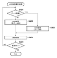
《HDR動画撮影処理》
次に、本実施形態のデジタルカメラ100のHDR動画撮影処理について、図4のフローチャートを用いて具体的な処理を説明する。該フローチャートに対応する処理は、システム制御部114が、例えば不図示のROMに記憶されている対応する処理プログラムを読み出し、RAMに展開して実行することにより実現することができる。なお、本HDR動画撮影処理は、例えばデジタルカメラ100がHDR動画撮影モードに設定されている状態で、撮影開始指示に対応する制御信号をシステム制御部114が受信した際に開始されるものとして説明する。
<< HDR movie shooting process >>
Next, specific processing of HDR moving image shooting processing of the
S401で、システム制御部114は、ズーム操作がなされているか否かを判断する。具体的にはシステム制御部114は、ズームスイッチ115に対してズーム指示がなされたことを示す制御信号をズームスイッチ115から受信したか否かを判断する。システム制御部114は、ズーム操作がなされていると判断した場合は処理をS403に移し、なされていないと判断した場合は処理をS402に移す。
In step S401, the
S402で、システム制御部114は、HDR動画のフレーム画像を生成するHDR処理(非ズーム時)を実行する。
In step S <b> 402, the
〈HDR処理(非ズーム時)〉
ここで、S402で実行されるHDR処理(非ズーム時)について、図5(a)のフローチャートを用いて詳述する。
<HDR processing (when not zoomed)>
Here, the HDR processing (at the time of non-zoom) executed in S402 will be described in detail with reference to the flowchart of FIG.
S501で、システム制御部114は、被写体の適正露出を取得し、High画像用の露出設定Ev(H)及びLow画像用の露出設定Ev(L)を決定する。
In step S501, the
S502で、システム制御部114は、High画像用の露出設定に基づいてメカシャッタ・絞りユニット102及び撮像素子105を駆動させてHigh画像を撮像させ、得られたHigh画像をフレームメモリ113に格納する。
In step S <b> 502, the
S503で、システム制御部114は、Low画像用の露出設定に基づいてメカシャッタ・絞りユニット102及び撮像素子105を駆動させてLow画像を撮像させ、得られたLow画像をフレームメモリ113に格納する。
In step S <b> 503, the
S504で、システム制御部114は、フレームメモリ113に格納されたHigh画像及びLow画像を合成させ、HDR動画の1フレームの画像を生成させる。またシステム制御部114は、生成させたフレーム画像をフレームメモリ113に格納する。
In step S504, the
このようにすることで、フレームメモリ113には、生成するHDR動画の1フレームに係る画像が格納される。
In this way, the
一方、S401においてズーム操作がなされていると判断した場合、システム制御部114はS403で、HDR動画のフレーム画像を生成するHDR処理(ズーム時)を実行する。
On the other hand, if it is determined in S401 that the zoom operation is being performed, the
〈HDR処理(ズーム時)〉
ここで、S403で実行されるHDR処理(ズーム時)について、図5(b)のフローチャートを用いて詳述する。なお、本HDR処理(ズーム時)において、上述した非ズーム時のHDR処理と同様の処理を行うステップについては、同一の参照符号を付して説明を省略し、以下ではズーム時のHDR処理に特徴的な処理を行うステップについてのみ説明する。
<HDR processing (when zooming)>
Here, the HDR process (during zooming) executed in S403 will be described in detail with reference to the flowchart of FIG. In this HDR process (during zooming), the steps for performing the same process as the above-described HDR process during non-zoom are denoted by the same reference numerals and description thereof is omitted. Hereinafter, the HDR process during zooming will be described. Only steps for performing characteristic processing will be described.
S501においてHigh画像及びLow画像の露出設定を決定した後、システム制御部114はS511で、ズーム操作の方向が広角側→望遠側か、望遠側→広角側のいずれであるかを判断する。具体的にはシステム制御部114は、例えばズームスイッチ115から受信した制御信号が、どちらの操作に対応した信号であるかを判断することにより、ズーム操作の方向を判断する。システム制御部114は、ズーム操作の方向が広角側→望遠側であると判断した場合は処理をS502に移し、望遠側→広角側であると判断した場合は処理をS514に移す。
After determining the exposure settings for the high image and the low image in S501, the
S502においてHigh画像がフレームメモリ113に格納された後、システム制御部114はS512で、High画像の撮像時のズーム位置及びズーム速度を含むズーム情報を、ズーム駆動制御部109から取得し、処理をS503に移す。
After the high image is stored in the
またS503においてLow画像がフレームメモリ113に格納された後、システム制御部114はS513で、Low画像の撮像時のズーム位置及びズーム速度を含むズーム情報を、ズーム駆動制御部109から取得する。
In step S503, after the low image is stored in the
一方、S511においてズーム操作の方向が望遠側→広角側であると判断した場合、システム制御部114はS514で、Low画像用の露出設定に基づいてメカシャッタ・絞りユニット102及び撮像素子105を駆動させてLow画像を撮像させる。そしてシステム制御部114は、得られたLow画像をフレームメモリ113に格納する。
On the other hand, if it is determined in S511 that the zoom operation direction is from the telephoto side to the wide-angle side, the
S515で、システム制御部114は、Low画像の撮像時のズーム位置及びズーム速度を含むズーム情報を、ズーム駆動制御部109から取得する。
In step S515, the
S516で、システム制御部114は、High画像用の露出設定に基づいてメカシャッタ・絞りユニット102及び撮像素子105を駆動させてHigh画像を撮像させ、得られたHigh画像をフレームメモリ113に格納する。
In step S <b> 516, the
S517で、システム制御部114は、High画像の撮像時のズーム位置及びズーム速度を含むズーム情報を、ズーム駆動制御部109から取得する。
In step S517, the
なお、S514乃至S517の処理ではシステム制御部114は、ズーム操作の方向が望遠側→広角側である場合に、これまでHigh画像→Low画像の順で画像を撮像していた撮像順を、Low画像→High画像の順に変更してもよい。あるいは、1フレーム分のHigh画像の撮像後に撮像されるLow画像、High画像について、S514乃至S517の処理を実行してもよい。
In the processing of S514 to S517, when the zoom operation direction is the telephoto side → the wide angle side, the
S518で、システム制御部114は映像信号処理部107に、High画像及びLow画像のズーム情報に基づき、High画像からLow画像に対応する領域の画像を抽出させる。
In step S518, the
S519で、システム制御部114は、S518においてHigh画像から抽出した領域の画像について映像信号処理部107に拡大処理を適用させ、Low画像と同数の画素数を有する画像に変更させる。
In step S519, the
S520で、システム制御部114は、フレームメモリ113に格納された画角調整されたHigh画像と、Low画像とを合成させ、HDR動画の1フレームの画像を生成させる。またシステム制御部114は、生成させたフレーム画像をフレームメモリ113に格納する。
In step S520, the
このようにすることで、フレームメモリ113には、生成するHDR動画の1フレームに係る画像が格納される。
In this way, the
S402あるいはS403においてHDR処理が実行された後、システム制御部114はS404で、システム制御部114に格納されたHDR動画のフレーム画像を記憶部118に対して映像信号処理部107に現像処理を行わせ、記憶部118にHDR動画のフレームとして格納させる。またシステム制御部114は現像したフレーム画像を表示部108に伝送して表示させる。
After the HDR processing is executed in S402 or S403, the
S405で、システム制御部114は、動画撮影が継続しているか否かを判断する。具体的にはシステム制御部114は、シャッタレリーズスイッチ117から撮影終了指示に対応する制御信号を受信したか否かにより、動画撮影を継続するか終了するかを判断する。システム制御部114は、動画撮影が継続していると判断した場合は処理をS401に戻し、継続していないと判断した場合は本HDR動画撮影処理を完了する。
In step S405, the
なお、本実施形態ではHDR動画の記録において本発明が適用される例について説明したが、本発明の実施はこれに限られない。例えば、HDR動画を生成して記録するのではなく、被写体を撮像して順次取得した画像から、HDR処理を適用して得られたフレームをライブビュー画面として表示部108に表示する場合に、本発明が用いられてもよい。またHDR動画に限らず、上述したような手振れ補正画像や超解像画像の生成技術にも、本発明は適用可能である。即ち、本発明は、撮像により順次取得された複数の画像を合成することで動画像の1つのフレームを生成可能な任意の機器に適用可能である。
In the present embodiment, an example in which the present invention is applied to recording of an HDR video has been described, but the implementation of the present invention is not limited to this. For example, when an HDR video is not generated and recorded, but a frame obtained by applying an HDR process from images sequentially acquired by imaging a subject is displayed on the
以上説明したように、本実施形態の撮像装置は、動画像の複数のフレームを合成したフレームを用いて、画角のずれを補正した好適な画質の動画像を生成することができる。具体的には撮像装置は、被写体を撮像して得られた画像を順次取得し、取得した画像の各々について、撮像時の画角を検出する。また取得した画像のうち、1つのフレームの生成に用いる複数の被合成画像を順次選択し、選択した複数の被合成画像を合成し、得られた合成画像をフレームとする動画像を生成する。なお、複数の被合成画像について撮像時の画角が異なる場合、複数の被合成画像のうちの基準とする1つの基準被合成画像と撮像時の画角が異なる被合成画像の画角を少なくとも調整することで、全ての被合成画像を同一の画角及び画素数を有する画像に変更して合成する。 As described above, the imaging apparatus according to the present embodiment can generate a moving image with a suitable image quality in which the angle of view is corrected using a frame obtained by combining a plurality of moving image frames. Specifically, the imaging apparatus sequentially acquires images obtained by imaging the subject, and detects the angle of view at the time of imaging for each of the acquired images. In addition, among the acquired images, a plurality of synthesized images used for generating one frame are sequentially selected, the selected plurality of synthesized images are synthesized, and a moving image using the obtained synthesized image as a frame is generated. In addition, when the angle of view at the time of imaging is different for a plurality of synthesized images, at least the angle of view of a synthesized image having a different angle of view at the time of imaging from one reference synthesized image as a reference among the plurality of synthesized images. By adjusting, all the images to be combined are changed to images having the same angle of view and the number of pixels and combined.
[変形例]
上述した実施形態では、撮像光学系の光学特性により被写体像に生じる歪曲収差について考慮をしない方法について説明した。本変形例では、撮像光学系による歪曲収差を補正したHDR動画を生成する方法について説明する。
[Modification]
In the above-described embodiment, the method has been described in which the distortion aberration generated in the subject image due to the optical characteristics of the imaging optical system is not taken into consideration. In this modification, a method for generating an HDR moving image in which distortion aberration caused by the imaging optical system is corrected will be described.
撮像して得られた画像に歪曲収差がある場合、上述したようにズーム操作がなされている際に得られた複数の画像を合成する際には、次のような問題がある。一般的に、撮像された画像に生じる歪曲収差は、撮像光学系のズーム位置に応じて変化する。具体的には、歪曲収差による被写体像の変形は、ズーム位置が望遠側にある場合は図6(a)に示されるような糸巻き型、広角側にある場合は図6(b)に示されるような樽型のようになる。即ち、ズーム操作がなされている際に得られた複数の画像では歪曲収差率が異なる可能性があり、合成した場合に歪みによる像のずれが生じる可能性がある。 When an image obtained by imaging has distortion, there are the following problems when combining a plurality of images obtained when the zoom operation is performed as described above. Generally, distortion occurring in a captured image changes according to the zoom position of the imaging optical system. Specifically, the deformation of the subject image due to distortion is shown in a pincushion type as shown in FIG. 6A when the zoom position is on the telephoto side, and in FIG. 6B when it is on the wide angle side. It looks like a barrel. That is, there is a possibility that the distortion aberration rate is different in a plurality of images obtained when the zoom operation is performed, and there is a possibility that an image shift due to distortion occurs when they are combined.
本変形例では、撮影に先立って、例えばズーム位置を変化させながら格子模様等を撮影することで、デジタルカメラ100が有する撮像光学系について、ズーム位置に応じた歪曲収差率の変化情報が、予め不図示のROM等に格納されているものとする。本変形例では、HDR動画のフレーム画像の生成に係る画角の調整時に、該格納されている歪曲収差率とズーム位置との関係を示す情報を用いて、各被合成画像について歪曲補正を行なう。なお、歪曲補正については、特開平11−250238号公報、特開平11−250239号公報、特開平11−250240号公報、特開平6−292207号公報等に開示されている公知技術を用いればよい。
In this modification, for example, by taking a lattice pattern while changing the zoom position prior to shooting, the change information of the distortion aberration rate corresponding to the zoom position is preliminarily stored in the imaging optical system of the
《HDR処理(ズーム時)》
ここで、歪曲補正を行う、本変形例のHDR処理(ズーム時)について、図7のフローチャートを用いて説明する。なお、本変形例のHDR処理(ズーム時)において、上述した実施形態のHDR処理(ズーム時)と同様の処理を行うステップについては同一の参照符号を付して説明を省略し、本変形例において特徴的な処理を行うステップについてのみ、以下に説明する。
<< HDR processing (zoom) >>
Here, the HDR processing (during zooming) of the present modification for performing distortion correction will be described with reference to the flowchart of FIG. In the HDR processing (during zooming) of the present modification, the same reference numerals are assigned to the steps for performing the same processing as the HDR processing (during zooming) of the above-described embodiment, and the description thereof is omitted. Only the steps for performing the characteristic processing will be described below.
フレームメモリ113へのLow画像及びHigh画像の格納が完了した後、システム制御部114はS701で、High画像及びLow画像のズーム情報に基づき、High画像及びLow画像の各々について歪曲収差率を取得する。
After the storage of the Low image and the High image in the
S702で、システム制御部114は、High画像及びLow画像について、映像信号処理部107に取得した各々の歪曲収差率に応じた歪曲補正を行わせ、処理をS518に移す。
In step S <b> 702, the
このようにすることで、合成時に歪曲収差による像のずれを発生させることなく、HDR動画の1フレームにあたる合成画像を好適な画質で生成することができる。 In this way, a composite image corresponding to one frame of the HDR moving image can be generated with a suitable image quality without causing an image shift due to distortion during composition.
なお、本変形例では、High画像及びLow画像の両方に対して歪曲補正を行うものとして説明したが、歪曲補正はいずれか一方に対して行われるものであってもよいことは容易に想像されよう。この場合、例えばHigh画像のみに歪曲補正を行う場合、補正後のHigh画像は、Low画像に発生している歪曲収差と同一の収差を有する画像になる。 In the present modification, it has been described that the distortion correction is performed on both the High image and the Low image. However, it is easily imagined that the distortion correction may be performed on one of the images. Like. In this case, for example, when distortion correction is performed only on the High image, the corrected High image is an image having the same aberration as the distortion occurring in the Low image.
[その他の実施形態]
また、本発明は、以下の処理を実行することによっても実現される。即ち、上述した実施形態の機能を実現するソフトウェア(プログラム)を、ネットワーク又は各種記憶媒体を介してシステム或いは装置に供給し、そのシステム或いは装置のコンピュータ(またはCPUやMPU等)がプログラムを読み出して実行する処理である。
[Other Embodiments]
The present invention can also be realized by executing the following processing. That is, software (program) that realizes the functions of the above-described embodiments is supplied to a system or apparatus via a network or various storage media, and a computer (or CPU, MPU, or the like) of the system or apparatus reads the program. It is a process to be executed.
Claims (16)
前記取得手段により取得された複数の画像を合成し、得られた合成画像をフレームとする動画像を生成する生成手段と、を有し、
前記生成手段は、前記複数の画像について撮像時の画角が異なる場合に、前記複数の画像のうちの1つの基準画像と画角が異なる画像の画角を調整することで、前記複数の画像を該基準画像と対応する画角を有する画像に変更して合成することを特徴とする画像処理装置。 An acquisition unit acquire an image obtained by sequentially imaging an object at different exposure amounts,
Generating means for synthesizing a plurality of images acquired by the acquisition means, and generating a moving image using the obtained composite image as a frame;
The generating unit adjusts the angle of view of an image having a different angle of view from one of the plurality of images when the angle of view at the time of imaging of the plurality of images is different, thereby the plurality of images. An image processing apparatus characterized in that the image is combined with an image having an angle of view corresponding to the reference image.
前記生成手段は、前記選択手段により選択された前記複数の画像を合成する
ことを特徴とする請求項1乃至4のいずれか1項に記載の画像処理装置。 A selection unit that sequentially selects the plurality of images used for generating one frame among the images acquired by the acquisition unit;
Said generating means, the image processing apparatus according to any one of claims 1 to 4, characterized in that synthesizes the plurality of images selected by said selection means.
前記歪曲補正手段は、前記生成手段による前記複数の画像の調整時に、少なくとも前記基準画像と撮像時の画角が異なる画像について歪曲補正を行い、全ての前記複数の画像を同一の歪曲収差を有する画像に変更する
ことを特徴とする請求項1乃至7のいずれか1項に記載の画像処理装置。 For the plurality of images, further comprising distortion correction means for performing distortion correction based on the optical characteristics of the imaging optical system used for imaging,
The distortion correction unit performs distortion correction on at least an image having a different angle of view from the reference image when the plurality of images are adjusted by the generation unit, and all the plurality of images have the same distortion aberration. the image processing apparatus according to any one of claims 1 to 7, characterized in that the change in the image.
被写体を異なる露出量で順次撮像する撮像手段と、を有することを特徴とする撮像装置。 The image processing apparatus according to any one of claims 1 to 8,
An imaging apparatus comprising: imaging means for sequentially imaging a subject with different exposure amounts .
生成手段が、前記取得工程において取得された複数の画像を合成し、得られた合成画像をフレームとする動画像を生成する生成工程と、を有し、
前記生成手段は前記生成工程において、前記複数の画像について撮像時の画角が異なる場合に、前記複数の画像のうちの1つの基準画像と画角が異なる画像の画角を調整することで、前記複数の画像を該基準画像と対応する画角を有する画像に変更して合成することを特徴とする画像処理装置の制御方法。 Acquisition means includes acquisition step get the images obtained by sequentially imaging an exposure amount different subject,
A generating step that combines a plurality of images acquired in the acquiring step, and generates a moving image using the obtained combined image as a frame; and
In the generating step, the generation unit adjusts the angle of view of an image having a different angle of view from one of the plurality of images when the angle of view at the time of imaging of the plurality of images is different. A control method for an image processing apparatus, wherein the plurality of images are changed into an image having an angle of view corresponding to the reference image and synthesized.
撮像手段が、被写体を異なる露出量で順次撮像する撮像工程を有することを特徴とする撮像装置の制御方法。 An image pickup apparatus control method comprising the image processing apparatus according to claim 1,
Imaging means, the control method of an image pickup apparatus characterized by having an imaging step of sequentially captured at the exposure amount of different subjects.
Priority Applications (2)
| Application Number | Priority Date | Filing Date | Title |
|---|---|---|---|
| JP2012103830A JP5950678B2 (en) | 2012-04-27 | 2012-04-27 | Imaging apparatus, control method, and program |
| US13/863,947 US9241109B2 (en) | 2012-04-27 | 2013-04-16 | Image capturing apparatus, control method, and recording medium for moving image generation |
Applications Claiming Priority (1)
| Application Number | Priority Date | Filing Date | Title |
|---|---|---|---|
| JP2012103830A JP5950678B2 (en) | 2012-04-27 | 2012-04-27 | Imaging apparatus, control method, and program |
Publications (3)
| Publication Number | Publication Date |
|---|---|
| JP2013232780A JP2013232780A (en) | 2013-11-14 |
| JP2013232780A5 JP2013232780A5 (en) | 2015-04-16 |
| JP5950678B2 true JP5950678B2 (en) | 2016-07-13 |
Family
ID=49476948
Family Applications (1)
| Application Number | Title | Priority Date | Filing Date |
|---|---|---|---|
| JP2012103830A Active JP5950678B2 (en) | 2012-04-27 | 2012-04-27 | Imaging apparatus, control method, and program |
Country Status (2)
| Country | Link |
|---|---|
| US (1) | US9241109B2 (en) |
| JP (1) | JP5950678B2 (en) |
Families Citing this family (11)
| Publication number | Priority date | Publication date | Assignee | Title |
|---|---|---|---|---|
| JP6082274B2 (en) * | 2012-06-08 | 2017-02-15 | キヤノン株式会社 | Imaging apparatus and control method thereof |
| JP6124538B2 (en) * | 2012-09-06 | 2017-05-10 | キヤノン株式会社 | IMAGING DEVICE, IMAGING DEVICE CONTROL METHOD, AND PROGRAM |
| US8830367B1 (en) | 2013-10-21 | 2014-09-09 | Gopro, Inc. | Frame manipulation to reduce rolling shutter artifacts |
| JP6217462B2 (en) * | 2014-03-05 | 2017-10-25 | ソニー株式会社 | Image processing apparatus, image processing method, and image processing system |
| TWI524757B (en) * | 2014-10-09 | 2016-03-01 | 聚晶半導體股份有限公司 | Image capturing device and digital zoom display method |
| JP6516434B2 (en) * | 2014-10-15 | 2019-05-22 | キヤノン株式会社 | Image processing apparatus, imaging apparatus, image processing method |
| JP6445831B2 (en) * | 2014-10-16 | 2018-12-26 | キヤノン株式会社 | Imaging apparatus, control method thereof, and program |
| JP2018042198A (en) * | 2016-09-09 | 2018-03-15 | オリンパス株式会社 | Imaging apparatus and imaging method |
| JP7212862B2 (en) * | 2019-03-20 | 2023-01-26 | 京セラドキュメントソリューションズ株式会社 | Image processing device, image processing method, image providing system and image processing program |
| US11290640B2 (en) | 2020-06-10 | 2022-03-29 | Samsung Electronics Co., Ltd. | Electronic device and controlling method of electronic device |
| KR102644294B1 (en) * | 2023-07-20 | 2024-03-07 | 주식회사 모토웨이 | Camera embedded system for multi-dimensional body sensing and ultra-compact wide-angle camera using the same |
Family Cites Families (32)
| Publication number | Priority date | Publication date | Assignee | Title |
|---|---|---|---|---|
| JPH06292207A (en) | 1993-04-02 | 1994-10-18 | Sony Corp | Image pickup device |
| JPH0797841A (en) | 1993-09-29 | 1995-04-11 | Natl House Ind Co Ltd | Roof structure |
| JP3974964B2 (en) * | 1996-11-08 | 2007-09-12 | オリンパス株式会社 | Image processing device |
| JPH11250239A (en) | 1998-02-27 | 1999-09-17 | Kyocera Corp | Digital image pickup device for operating distortion correction by yuv data |
| JPH11250240A (en) | 1998-02-27 | 1999-09-17 | Kyocera Corp | Digital image pickup device for operating distortion correction by yuv data |
| JPH11250238A (en) | 1998-02-27 | 1999-09-17 | Kyocera Corp | Digital image pickup device for operating distortion correction by block unit |
| JP2002094860A (en) * | 2000-09-11 | 2002-03-29 | Canon Inc | Image processor and image processing method and memory medium |
| JP4346938B2 (en) * | 2003-04-09 | 2009-10-21 | キヤノン株式会社 | Image processing apparatus, method, program, and storage medium |
| US8698924B2 (en) * | 2007-03-05 | 2014-04-15 | DigitalOptics Corporation Europe Limited | Tone mapping for low-light video frame enhancement |
| KR20050041640A (en) * | 2003-10-31 | 2005-05-04 | 삼성전자주식회사 | Image photographing device and method |
| FI117843B (en) * | 2004-08-02 | 2007-03-15 | Nokia Corp | An electronic device and method in an electronic device for generating image information and a corresponding program product |
| JPWO2006064770A1 (en) * | 2004-12-16 | 2008-06-12 | 松下電器産業株式会社 | Imaging device |
| US7623683B2 (en) * | 2006-04-13 | 2009-11-24 | Hewlett-Packard Development Company, L.P. | Combining multiple exposure images to increase dynamic range |
| JP4218723B2 (en) * | 2006-10-19 | 2009-02-04 | ソニー株式会社 | Image processing apparatus, imaging apparatus, image processing method, and program |
| JP2009151896A (en) * | 2007-12-21 | 2009-07-09 | Sony Corp | Image processing system, motion picture reproducing system, and processing method and program for them |
| JP2009296080A (en) * | 2008-06-03 | 2009-12-17 | Hitachi Ltd | Super-resolution image generation system |
| JP5072751B2 (en) * | 2008-07-14 | 2012-11-14 | キヤノン株式会社 | Image processing apparatus, image processing method, and program |
| US8842190B2 (en) * | 2008-08-29 | 2014-09-23 | Adobe Systems Incorporated | Method and apparatus for determining sensor format factors from image metadata |
| US8542287B2 (en) * | 2009-03-19 | 2013-09-24 | Digitaloptics Corporation | Dual sensor camera |
| WO2010123923A1 (en) * | 2009-04-23 | 2010-10-28 | Zoran Corporation | Multiple exposure high dynamic range image capture |
| JP2011103555A (en) * | 2009-11-10 | 2011-05-26 | Canon Inc | Image sensing device |
| US8368771B2 (en) * | 2009-12-21 | 2013-02-05 | Olympus Imaging Corp. | Generating a synthesized image from a plurality of images |
| WO2012027290A1 (en) * | 2010-08-23 | 2012-03-01 | Red. Com, Inc. | High dynamic range video |
| US8462221B2 (en) * | 2010-11-03 | 2013-06-11 | Eastman Kodak Company | Method for producing high dynamic range images |
| US8274552B2 (en) * | 2010-12-27 | 2012-09-25 | 3Dmedia Corporation | Primary and auxiliary image capture devices for image processing and related methods |
| EP2577955B1 (en) * | 2011-02-18 | 2014-07-30 | DigitalOptics Corporation Europe Limited | Dynamic range extension by combining differently exposed hand-held device-acquired images |
| US8711248B2 (en) * | 2011-02-25 | 2014-04-29 | Microsoft Corporation | Global alignment for high-dynamic range image generation |
| JP5333522B2 (en) * | 2011-06-06 | 2013-11-06 | カシオ計算機株式会社 | MOVIE GENERATION DEVICE, MOVIE GENERATION METHOD, AND PROGRAM |
| WO2013116394A2 (en) * | 2012-01-30 | 2013-08-08 | Mark Olsson | Adjustable variable resolution inspection systems and methods |
| JP6112824B2 (en) * | 2012-02-28 | 2017-04-12 | キヤノン株式会社 | Image processing method and apparatus, and program. |
| JP5947625B2 (en) * | 2012-06-08 | 2016-07-06 | キヤノン株式会社 | Imaging apparatus and control method thereof |
| JP6082274B2 (en) * | 2012-06-08 | 2017-02-15 | キヤノン株式会社 | Imaging apparatus and control method thereof |
-
2012
- 2012-04-27 JP JP2012103830A patent/JP5950678B2/en active Active
-
2013
- 2013-04-16 US US13/863,947 patent/US9241109B2/en active Active
Also Published As
| Publication number | Publication date |
|---|---|
| US20130286254A1 (en) | 2013-10-31 |
| US9241109B2 (en) | 2016-01-19 |
| JP2013232780A (en) | 2013-11-14 |
Similar Documents
| Publication | Publication Date | Title |
|---|---|---|
| JP5950678B2 (en) | Imaging apparatus, control method, and program | |
| JP5655667B2 (en) | Imaging apparatus, imaging control method, image processing apparatus, image processing method, and program | |
| JP5764740B2 (en) | Imaging device | |
| KR20100039430A (en) | Image processor, image processing method, digital camera, and imaging apparatus | |
| JP5578442B2 (en) | Imaging apparatus, image composition method, and program | |
| JP2013046259A (en) | Video apparatus, control method, and program | |
| CN109981978B (en) | Image pickup apparatus | |
| JP6116299B2 (en) | Imaging apparatus and control method thereof | |
| JP2007135133A (en) | Imaging apparatus | |
| JP2012222495A (en) | Image processor, image processing method, and program | |
| JP2013074572A (en) | Image processing apparatus, image processing method, and program | |
| JP2018148512A (en) | Imaging device, control method of imaging device, and program | |
| JP6445831B2 (en) | Imaging apparatus, control method thereof, and program | |
| JP4887840B2 (en) | Imaging apparatus and program | |
| JP6226536B2 (en) | Imaging apparatus and control method thereof | |
| JP2022083147A (en) | Imaging apparatus, imaging method, program, and recording medium | |
| JP5750262B2 (en) | Imaging apparatus and imaging method | |
| JP2013146110A (en) | Imaging device, method and program | |
| JP4968389B2 (en) | Imaging apparatus and program | |
| JP2017022596A (en) | Image processing apparatus, control method of the same, and program | |
| JP6732572B2 (en) | Imaging device and imaging method | |
| JP2024036872A (en) | Imaging device, imaging method, program and recording medium | |
| WO2012066768A1 (en) | Stereo image generation device and stereo image generation method | |
| JP6288990B2 (en) | Imaging apparatus, control method and program thereof | |
| JP2022093912A (en) | Imaging device, imaging method, and program |
Legal Events
| Date | Code | Title | Description |
|---|---|---|---|
| A521 | Request for written amendment filed |
Free format text: JAPANESE INTERMEDIATE CODE: A523 Effective date: 20150226 |
|
| A621 | Written request for application examination |
Free format text: JAPANESE INTERMEDIATE CODE: A621 Effective date: 20150226 |
|
| A977 | Report on retrieval |
Free format text: JAPANESE INTERMEDIATE CODE: A971007 Effective date: 20151225 |
|
| A131 | Notification of reasons for refusal |
Free format text: JAPANESE INTERMEDIATE CODE: A131 Effective date: 20160129 |
|
| A521 | Request for written amendment filed |
Free format text: JAPANESE INTERMEDIATE CODE: A523 Effective date: 20160329 |
|
| TRDD | Decision of grant or rejection written | ||
| A01 | Written decision to grant a patent or to grant a registration (utility model) |
Free format text: JAPANESE INTERMEDIATE CODE: A01 Effective date: 20160509 |
|
| A61 | First payment of annual fees (during grant procedure) |
Free format text: JAPANESE INTERMEDIATE CODE: A61 Effective date: 20160607 |
|
| R151 | Written notification of patent or utility model registration |
Ref document number: 5950678 Country of ref document: JP Free format text: JAPANESE INTERMEDIATE CODE: R151 |