JP4218723B2 - Image processing apparatus, imaging apparatus, image processing method, and program - Google Patents
Image processing apparatus, imaging apparatus, image processing method, and program Download PDFInfo
- Publication number
- JP4218723B2 JP4218723B2 JP2006285108A JP2006285108A JP4218723B2 JP 4218723 B2 JP4218723 B2 JP 4218723B2 JP 2006285108 A JP2006285108 A JP 2006285108A JP 2006285108 A JP2006285108 A JP 2006285108A JP 4218723 B2 JP4218723 B2 JP 4218723B2
- Authority
- JP
- Japan
- Prior art keywords
- image data
- luminance
- exposure correction
- image
- exposure
- Prior art date
- Legal status (The legal status is an assumption and is not a legal conclusion. Google has not performed a legal analysis and makes no representation as to the accuracy of the status listed.)
- Expired - Fee Related
Links
- 238000012545 processing Methods 0.000 title claims description 275
- 238000003384 imaging method Methods 0.000 title claims description 191
- 238000003672 processing method Methods 0.000 title claims description 6
- 238000012937 correction Methods 0.000 claims description 186
- 238000000034 method Methods 0.000 claims description 103
- 238000005286 illumination Methods 0.000 claims description 85
- 238000011161 development Methods 0.000 claims description 66
- 230000008569 process Effects 0.000 claims description 55
- 230000006870 function Effects 0.000 claims description 47
- 238000004364 calculation method Methods 0.000 claims description 36
- 230000001186 cumulative effect Effects 0.000 claims description 34
- 238000001514 detection method Methods 0.000 claims description 26
- 230000001965 increasing effect Effects 0.000 claims description 23
- 238000004458 analytical method Methods 0.000 claims description 5
- 230000007423 decrease Effects 0.000 claims description 3
- 238000004519 manufacturing process Methods 0.000 claims description 2
- 235000019557 luminance Nutrition 0.000 description 226
- 238000007906 compression Methods 0.000 description 47
- 230000006835 compression Effects 0.000 description 45
- 238000006243 chemical reaction Methods 0.000 description 27
- 239000000203 mixture Substances 0.000 description 22
- 238000010586 diagram Methods 0.000 description 20
- 230000015572 biosynthetic process Effects 0.000 description 15
- 238000003786 synthesis reaction Methods 0.000 description 15
- 230000000694 effects Effects 0.000 description 14
- 230000014509 gene expression Effects 0.000 description 12
- 230000003287 optical effect Effects 0.000 description 12
- 239000002131 composite material Substances 0.000 description 11
- 238000000605 extraction Methods 0.000 description 9
- 238000005259 measurement Methods 0.000 description 9
- 230000002194 synthesizing effect Effects 0.000 description 8
- 230000008859 change Effects 0.000 description 5
- 238000001914 filtration Methods 0.000 description 4
- 230000006866 deterioration Effects 0.000 description 3
- 238000009826 distribution Methods 0.000 description 3
- 229920006395 saturated elastomer Polymers 0.000 description 3
- 238000003860 storage Methods 0.000 description 3
- 239000000284 extract Substances 0.000 description 2
- 210000003127 knee Anatomy 0.000 description 2
- 230000007246 mechanism Effects 0.000 description 2
- 238000002156 mixing Methods 0.000 description 2
- 238000005375 photometry Methods 0.000 description 2
- 239000004065 semiconductor Substances 0.000 description 2
- 230000009471 action Effects 0.000 description 1
- 238000013459 approach Methods 0.000 description 1
- 230000008901 benefit Effects 0.000 description 1
- 230000000295 complement effect Effects 0.000 description 1
- 230000002708 enhancing effect Effects 0.000 description 1
- 239000004973 liquid crystal related substance Substances 0.000 description 1
- 229910044991 metal oxide Inorganic materials 0.000 description 1
- 150000004706 metal oxides Chemical class 0.000 description 1
- 230000008520 organization Effects 0.000 description 1
- 230000002093 peripheral effect Effects 0.000 description 1
- 238000007781 pre-processing Methods 0.000 description 1
- 238000001454 recorded image Methods 0.000 description 1
- 230000009467 reduction Effects 0.000 description 1
- 230000004044 response Effects 0.000 description 1
- 230000000717 retained effect Effects 0.000 description 1
- 238000001308 synthesis method Methods 0.000 description 1
- 238000012546 transfer Methods 0.000 description 1
Images


Classifications
-
- H—ELECTRICITY
- H04—ELECTRIC COMMUNICATION TECHNIQUE
- H04N—PICTORIAL COMMUNICATION, e.g. TELEVISION
- H04N23/00—Cameras or camera modules comprising electronic image sensors; Control thereof
- H04N23/70—Circuitry for compensating brightness variation in the scene
- H04N23/741—Circuitry for compensating brightness variation in the scene by increasing the dynamic range of the image compared to the dynamic range of the electronic image sensors
-
- H—ELECTRICITY
- H04—ELECTRIC COMMUNICATION TECHNIQUE
- H04N—PICTORIAL COMMUNICATION, e.g. TELEVISION
- H04N23/00—Cameras or camera modules comprising electronic image sensors; Control thereof
- H04N23/60—Control of cameras or camera modules
-
- H—ELECTRICITY
- H04—ELECTRIC COMMUNICATION TECHNIQUE
- H04N—PICTORIAL COMMUNICATION, e.g. TELEVISION
- H04N23/00—Cameras or camera modules comprising electronic image sensors; Control thereof
- H04N23/70—Circuitry for compensating brightness variation in the scene
- H04N23/76—Circuitry for compensating brightness variation in the scene by influencing the image signals
-
- H—ELECTRICITY
- H04—ELECTRIC COMMUNICATION TECHNIQUE
- H04N—PICTORIAL COMMUNICATION, e.g. TELEVISION
- H04N23/00—Cameras or camera modules comprising electronic image sensors; Control thereof
- H04N23/80—Camera processing pipelines; Components thereof
- H04N23/81—Camera processing pipelines; Components thereof for suppressing or minimising disturbance in the image signal generation
Landscapes
- Engineering & Computer Science (AREA)
- Multimedia (AREA)
- Signal Processing (AREA)
- Studio Devices (AREA)
- Image Processing (AREA)
- Facsimile Image Signal Circuits (AREA)
Description
本発明は、入力画像データを処理する画像処理装置、この装置の機能を備える撮像装置、画像処理方法およびプログラムに関し、特に、比較的輝度レンジが広いシーンが撮像された画像データの処理に適する画像処理装置、撮像装置、画像処理方法およびプログラムに関する。 The present invention relates to an image processing apparatus that processes input image data, an imaging apparatus having the functions of the apparatus, an image processing method, and a program, and in particular, an image suitable for processing image data obtained by capturing a scene having a relatively wide luminance range. The present invention relates to a processing device, an imaging device, an image processing method, and a program.
固体撮像素子を用いたデジタルスチルカメラ(DSC)では、撮像により取得した画像を、デジタル画像データとしてフラッシュメモリなどの記録媒体に記録することができる。また、記録されたデジタル画像データに基づいて、その画像をモニタに表示したり、あるいはプリンタから印刷することができる。 In a digital still camera (DSC) using a solid-state imaging device, an image acquired by imaging can be recorded as digital image data on a recording medium such as a flash memory. Further, based on the recorded digital image data, the image can be displayed on a monitor or printed from a printer.
このようなDSCでの撮像時には、DSCの内部において撮像画像に対してAE(Auto Exposure)処理、AWB(Auto White Balance)処理、階調補正処理などを施すことで、所望の画質を有する画像データを得ることができる。ここで、AE処理を行う場合には、例えば、撮像画像の画角を複数のエリアに分割し、各エリアにおける重み付け平均輝度を被写体の輝度とする、あるいは、フォーカス点の輝度値を被写体の輝度とするといった手法で、被写体の輝度を測定する。そして、その測定結果に基づいて露光時間や絞りの開口、ISO(International Standards Organization)ゲインを調節することにより、露出量を決定している。 In such DSC imaging, image data having a desired image quality is obtained by performing AE (Auto Exposure) processing, AWB (Auto White Balance) processing, gradation correction processing, etc. on the captured image inside the DSC. Can be obtained. Here, when performing the AE process, for example, the angle of view of the captured image is divided into a plurality of areas, and the weighted average luminance in each area is set as the luminance of the subject, or the luminance value of the focus point is set as the luminance of the subject. The luminance of the subject is measured by a method such as The exposure amount is determined by adjusting the exposure time, aperture opening, and ISO (International Standards Organization) gain based on the measurement result.
しかし、画角内の輝度レンジが広いシーンでは、AE処理の精度が悪化し、画角内の主な被写体が露出オーバーになって白飛びしたり、露出アンダーになってノイズに埋もれたり黒つぶれしたりする可能性が高くなる。そこで、このようなシーンにおいても適切な露光条件で撮像された画像を得るための撮像手法として、露光条件を変化させて複数回連続して露光し、それぞれの複数の画像信号を得る「ブラケット撮像」という手法が知られている。例えば、測光結果を基にブラケット撮像時の適切な条件を自動的に設定するようにした画像撮影方法が知られている(例えば、特許文献1参照)。 However, in scenes with a wide luminance range within the angle of view, the accuracy of AE processing deteriorates, and the main subject within the angle of view is overexposed and overexposure, underexposed and buried in noise or blackout. The possibility to do is increased. Therefore, as an imaging method for obtaining an image captured under an appropriate exposure condition even in such a scene, “bracket imaging” in which the exposure condition is changed and exposure is continuously performed a plurality of times to obtain a plurality of image signals. Is known. For example, an image capturing method is known in which appropriate conditions for bracket imaging are automatically set based on a photometric result (see, for example, Patent Document 1).
しかし、露光条件を適切に設定したとしても、そのシーンの輝度レンジに対して撮像素子出力のダイナミックレンジが不足している場合には、白飛びや黒つぶれが起こり、画質が悪化してしまうことがある。すなわち、ブラケット撮像により得られた個々の画像では、撮像素子出力のダイナミックレンジの範囲を超える輝度成分を再現することはできない。 However, even if the exposure conditions are set appropriately, if the dynamic range of the image sensor output is insufficient with respect to the brightness range of the scene, overexposure and blackout may occur, resulting in deterioration of image quality. There is. That is, in each image obtained by bracket imaging, a luminance component exceeding the dynamic range of the image sensor output cannot be reproduced.
そこで、ブラケット撮像を応用して、撮像素子の出力よりも広いダイナミックレンジを持つ画像(広ダイナミックレンジ画像)を得ることを可能とした撮像手法が考えられている。広ダイナミックレンジ画像の撮像では、ブラケット撮像により露出量を大きくした撮像画像と、露出量を抑えた撮像画像とを取得し、それらを合成することで広ダイナミックレンジの画像を生成する。すなわち、露出量を抑えて高輝度側の階調が得られた画像成分と、露出量を高めて低輝度側の階調が得られた画像成分とを合成することで、1回の露光では得ることができない広い輝度レンジの階調情報を、合成後の画像に取り入れることが可能となる。なお、ブラケット撮像機能を用いる代わりに、撮像素子上に大小2種類の開口を設け、それぞれの開口の領域で検出された出力を合成することで広ダイナミックレンジ画像を得る手法も提案されている。
しかしながら、効果的なブラケット撮像を行うため、特に、広ダイナミックレンジ画像の取得を前提としてブラケット撮像を行うためには、そのブラケット撮像時の露光条件を決定することが難しいという問題があった。また、ブラケット撮像により広ダイナミックレンジ画像を取得する場合、ブラケット撮像の際に、カメラがぶれていたり、被写体が動いていたりすると、得られた画像の合成を正しく行えず、広ダイナミックレンジ画像の品質が悪化するという問題もあった。これらの問題から、1回の露光により広ダイナミックレンジ画像を生成できるようにすることが要望されているが、そのような有効な手法は考えられていなかった。 However, in order to perform effective bracket imaging, in particular, to perform bracket imaging on the premise of obtaining a wide dynamic range image, there is a problem that it is difficult to determine an exposure condition at the time of bracket imaging. Also, when acquiring a wide dynamic range image by bracket imaging, if the camera is shaken or the subject is moving during bracket imaging, the resulting image cannot be combined correctly, and the quality of the wide dynamic range image There was also a problem of worsening. Because of these problems, it is desired that a wide dynamic range image can be generated by a single exposure, but such an effective method has not been considered.
また、撮像装置の内部で処理される画像データや、生成された広ダイナミックレンジ画像は、表示デバイスで取り扱い可能な画像データよりビット数が大きいことが多いため、階調レンジを圧縮する手順が必要になることが多い。このため、入力画像の画質を損なうことなく、階調レンジを適正化できるような処理手順が要求されていた。 Also, the image data processed inside the imaging device and the generated wide dynamic range image often have a larger number of bits than the image data that can be handled by the display device, so a procedure to compress the gradation range is required. Often becomes. For this reason, a processing procedure that can optimize the gradation range without impairing the quality of the input image is required.
本発明はこのような点に鑑みてなされたものであり、入力画像データの輝度レンジを適正化できるようにした画像処理装置、撮像装置、画像処理方法およびプログラムを提供することを目的とする。 SUMMARY An advantage of some aspects of the invention is that it provides an image processing apparatus, an imaging apparatus, an image processing method, and a program that can optimize the luminance range of input image data.
本発明では上記課題を解決するために、入力画像データを処理する画像処理装置において、前記入力画像データの撮像時における露出制御値を基準とした複数段階の露出補正値を取得する露出補正値取得部と、前記入力画像データに基づいて照明成分を生成する照明成分生成部と、前記露出補正値取得部により取得された前記露出補正値の段階数分だけ設定され、前記照明成分の同一位置の画素の明るさに応じて、同一位置の画素における合計値が1となるように設定された複数の重み係数のそれぞれに対して、対応する前記露出補正値に応じた乗算係数を乗算し、各乗算値を加算することでゲイン量を算出するゲイン量算出部と、前記ゲイン量算出部により算出された前記ゲイン量を前記入力画像データに対して画素ごとに印加するゲイン印加部とを有することを特徴とする画像処理装置が提供される。 In the present invention, in order to solve the above problems, in an image processing apparatus that processes input image data, exposure correction value acquisition that acquires exposure correction values in a plurality of stages with reference to an exposure control value at the time of imaging of the input image data And an illumination component generation unit that generates an illumination component based on the input image data, and the number of steps of the exposure correction value acquired by the exposure correction value acquisition unit. Depending on the brightness of the pixel, each of a plurality of weighting factors set so that the total value of the pixels at the same position is 1 is multiplied by a multiplication factor corresponding to the corresponding exposure correction value, A gain amount calculation unit that calculates a gain amount by adding multiplication values, and a gain that applies the gain amount calculated by the gain amount calculation unit to the input image data for each pixel The image processing apparatus is provided which is characterized by having a Kabe Prefecture.
このような画像処理装置では、露出補正値取得部により、入力画像データの撮像時における露出制御値を基準とした複数段階の露出補正値が取得され、照明成分生成部により、入力画像データに基づいて照明成分が生成される。そして、ゲイン印加部において入力画像データに対して画素ごとに印加されるゲインのゲイン量が、ゲイン量算出部によって算出される。ゲイン量算出部は、露出補正値取得部により取得された露出補正値の段階数分だけ設定され、照明成分の同一位置の画素の明るさに応じて、同一位置の画素における合計値が1となるように設定された複数の重み係数のそれぞれに対して、対応する露出補正値に応じた乗算係数を乗算し、各乗算値を加算することでゲイン量を算出する。 In such an image processing apparatus, the exposure correction value acquisition unit acquires a plurality of stages of exposure correction values based on the exposure control value at the time of capturing the input image data, and the illumination component generation unit based on the input image data. Thus, an illumination component is generated. Then, the gain amount calculation unit calculates the gain amount of the gain applied to the input image data for each pixel in the gain application unit. The gain amount calculation unit is set by the number of steps of the exposure correction value acquired by the exposure correction value acquisition unit, and the total value of the pixels at the same position is 1 according to the brightness of the pixel at the same position of the illumination component. Each of the plurality of weighting factors set in such a manner is multiplied by a multiplication factor corresponding to the corresponding exposure correction value, and each multiplication value is added to calculate a gain amount.
本発明の画像処理装置によれば、複数段階の露出補正値に応じた乗算係数を入力画像データに対して適用することで、入力画像の露出量を調整した信号成分が擬似的に生成され、それらの信号成分の同一画素での合成比が重み係数によって与えられる。そして、その合成比が照明成分の明るさに応じて決定される。従って、照明成分の明るさ分布に応じて、入力画像データの輝度レンジを適正化できるようになる。 According to the image processing device of the present invention, a signal component in which the exposure amount of the input image is adjusted is generated in a pseudo manner by applying a multiplication coefficient corresponding to the exposure correction value in a plurality of stages to the input image data. A synthesis ratio of these signal components in the same pixel is given by a weighting coefficient. Then, the combination ratio is determined according to the brightness of the illumination component. Therefore, the luminance range of the input image data can be optimized according to the brightness distribution of the illumination component.
以下、本発明をデジタルスチルカメラ(DSC)に適用した場合を例に挙げ、本発明の実施の形態について図面を参照して詳細に説明する。
〔第1の実施の形態〕
図1は、本発明の第1の実施の形態に係るDSCの内部構成を示すブロック図である。
Hereinafter, a case where the present invention is applied to a digital still camera (DSC) will be described as an example, and embodiments of the present invention will be described in detail with reference to the drawings.
[First Embodiment]
FIG. 1 is a block diagram showing an internal configuration of a DSC according to the first embodiment of the present invention.
図1に示すDSCは、光学ブロック11、撮像素子12、A/D(アナログ/デジタル)変換部13、ISOゲイン調整部14、バッファメモリ15、合成処理部16、現像処理部17、記録部18、表示部19、マイクロコンピュータ20、ローパスフィルタ(LPF)21、および検波部22を備えている。
1 includes an optical block 11, an image sensor 12, an A / D (analog / digital)
光学ブロック11は、被写体からの光を撮像素子12に集光するためのレンズ、レンズを移動させてフォーカス合わせやズーミングを行うための駆動機構(いずれも図示せず)、絞り11a、シャッタ11bなどを具備している。光学ブロック11内のこれらの駆動機構は、マイクロコンピュータ20からの制御信号に応じて駆動される。撮像素子12は、例えば、CCD(Charge Coupled Device)型、CMOS(Complementary Metal Oxide Semiconductor)型などの固体撮像素子であり、被写体からの入射光を電気信号に変換する。
The optical block 11 includes a lens for condensing light from the subject on the image sensor 12, a driving mechanism (not shown) for moving the lens to perform focusing and zooming, an aperture 11a, a shutter 11b, and the like. It has. These drive mechanisms in the optical block 11 are driven in response to a control signal from the
A/D変換部13は、撮像素子12から出力された画像信号をデジタルデータに変換する。ISOゲイン調整部14は、マイクロコンピュータ20からのゲイン制御値に応じて、A/D変換部13からの画像データのRGB(Red,Green,Blue)各成分に対して一様のゲインをかける。なお、ISOゲインの調整は、A/D変換部13に入力される前のアナログ画像信号の段階で行われてもよい。
The A /
バッファメモリ15は、ブラケット撮像により得られた複数枚の画像のデータを一時的に記憶する。合成処理部16は、ブラケット撮像時に適用した露出補正値をマイクロコンピュータ20から受け、この露出補正値に基づいて、バッファメモリ15内の複数枚の画像を1枚の画像に合成する。
The
現像処理部17は、主に、合成処理部16から出力されるRAW(生)画像データを、可視画像のデータに変換する、いわゆるRAW現像処理を実行するブロックである。この現像処理部17は、RAW画像データに対して、データ補間(デモザイク)処理、各種色調整・変換処理(ホワイトバランス調整処理、高輝度ニー圧縮処理、ガンマ補正処理、アパーチャ補正処理、クリッピング処理など)、所定の符号化方式(ここでは、JPEG(Joint Photographic Experts Group)方式を適用する)に従った画像圧縮符号化処理などを実行する。
The
なお、以下の各実施の形態では、A/D変換部13から出力されるRAW画像データのビット数を12ビットとし、現像処理部17は、この12ビットデータを処理できる仕様となっている。また、現像処理部17は、現像処理の過程において、例えば高輝度ニー圧縮処理(あるいは下位ビットの切り捨てなどでもよい)によって、12ビットデータを8ビットデータにビット圧縮し、この8ビットデータに対して圧縮符号化処理を施す。また、この8ビットデータを表示部19に対して出力する。
In each of the following embodiments, the number of bits of the RAW image data output from the A /
記録部18は、撮像により得られた画像データをデータファイルとして保存するための装置であり、例えば、可搬型のフラッシュメモリ、HDD(Hard Disk Drive)などとして実現される。なお、記録部18には、現像処理部17によって符号化されたJPEGデータの他に、合成処理部16から出力されるRAW画像データをデータファイルとして記録することができる。また、記録部18に記録されたRAW画像データを読み出して、現像処理部17で処理し、記録部18にJPEGデータファイルとして新たに記録できるようにしてもよい。
The recording unit 18 is a device for storing image data obtained by imaging as a data file, and is realized, for example, as a portable flash memory, an HDD (Hard Disk Drive), or the like. In addition to the JPEG data encoded by the
表示部19は、LCD(Liquid Crystal Display)などからなるモニタを備えている。表示部19は、現像処理部17において処理された非圧縮状態の画像データを基に、モニタ表示用の画像信号を生成してモニタに供給する。撮像画像の記録前のプレビュー状態では、撮像素子12からは連続的に撮像画像信号が出力され、デジタル変換された後、そのデジタル画像データがISOゲイン調整部14および合成処理部16を介して現像処理部17に供給されて、現像処理(ただし、符号化処理を除く)が施される。表示部19は、このとき現像処理部17から順次出力される画像(プレビュー画像)をモニタに表示し、ユーザはこのプレビュー画像を視認して画角を確認することができる。
The
マイクロコンピュータ20は、CPU(Central Processing Unit)やROM(Read Only Memory)、RAM(Random Access Memory)などを備え、ROMに記憶されたプログラムを実行することで、このDSC全体を統括的に制御する。例えば、本実施の形態では、検波部22からの検波結果を基に露出補正値を計算し、その値に応じた制御信号を出力して絞り11aやシャッタ11bを制御することで、AE制御を実現する。また、後述する広ダイナミックレンジ撮像を行う際には、算出した露出補正値を合成処理部16に通知する。
The
LPF21は、ISOゲイン調整部14から出力された画像データに対して、必要に応じてローパスフィルタ処理を施す。検波部22は、ISOゲイン調整部14からLPF21を通じて供給された画像データを基に各種の検波を行うブロックであり、本実施の形態では、例えば、画像を所定の測光領域に分割し、測光領域ごとに輝度値を検出する。
The
次に、このDSCにおける撮像動作、特に、広ダイナミックレンジ撮像の動作について説明する。ここで、広ダイナミックレンジ撮像(以下、HDR撮像と呼ぶ)とは、撮像素子12により検出可能なシーン中の輝度レンジと比較して、より広い輝度レンジの階調情報を持つ画像(以下、HDR画像と呼ぶ)を得ることを可能とした撮像手法である。以下では、HDR撮像が必要か否かを撮像シーンに応じて自動的に判別する撮像動作モードに、DSCが設定されている場合について説明する。 Next, the imaging operation in this DSC, particularly the operation of wide dynamic range imaging will be described. Here, wide dynamic range imaging (hereinafter referred to as HDR imaging) refers to an image (hereinafter referred to as HDR) having gradation information in a wider luminance range than the luminance range in the scene that can be detected by the image sensor 12. This is an imaging technique that makes it possible to obtain an image). Hereinafter, a case will be described in which DSC is set in an imaging operation mode in which whether HDR imaging is necessary is automatically determined according to an imaging scene.
図2は、第1の実施の形態に係るDSCでの撮像動作全体の手順を示すフローチャートである。
[ステップS101]DSCは、電源が投入されると、ユーザからの撮像画像の記録要求を待機する状態、すなわち、表示部19のモニタにプレビュー画像が表示される状態となる。この状態では、ISOゲイン調整部14から出力された画像データが、LPF21でフィルタ処理されることなく検波部22に入力され、マイクロコンピュータ20は、検波部22での輝度情報の検波値を基に、撮像素子12による電子シャッタ速度と絞り11aの開度制御とを行うことで、AE制御を行う。なお、このとき検波部22では、例えば、撮像画像の画角を所定数の測光領域に分割して輝度値を検出し、マイクロコンピュータ20は、各測光領域の輝度平均値からパターン判別を行うことで、適正な露出制御値を推定する。
FIG. 2 is a flowchart showing a procedure of the entire imaging operation in the DSC according to the first embodiment.
[Step S101] When the power is turned on, the DSC waits for a captured image recording request from the user, that is, a state in which a preview image is displayed on the monitor of the
[ステップS102]上記のようなプレビュー画像撮像用のAE制御は、ユーザによるシャッタボタンに対する操作が行われるまで実行される。そして、シャッタボタンが押下されると、画像記録のためのAE処理が実行される。なお、実際の動作では、例えば、ステップS102においてシャッタボタンが半押しされた場合に、ステップS103以降の処理が実行され、その後にシャッタボタンの状態が解除されることなく、全押しされた場合に、ステップS105、または、ステップS108〜S110、または、ステップS111〜S114の処理が実行される。 [Step S102] The AE control for capturing the preview image as described above is executed until the user operates the shutter button. When the shutter button is pressed, AE processing for image recording is executed. In the actual operation, for example, when the shutter button is half-pressed in step S102, the processing after step S103 is executed, and then the shutter button is fully released without being released. , Step S105, or Steps S108 to S110 or Steps S111 to S114 are executed.
[ステップS103]シャッタボタンに対する半押し操作が検出されると、まず、記録画像撮像用の検波処理が実行される。この処理では、ISOゲイン調整部14から出力された画像データに対して、LPF21によりフィルタ処理が施される。そして、フィルタ処理後の画像データが検波部22に供給され、輝度値が検出されて、マイクロコンピュータ20に通知される。
[Step S103] When a half-press operation on the shutter button is detected, first, a detection process for capturing a recorded image is executed. In this process, the
このステップS103での輝度の検波値は、後述するように、HDR撮像やブラケット撮像が必要か否かの判定や、その判定のためのシーンの輝度レンジの測定や露出補正値の演算に用いられる。ここで、LPF21によりフィルタ処理が施された画像から検波を行うことで、入力画像に極端に明るい小領域や極端に暗い小領域が含まれた場合にも、それによる上記判定や演算の誤差を低減して、判定結果や演算結果を安定化させることができる。
The luminance detection value in step S103 is used to determine whether HDR imaging or bracket imaging is necessary, to measure the luminance range of the scene for that determination, and to calculate the exposure correction value, as will be described later. . Here, by performing detection from the image filtered by the
なお、LPF21を用いる代わりに、後の第3の実施の形態において説明する、レンズのデフォーカス状態における撮像画像を用いる手法により、ローパスフィルタ処理が近似的に施された画像を取得してもよい。これにより、LPF21を省略でき、回路規模を抑制できる。
Instead of using the
ところで、このステップS103において、ステップS101のAE制御時と同じ測光領域から検波した場合には、以後のステップにおいて、ステップS101で推定された適正な露出制御値を現在の露光条件としてそのまま用いる。ただし、以下のステップでは、撮像素子12による電子シャッタ機能だけでなく、シャッタ11bも用いて露光時間を制御した場合の露出制御値を、現在の露光条件とする。 By the way, in this step S103, when detection is performed from the same photometry area as in the AE control of step S101, the appropriate exposure control value estimated in step S101 is used as it is as the current exposure condition in the subsequent steps. However, in the following steps, the exposure control value when the exposure time is controlled using not only the electronic shutter function by the image sensor 12 but also the shutter 11b is set as the current exposure condition.
また、ステップS101のAE制御とは異なる測光領域から検波し、適正な露出制御値をあらためて求めてもよい。例えば、画角中央部の所定領域(例えば全体に対して3%の面積の領域)のみから、あるいは、分割した測光領域のうち画角の中央部分とその周辺領域のみから検波して、その検波値に基づいて適正な露出制御値を推定し、現在の露光条件とする。また、このような測光領域の設定を、ユーザ操作により任意に変更できるようにしてもよい。 Further, detection may be performed from a photometric area different from the AE control in step S101, and an appropriate exposure control value may be obtained again. For example, detection is performed only from a predetermined region at the center of the angle of view (for example, a region having an area of 3% of the entire area), or from only the central portion of the angle of view and the peripheral region of the divided photometric regions. An appropriate exposure control value is estimated based on the value, and the current exposure condition is set. Further, such a photometric area setting may be arbitrarily changed by a user operation.
[ステップS104]次に、マイクロコンピュータ20は、HDR画像の撮像を行う必要があるか否かを判定する。ここでは、ステップS103で検波された輝度値を基に、白飛びしている画素の画像内での割合(白飛び画素割合)、および黒つぶれが生じている画素の画像内での割合(黒つぶれ画素割合)が多いか否かを判定し、それらの割合のいずれかがそれぞれに設定されたしきい値より高ければ、シーンの輝度レンジを考慮したHDR撮像が必要であると判定する。具体的には、輝度値を基に、撮像素子12の飽和電荷量Qs以上の画素の割合を白飛び画素割合とし、撮像素子12のノイズレベルNf以下の画素の割合を黒つぶれ画素割合として算出する。これらの割合は、例えば輝度値ごとの度数を示すヒストグラムから算出することができる。
[Step S104] Next, the
[ステップS105]白飛び画素割合と黒つぶれ画素割合の両方が、それぞれに設定されたしきい値以下であれば、現在の露光条件(すなわち、ステップS101でのAE制御で推定された露光条件)で撮像した状態で、シーンの輝度レンジが撮像素子12の出力のダイナミックレンジの中に収まっていると考えられる。従って、マイクロコンピュータ20は、現在の露光条件に基づいて、従来からの通常の手順で撮像動作を実行させる。すなわち、シャッタボタンの全押し検出をトリガとして、現在の露光条件に基づいて露光され、取り込まれた画像データが、JPEGデータまたはRAW画像データとして記録部18に記録される。
[Step S105] If both the whiteout pixel ratio and the blackout pixel ratio are equal to or less than the threshold values set for each, the current exposure condition (that is, the exposure condition estimated by the AE control in step S101). It is considered that the luminance range of the scene is within the dynamic range of the output of the image sensor 12 in the state where the image is picked up. Therefore, the
[ステップS106]一方、白飛び画素割合と黒つぶれ画素割合のいずれかが、それぞれに設定されたしきい値を超えていた場合には、現在の露光条件では、シーンの輝度レンジが撮像素子12の出力のダイナミックレンジ内に収まっていないと考えられるので、HDR撮像が必要であると判定される。この場合には、次に、シーンの輝度レンジ、すなわち最高輝度YHおよび最低輝度YLの測定が行われる。 [Step S106] On the other hand, if either the whiteout pixel ratio or the blackout pixel ratio exceeds the threshold value set for each, the scene brightness range is the image sensor 12 under the current exposure conditions. Therefore, it is determined that HDR imaging is necessary. In this case, the luminance range of the scene, that is, the highest luminance Y H and the lowest luminance Y L are then measured.
まず、最高輝度YHの測定では、マイクロコンピュータ20は、あらかじめ設定した露出補正値のマイナス側の限界値になるか、あるいは白飛び画素がなくなるまで、露出補正値を徐々に減少させてその都度露光条件を変えながら撮像を実行させ、シーンの高輝度側の輝度値が撮像素子12の出力のダイナミックレンジに収まるような露出補正値EVHを測定する。そして、測定した露出補正値EVHと、所定の基準露光条件下で撮像したときの撮像信号のダイナミックレンジにおける最大輝度YDHとを基に、次の式(1)により最高輝度YHを計算する。
First, in the measurement of the maximum luminance Y H , the
同様に、最低輝度YLの測定では、あらかじめ設定した露出補正値のプラス側の限界値になるか、あるいは黒つぶれ画素がなくなるまで、露出補正値を徐々に増加させながら撮像を実行させ、シーンの低輝度側の輝度値が撮像素子12の出力のダイナミックレンジに収まるような露出補正値EVLを測定する。そして、測定した露出補正値EVLと、上記の基準露光条件下で撮像したときの撮像信号のダイナミックレンジにおける最小輝度YDLとを基に、次の式(2)により最低輝度YLを計算する。なお、ここでの黒つぶれ画素は、撮像素子12のダークノイズのノイズレベルNfの平均値での電荷量、あるいは以下の電荷量を持つ画素について判定される。また、ノイズレベルNfは、露光時間や撮像素子12の温度などに応じて変化する。 Similarly, in the measurement of the minimum luminance Y L , imaging is executed while gradually increasing the exposure correction value until the positive limit value of the preset exposure correction value is reached or there are no blackout pixels, and the scene is executed. The exposure correction value EV L is measured such that the luminance value on the low luminance side falls within the dynamic range of the output of the image sensor 12. Then, based on the measured exposure correction value EV L and the minimum luminance Y DL in the dynamic range of the imaging signal when imaged under the above-mentioned standard exposure condition, the minimum luminance Y L is calculated by the following equation (2). To do. Here, the blackout pixel is determined for a pixel having a charge amount at the average value of the noise level Nf of the dark noise of the image sensor 12 or a pixel having the following charge amount. Further, the noise level Nf changes according to the exposure time, the temperature of the image sensor 12, and the like.

この式(1)および(2)において、Qsは撮像素子12の飽和電荷量を示す。また、QMAX,QMINはそれぞれ電荷量の最大値および最小値を示し、それぞれ白,黒と規定される輝度値(白レベル,黒レベル)の検波値から換算して求めることができる。また、輝度値YDHおよびYDLはそれぞれ、あらかじめ決められた基準露光条件下での撮像素子12の出力のダイナミックレンジ内の最大、最小の輝度値を示している。 In the expressions (1) and (2), Qs represents the saturation charge amount of the image sensor 12. Q MAX and Q MIN indicate the maximum value and the minimum value of the charge amount, respectively, and can be obtained by conversion from detected values of luminance values (white level and black level) defined as white and black, respectively. The luminance values Y DH and Y DL indicate the maximum and minimum luminance values within the dynamic range of the output of the image sensor 12 under predetermined reference exposure conditions, respectively.
また、この最高輝度YHおよび最低輝度YLの計算では、特に、画角中に極端に高い輝度値を持つ画素が存在した場合に、計算結果が不安定になることがある。これに対して、上述したように、撮像により得られた画像データに対して、LPF21によりフィルタ処理を施した後、輝度値の検波を行うことにより、このような問題を解決できる。
Further, in the calculation of the maximum luminance Y H and the minimum luminance Y L , the calculation result may become unstable particularly when a pixel having an extremely high luminance value exists in the angle of view. On the other hand, as described above, such a problem can be solved by detecting the luminance value after filtering the image data obtained by imaging by the
[ステップS107]次に、マイクロコンピュータ20は、上記の最高輝度YHおよび最低輝度YLの計算結果を基に、ブラケット撮像が必要か否かを判定する。具体的には、YH/YLの値と、撮像素子12の出力のダイナミックレンジの換算値DSENSORとの比較結果を基に判定する。
[Step S107] Next, the
[ステップS108]YH/YLの値がダイナミックレンジの換算値DSENSOR以下となった場合には、撮像素子12の出力のダイナミックレンジの方がシーンの輝度レンジより広いと判断できるので、ブラケット撮像が不要と判定する。この場合、マイクロコンピュータ20は、ステップS101で推定した露光条件での露出制御値(ただし、シャッタ11bの制御も含む)を、白飛びおよび黒つぶれが生じないように露出補正値EVoptだけシフトして補正し、補正された露出制御値を用いて1回の露光動作を実行させる。
[Step S108] When the value of Y H / Y L becomes equal to or less than the converted value D SENSOR of the dynamic range, it can be determined that the dynamic range of the output of the image sensor 12 is wider than the luminance range of the scene. It is determined that imaging is unnecessary. In this case, the
[ステップS109]さらに、マイクロコンピュータ20は、ISOゲイン調整部14に対して、2の(−EVopt)乗のゲインを設定して、撮像により得られた画像データを明るさLVが復元されるように補正する。
[Step S109] Further, the
[ステップS110]補正された画像データは、合成処理部16を通過して現像処理部17に供給され、HDR画像のJPEGデータとして記録部18に記録される。あるいは、現像処理部17を介することなく、HDR画像のRAW画像データとして記録部18に記録されてもよい。
[Step S110] The corrected image data passes through the
[ステップS111]一方、YH/YLの値がダイナミックレンジの換算値DSENSORを超えた場合には、ダイナミックレンジがシーンの輝度レンジより狭いと判断できるので、ブラケット撮像が必要と判定される。この場合、マイクロコンピュータ20は、ステップS106で測定された最高輝度YHおよび最低輝度YLに基づく露出制御値を用いて、ブラケット撮像を実行させる。すなわち、シーンの高輝度側および低輝度側の領域がそれぞれ適正な露光条件で撮像された画像を個別に取得する。
[Step S111] On the other hand, if the value of Y H / Y L exceeds the converted value D SENSOR of the dynamic range, it can be determined that the dynamic range is narrower than the luminance range of the scene, so it is determined that bracket imaging is necessary. . In this case, the
ここで、図3は、ステップS111のブラケット撮像の処理手順を示すフローチャートである。
[ステップS201]マイクロコンピュータ20は、ステップS106で測定された最高輝度YHおよび最低輝度YLを用いて、次の式(3)および(4)に従って、シーンの高輝度側および低輝度側での各露出補正値EVUNDERおよびEVOVERを計算する。ただし、EVUNDER≦0、EVOVER≧0とする。
EVUNDER=−log2(YH/YDH) ……(3)
EVOVER=−log2(YL/YDL) ……(4)
[ステップS202]マイクロコンピュータ20は、まず、ステップS101で推定した(またはステップS103であらためて推定した)露出制御値をそのまま補正せずに用いて、露光動作を実行させ、基準画像P0を撮像する。撮像により得られた画像データは、バッファメモリ15に一旦格納される。
Here, FIG. 3 is a flowchart showing a processing procedure of bracket imaging in step S111.
[Step S201] The
EV UNDER = −log 2 (Y H / Y DH ) (3)
EV OVER = −log 2 (Y L / Y DL ) (4)
[Step S202] The
[ステップS203]マイクロコンピュータ20は、露出補正値EVUNDERが0であるか否かを判定する。0である場合はステップS205の処理が実行され、0でない場合はステップS204の処理が実行される。
[Step S203] The
[ステップS204]露出補正値EVUNDERが0でなければ、マイクロコンピュータ20は、この露出補正値EVUNDERを適用して、露光動作を実行させる。これにより、高輝度の被写体が白飛びしないように必要最小限の分だけ露出をアンダー側に補正したときの画像PUNDERが得られ、その画像データがバッファメモリ15に一旦格納される。
[Step S204] If the exposure correction value EV UNDER is not 0, the
[ステップS205]マイクロコンピュータ20は、露出補正値EVOVERが0であるか否かを判定する。0である場合はステップS112の処理が実行され、0でない場合はステップS206の処理が実行される。
[Step S205] The
[ステップS206]露出補正値EVOVERが0でなければ、マイクロコンピュータ20は、この露出補正値EVOVERを適用して、露光動作を実行させる。これにより、低輝度の被写体が黒つぶれしないように必要最小限の分だけ露出をオーバー側に補正したときの画像POVERが得られ、その画像データがバッファメモリ15に一旦格納される。
[Step S206] If the exposure correction value EV OVER is not 0, the
なお、この図3の処理手順では、露出補正値EVUNDER、EVOVERのいずれかが0の場合には、その露出補正値を用いた撮像を行わないので、必要最小限の回数の露光が実行されるようになる。また、基準画像P0を最初に撮像することで、シャッタラグを最小限に抑制している。さらに、2枚目以降の撮像については、露光時間の短い順に撮像する(すなわち、先にアンダー補正での撮像を行う)ことで、シャッタラグを抑制できる。また、3回の撮像動作の間の時間差が小さくなるので、被写体が多少動いた場合でもほぼ同じ画像を撮像できるようになり、次のステップS112において生成される合成画像の画質劣化を低減できる。 In the processing procedure of FIG. 3, when either of the exposure correction values EV UNDER and EV OVER is 0, imaging using the exposure correction value is not performed, so that the minimum number of exposures is performed. Will come to be. In addition, the shutter lag is minimized by capturing the reference image P 0 first. Further, for the second and subsequent images, the shutter lag can be suppressed by imaging in the order of short exposure time (that is, imaging with under correction first). Further, since the time difference between the three imaging operations is small, it is possible to capture almost the same image even when the subject moves slightly, and it is possible to reduce the deterioration of the image quality of the composite image generated in the next step S112.
以下、図2に戻って説明する。
[ステップS112]次に、バッファメモリ15に格納された各画像データは、合成処理部16に読み出され、1枚のHDR画像として合成される。合成処理部16は、マイクロコンピュータ20から、高輝度側、低輝度側で露出補正値EVUNDERおよびEVOVERを受け取り、それらを用いて、合成後の画像Pにおける空間位置(x,y)での画素の電荷量P(x,y)を次の式(5)に従って決定し、1枚のHDR画像を生成する。なお、この式(5)において、P0(x,y),PUNDER(x,y),POVER(x,y)はそれぞれ、基準画像P0,画像PUNDER,画像POVERにおける空間位置(x,y)の画素の電荷量を示す。
Hereinafter, the description will be returned to FIG.
[Step S112] Next, each piece of image data stored in the
この式(5)では、基準画像P0において電荷量が飽和していない画素のデータについては、画像Pに合成される。ただし、露出をオーバー側に補正した画像POVERにおいて電荷量が飽和していない画素については、基準画像P0ではなく画像POVERの画素データが画像Pに合成される。これにより、基準画像P0において黒つぶれが生じていた領域に、階調を残すことができる。また、上記条件以外の画素、すなわち基準画像P0において電荷量が飽和している画素については、露出をアンダー側に補正した画像PUNDERの画素データが画像Pに合成され、これにより、基準画像P0において白飛びが生じていた領域に、階調を残すことができる。従って、合成後の画像Pは、基準画像P0よりも広い輝度レンジの階調が表現されるHDR画像となる。 In this equation (5), pixel data whose charge amount is not saturated in the reference image P 0 is synthesized with the image P. However, the pixel data of the image P OVER , not the reference image P 0 , is synthesized with the image P for the pixel whose charge amount is not saturated in the image P OVER corrected for over exposure. As a result, the gradation can be left in the area where the blackening has occurred in the reference image P 0 . For pixels other than the above conditions, that is, for pixels in which the charge amount is saturated in the reference image P 0 , the pixel data of the image P UNDER with the exposure corrected to the under side is combined with the image P. It is possible to leave a gradation in a region where whiteout has occurred in P 0 . Therefore, the combined image P is an HDR image in which gradations with a wider luminance range than the reference image P 0 are expressed.
また、画像PUNDERおよびPOVERの画素データを適用する際には、それらの画素データに露出補正値EVUNDERおよびEVOVERに応じた係数が乗じられる。このような演算による作用について、次の図4を用いて説明する。 Further, when pixel data of the images P UNDER and P OVER are applied, the pixel data is multiplied by a coefficient corresponding to the exposure correction values EV UNDER and EV OVER . The effect | action by such a calculation is demonstrated using following FIG.
図4は、合成される画像間の明るさの関係を説明するための図である。
図4において、直線L0は、基準画像P0に適用した露光条件でのシーンの輝度値と撮像素子12の電荷量との関係を示している。また、直線LOVERは、露出をオーバー側に補正した画像POVERに適用した露光条件でのシーンの輝度値と撮像素子12の電荷量との関係を示している。さらに、直線LUNDERは、露出をアンダー側に補正した画像PUNDERに適用した露光条件でのシーンの輝度値と撮像素子12の電荷量との関係を示している。
FIG. 4 is a diagram for explaining the relationship of brightness between images to be combined.
In FIG. 4, a straight line L 0 indicates the relationship between the scene luminance value and the charge amount of the image sensor 12 under the exposure condition applied to the reference image P 0 . A straight line L OVER indicates the relationship between the scene luminance value and the charge amount of the image sensor 12 under the exposure condition applied to the image P OVER with the exposure corrected to the over side. Further, the straight line L UNDER indicates the relationship between the scene luminance value and the charge amount of the image sensor 12 under the exposure condition applied to the image P UNDER with the exposure corrected to the under side.
POVER(x,y)≦Qsの条件により、基準画像P0における輝度値Y1以下の画素のデータは、画像POVERの画素のデータに置き換えられる。これにより、撮像素子12の出力のダイナミックレンジより低い輝度レンジの階調情報を、合成後の画像データに取り入れることが可能になる。このとき、露出補正値EVOVERに応じた係数(2の−EVOVER乗)を適用することで、直線LOVERの輝度値Y1以下に対応する成分である直線L1OVERは、直線L0と同じ傾きを持ち、かつ、この直線L0に連接する直線L2OVERに変換される。 Under the condition of P OVER (x, y) ≦ Qs, the pixel data of the luminance value Y1 or less in the reference image P 0 is replaced with the pixel data of the image P OVER . This makes it possible to incorporate gradation information having a luminance range lower than the dynamic range of the output of the image sensor 12 into the combined image data. At this time, by applying the coefficients corresponding to the exposure correction value EV OVER (2 of -EV OVER multiplication), straight L1 OVER a component corresponding to the following luminance value Y1 of the straight line L OVER is the same as the straight line L 0 It has a slope, and is converted into a linear L2 OVER be connected to the straight line L 0.
また、P0(x,y)>Qsの条件により、基準画像P0における輝度値Y2以上の画素のデータは、画像PUNDERの画素のデータに置き換えられる。これにより、撮像素子12の出力のダイナミックレンジより高い輝度レンジの階調情報を、合成後の画像データに取り入れることが可能になる。このとき、露出補正値EVUNDERに応じた係数(2の−EVUNDER乗)を適用することで、直線LUNDERの輝度値Y2以上に対応する成分である直線L1UNDERは、直線L0と同じ傾きを持ち、かつ、この直線L0に連接する直線L2UNDERに変換される。 Further, under the condition of P 0 (x, y)> Qs, the pixel data of the luminance value Y2 or higher in the reference image P 0 is replaced with the pixel data of the image P UNDER . This makes it possible to incorporate gradation information having a luminance range higher than the dynamic range of the output of the image sensor 12 into the combined image data. At this time, by applying the coefficients in accordance with the exposure correction value EV UNDER (power of 2 -EV UNDER), straight L1 UNDER a component corresponding to the above luminance value Y2 of the straight line L UNDER is the same as the straight line L 0 It has a slope, and is converted into a linear L2 UNDER be connected to the straight line L 0.
従って、画像合成の際に、露出制御値の異なる画像の画素が隣接する境界部を挟んで、明るさの変化が連続するように画素のデータを補正することができ、違和感のない自然な合成画像(HDR画像)を生成できるようになる。 Therefore, when combining images, the pixel data can be corrected so that the change in brightness continues across the boundary between adjacent pixels of images with different exposure control values, and natural compositing without any sense of incongruity. An image (HDR image) can be generated.
以下、図2に戻って説明する。
[ステップS113]ステップS112の処理により合成されたHDR画像は、現像処理部17で現像処理(データ補間処理、各種の色調整・変換処理、圧縮符号化処理)を施すことが可能な画像データよりもビット数が多くなっている。例えば、現像処理部17で処理可能なRAW画像データが12ビットであるのに対して、合成処理部16で合成されたHDR画像データは、階調レンジが拡大された15ビットデータになっている。このため、現像処理部17は、その前段において、合成処理部16で合成されたHDR画像データに対してビット圧縮を行い、12ビットのRAW画像データに変換することで、その後段の現像処理部17内の構成を変更することなく処理することが可能になる。このとき、現像処理部17は、以下で説明するように、合成処理部16からのHDR画像の画質を良好に保てるような階調レンジの圧縮処理を施した後、ビット圧縮を行うようにする。
Hereinafter, the description will be returned to FIG.
[Step S113] The HDR image synthesized by the processing of Step S112 is obtained from image data that can be subjected to development processing (data interpolation processing, various color adjustment / conversion processing, compression coding processing) by the
図5は、HDR画像の階調レンジ圧縮のための機能を示すブロック図である。
HDR画像の階調レンジ圧縮のために、現像処理部17は、図5に示すように、照明成分抽出部171、階調レンジ圧縮部172、反射率成分抽出部173、階調レンジ伸張部174、合成部175、およびビット圧縮部176を具備している。
FIG. 5 is a block diagram illustrating a function for gradation range compression of an HDR image.
For the gradation range compression of the HDR image, the
照明成分抽出部171は、入力されたHDR画像データに対してローパスフィルタ処理を施すことにより、照明成分を抽出する。なお、この照明成分の抽出のためには、エッジ成分が残存するように高域カット処理する非線形のローパスフィルタを用いることが望ましい。また、同様なローパスフィルタ処理としては、非線形ローパスフィルタの他に、確率的な手法を用いることもできる。
The illumination
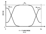
階調レンジ圧縮部172は、入力された照明成分のみの画像データの各画素の輝度値を、例えば入出力レベルの対応を示すルックアップテーブル(LUT)に従って変換し、階調レンジを圧縮する。具体的には、次の図6にも示すように、照明成分の低輝度側の領域に対してはゲインを1より大きくして増幅し、高輝度側の領域に対してはゲインを1未満としてレベルを低減する。
The gradation
反射率成分抽出部173は、入力されたHDR画像から反射率成分を抽出する。例えば、入力されたHDR画像のデータから、照明成分抽出部171で抽出された照明成分のデータを減算することで、反射率成分を求める。あるいは、入力されたHDR画像のデータから照明成分のデータを除算してもよい。階調レンジ伸張部174は、抽出された反射率成分の輝度値を、例えば入出力レベルの対応を示すLUTなどに従って画素ごとに変換し、階調レンジを伸張させる。
The reflectance
合成部175は、階調レンジ圧縮部172および階調レンジ伸張部174からそれぞれ出力された画像データを画素ごとに合成し、全体として階調レンジが圧縮されたHDR画像を出力する。例えば、反射率成分抽出部173において、入力画像データから照明成分のデータを減算することで反射率成分のデータが求められた場合、合成部175では、階調レンジ圧縮部172および階調レンジ伸張部174から出力された各画像データを加算することで合成処理を行う。また、反射率成分抽出部173において、入力画像データから照明成分のデータを除算することで反射率成分のデータが求められた場合、合成部175では、階調レンジ圧縮部172および階調レンジ伸張部174から出力された各画像データを乗算することで合成処理を行う。
The synthesizing
ビット圧縮部176は、合成部175で合成されたHDR画像のデータのビット数を圧縮する。例えば、合成部175から出力されるHDR画像のデータが15ビットデータであるとき、このRAW画像データを、現像処理部17で処理可能な12ビットデータに変換する。
The
図6は、HDR画像の階調レンジ圧縮時に設定されるゲインカーブの例を示す図である。
図6において、a(x,y)は、照明成分抽出部171においてローパスフィルタ処理が施されて抽出された照明成分の画素ごとの輝度値を示す。階調レンジ圧縮部172は、図6(A)に示すように、照明成分の各画素のデータに対して、輝度が低いほど入力レベルを増幅し、輝度が高いほど入力レベルを圧縮する。これにより、全体として階調レンジが圧縮される。
FIG. 6 is a diagram illustrating an example of a gain curve set at the time of gradation range compression of an HDR image.
In FIG. 6, a (x, y) indicates a luminance value for each pixel of the illumination component extracted by performing the low-pass filter processing in the illumination
一方、階調レンジ伸張部174では、最も基本的には、照明成分の輝度値に応じて階調レンジ圧縮部172と同じゲインが反射率成分に対して与えられればよい。これにより、照明成分が暗い領域において反射率成分のレベル(振幅)が増幅されるので、この領域における反射率成分がゲイン印加前に対して相対的に強調され、結果的に階調レンジが伸張される。反射率成分は、ディテールの再現性に大きく寄与する成分であるので、上記のゲインが与えられることで、暗部に埋もれていたディテール成分が強調される。従って、ディテール成分をできるだけ失うことなく、全体の階調レンジを圧縮することが可能になり、このような階調レンジ圧縮後の画像データをビット圧縮部176においてビット圧縮したとき、その画質を向上させることができる。
On the other hand, in the gradation
さらに、図5に示した構成では、照明成分と反射率成分のそれぞれに対応する階調レンジ圧縮部172および階調レンジ伸張部174を個別に設けており、この構成により照明成分と反射率成分のそれぞれに個別のゲインカーブを適用できるようになっている。これにより、照明成分の明るさ分布の任意の領域において、ディテールの再現性を高めることも可能になる。
Further, in the configuration shown in FIG. 5, a gradation
この場合の好適な例としては、反射率成分に対しては、照明成分の低輝度領域に対応する画素に対して照明成分より高いゲインを印加することで、低輝度領域におけるディテール成分をさらに強調することができる。図6では、反射率成分に対しては、まず図6(A)に示す照明成分と共通のゲインカーブを印加した後、さらに図6(B)に示すゲインカーブを印加する例を示している。このようなゲインカーブを適用することにより、照明成分の階調レンジ圧縮量を必要最小限にして、画像全体のコントラスト感を維持しつつ、ディテールの再現性を高めることができる。 As a preferred example in this case, for the reflectance component, a higher gain than the illumination component is applied to the pixel corresponding to the low-luminance region of the illumination component, thereby further enhancing the detail component in the low-luminance region can do. FIG. 6 shows an example in which a gain curve common to the illumination component shown in FIG. 6A is first applied to the reflectance component, and then a gain curve shown in FIG. 6B is further applied. . By applying such a gain curve, it is possible to increase the detail reproducibility while maintaining the contrast of the entire image while minimizing the gradation range compression amount of the illumination component.
なお、図6に示したゲインカーブにおいて、輝度Y1〜Y3は固定値としてあらかじめ用意されていてもよいが、これらを入力画像の信号解析結果から演算により求めてもよい。例えば、輝度Y1,Y2,Y3を、それぞれ後の図13において説明する輝度Yl,Ym,Yhとし、これらの値を照明成分の解析結果を基に演算してもよい。 In the gain curve shown in FIG. 6, the luminances Y1 to Y3 may be prepared in advance as fixed values, but these may be obtained by calculation from the signal analysis result of the input image. For example, the luminance values Y1, Y2, and Y3 may be set as the luminance values Y1, Ym, and Yh described later in FIG. 13, and these values may be calculated based on the analysis result of the illumination component.
なお、図5では、階調レンジの圧縮前のHDR画像における輝度ごとの度数を示すヒストグラム177と、圧縮後のHDR画像における同様のヒストグラム178の各例を示している。これらのヒストグラム177および178によれば、階調レンジ圧縮後のHDR画像データでは、データが存在する輝度のレンジ(すなわち階調レンジ)が狭くなっているとともに、中間から低域側領域の輝度成分を持つ画素が増加し、この輝度領域における階調性が豊かになっていることがわかる。
FIG. 5 shows examples of a
また、この図5の説明では、照明成分の抽出にローパスフィルタを用いているが、後の第3の実施の形態において説明する、レンズのデフォーカス状態における撮像画像を用いる手法により、画像の照明成分を抽出してもよい。これにより、照明成分抽出用のローパスフィルタ回路を省略でき、回路規模を抑制できる。この手法を用いる場合には、例えば、ブラケット撮像後にデフォーカス状態にして、そのときの画像(デフォーカス画像)を取得すればよい。また、ステップS101に対応するプレビュー状態において、定期的にデフォーカス状態の画像を取得し、最新のデフォーカス画像を常にバッファメモリ15などに保持しておいて、シャッタボタン全押し後の階調レンジ圧縮処理時にこのデフォーカス画像を利用してもよい。あるいは、ステップS103でローパスフィルタ処理を施した画像をデフォーカス画像として取得した場合には、この画像データを保持しておいて、照明成分として利用してもよい。プレビュー状態において取得した画像データ、およびステップS103で取得した画像データのいずれを利用する場合も、シャッタラグを短縮することができる。
In the description of FIG. 5, the low-pass filter is used for extraction of the illumination component. However, the illumination of the image is performed by using the captured image in the defocused state of the lens, which will be described later in the third embodiment. Components may be extracted. Thereby, the low-pass filter circuit for extracting illumination components can be omitted, and the circuit scale can be suppressed. When this method is used, for example, a defocus state may be obtained after bracket imaging and an image at that time (defocus image) may be acquired. Further, in the preview state corresponding to step S101, a defocused image is periodically acquired, the latest defocused image is always held in the
以下、図2に戻って説明する。
[ステップS114]階調レンジ圧縮後のHDR画像データは現像処理部17で現像され、HDR画像のJPEGデータとして記録部18に保存される。上述したように、本実施の形態に適用している現像処理部17の現像処理(データ補間、色調整・変換、圧縮符号化処理)の機能は、1回露光での撮像により得られた1枚の画像のデータを処理する仕様になっている。この画像データは例えば12ビットデータとなっており、ステップS105およびS108においてそれぞれ得られる画像データ、および、ステップS111のブラケット撮像時に得られる各画像のデータに相当する。
Hereinafter, the description will be returned to FIG.
[Step S114] The HDR image data after gradation range compression is developed by the
これに対して、ステップS112の処理により合成されたHDR画像のデータは、現像処理部17で現像処理可能な画像データよりもビット数が多くなっており、例えば15ビットデータとなっている。しかし、ステップS113の処理により良好な画質を保ったまま階調レンジを圧縮して、12ビットの画像データに変換することにより、現像処理部17の回路構成を変更することなく、現像処理を施すことができるようになる。
On the other hand, the HDR image data synthesized by the process of step S112 has more bits than image data that can be developed by the
なお、ここでは、図5における合成部175による合成後のHDR画像のデータを、ビット圧縮部176で低ビット化してから、現像処理を施すようにしているが、現像処理部17における処理可能なビット数に余裕がある場合には、ビット圧縮を行わずに現像処理し、その処理の過程で表示デバイスなどに適合可能なビット数(ここでは8ビット)の画像データに変換してもよい。
Here, the HDR image data after being synthesized by the synthesizing
また、この処理例では、撮像時にHDR画像をJPEGデータとして記録するようにしているが、その他に例えば、撮像時においては、合成処理部16からのHDR画像データを、現像処理部17を介することなく、RAW画像データとして記録部18に記録しておき、その後にこのRAW画像データを読み出して、現像処理部17で階調レンジ圧縮・現像処理を施すようにしてもよい。
In this processing example, the HDR image is recorded as JPEG data at the time of imaging. However, for example, at the time of imaging, the HDR image data from the
また、以上の処理例では、画角の変化や被写体の動きがある場合、ステップS112の合成処理により適切な画像を生成できない可能性がある。そこで、ステップS112で合成されたHDR画像のデータをRAW画像データとして記録部18に保存する際に、それに加えて基準画像P0のデータを通常のダイナミックレンジを持つRAW画像データとしてともに保存しておいてもよい。また、撮像時に合成後のHDR画像をJPEGデータとして保存する場合にも、同様に基準画像P0のデータをJPEGデータとして保存しておいてもよい。 In the above processing example, if there is a change in the angle of view or the movement of the subject, there is a possibility that an appropriate image cannot be generated by the composition processing in step S112. Therefore, when saving the recording unit 18 the data of the combined HDR image at step S112 as RAW image data, both to save the data of the reference image P 0 in addition to the RAW image data with normal dynamic range It may be left. Also, when the combined HDR image is saved as JPEG data at the time of imaging, the data of the reference image P 0 may be similarly saved as JPEG data.
以上説明した第1の実施の形態では、露出補正値を徐々に変化させて露光し、得られた画像からその都度、白飛び画素や黒つぶれ画素の有無を判断して、シーンの最高輝度および最低輝度を測定し、その測定結果からブラケット時の露出補正値を決定するようにしたことで、輝度レンジが広く、露光条件を決めるのが困難なシーンでも、適正な露光条件を設定できる確率が高くなる。また、このようなシーンの状況に応じた適正な露出補正値をユーザ操作に依らず、自動的に決定できるようになり、ユーザの操作性が向上する。 In the first embodiment described above, exposure is performed by gradually changing the exposure correction value, and the presence or absence of a whiteout pixel or a blackout pixel is determined from the obtained image each time, and the maximum luminance of the scene and By measuring the minimum brightness and determining the exposure compensation value at the time of bracketing from the measurement result, there is a probability that appropriate exposure conditions can be set even in a scene where the brightness range is wide and it is difficult to determine the exposure conditions Get higher. Further, it becomes possible to automatically determine an appropriate exposure correction value according to the situation of such a scene without depending on the user operation, and the operability for the user is improved.
さらに、最高輝度および最低輝度の測定結果から、ブラケット撮像が必要か否かの判断、および、ブラケット撮像時に必要な露光回数の判断をそれぞれ正確に行うことができるので、無駄な露光が防止され、シャッタラグを必要最小限に抑制することができる。また、各画像の撮像タイミングの時間差が最小限に抑えられるので、画像間の被写体の変化が最小限に留められ、合成後のHDR画像の画質劣化を抑制できる。 Furthermore, from the measurement results of the maximum luminance and the minimum luminance, it is possible to accurately determine whether bracket imaging is necessary and to determine the number of exposures required at the time of bracket imaging, thereby preventing unnecessary exposure, The shutter lag can be suppressed to the minimum necessary. In addition, since the time difference between the image capturing timings of the images is minimized, the change in the subject between the images is minimized, and deterioration of the image quality of the HDR image after synthesis can be suppressed.
また、シーンの輝度レンジを測定する際に、ローパスフィルタ処理を施した後の撮像画像データからの検波値を用いることで、入力画像に極端に明るい小領域や極端に暗い小領域が含まれた場合にも、測定アルゴリズムが攪乱されて適正な画像を撮像できなくなる事態を防止できる。 Also, when measuring the luminance range of the scene, using the detection value from the captured image data after low-pass filter processing, the input image contained extremely bright small areas or extremely dark small areas Even in this case, it is possible to prevent a situation in which the measurement algorithm is disturbed and an appropriate image cannot be captured.
また、ステップS112に示したHDR画像の合成手法により、ブラケット撮像により得られた複数の画像から、違和感のない自然なHDR画像を合成できる。特に、上記のように適正な露出補正値を用いてブラケット撮像を行うことで得られた画像から、1枚のHDR画像が合成されることで、一層高画質なHDR画像を生成することが可能になる。さらに、ステップS113の階調レンジ圧縮の手法により、その後に画像データのビット数を低減した際にも、画像のディテール成分を損なうことなく高い画質を維持できるようになる。以上の処理により、汎用フォーマットに変換された高画質のHDR画像を得ることができる。 Moreover, a natural HDR image without a sense of incongruity can be synthesized from a plurality of images obtained by bracket imaging by the HDR image synthesis method shown in step S112. In particular, it is possible to generate a higher quality HDR image by synthesizing one HDR image from an image obtained by performing bracket imaging using an appropriate exposure correction value as described above. become. Furthermore, even when the number of bits of the image data is subsequently reduced by the gradation range compression method in step S113, high image quality can be maintained without impairing the image detail components. Through the above processing, a high-quality HDR image converted into a general-purpose format can be obtained.
〔第2の実施の形態〕
上述した第1の実施の形態では、図2のステップS106において、実際の露光条件を変化させることで、高輝度側および低輝度側での適正な露出補正値を計測し、その計測結果に応じて、ステップS107においてブラケット撮像が必要か否かを判定していた。これに対して、以下で説明する第2の実施の形態では、撮像動作を迅速に行ってシャッタラグを抑制するために、これらの手順に代えて、ステップS103での輝度値の検波結果を直接利用して、シーンの輝度レンジを推定する。この第2の実施の形態では、ステップS103で検波した輝度値と、輝度値ごとの度数を示すヒストグラム値を累積した累積ヒストグラムを基に、シーンの輝度レンジを推定する。
[Second Embodiment]
In the first embodiment described above, appropriate exposure correction values on the high luminance side and the low luminance side are measured by changing the actual exposure conditions in step S106 of FIG. 2, and according to the measurement result. In step S107, it is determined whether bracket imaging is necessary. On the other hand, in the second embodiment described below, instead of these procedures, the detection result of the luminance value in step S103 is directly used in order to quickly perform the imaging operation and suppress the shutter lag. Then, the luminance range of the scene is estimated. In the second embodiment, the luminance range of the scene is estimated based on the cumulative histogram obtained by accumulating the luminance value detected in step S103 and the histogram value indicating the frequency for each luminance value.
図7は、累積ヒストグラムから求められるパラメータを説明するための図である。
図7に示す累積ヒストグラムでは、すべての輝度に対応するヒストグラム値の累積値を、縦軸の最大値(100%)としている。なお、図7において、Y’DL、Y’DHは、それぞれ撮像素子12によって検出可能な最低、最高の輝度値を示す。本実施の形態では、このような累積ヒストグラムを基に、「キーレベル」、「ハイライトレベル」、および「シャドウレベル」の3種類のパラメータを用いて、推定されるシーンの状態を分類し、その分類結果に応じて露出補正の段数を決定する。
FIG. 7 is a diagram for explaining parameters obtained from the cumulative histogram.
In the cumulative histogram shown in FIG. 7, the cumulative value of the histogram values corresponding to all the luminances is the maximum value (100%) on the vertical axis. In FIG. 7, Y ′ DL and Y ′ DH indicate the lowest and highest luminance values that can be detected by the image sensor 12, respectively. In the present embodiment, based on such a cumulative histogram, the estimated scene state is classified using three types of parameters, “key level”, “highlight level”, and “shadow level”. The number of exposure correction steps is determined according to the classification result.
キーレベルとは、主要な被写体が存在している可能性の高い累積度数のレベル(割合)をしきい値ThMとして設定したとき、累積ヒストグラムがどの輝度領域でしきい値ThHに達するかを示すものである。この例では、輝度領域をLow、Mid、Highの3段階に分割し、この3段階の領域によりキーレベルを表す。なお、このようなしきい値は通常、累積度数が50%以上のレベルにあることが知られ、例えば65%〜75%程度に設定することができる。 The key level is the luminance region in which the cumulative histogram reaches the threshold value Th H when the level (proportion) of the cumulative frequency at which the main subject is likely to exist is set as the threshold value Th M. Is shown. In this example, the luminance area is divided into three stages of Low, Mid, and High, and the key level is represented by the three stages. Such a threshold is generally known to have a cumulative frequency of 50% or more, and can be set to, for example, about 65% to 75%.
ハイライトレベルとは、主要な被写体に対応する累積度数より高いレベルにしきい値ThHを設定したとき、累積ヒストグラムがどの輝度領域でしきい値ThHに達するかを示すものである。また、シャドウレベルとは、主要な被写体に対応する累積度数より低いレベルにしきい値ThLを設定したとき、累積ヒストグラムがどの輝度領域でしきい値ThLに達するかを示すものである。ハイライトレベルおよびシャドウレベルは、ともにLow、Mid、Highの3段階に分割された輝度領域によって表される。 The highlight level indicates in which luminance region the cumulative histogram reaches the threshold Th H when the threshold Th H is set to a level higher than the cumulative frequency corresponding to the main subject. The shadow level indicates in which luminance region the cumulative histogram reaches the threshold Th L when the threshold Th L is set to a level lower than the cumulative frequency corresponding to the main subject. Both the highlight level and the shadow level are represented by luminance areas divided into three stages of Low, Mid, and High.
ここで、累積ヒストグラムに基づく各パラメータの組み合わせに応じて露出補正値を決定するためのテーブルの例を、以下に示す。EVUNDER決定テーブルは、シーンの高輝度側での適正な露出補正値EVUNDERを決めるためのテーブルである。また、EVOVER決定テーブルは、シーンの低輝度側での適正な露出補正値EVOVERを決めるためのテーブルである。マイクロコンピュータ20は、上述した3つのパラメータを求めた後、これらの各テーブルに従って、ブラケット撮像時における露出補正値EVUNDERおよびEVOVERを決定する。
Here, an example of a table for determining an exposure correction value according to a combination of parameters based on the cumulative histogram is shown below. The EV UNDER determination table is a table for determining an appropriate exposure correction value EV UNDER on the high luminance side of the scene. The EV OVER determination table is a table for determining an appropriate exposure correction value EV OVER on the low luminance side of the scene. After obtaining the above three parameters, the
上記の各テーブルでは、露出補正値を、基準画像P0での露出制御値を基準とした補正段数で示しており、補正段数の1段に相当する露出補正値はあらかじめ決められているものとする。また、補正段数が0となる場合には、その補正段数を適用した露光動作を行わない。これにより、ブラケット撮像時の露光回数を必要最小限とし、シャッタラグを短縮できる。 In each of the above tables, the exposure correction value is indicated by the number of correction steps based on the exposure control value in the reference image P 0 , and the exposure correction value corresponding to one of the correction steps is determined in advance. To do. Further, when the number of correction steps is 0, the exposure operation using the number of correction steps is not performed. As a result, the number of exposures during bracket imaging can be minimized and the shutter lag can be shortened.
さらに、これらのテーブルでは、高輝度側の適正補正段数の決定時、および低輝度側の適正補正段数の決定時において、それぞれ白飛び画素、黒つぶれ画素が存在しない場合には、HDR画像の撮像の必要がないと判定して補正段数を0とし、その補正段数を適用した露光動作を行わないようにしている(図2のステップS104の判定処理に対応)。また、高輝度側および低輝度側の適正補正段数がともに0の場合には、ブラケット撮像の必要がないと判断する(図2のステップS107の判定処理に対応)。 Further, in these tables, when there is no whiteout pixel or blackout pixel at the time of determining the appropriate number of correction steps on the high luminance side and at the time of determining the appropriate number of correction steps on the low luminance side, an HDR image is captured. Therefore, the number of correction steps is set to 0, and the exposure operation using the number of correction steps is not performed (corresponding to the determination process in step S104 in FIG. 2). Further, when the appropriate correction steps on the high luminance side and the low luminance side are both 0, it is determined that bracket imaging is not necessary (corresponding to the determination process in step S107 in FIG. 2).
図8は、キーレベルとハイライトレベルの組み合わせに対応する輝度値の度数を示すヒストグラムの代表的な例を示す図である。
この図8に示すように、キーレベルのしきい値ThMと、それより高いしきい値ThHとを用いてシーンを分類することで、輝度値の分布に偏りがある場合でも、適正な補正段数を簡単かつ正確に決定することができる。このことは、低輝度側での適正な補正段数を決定する際でも同様である。
FIG. 8 is a diagram illustrating a representative example of a histogram indicating the frequency of the luminance value corresponding to the combination of the key level and the highlight level.
As shown in FIG. 8, by classifying scenes using the threshold value Th M of the key level and the higher threshold value Th H , even if there is a bias in the distribution of luminance values, an appropriate value is obtained. The number of correction steps can be determined easily and accurately. The same applies to the determination of an appropriate number of correction steps on the low luminance side.
以上の第2の実施の形態では、ブラケット撮像時の適正露出補正値を決定するために、第1の実施の形態のように、実際に露出補正値を変化させて露光してその都度検波値を得る必要がないので、適正露出補正値の決定に要する時間を短縮し、シャッタラグを短縮してユーザに快適な操作性をもたらすことができる。また、マイクロコンピュータ20の演算処理が簡略化され、その処理負荷を軽減することができる。
In the second embodiment described above, in order to determine an appropriate exposure correction value at the time of bracket imaging, exposure is performed by actually changing the exposure correction value and performing detection each time as in the first embodiment. Therefore, it is possible to shorten the time required to determine the appropriate exposure correction value and shorten the shutter lag, thereby bringing a comfortable operability to the user. Moreover, the arithmetic processing of the
なお、本実施の形態では、例として、シーンの分類のためのパラメータを、キーレベル以外に高輝度側、低輝度側についてそれぞれ1つずつ設定したが、それぞれに対して複数のパラメータを設定してさらにシーンを細かく分類し、それらの分類に応じて露出補正値をより細かく調整してもよい。これにより、適正露出補正値の推定精度を高めることができる反面、マイクロコンピュータ20による処理負荷は高くなる。
In this embodiment, as an example, one parameter for scene classification is set for each of the high luminance side and the low luminance side in addition to the key level, but a plurality of parameters are set for each. The scenes may be further classified and the exposure correction value may be adjusted more finely according to the classification. Thereby, the estimation accuracy of the appropriate exposure correction value can be increased, but the processing load by the
〔第3の実施の形態〕
本発明の第3の実施の形態では、上記各実施の形態に示したブラケット撮像により得た複数の画像を基に、内挿補間を施すことによって、表示デバイスなどへ出力可能な画像データと同じビット数(ここでは8ビット)を持つHDR画像を直接的に生成する。
[Third Embodiment]
In the third embodiment of the present invention, the same image data that can be output to a display device or the like by performing interpolation on the basis of a plurality of images obtained by bracket imaging shown in the above embodiments. An HDR image having a bit number (here, 8 bits) is directly generated.
図9は、第3の実施の形態に係るDSCの内部構成を示すブロック図である。なお、この図9では、図1に対応するブロックについては同じ符号を付して示し、その説明を省略する。 FIG. 9 is a block diagram showing an internal configuration of the DSC according to the third embodiment. In FIG. 9, blocks corresponding to FIG. 1 are denoted by the same reference numerals and description thereof is omitted.
図9に示すDSCは、図1に示したDSCの構成に加えて、デフォーカス画像のデータを保持するためのバッファメモリ23と、重み係数生成処理部24と、補間処理部25を備える。なお、図9において、現像処理部17aは、図1に示す現像処理部17の機能のうち、画像圧縮符号化機能を除いた機能を持ち、その画像圧縮符号化機能は、符号化処理部17bとして補間処理部25の後段に接続される。また、バッファメモリ15aは、ブラケット撮像により得られた画像のデータを一時的に保持するが、この際に、ISOゲイン調整部14ではなく現像処理部17aから出力された画像データの供給を受ける。
The DSC shown in FIG. 9 includes a
バッファメモリ23は、デフォーカス状態で露光されたときに得られた画像データを、ISOゲイン調整部14から受けて一時的に格納する。重み係数生成処理部24は、バッファメモリ23に格納された画像データを基に、ブラケット撮像により得られた画像の合成時に用いる重み係数を生成する。補間処理部25は、ブラケット撮像により得られた画像データをバッファメモリ15aから読み出し、重み係数生成処理部24から供給された重み係数を用いて、各画像データを合成する。このときに出力されるHDR画像のデータは、第1の実施の形態における合成後のHDR画像のデータとは異なり、現像処理部17aで処理された画像データと同じビット数(8ビット)を持つことになり、その後に表示部19に供給してHDR画像を表示させたり、符号化処理部17bに供給してJPEGデータとして出力することが可能になる。
The
図10は、第3の実施の形態に係るDSCでの撮像時の処理手順を示すフローチャートである。
本実施の形態においては、HDR画像の撮像を行うか否か(図2のステップS104)、およびブラケット撮像が必要か否か(ステップS107)を判定する処理までは、第1の実施の形態の場合と同様の処理が行われる。従って、図10では、ステップS107でブラケット撮像が必要と判定された場合以降の処理についてのみ示す。なお、シーンの輝度レンジの判別(ステップS106)およびブラケット撮像の要否の判定(ステップS107)の各処理では、第1の実施の形態の処理手順の代わりに、第2の実施の形態の処理手順を適用することも可能である。
FIG. 10 is a flowchart illustrating a processing procedure at the time of imaging in the DSC according to the third embodiment.
In the present embodiment, the process up to the process of determining whether or not to capture an HDR image (step S104 in FIG. 2) and whether or not bracket imaging is necessary (step S107) is the same as in the first embodiment. The same processing as in the case is performed. Therefore, FIG. 10 shows only processing after the case where it is determined in step S107 that bracket imaging is necessary. In each process of determining the luminance range of the scene (step S106) and determining whether bracket imaging is necessary (step S107), the process of the second embodiment is used instead of the process procedure of the first embodiment. It is also possible to apply a procedure.
[ステップS301]このステップでは、図3のステップS201と同じ処理が行われる。すなわち、マイクロコンピュータ20は、ステップS106で測定された最高輝度YHおよび最低輝度YLを用いて、上記の式(3)および(4)に従って、シーンの高輝度側および低輝度側での各露出補正値EVUNDERおよびEVOVERを計算する。
[Step S301] In this step, the same processing as step S201 in FIG. 3 is performed. In other words, the
[ステップS302]マイクロコンピュータ20は、図2のステップS101で推定した(またはステップS103であらためて推定した)露出制御値をそのまま補正せずに用いて、露光動作を実行させ、基準画像P0を撮像する。また、得られた基準画像P0のデータは、現像処理部17aで現像され、現像後の基準画像P’0のデータはバッファメモリ15aに一旦格納される。
[Step S302] The
[ステップS303]マイクロコンピュータ20は、露出補正値EVUNDERが0であるか否かを判定する。0である場合はステップS305の処理が実行され、0でない場合はステップS304の処理が実行される。
[Step S303] The
[ステップS304]露出補正値EVUNDERが0でなければ、マイクロコンピュータ20は、この露出補正値EVUNDERを適用して、露光動作を実行させる。また、得られた画像PUNDERのデータは、現像処理部17aで現像され、現像後の画像P’UNDERのデータがバッファメモリ15aに一旦格納される。
[Step S304] If the exposure correction value EV UNDER is not 0, the
[ステップS305]マイクロコンピュータ20は、露出補正値EVOVERが0であるか否かを判定する。0である場合はステップS307の処理が実行され、0でない場合はステップS306の処理が実行される。
[Step S305] The
[ステップS306]露出補正値EVOVERが0でなければ、マイクロコンピュータ20は、この露出補正値EVOVERを適用して、露光動作を実行させる。また、得られた画像POVERのデータは、現像処理部17aで現像され、現像後の画像P’OVERのデータがバッファメモリ15aに一旦格納される。
[Step S306] If the exposure correction value EV OVER is not 0, the
なお、ステップS302,S304,S306における現像処理では、マイクロコンピュータ20の処理により、それぞれ対象の画像から個別に推定された制御値が用いられればよい。
In the development processing in steps S302, S304, and S306, it is only necessary to use control values that are individually estimated from the target image by the processing of the
[ステップS307]次に、マイクロコンピュータ20の制御により、補間処理部25で適用される重み係数を得るために必要な、撮像画像の照明成分を生成する処理が実行される。
[Step S307] Next, under the control of the
照明成分は、一般的に、撮像画像に対してカットオフ周波数を比較的低くしたローパスフィルタ処理を施すことで得ることができるが、このためにはタップ数の多いフィルタ回路が必要であり、演算量が膨大になってしまうという問題があった。これに対して、本実施の形態では、そのようなフィルタ回路を利用する代わりに、光学ブロック11内のフォーカス調整レンズを制御してデフォーカス状態とし、その状態で露光して得た画像(デフォーカス画像)を、ローパスフィルタ処理された画像(ローパス画像)として利用する。これにより回路規模を削減する。 In general, the illumination component can be obtained by applying low-pass filter processing with a relatively low cut-off frequency to the captured image, but this requires a filter circuit with a large number of taps. There was a problem that the amount would be enormous. In contrast, in this embodiment, instead of using such a filter circuit, the focus adjustment lens in the optical block 11 is controlled to be in a defocused state, and an image (defocused) obtained by exposure in that state is used. Focus image) is used as a low-pass filtered image (low-pass image). This reduces the circuit scale.
ここでは、まず、ステップS302,S304,S306でのブラケット撮像時の露光条件のうち、中央の露光条件となるように露光制御を行う。このとき、次の式(6)を満たすように、シャッタスピードSとISOゲインGとを決める。 Here, first, exposure control is performed so that the exposure condition at the center is the exposure condition at the time of bracket imaging in steps S302, S304, and S306. At this time, the shutter speed S and the ISO gain G are determined so as to satisfy the following expression (6).
ここで、FMINは開放絞り値を表し、S0,F0,G0は、上述したブラケット撮像時における中央の露光条件でのシャッタスピード、絞り値、ISOゲインをそれぞれ示す。この式(6)を適用することにより絞りが開放されるので、被写界深度が浅くなって、デフォーカス時のローパスフィルタ効果を強くすることができる。 Here, F MIN represents an open aperture value, and S 0 , F 0 , and G 0 represent a shutter speed, an aperture value, and an ISO gain, respectively, under the central exposure conditions during the bracket imaging described above. By applying this formula (6), the aperture is opened, so that the depth of field becomes shallow, and the low-pass filter effect at the time of defocusing can be strengthened.
次に、上記の手法で決められたシャッタスピードSとISOゲインGとを適用して露光を行い、デフォーカス画像を撮像する。ここでは、強いローパスフィルタ効果を確実に得るために、フォーカス調整レンズの位置を変えて2枚のデフォーカス画像を撮像し、後のステップS308の処理によりこれらの平均をとり、ローパス画像を生成する。 Next, exposure is performed by applying the shutter speed S and ISO gain G determined by the above method, and a defocused image is captured. Here, in order to surely obtain a strong low-pass filter effect, two defocused images are picked up by changing the position of the focus adjustment lens, and the average of these is taken by the subsequent processing in step S308 to generate a low-pass image. .
図11は、デフォーカス画像の撮像時におけるフォーカス調整レンズの駆動手順を説明するための図である。
図11では、光学ブロック11における光学レンズ群11cの構成例と、その中でのフォーカス調整レンズ11dの位置の例とを示している。ここでは、マクロ撮像モードを備えた場合を例に挙げている。なお、各図では、右側を撮像素子12の撮像面12aとしている。また、この光学レンズ群11cのレンズ構成および各レンズの位置は、あくまで一例である。
FIG. 11 is a diagram for explaining a driving procedure of the focus adjustment lens when a defocus image is captured.
FIG. 11 shows a configuration example of the
同図(A)では、無限遠側の撮像時におけるフォーカス調整レンズ11dの位置の例を示している。また、同図(B)では、同様にマクロ側の撮像時におけるフォーカス調整レンズ11dの位置の例を示している。ここで、無限遠側の撮像時とマクロ側の撮像時とでは、デフォーカス状態としたときに画像のボケの傾向が逆になることが知られている。このため、一方の撮像状態のみからデフォーカス状態としても、必ずしも強いローパスフィルタ効果が得られない場合がある。例えば、マクロ側の撮像でピントが合ってしまい、ローパスフィルタ効果が弱まるような被写体に対しては、無限遠側の撮像時にはピントのずれが大きくなり、強いローパスフィルタ効果が得られる。
FIG. 4A shows an example of the position of the
そこで、本実施の形態では、マイクロコンピュータ20の制御により、無限遠側の撮像時の状態とマクロ側の撮像時の状態の両方からデフォーカス状態を作り出し、各状態で露光して2枚のデフォーカス画像を得る。具体的には、まず、同図(C)のように、無限遠側の撮像時の状態から、フォーカス調整レンズ11dをさらに遠端側に変位させて露光し、得られたデフォーカス画像のデータをバッファメモリ23に格納する。次に、同図(D)のように、マクロ側の撮像時の状態から、フォーカス調整レンズ11dをさらに近端側に変位させて露光し、得られたデフォーカス画像のデータをバッファメモリ23に格納する。
Therefore, in the present embodiment, under the control of the
次に、重み係数生成処理部24(あるいはマイクロコンピュータ20)の処理により、バッファメモリ23から2つのデフォーカス画像のデータを読み出し、これらを平均してローパス画像のデータとする。このような処理により、ローパスフィルタ効果が弱まることが防止できる。なお、生成されたローパス画像のデータは、バッファメモリ23に格納しておく。
Next, two defocus image data are read from the
以下、図10に戻って説明する。
[ステップS308]重み係数生成処理部24(あるいはマイクロコンピュータ20)は、生成されたローパス画像のデータを解析し、このローパス画像に不要な高周波成分が残っているか否かを判定する。残っている場合はステップS309の処理が実行され、残っていない場合はステップS310の処理が実行される。
Hereinafter, the description will be returned to FIG.
[Step S308] The weight coefficient generation processing unit 24 (or the microcomputer 20) analyzes the generated low-pass image data and determines whether or not an unnecessary high-frequency component remains in the low-pass image. If it remains, the process of step S309 is executed, and if it does not remain, the process of step S310 is executed.
[ステップS309]ローパス画像に不要な高周波成分が残っている場合、重み係数生成処理部24(あるいはマイクロコンピュータ20)は、ローパス画像のデータに対して、例えば5タップ×5タップ程度の比較的小さなタップ数のローパスフィルタ処理を施す。処理後のデータは、バッファメモリ23に格納しておく。
[Step S309] When unnecessary high-frequency components remain in the low-pass image, the weight coefficient generation processing unit 24 (or the microcomputer 20) is relatively small, for example, about 5 taps × 5 taps with respect to the low-pass image data. Apply low-pass filter processing for the number of taps. The processed data is stored in the
[ステップS310]重み係数生成処理部24は、バッファメモリ23に格納されたローパス画像のデータを基に重み係数を求め、補間処理部25に供給する。このとき、重み係数生成処理部24は、後の図12に示すような、ローパス画像の輝度と重み係数との変換関数に従って、重み係数を求める。補間処理部25は、その重み係数を用いて、ステップS302,S304,S306で得られ、バッファメモリ15aに格納されていた画像データを内挿補間により合成し、1枚のHDR画像のデータを生成する。
[Step S <b> 310] The weighting factor
ここで、図12は、ローパス画像の輝度を重み係数に変換するための変換関数の例を示す図である。
図12において、重み係数w0は、ステップS302で現像された基準画像P’0を補間処理部25において内挿補間する際の補間係数である。同様に、重み係数wUNDERおよびwOVERは、それぞれステップS304およびS306で現像された画像P’UNDERおよびP’OVERを補間処理部25において内挿補間する際の補間係数である。
Here, FIG. 12 is a diagram illustrating an example of a conversion function for converting the luminance of the low-pass image into a weighting coefficient.
In FIG. 12, a weighting factor w 0 is an interpolation factor used when the
重み係数生成処理部24は、バッファメモリ23から読み出したローパス画像の各画素の輝度データa(x,y)に応じて、上記の変換関数を参照して重み係数w0,wUNDER,wOVERを出力する。補間処理部25は、重み係数生成処理部24からの重み係数w0,wUNDER,wOVERを用いて、次の式(7)に従って、バッファメモリ15a内の基準画像P’0、画像P’UNDERおよびP’OVERの各データを合成する。
The weight coefficient
この式(7)において、P’(x,y)は、合成後の画像P’の各画素のデータを示し、P’n(x,y)は、バッファメモリ15aに格納された画像P’n(すなわち、基準画像P’0、画像P’UNDERおよびP’OVER)のそれぞれの画素のデータを示す。また、wn(a(x,y))は、画像P’nの各画素の合成時に適用される重み係数(すなわち、重み係数w0,wUNDER,wOVER)を示す。 In this equation (7), P ′ (x, y) represents the data of each pixel of the combined image P ′, and P ′ n (x, y) represents the image P ′ stored in the buffer memory 15a. Each pixel data of n (that is, reference image P ′ 0 , image P ′ UNDER and P ′ OVER ) is shown. Further, w n (a (x, y)) indicates a weighting factor (that is, weighting factors w 0 , w UNDER , w OVER ) applied when synthesizing each pixel of the image P ′ n .
このような処理により、被写体のうち、照明光が強く照射された部分に対しては、露出量を抑えた画像が高い比率で合成され、これにより、画像データの階調レンジを高輝度側に拡大することなく、基準画像P0の撮像時に検出できない高輝度領域の階調情報を合成後の画像に取り込むことが可能になる。また、照明光が弱く照射された部分に対しては、露出量を増した画像が高い比率で合成され、これにより、同様に、画像データの階調レンジを低輝度側に拡大することなく、基準画像P0の撮像時に検出できない低輝度領域の階調情報を合成後の画像に取り込むことが可能になる。その結果、現像処理部17aでの処理後の画像データと同じ階調レンジおよびデータビット数(8ビット)を持つHDR画像が生成される。
By such processing, an image with a reduced exposure amount is synthesized at a high ratio for a portion of the subject that is strongly irradiated with illumination light, thereby increasing the gradation range of the image data to the high luminance side. Without enlarging, it is possible to incorporate gradation information of a high-luminance region that cannot be detected when the reference image P 0 is captured into the combined image. In addition, for the portion irradiated with weak illumination light, an image with an increased amount of exposure is combined at a high ratio, thereby, similarly, without expanding the gradation range of the image data to the low luminance side, It is possible to incorporate gradation information of a low luminance area that cannot be detected when the reference image P 0 is captured into the combined image. As a result, an HDR image having the same gradation range and number of data bits (8 bits) as the image data processed by the
また、ブラケット撮像により得られた画像の合成比を、図12の変換関数に従い、撮像画像の照明成分(すなわちローパス画像)の輝度に基づいて決定することにより、輝度レンジの広いシーンにおいて得られた画像データの階調レンジを圧縮するとともに、特にローパス画像の低輝度領域でのディテール成分を強調して、全体の画質を向上させる効果を得ることもできる。 In addition, the composite ratio of the images obtained by bracket imaging was determined in a scene with a wide luminance range by determining based on the luminance of the illumination component of the captured image (that is, the low-pass image) according to the conversion function of FIG. In addition to compressing the gradation range of the image data, it is also possible to obtain an effect of improving the overall image quality by emphasizing detail components particularly in the low-luminance region of the low-pass image.
ところで、図12に示した変換関数については、ローパス画像の特性やブラケット撮像時の各種制御パラメータ、ブラケット撮像により得られた画像の特性などに応じて、設定を変化させることができる。以下、このような変換関数の設定手法について説明する。なお、ここでは例として、変換関数の設定を重み係数生成処理部24が行うものとするが、この処理をマイクロコンピュータ20で行うようにしてもよい。
Incidentally, the setting of the conversion function shown in FIG. 12 can be changed according to the characteristics of the low-pass image, various control parameters at the time of bracket imaging, the characteristics of the image obtained by bracket imaging, and the like. Hereinafter, a method for setting such a conversion function will be described. Here, as an example, the weighting factor
図13は、ローパス画像における輝度値の度数を示すヒストグラムの例である。
まず、重み係数生成処理部24は、バッファメモリ23に記憶されたローパス画像のデータを基に輝度値の度数を示すヒストグラムを計算する。図13にはこのようなヒストグラムの例を示しているが、ここでは、ローパス画像の輝度値を、現像処理部17aで実行されるガンマ補正を施した場合の輝度値に換算してヒストグラムを求めている。重み係数生成処理部24は、求めたヒストグラムから度数がピークとなる輝度YhおよびYlを、輝度レベルの高い順に求める。さらに、輝度YhおよびYlに対応するピーク間に存在するヒストグラムの谷を検出し、それに対応する輝度Ymを求める。なお、ここでは、高輝度側から2番目のピークに対して輝度Ylを対応させているが、それより低輝度側のピーク(例えば最も低輝度側のピーク)に輝度Ylを対応させてもよい。
FIG. 13 is an example of a histogram showing the frequency of the luminance value in the low-pass image.
First, the weight coefficient
次に、重み係数生成処理部24は、バッファメモリ23に格納した基準画像P’0、画像P’UNDERおよびP’OVERの各データを基に、各画像における輝度値の頻度を示すヒストグラムを計算する。ここで、これらのヒストグラムから検出されるパラメータを基に、次の式(8)および(9)に従って、基準画像P’0と画像P’UNDERとの合成画像P’-と、基準画像P’0と画像P’OVERとの合成画像P’+とを考える。ただし、0≦Kh≦1、0≦Kl≦1とする。
P’-=Kh×P’UNDER+(1−Kh)×P’0 ……(8)
P’+=Kl×P’OVER+(1−Kl)×P’0 ……(9)
図14は、基準画像P’0、画像P’UNDERおよびP’OVERの各輝度値に基づくヒストグラムの例を示す図である。
Next, the weight coefficient
P ′ − = Kh × P ′ UNDER + (1−Kh) × P ′ 0 (8)
P ′ + = Kl × P ′ OVER + (1−Kl) × P ′ 0 (9)
FIG. 14 is a diagram illustrating an example of a histogram based on the luminance values of the reference image P ′ 0 , the images P ′ UNDER and P ′ OVER .
同図(A)は、基準画像P’0および画像P’UNDERに対応するヒストグラムの例を示している。この(A)において、輝度Yh_0は、基準画像P’0のヒストグラム上で高輝度側から1番目のピークが存在する輝度値であり、輝度Yh_underは、画像P’UNDERのヒストグラム上で高輝度側から1番目のピークが存在する輝度値である。また、同図(B)は、基準画像P’0および画像P’OVERに対応するヒストグラムの例を示している。この(B)において、輝度Yl_0は、基準画像P’0のヒストグラム上で高輝度側から2番目のピークが存在する輝度値であり、輝度Yl_overは、画像P’OVERのヒストグラム上で高輝度側から2番目のピークが存在する輝度値である。 FIG. 6A shows an example of a histogram corresponding to the reference image P ′ 0 and the image P ′ UNDER . In (A), the luminance Yh_0 is a luminance value in which the first peak from the high luminance side exists on the histogram of the reference image P ′ 0 , and the luminance Yh_under is the high luminance side on the histogram of the image P ′ UNDER. Is the luminance value at which the first peak exists. FIG. 5B shows an example of a histogram corresponding to the reference image P ′ 0 and the image P ′ OVER . In this (B), the luminance Yl_0 is a luminance value where the second peak from the high luminance side exists on the histogram of the reference image P ′ 0 , and the luminance Yl_over is the high luminance side on the histogram of the image P ′ OVER. Is the luminance value where the second peak exists.
ここで、基準画像P’0および画像P’UNDERを式(8)に従って合成した合成画像P’-を考えると、図14(A)に示すように、合成画像P’-のヒストグラムにおける高輝度側から1番目のピークの位置は、重み係数Khが大きいほど低輝度側に変位する。重み係数生成処理部24は、このピークに対応する輝度値が、ローパス画像の輝度範囲(すなわち、ローパス画像中の最高輝度と最低輝度との範囲)の中間値となる輝度Yrmとなるように、重み係数Khを求める。
Here, considering a composite image P ′ − obtained by combining the reference image P ′ 0 and the image P ′ UNDER according to the equation (8), as shown in FIG. 14A, the high luminance in the histogram of the composite image P ′ −. The position of the first peak from the side shifts to the low luminance side as the weighting factor Kh increases. The weighting coefficient
同様に、基準画像P’0および画像P’OVERを式(9)に従って合成した合成画像P’+を考えると、図14(B)に示すように、合成画像P’+のヒストグラムにおける高輝度側から2番目のピークの位置は、重み係数Klが大きいほど高輝度側に変位する。重み係数生成処理部24は、このピークに対応する輝度値が、ローパス画像の輝度範囲の中間値となる輝度Yrmとなるように、重み係数Klを求める。なお、ここでは例として、合成画像P’+のヒストグラムにおける高輝度側から2番目のピークに対応する輝度値を用いているが、それより低輝度側のピーク(例えば最も低輝度側のピーク)に対応する輝度値を用いて演算を行ってもよい。
Similarly, 'considering + a, as shown in FIG. 14 (B), the composite image P' of the reference image P '0 and the image P' OVER synthesized composite image P according to Equation (9) high brightness at + histogram The position of the second peak from the side is shifted to the higher luminance side as the weighting factor Kl is larger. The weighting coefficient
以上の演算により、基準画像P’0に対する画像P’UNDERおよびP’OVERの適切な最大合成比率が求められる。この最大合成比率は、低輝度側および高輝度側の階調レンジの最大圧縮量を規定するものであり、輝度Yrmを基に演算することで、階調レンジの圧縮効果とコントラスト感とのバランスを良好に保つことができる。 Through the above calculation, an appropriate maximum composition ratio of the images P ′ UNDER and P ′ OVER with respect to the reference image P ′ 0 is obtained. This maximum composition ratio defines the maximum compression amount of the gradation range on the low luminance side and the high luminance side. By calculating based on the luminance Yrm, the balance between the compression effect of the gradation range and the contrast feeling. Can be kept good.
次に、このように求めた重み係数KhおよびKlを用い、ローパス画像の輝度に応じて、合成画像P’-およびP’+をブレンドすることを考える。このブレンド処理は、例えば、単調増加関数f(Y)を用いて、次の式(10)に従って実行される。ただし、0≦Kg≦1とする。
P’=(0.5+Kg×f(Y))×P’-+(0.5−Kg×f(Y))×P’+
……(10)
ここで、図15は、単調増加関数f(Y)の例を示す図である。
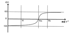
Next, it is considered that blended images P ′ − and P ′ + are blended according to the luminance of the low-pass image using the weighting factors Kh and Kl thus obtained. This blending process is executed according to the following equation (10) using, for example, a monotonically increasing function f (Y). However, 0 ≦ Kg ≦ 1.
P ′ = (0.5 + Kg × f (Y)) × P ′ − + (0.5−Kg × f (Y)) × P ′ +
(10)
Here, FIG. 15 is a diagram illustrating an example of the monotonically increasing function f (Y).
重み係数生成処理部24は、この図15に示すように、f(Ym)が0となり、f(Yh)およびf(Yl)での傾きがともに十分小さくなるように、単調増加関数f(Y)を定義する。この条件と、上述した重み係数KhおよびKlの演算手法とにより、合成処理において、ヒストグラムのピークが存在する輝度領域(すなわち、ローパス画像内で多くの面積を占める輝度領域)に対する階調レンジ圧縮の影響を弱めることができ、その領域におけるグラデーションが失われることを防止して画質を高めることができる。
As shown in FIG. 15, the weight coefficient
さらに、上記の式(10)におけるパラメータKgを変化させることで、合成後の画像P’において表現されるコントラスト感を調節することができる。パラメータKgが1のとき、基準画像P’0に対する画像P’UNDERおよびP’OVERの合成比率が最大になって、階調レンジ圧縮の効果が最大(すなわち、コントラストが最小)になり、パラメータKgが0のとき、コントラストが最大になる。このパラメータKgとしては、例えば、重み係数生成処理部24により、ブラケット撮像時における露出補正量に応じて、あるいは輝度Yhと輝度Ylとの比に応じて、LUTなどを参照して最適な値を決めることができる。例えば、露出補正量が小さいほど、また、Yh/Ylの値が小さいほど、パラメータKgを小さい値とする。また、ユーザの操作入力によりパラメータKgを調整できるようにしてもよい。
Further, by changing the parameter Kg in the above equation (10), it is possible to adjust the contrast feeling expressed in the combined image P ′. When the parameter Kg is 1, the composition ratio of the images P ′ UNDER and P ′ OVER to the reference image P ′ 0 is maximized, and the effect of gradation range compression is maximized (that is, the contrast is minimized), and the parameter Kg When is 0, the contrast is maximized. As this parameter Kg, for example, the weighting coefficient
重み係数生成処理部24は、以上のように求められた重み係数KhおよびKl、単調増加関数f(Y)、パラメータKgを用いて、式(8)〜(10)から、重み係数wn(a(x,y))を求めるための変換関数を設定することができる。このような変換関数の設定手法によれば、各画像のヒストグラムのピークを基に設定することで、ローパス画像内で多くの面積を占める輝度領域において確実にグラデーションを残し、結果的に高い品質の画像を得ることが可能になる。また、ローパス画像の特性やブラケット撮像時の露出補正値を基に、さらにはユーザ設定に応じて、合成後の画像P’において再現されるコントラスト感を調節することもでき、画像を一層高画質化できるとともに、ユーザによる設定自由度を高めることもできる。
The weighting factor
以下、図10に戻って説明する。
[ステップS311]合成後のHDR画像データは符号化処理部17bで圧縮符号化処理され、HDR画像のJPEGデータとして記録部18に記録される。
Hereinafter, the description will be returned to FIG.
[Step S311] The combined HDR image data is compression-encoded by the
以上説明した第3の実施の形態では、基準画像P0、画像PUNDERおよびPOVERを撮像するたびに、それらのデータを現像処理部17aで現像するので、HDR画像を生成する際にも既存の現像処理部17aの回路をそのまま利用することができる。例えば、補間処理部25による補間処理の際には、重み係数が正の値を持つ条件の下では、通常撮像時と同じビット幅の範囲で補間処理を実行できる。また、第1の実施の形態のように、現像処理部17aで処理される画像データ(例えば12ビットデータ)より広いビット幅を持つ画像データ(合成処理部16からの出力データに相当。例えば15ビットデータ。)が生成されないので、現像処理部17a以前の処理系についてもそのまま利用してHDR画像を生成することができる。従って、回路規模や製造コストを抑制しながらも、高品質なHDR画像を得ることが可能になる。
In the third embodiment described above, each time the reference image P 0 , the image P UNDER and P OVER are imaged, the data is developed by the
なお、本実施の形態で用いた、ブラケット撮像で得た画像の合成手法は、撮像装置における撮像時ではなく、記録媒体に記録された画像データに対して適用することも可能である。この場合、記録媒体には、ブラケット撮像により得た、露光条件の異なる複数の画像データと、それらの撮像時の露光条件の情報とを記録しておき、露光条件の情報を基に各画像データを合成して、1枚のHDR画像を生成する。また、このような合成処理機能は、撮像装置のみならず、例えばPCで実行される画像処理プログラムによって実現されてもよい。 Note that the method of synthesizing images obtained by bracket imaging used in this embodiment can be applied to image data recorded on a recording medium, not during imaging by an imaging apparatus. In this case, a plurality of image data with different exposure conditions obtained by bracket imaging and information on the exposure conditions at the time of imaging are recorded on the recording medium, and each image data is based on the information on the exposure conditions. Are combined to generate one HDR image. Such a composition processing function may be realized not only by the imaging apparatus but also by an image processing program executed by a PC, for example.
また、ブラケット撮像時の露光条件は、本実施の形態と同様の手法で決められることが望ましいが、その他の手法で決められた露光条件を基に合成処理を行っても、HDR画像を生成することが可能である。例えば、基準画像の撮像時の露光条件から、アンダー側およびオーバー側の両方に対してあらかじめ決められた補正段数分だけ露出制御値をシフトして、ブラケット撮像を行う手法が採られてもよい。従って、このような合成処理機能を実現するための画像処理プログラムは、ブラケット撮像を行った撮像装置の機種やそのメーカに依存しない汎用のプログラムとすることができる。 In addition, it is desirable that the exposure conditions during bracket imaging are determined by the same method as in the present embodiment, but an HDR image is generated even if a synthesis process is performed based on the exposure conditions determined by other methods. It is possible. For example, a method of performing bracket imaging by shifting the exposure control value by a predetermined number of correction steps for both the under side and the over side from the exposure conditions at the time of capturing the reference image may be employed. Therefore, the image processing program for realizing such a composition processing function can be a general-purpose program that does not depend on the model of the imaging apparatus that performed bracket imaging and the manufacturer thereof.
なお、このように撮像後の画像を合成する場合には、ローパス画像の取得に上記のような光学的手法を採ることができないので、ローパスフィルタ処理をデジタル演算によって実現する必要がある。 Note that in the case of synthesizing the captured images in this way, the above-described optical method cannot be used for acquiring the low-pass image, and therefore it is necessary to realize the low-pass filter processing by digital calculation.
〔第4の実施の形態〕
ところで、輝度レンジが広いシーンでは、光源が複数存在することにより、ホワイトバランスを適正に自動調整することが難しい場合がある。例えば、室内の電球による照明と、屋外の太陽による照明とが、画角内に同時に含まれるような場合である。こういった複雑な条件下で撮像を行った場合に、ホワイトバランスのゲイン値が画角内で一定だと、被写体の見え方と撮像された画像の見え方とが異なってしまう。
[Fourth Embodiment]
By the way, in a scene with a wide luminance range, it may be difficult to automatically adjust the white balance appropriately due to the presence of a plurality of light sources. For example, it is a case where illumination by an indoor light bulb and illumination by an outdoor sun are simultaneously included in the angle of view. When imaging is performed under such complicated conditions, if the gain value of white balance is constant within the angle of view, the appearance of the subject and the appearance of the captured image are different.
上述した第3の実施の形態では、ブラケット撮像により得られた最大3枚の画像のデータは、それぞれ現像処理部17aにおいて現像処理が施され、バッファメモリ15aに格納される。ここで、現像処理部17aでのホワイトバランス調整においては、上記の各画像データから個別に光源の推定が行われて、その推定結果に応じたホワイトバランスゲインが算出される。本実施の形態では、この際に、重み係数生成処理部24で生成される重み係数を基に、各画像データに対するホワイトバランスゲインを画素ごとに最適化することで、照明の条件が複雑な場合にも対応できるようにする。
In the third embodiment described above, the data of up to three images obtained by bracket imaging is subjected to development processing in the
本実施の形態に係るDSCの構成は、図9に示したDSCとほぼ同様の構成で実現されるが、ホワイトバランスゲインの算出をマイクロコンピュータ20が行う場合には、重み係数生成処理部24が生成する重み係数をマイクロコンピュータ20が取得可能である必要がある。また、本実施の形態では、ブラケット撮像を行った際には、重み係数生成処理部24において重み係数が生成されている必要があるので、ブラケット撮像を行う直前に、デフォーカス画像の撮像を行って、その画像データをバッファメモリ23に格納しておくことが望ましい。あるいは、デフォーカス画像を一定時間ごとに取得するようにし、ブラケット撮像を行った後には、バッファメモリ23に格納された最新のデフォーカス画像のデータを利用して重み係数を生成するようにしてもよい。また、デフォーカス画像の撮像を行う代わりに、ブラケット撮像により基準画像P0を撮像した際に、そのデータに対してデジタル演算によりローパスフィルタ処理を施し、ローパス画像をバッファメモリ23に格納してもよい。
The configuration of the DSC according to the present embodiment is realized by a configuration substantially similar to the DSC shown in FIG. 9, but when the
マイクロコンピュータ20は、重み係数生成処理部24から得た重み係数を基に、次の式(11−1)〜(11−3)に従って、画像Pn(すなわち、基準画像P0、画像PUNDERおよびPOVER)のR成分、G成分、B成分のそれぞれに対するオートホワイトバランス用の検波値を算出し、それらの検波値を用いて各成分に対するホワイトバランスゲインを算出する。そして、算出されたゲインを用いたホワイトバランス調整は、式(12)に従って行われ、これにより、画素ごとに異なるゲインが適用される。
Based on the weighting coefficient obtained from the weighting coefficient
なお、式(11−1)〜(11−3)では、各成分の検波値、すなわち重み係数を乗じた画素データの積分値を、画像全体における重み係数の加算値で除算して平均化している。また、Rn、Gn、Bnは、それぞれ画像PnのうちのR成分、G成分、B成分の値を示している。また、式(12)において、WBnは、各画像Pnに対応するゲイン係数を表す。 In Expressions (11-1) to (11-3), the detection value of each component, that is, the integrated value of the pixel data multiplied by the weighting coefficient is divided by the added value of the weighting coefficient in the entire image and averaged. Yes. R n , G n , and B n indicate the values of the R component, G component, and B component of the image P n , respectively. In Expression (12), WB n represents a gain coefficient corresponding to each image P n .
ブラケット撮像の際には、以上のようにホワイトバランス調整が施された基準画像P’0、画像P’UNDERおよびP’OVERのデータがバッファメモリ15aに格納された後、それらの画像データが補間処理部25において上記の式(7)に従って合成される。この結果、照明光の強さによってホワイトバランスゲインが画素ごとに滑らかに変化し、画像内の部分ごとの照明光に合わせたホワイトバランス調整を行うことが可能になる。特に、複数の照明光が存在するシーンで撮像した場合に、光源の推定を誤って画像が不自然になることが防止される。
At the time of bracket imaging, the reference image P ′ 0 , the image P ′ UNDER and the P ′ OVER subjected to the white balance adjustment as described above are stored in the buffer memory 15a, and then the image data is interpolated. The
例えば、シーンの比較的明るい領域に太陽光が多く照らされ、比較的暗い領域に電球光が多く照らされている場合、画像P’UNDERに対しては光源を太陽光と推定したホワイトバランス調整が施され、画像P’OVERに対しては光源を電球光と推定したホワイトバランス調整が施される。また、基準画像P’0に対しては各光源をミックスした光源に合わせたホワイトバランス調整が施される。そして、これらの画像を上記の式(7)に従って合成すると、太陽光および電球光がそれぞれより多く照らされた領域には、それらの光源に合わせたホワイトバランス調整が施された画像が高い比率で合成され、各領域において光源が正確に推定される。また、照明成分の輝度に応じた重み係数が用いられることで、各光源に合わせて調整された画像同士を滑らかに違和感なく合成することができる。 For example, if a relatively bright area of the scene is illuminated with a lot of sunlight and a relatively dark area is illuminated with a large amount of light bulb, white balance adjustment with the light source estimated as sunlight is applied to the image P ' UNDER . The image P ′ OVER is subjected to white balance adjustment in which the light source is estimated as light bulb light. The reference image P ′ 0 is subjected to white balance adjustment in accordance with a light source obtained by mixing each light source. Then, when these images are combined according to the above equation (7), in the areas where more sunlight and light bulbs are respectively illuminated, a high ratio of images that have been subjected to white balance adjustment according to those light sources. The combined light source is accurately estimated in each region. Further, by using a weighting coefficient corresponding to the luminance of the illumination component, it is possible to smoothly synthesize images adjusted for each light source without a sense of incongruity.
なお、以上の実施の形態では、上記のホワイトバランス調整後の画像P’nに対して補間処理部25で補間処理が行うようにしていたが、現像前の画像Pn(RAW画像)に対して、同様な画素ごとのホワイトバランス調整を行ってもよい。この場合の画素ごとのゲイン係数WB(x,y)は、次の式(13)によって得られる。
In the above embodiment, the
なお、式(13)では、現像処理部17aにおけるガンマ変換曲線を関数γ(A)として表し、また、そのガンマ変換曲線の逆関数を関数γ-1(A)と表している。
〔第5の実施の形態〕
上記の各実施の形態では、シーンの輝度レンジの測定結果または推定結果からブラケット撮像が必要と判断した場合に、輝度レンジに応じた適正な露出補正値を用いてブラケット撮像を行い、HDR画像を生成していた。しかし、このように求めた露出補正値を用いて1回だけ露光し、得られた1枚の画像からHDR画像を生成することもできる。例えば、上記のように複数回撮像して得た画像を合成する場合には、各撮像タイミングの間に被写体が動いてしまうと合成画像の画質が劣化してしまうが、1回の撮像であればこのような問題は生じない。以下、このような1回撮像によるHDR画像の生成手法について説明する。
In Expression (13), the gamma conversion curve in the
[Fifth Embodiment]
In each of the above embodiments, when it is determined that bracket imaging is necessary from the measurement result or estimation result of the luminance range of the scene, bracket imaging is performed using an appropriate exposure correction value corresponding to the luminance range, and an HDR image is obtained. It was generated. However, it is also possible to generate an HDR image from a single image obtained by performing exposure only once using the exposure correction value thus obtained. For example, in the case of compositing images obtained by imaging a plurality of times as described above, the image quality of the composite image deteriorates if the subject moves during each imaging timing. Such a problem does not occur. Hereinafter, a method for generating an HDR image by such single imaging will be described.
まず、第5の実施の形態では、上記の第3の実施の形態で用いた画像補間手法を応用して、1回撮像によりHDR画像を生成するようにしたDSCについて説明する。
図16は、第5の実施の形態に係るDSCの内部構成を示すブロック図である。なお、この図16では、図1および図9に対応するブロックについては同じ符号を付して示し、その説明を省略する。
First, in the fifth embodiment, a DSC in which an HDR image is generated by one imaging by applying the image interpolation method used in the third embodiment will be described.
FIG. 16 is a block diagram showing an internal configuration of a DSC according to the fifth embodiment. In FIG. 16, blocks corresponding to those in FIGS. 1 and 9 are denoted by the same reference numerals and description thereof is omitted.
図16に示すDSCでは、図9に示したDSCの構成に対して、補間処理部25の代わりに、重み係数生成処理部24からの重み係数を用いて画素ごとのゲイン調整を行うゲイン調整部26が設けられている。また、現像処理部17は、第1の実施の形態と同様に符号化処理機能までも含んでいる。
In the DSC illustrated in FIG. 16, a gain adjustment unit that performs gain adjustment for each pixel using the weighting factor from the weighting factor
この実施の形態のDSCは、上記の第1または第2の実施の形態で説明した手法により、シーンの輝度レンジを計測または推定し、ブラケット撮像が必要と判断した後、図10のステップS301で計算される露出補正値のうち、最高輝度YHに合わせた露出補正値EVUNDERのみを適用して露光を行う。得られた画像PUNDERのデータ(RAW画像データ)は、ゲイン調整部26に供給され、重み係数生成処理部24からの重み係数を用いたゲイン調整が施されることで、HDR画像が生成される。
The DSC of this embodiment measures or estimates the luminance range of the scene using the method described in the first or second embodiment, determines that bracket imaging is necessary, and then performs step S301 in FIG. Of the calculated exposure correction values, exposure is performed by applying only the exposure correction value EV UNDER matched with the maximum luminance Y H. The obtained image P UNDER data (RAW image data) is supplied to the
なお、上述した第4の実施の形態と同様に、本実施の形態でも、画像PUNDERを撮像する前にデフォーカス画像の撮像を行って、その画像データをバッファメモリ23に格納しておき、画像PUNDERを撮像した際にバッファメモリ23の画像データから重み係数を生成できるようにしておく必要がある。あるいは、撮像した画像PUNDERのデータを一時的に格納するバッファメモリを設けておき、画像PUNDERの撮像後にデフォーカス画像の撮像を行い、重み係数を生成する手順としてもよい。また、デフォーカス画像の撮像を行う代わりに、デジタル演算によりローパスフィルタ処理を行い、得られたローパス画像のデータをバッファメモリ23に格納してもよい。この場合、ローパスフィルタ処理の対象とする画像は、新たな露光により得た基準画像P0であることが望ましいが、画像PUNDERで代用してもよい。
As in the fourth embodiment described above, in this embodiment, a defocused image is captured before the image PUNDER is captured, and the image data is stored in the
ゲイン調整部26は、撮像により得られた画像PUNDERに対して、次の式(14)によって求めたゲインG(x,y)を画素ごとに適用する。
The
この式(14)による演算は、画像PUNDERを基準として、基準画像P0、画像PUNDERおよびPOVERを撮像する際の露出制御値をそれぞれゲイン値に換算して、ゲインの印加量の変化に応じて基準画像P0、画像PUNDERおよびPOVERを擬似的に取得し、それらの画像を、ローパス画像の明るさに応じて、上記の第3の実施の形態における変換関数(図12参照)に基づく合成比で合成していることと等価である。従って、第3の実施の形態と同様に、被写体のうち、照明光のあたり方が強い部分に対しては、露出量を抑えた画像に相当する信号成分が高い比率で合成され、照明光のあたり方が弱い部分に対しては、露出量を増した画像に相当する信号成分が高い比率で合成される。なお、ゲイン調整後のHDR画像は、現像処理部17でそのまま処理可能なビット数(例えば12ビット)となる。
Calculation by the equation (14), based on the image P UNDER, the reference image P 0, in terms of the exposure control value when capturing the image P UNDER and P OVER each gain value, the change in the gain of the applied amount In accordance with the reference image P 0 , the images P UNDER and P OVER are obtained in a pseudo manner, and these images are converted according to the brightness of the low-pass image according to the conversion function in the third embodiment (see FIG. 12). It is equivalent to synthesizing at a synthesis ratio based on (). Therefore, as in the third embodiment, a signal component corresponding to an image with reduced exposure is synthesized at a high ratio for a portion of the subject where the illumination light is strong, so that the illumination light For a weaker portion, signal components corresponding to an image with an increased exposure amount are synthesized at a high ratio. Note that the HDR image after gain adjustment has the number of bits (for example, 12 bits) that can be processed by the
ただし、このような手順では、1回の撮像のみ行われるので、実際に撮像素子12の出力のダイナミックレンジを超える、シーンの輝度レンジの情報が取り込まれる訳ではない。このため、再現できる輝度レンジやノイズの多さの点で、第3の実施の形態のようにブラケット撮像を行った場合より画質が劣ることになる。 However, in such a procedure, since only one imaging is performed, information on the luminance range of the scene that actually exceeds the dynamic range of the output of the image sensor 12 is not captured. For this reason, the image quality is inferior to the case where bracket imaging is performed as in the third embodiment in terms of the reproducible luminance range and the amount of noise.
なお、以上の第5の実施の形態では、画像PUNDERの撮像時に式(14)に従ってゲイン調整をし、HDR画像を合成していたが、同様の手法を、過去に撮像され、記録媒体に記録されたRAW画像データを画像PUNDERのデータと見なして、そのRAW画像データに対して適用することもできる。 In the above fifth embodiment, the gain adjustment time of imaging of the image P UNDER in accordance with the equation (14), had been synthesized HDR images, a similar approach is imaged in the past, the recording medium The recorded RAW image data can be regarded as data of the image PANDER and can be applied to the RAW image data.
この場合、画像PUNDERを撮像した際における、基準画像P0の撮像を基準とした露出補正値EVUNDERと、画像POVERの撮像時の露出補正値EVOVERとを取得できる必要がある。露出補正値EVUNDERについては、例えば画像PUNDERの撮像時にそのデータファイルのメタデータとして付加して記録しておくことで、取得することができる。 In this case, definitive when capturing the image P UNDER, the exposure correction value EV UNDER relative to the imaging of the reference image P 0, there is a need to be able to acquire the exposure correction value EV OVER at the time of capturing the image P OVER. The exposure correction value EV UNDER can be acquired, for example, by adding and recording it as metadata of the data file when the image P UNDER is captured.
露出補正値EVOVERについては、例えば、取得した露出補正値EVUNDERから推定すればよい。この推定手法としては、例えば、第2の実施の形態で説明した累積ヒストグラムによる露出補正値の推定手法を用いることが可能である。すなわち、露出補正値EVUNDERが得られている場合であれば、その値を基に画像PUNDERを逆補正して基準画像P0を求め、この基準画像P0の輝度値の累積ヒストグラムを求める。そして、図7および表2のEVOVER決定テーブルに従って、露出補正値EVOVERを推定することができる。 The exposure correction value EV OVER may be estimated from the acquired exposure correction value EV UNDER , for example. As this estimation method, for example, the exposure correction value estimation method based on the cumulative histogram described in the second embodiment can be used. That is, in the case where exposure correction value EV UNDER is obtained, determine the reference image P 0 is inversely corrected image P UNDER based on its value, obtains the cumulative histogram of the brightness values of the reference image P 0 . Then, the exposure correction value EV OVER can be estimated according to the EV OVER determination table of FIG. 7 and Table 2.
また、露出補正値EVUNDERが取得できない場合には、入力画像データを解析して露出補正値EVUNDERおよびEVOVERを推定してもよい。例えば、入力画像データにゲインを印加し、画像中での白飛びおよび黒つぶれの画素の割合が所定のしきい値以下となる限界のゲインの値を、それぞれ露出補正値EVUNDERおよびEVOVERに換算することで推定することができる。また、上記の同様の累積ヒストグラムを用いた手法により入力画像を解析することで、露出補正値EVUNDERおよびEVOVERを推定することもできる。また、画質の劣化が大きくなる可能性はあるものの、露出補正値EVUNDERおよびEVOVERともに固定的な補正段数として決定してもよい。 When the exposure correction value EV UNDER cannot be acquired, the input image data may be analyzed to estimate the exposure correction values EV UNDER and EV OVER . For example, a gain is applied to the input image data, and the gain values at the limits at which the ratio of whiteout and blackout pixels in the image is equal to or less than a predetermined threshold are set as exposure correction values EV UNDER and EV OVER , respectively. It can be estimated by conversion. Further, the exposure correction values EV UNDER and EV OVER can be estimated by analyzing the input image by the same method using the cumulative histogram. Further, although there is a possibility that the image quality is greatly deteriorated, both the exposure correction values EV UNDER and EV OVER may be determined as fixed correction steps.
なお、入力された基準画像P0を解析して露出補正値EVUNDERおよびEVOVERを推定した場合、上記の式(14)において、wUNDER(a(x,y)),w0(a(x,y)),wOVER(a(x,y))に対して乗じる乗算係数を、それぞれγ(2^EVUNDER),1,γ(2^EVOVER)と変形することで、このゲインを入力画像に対してそのまま適用できるようになる(なお、「2^B」は「2のB乗」を示す)。 When the exposure correction values EV UNDER and EV OVER are estimated by analyzing the input reference image P 0 , w UNDER (a (x, y)), w 0 (a ( x, y)), w OVER (a (x, y)) is multiplied by γ (2 ^ EV UNDER ), 1, γ (2 ^ EV OVER ), respectively. Can be directly applied to the input image (“2 ^ B” indicates “2 to the power of B”).
また、式(14)に従ってHDR画像を合成する際に必要なローパス画像は、露出補正値EVUNDERを基に入力画像を逆補正して基準画像P0を求め、その基準画像P0にローパスフィルタ処理を施すことで取得すればよい。あるいは、処理を簡略化するために、入力画像にローパスフィルタ処理を施すことで取得してもよい。 Moreover, low-pass image for compositing the HDR image in accordance with equation (14) obtains the reference image P 0 the input image based on the exposure correction value EV UNDER inverse correction to the low-pass filter in the reference image P 0 What is necessary is just to acquire by processing. Alternatively, in order to simplify the process, the input image may be obtained by performing a low-pass filter process.
以上の各手法により、撮像時に露出補正を行ったか否かに関係なく、記録媒体に記録されたいかなる画像データからでも、上記手法によりHDR画像を生成することが可能になる。このような既存の画像データに対するゲイン調整処理機能は、撮像装置の内部に搭載できるだけでなく、例えば、RAW画像データを現像する画像処理プログラムとして実現することができる。 With each of the above methods, an HDR image can be generated by any of the above methods from any image data recorded on a recording medium, regardless of whether exposure correction is performed during imaging. Such a gain adjustment processing function for existing image data can be implemented not only in the imaging apparatus but also as an image processing program for developing RAW image data, for example.
さらに、この第5の実施の形態でのHDR画像の生成処理は、第1の実施の形態の図5で説明した手法と同様に、入力画像の画質を良好に保ったまま階調レンジを圧縮できるという効果も奏する。このため、例えば、入力される画像PUNDERのデータを、現像処理部17で処理可能なビット数(12ビット)ではなく、それより大きいビット数(例えば15ビット)を持ち、階調レンジが拡大されたRAW画像データとして、このRAW画像データに対して上記ゲイン調整処理を施すようにしてもよい。この場合、ゲイン調整処理後にデータビット数を圧縮した際の画質をより向上させることができる。
Further, the HDR image generation process in the fifth embodiment compresses the gradation range while maintaining the image quality of the input image in the same manner as the method described in FIG. 5 of the first embodiment. There is also an effect that can be done. Therefore, for example, the input image P UNDER data has a bit number (for example, 15 bits) larger than the number of bits (12 bits) that can be processed by the
すなわち、式(14)によれば、プラス側の露出補正量に対応する重み係数ほど、その露出補正量に応じた大きい係数が乗じられている。例えば、wUNDER(a(x,y))よりw0(a(x,y))に対して、またw0(a(x,y))よりwOVER(a(x,y))に対して、それぞれより大きい係数が乗じられている。一方、図12の変換関数によれば、ローパス画像の明るさに関係なく、すべての重み係数の加算値である「wUNDER(a(x,y))+w0(a(x,y))+wOVER(a(x,y))」は「1」である。 That is, according to Expression (14), the weighting coefficient corresponding to the positive exposure correction amount is multiplied by a larger coefficient corresponding to the exposure correction amount. For example, from w UNDER (a (x, y)) to w 0 (a (x, y)) and from w 0 (a (x, y)) to w OVER (a (x, y)) On the other hand, each is multiplied by a larger coefficient. On the other hand, according to the conversion function of FIG. 12, regardless of the brightness of the low-pass image, “w UNDER (a (x, y)) + w 0 (a (x, y))”, which is the added value of all the weighting factors. “+ W OVER (a (x, y))” is “1”.
このため、式(14)によるゲイン値は、ローパス画像の低輝度領域において高い値となり、高輝度領域において低い値となって、基本的には図6(A)に示したゲインカーブとほぼ同じように変化する。ここで、図6に示す輝度Y1,Y2,Y3は、それぞれ図13の輝度Yl,Ym,Yhに対応させることができる。従って、図5および図6での説明と同様に、照明成分の階調レンジ圧縮効果と、低輝度領域における反射率成分の階調レンジ伸張効果(すなわち、ディテール成分の強調効果)とが生じ、ゲイン印加後にビット圧縮した際の画像の品質を向上させることができる。 For this reason, the gain value according to the equation (14) is high in the low luminance region of the low-pass image and low in the high luminance region, and is basically the same as the gain curve shown in FIG. To change. Here, the luminances Y1, Y2, and Y3 shown in FIG. 6 can correspond to the luminances Yl, Ym, and Yh in FIG. 13, respectively. Accordingly, similar to the description in FIG. 5 and FIG. 6, the gradation range compression effect of the illumination component and the gradation range expansion effect of the reflectance component in the low luminance region (that is, the detail component enhancement effect) occur. It is possible to improve image quality when bit compression is performed after gain application.
また、図5の構成と同様に、入力画像の照明成分および反射率成分にそれぞれ個別のゲインを印加する構成とし、照明成分に対しては式(14)によるゲインを印加し、反射率成分に対しては式(14)のゲインに図6(B)のようなディテール成分強調のためのゲインをさらに乗じて、各成分を合成してもよい。 Similarly to the configuration of FIG. 5, a separate gain is applied to the illumination component and the reflectance component of the input image, and the gain according to the equation (14) is applied to the illumination component to On the other hand, each component may be synthesized by further multiplying the gain of Expression (14) by a gain for emphasizing detail components as shown in FIG. 6B.
さらに、図13〜図15で説明した手法を用いて、式(14)のゲインを適用する入力画像を解析し、適切な重み係数を算出することもできる。例えば、入力画像の信号を基に基準画像P0をローパスフィルタ処理したローパス画像を演算により求めた後、ローパス画像のヒストグラムを算出して、そのピーク位置を基に輝度Yl,Ym,Yhを求め、これらに応じて重み係数の変換関数を設定する。このとき、式(14)のwUNDER(a(x,y)),w0(a(x,y)),wOVER(a(x,y))に対してそれぞれ乗じる乗算係数を、入力画像データに対するゲインとして適用することで、基準画像P0、画像PUNDERおよびPOVERを擬似的に求め、それらのヒストグラムを検出することができる。 Furthermore, by using the method described with reference to FIGS. 13 to 15, an input image to which the gain of Expression (14) is applied can be analyzed to calculate an appropriate weight coefficient. For example, after obtaining a low-pass image obtained by low-pass filtering the reference image P 0 based on the input image signal, a histogram of the low-pass image is calculated, and luminances Yl, Ym, and Yh are obtained based on the peak positions. Accordingly, the conversion function of the weighting factor is set according to these. At this time, a multiplication coefficient for multiplying each of w UNDER (a (x, y)), w 0 (a (x, y)), and w OVER (a (x, y)) of Expression (14) is input. By applying it as a gain for the image data, the reference image P 0 , the images P UNDER and P OVER can be obtained in a pseudo manner, and their histograms can be detected.
これにより、ローパス画像内で多くの面積を示す輝度領域に対する階調レンジ圧縮の影響を弱め、この領域におけるグラデーションが失われることを防止できる。また、式(10)のパラメータKgを任意に変化させて、ゲイン調整後の画像におけるコントラスト感を調整することもできる。 Thereby, it is possible to weaken the influence of the gradation range compression on the luminance region showing a large area in the low-pass image, and to prevent the gradation in this region from being lost. It is also possible to adjust the sense of contrast in the image after gain adjustment by arbitrarily changing the parameter Kg in Expression (10).
以上のようなビット圧縮の前処理機能としてのゲイン調整処理機能は、例えば撮像装置の内部に組み込んでおくことができる。撮像装置の内部において処理される画像データは、実際には、表示デバイスなどに適合した画像データ(上記例では8ビットデータ)と比較してビット数が大きい場合が多く(上記例では12ビットデータまたは15ビットデータ)、このような画像データのビット数を圧縮する前に、上記のゲイン調整処理機能により階調レンジ圧縮を行うようにすることが好ましい。 The gain adjustment processing function as a bit compression preprocessing function as described above can be incorporated in the imaging apparatus, for example. In practice, the image data processed inside the imaging device often has a larger number of bits (12-bit data in the above example) than image data (8-bit data in the above example) suitable for a display device or the like. (Or 15-bit data), it is preferable to perform gradation range compression by the above gain adjustment processing function before compressing the number of bits of such image data.
さらに、上記機能は、そのような撮像装置で得られたビット数の大きいRAW画像データをPCなどにおいて処理するための画像処理プログラムとしても実現できる。この場合、特定の機種の撮像装置やメーカに対して専用の画像処理プログラムとして実現できるだけでなく、そのような撮像装置の機種やメーカに依存しない汎用の画像処理プログラムとしても実現でき、そのプログラムを実行することでRAW現像処理後の画像の品質を向上させることができる。 Further, the above function can be realized as an image processing program for processing RAW image data having a large number of bits obtained by such an imaging apparatus in a PC or the like. In this case, it can be realized not only as a dedicated image processing program for a specific type of imaging device or manufacturer, but also as a general-purpose image processing program independent of the type or manufacturer of such an imaging device. By executing this, the quality of the image after RAW development processing can be improved.
〔第6の実施の形態〕
第6の実施の形態では、1回の撮像により得た画像に対して、ISOゲインおよびノイズリダクション(NR)処理の各調整量を変化させて複数枚の画像を生成した後、それらの画像を合成して1枚のHDR画像を生成する。
[Sixth Embodiment]
In the sixth embodiment, a plurality of images are generated by changing each adjustment amount of ISO gain and noise reduction (NR) processing for an image obtained by one imaging, and then the images are A single HDR image is generated by combining the images.
図17は、第6の実施の形態に係るDSCの内部構成を示すブロック図である。なお、この図17では、図1に対応するブロックについては同じ符号を付して示し、その説明を省略する。 FIG. 17 is a block diagram illustrating an internal configuration of a DSC according to the sixth embodiment. In FIG. 17, blocks corresponding to FIG. 1 are denoted by the same reference numerals and description thereof is omitted.
図17に示すDSCでは、図1に示したDSCの構成に対して、RAW画像データ用のバッファメモリ(RAWバッファメモリ)31と、RAW画像データ用のNR処理部(RAW・NR処理部)32とが追加されている。RAWバッファメモリ31には、シーンの高輝度側の輝度レンジが撮像素子12の出力のダイナミックレンジより広いと判断された場合に、A/D変換部13から出力される撮像画像のデジタルデータ(RAW画像データ)が格納される。RAWバッファメモリ31内の画像データは、ISOゲイン調整部14において画像全体のゲイン調整が施された後、さらにRAW/NR処理部32においてNR処理が施され、バッファメモリ15に格納される。
In the DSC shown in FIG. 17, a RAW image data buffer memory (RAW buffer memory) 31 and a RAW image data NR processing unit (RAW / NR processing unit) 32 are added to the configuration of the DSC shown in FIG. And have been added. The
図18は、第6の実施の形態に係るDSCでの撮像時の処理手順を示すフローチャートである。
本実施の形態のDSCは、例えば上記の第1の実施の形態で説明した手法によりシーンの輝度レンジを計測し、その計測結果に応じて図18の処理を開始するか否かを判定する。この判定処理は、図2のステップS107でのブラケット撮像の要否の判定処理に対応するが、本実施の形態では、シーンの高輝度側の輝度レンジが撮像素子12の出力のダイナミックレンジより広いと判断した場合に、図18の処理を開始する。
FIG. 18 is a flowchart illustrating a processing procedure at the time of imaging in the DSC according to the sixth embodiment.
The DSC according to the present embodiment measures the luminance range of the scene using, for example, the method described in the first embodiment, and determines whether or not to start the process of FIG. 18 according to the measurement result. This determination process corresponds to the determination process of whether or not bracket imaging is necessary in step S107 in FIG. 2, but in this embodiment, the luminance range on the high luminance side of the scene is wider than the dynamic range of the output of the image sensor 12. 18 is started, the processing of FIG. 18 is started.
[ステップS401]マイクロコンピュータ20は、計測された最高輝度YHに合わせた露出補正値EVEqを、次の式(15)に従って算出する。また、このとき、次のステップS402の撮像時におけるシャッタスピードS(ただし、ここでは主としてシャッタ11bの動作を制御する)と絞り値Fを、次の式(16)に従って求める。なお、S0,F0,G0は、上述した通り、図2のステップS101のAE制御時に設定した(またはステップS103であらためて設定した)シャッタスピード(ただし、電子シャッタ機能による)、絞り値、ISOゲインである。
[Step S401] The
[ステップS402]マイクロコンピュータ20は、ステップS401で求めた露出補正値EVEq、シャッタスピードS、絞り値Fを適用して、露光動作を実行させる。この動作によりA/D変換部13から出力されたRAW画像データは、RAWバッファメモリ31に一旦格納される。
[Step S402] The
[ステップS403]次に、マイクロコンピュータ20は、ISOゲイン調整部14でのISOゲインを「1」(すなわち、ゲインなし)、RAW・NR処理部32でのNR強度を「弱」として、RAWバッファメモリ31内の画像データをISOゲイン調整部14およびRAW・NR処理部32に順次処理させ、処理後の画像PHをバッファメモリ15に格納する。
[Step S403] Next, the
[ステップS404]次に、マイクロコンピュータ20は、ISOゲイン調整部14でのISOゲインを上げ、RAW・NR処理部32でのNR強度を「中」の段階に上げて、RAWバッファメモリ31内の画像データをISOゲイン調整部14およびRAW・NR処理部32に順次処理させ、処理後の画像P0をバッファメモリ15に格納する。
[Step S404] Next, the
[ステップS405]次に、マイクロコンピュータ20は、ISOゲイン調整部14でのISOゲインをさらに上げ、RAW・NR処理部32でのNR強度をさらに「強」の段階に上げて、RAWバッファメモリ31内の画像データをISOゲイン調整部14およびRAW・NR処理部32に順次処理させ、処理後の画像PLをバッファメモリ15に格納する。
[Step S405] Next, the
ここで、ステップS403〜S405でのISOゲイン、NR強度の制御値を、以下に示す。これらのステップS403〜S405では、第1の実施の形態においてブラケット撮像により得た基準画像P0、画像PUNDERおよびPOVERを、それぞれ画像P0,PH,PLとして擬似的に生成していると言える。 Here, the ISO gain and NR intensity control values in steps S403 to S405 are shown below. In these steps S403 to S405, the reference image P 0 , the images P UNDER and P OVER obtained by bracket imaging in the first embodiment are generated in a pseudo manner as images P 0 , P H and P L , respectively. I can say that.
[ステップS406]合成処理部16は、次の式(17)に従って、バッファメモリ15内の画像PH,P0,PLを合成し、HDR画像を生成する。この式(17)は、第1の実施の形態で示した式(5)に対応する。合成処理部16は、式(17)で必要となる露出補正値の代わりに、ステップS403〜S405で設定されたISOゲインの設定値をマイクロコンピュータ20から受け取り、式(17)に従った処理を実行する。なお、しきい値Th1およびTh2は、0≦Th1<Th2の関係を満たし、例えばあらかじめ決められた値が使用される。
[Step S406] The
[ステップS407,S408]これらの各ステップの処理は、図2のステップS113およびS114にそれぞれ対応する。すなわち、ステップS406で生成されたHDR画像は、現像処理部17で現像処理を施すことが可能な画像データよりもビット数が多くなっているため、現像処理部17の入力段において、合成されたHDR画像データの階調レンジおよびデータビット数を圧縮し、圧縮後の画像データを現像する。
[Steps S407 and S408] The processing of these steps corresponds to steps S113 and S114 in FIG. That is, since the HDR image generated in step S406 has a larger number of bits than the image data that can be developed by the
ここで、上記のステップS403〜S405では、第1の実施の形態においてブラケット撮像により得た基準画像P0、画像PUNDERおよびPOVERを、それぞれ画像P0,PH,PLとして擬似的に生成していると言える。ただし、実際に露光制御を行う代わりにISOゲインを調整しており、ノイズが発生してしまうことから、ISOゲインを高くするほど、NR強度を強くしてノイズの発生量を抑えている。このような処理により、ステップS406で合成される画像においては、高輝度領域に対してはNR処理が弱めにかけられ、ディテール成分が保たれる。逆に、低輝度領域に対しては、NR処理が強めにかけられることでノイズレベルが抑えられ、階調情報が残されるので、検出されるシーンの輝度レンジが拡大される。従って、高画質なHDR画像を得ることができる。 Here, in steps S403 to S405 described above, the reference image P 0 , images P UNDER and P OVER obtained by bracket imaging in the first embodiment are simulated as images P 0 , P H and P L , respectively. It can be said that it is generated. However, since the ISO gain is adjusted instead of actually performing exposure control and noise is generated, the higher the ISO gain is, the stronger the NR intensity is, and the generation amount of noise is suppressed. By such processing, in the image synthesized in step S406, the NR processing is applied to the high luminance region weakly, and the detail component is maintained. On the contrary, in the low luminance region, the noise level is suppressed by applying the NR process more strongly and the gradation information is left, so that the luminance range of the detected scene is expanded. Therefore, a high-quality HDR image can be obtained.
図19は、生成される画像P0,PH,PLにおける明るさの特性を示す図である。
同図(A)において、直線LHは、画像PHで再現されるシーンの輝度値と撮像素子12の電荷量との関係を示している。また、直線L0は、露出補正を行わずに撮像した場合(すなわち、図2のステップS101での露光条件またはステップS103であらためて設定された露光条件で撮像した場合)におけるシーンの輝度値と撮像素子12の電荷量との関係を示している。通常の露光条件で撮像された画像の階調レンジは、輝度値YDLから輝度値YDHまでとなるが、露出をアンダー側に補正して得た画像P0では、高輝度側の階調レンジが最高輝度YHまでの輝度差DYhだけ拡大される。一方、低輝度側の階調レンジについては、NR処理によりノイズレベルをNfからNsupp_hに低減することで、露出補正しない場合と同程度まで確保することができる。
FIG. 19 is a diagram illustrating brightness characteristics in the generated images P 0 , P H , and P L.
In FIG. 6A, a straight line L H indicates the relationship between the luminance value of the scene reproduced in the image P H and the charge amount of the image sensor 12. Further, the straight line L 0 and the scene brightness value and the image when the image is taken without performing exposure correction (that is, when the image is taken under the exposure condition in step S101 in FIG. 2 or the exposure condition newly set in step S103). The relationship with the charge amount of the element 12 is shown. The gradation range of an image captured under normal exposure conditions is from the luminance value Y DL to the luminance value Y DH , but in the image P 0 obtained by correcting the exposure to the under side, the gradation on the high luminance side range is enlarged by brightness difference DYh up luminance Y H. On the other hand, the tone range on the low luminance side can be secured to the same level as when no exposure correction is performed by reducing the noise level from Nf to Nsupp_h by NR processing.
また、同図(B)において、直線L0は、画像P0で再現されるシーンの輝度値と撮像素子12の電荷量との関係を示している。この画像P0はゲインアップにより得たものなので、本来のノイズレベルNfは高くなるが、NR強度を「中」に上げたことで実際のノイズレベルNsupp_0はノイズレベルNfより低くなる。例えば、ノイズレベルNsupp_0を、同図(A)で示した露出補正なしの場合のノイズレベルNf程度に抑えることができる。
In FIG. 5B, a straight line L 0 indicates the relationship between the scene brightness value reproduced in the image P 0 and the charge amount of the image sensor 12. Since the image P 0 is obtained by increasing the gain, the original noise level Nf increases, but the actual
また、同図(C)において、直線LLは、画像PLで再現されるシーンの輝度値と撮像素子12の電荷量との関係を示している。この画像PLはゲインアップにより得たものなので、本来のノイズレベルNfはさらに高くなるが、NR強度を「強」に上げたことで実際のノイズレベルNsupp_lはノイズレベルNfより低くなる。 In FIG. 3C, a straight line L L indicates the relationship between the luminance value of the scene reproduced in the image P L and the charge amount of the image sensor 12. Since the image P L is obtained by increasing the gain, the original noise level Nf is further increased, but the actual noise level Nsupp_l is lower than the noise level Nf by increasing the NR intensity to “strong”.
図20は、合成された画像における明るさの特性を示す図である。
この図20において、直線L0としきい値Th1およびTh2とがそれぞれ交差している点の輝度値をY1およびY2とすると、合成後の画像には、輝度値Y1以下では画像PLの画素データが用いられ、輝度値Y2以上では画像PHの画素データが用いられる。ここで、式(17)の演算により、輝度値Y1以下、および輝度値Y2以上の領域において、それぞれ直線LLおよびLHの傾きが直線L0と同じになることは、図4で説明した通りである。このように直線LLの傾きが緩やかになるように変換されることで、画像PLにおけるノイズレベルNsupp_lも低下する。このとき、NR強度の違いから、変換後のノイズレベルNsupp_lは画像P0のノイズレベルNsupp_0より低くなり、その結果、合成後の画像における低輝度側の階調レンジは、輝度差DYlの分だけ拡大されることになる。なお、上述したように、高輝度側の階調レンジも輝度差DYhの分だけ拡大される。従って、露出補正せずに撮像した画像よりも、シーン中のより広い輝度レンジの階調情報を持つHDR画像を生成することが可能になる。
FIG. 20 is a diagram illustrating brightness characteristics in a combined image.
In FIG. 20, assuming that the luminance values at the points where the straight line L 0 and the threshold values Th1 and Th2 intersect are Y1 and Y2, the pixel data of the image P L is less than the luminance value Y1 in the synthesized image. is used, the pixel data of the image P H is used in the luminance value Y2 above. Here, it has been explained with reference to FIG. 4 that the slopes of the straight lines L L and L H become the same as the straight line L 0 in the region of the luminance value Y1 or less and the luminance value Y2 or more by the calculation of the equation (17). Street. Thus, the noise level Nsupp_l in the image P L also decreases by converting the slope of the straight line L L so as to be gentle. At this time, due to the difference in NR intensity, the converted noise level Nsupp_l is lower than the noise level Nsupp_0 of the image P 0 , and as a result, the gradation range on the low luminance side in the combined image is only the luminance difference DYl. Will be expanded. As described above, the gradation range on the high luminance side is also expanded by the luminance difference DYh. Therefore, it is possible to generate an HDR image having gradation information of a wider luminance range in the scene than an image captured without exposure correction.
なお、以上で説明した処理手順においては、ステップS407およびS408の処理の代わりに、第3の実施の形態で説明した内挿補間によるHDR画像の合成処理(図10のステップS307〜S310に対応)が用いられてもよい。この場合、例えば、図9に示した構成において、A/D変換後の画像(図17のRAWバッファメモリ31内の画像に対応)から3枚の画像を生成する際に、現像処理部17aによる現像処理を施し、現像後の画像P’0,P’H,P’Lの各データをバッファメモリ15aに格納して、補間処理により合成画像を生成すればよい。すなわち、図17のRAW・NR処理部32でのNR処理を、現像処理部17a内の機能により実行することができる。このため、図17の構成により合成後のHDR画像に対して現像処理が行われる場合と比較して、最終的な画像の画質をさらに良好にでき、シーン内のより広い輝度レンジに対応する階調情報をその画像データに取り込むことができるようにもなる。
In the processing procedure described above, instead of the processing in steps S407 and S408, the HDR image composition processing by interpolation described in the third embodiment (corresponding to steps S307 to S310 in FIG. 10). May be used. In this case, for example, when the three images are generated from the image after A / D conversion (corresponding to the image in the
なお、この場合には、第2の実施の形態と同様に、露出補正なしで、かつ、デフォーカス状態として撮像することで、ローパス画像データを取得すればよい。あるいは、ISOゲイン調整処理およびNR処理によって得られた3枚のうちの1つの画像(望ましくは画像P0)のデータを演算によりローパスフィルタ処理することで、ローパス画像データを取得してもよい。 In this case, as in the second embodiment, low-pass image data may be acquired by capturing an image without exposure correction and in a defocused state. Alternatively, the low-pass image data may be obtained by low-pass filtering the data of one of the three images (preferably the image P 0 ) obtained by the ISO gain adjustment process and the NR process.
また、以上の第6の実施の形態における処理機能を、RAW現像プログラムとして実現することも可能である。この場合、ステップS402で得たRAW画像データを記録媒体に保存しておき、後にPCなどにおいて、画像P0,PH,PLを生成し、HDR画像を合成することが可能になる。特に、上記手法の撮像により得られたRAW画像データに限らず、他の撮像手法により得られたRAW画像データに対して上記処理を施し、低輝度側の階調レンジが拡大されたHDR画像を得ることも可能である。すなわち、すでに撮像された1つの画像データを基にブラケット撮像後の画像データを擬似的に生成し、それらの画像データを基にHDR画像を得ることができる。この場合、入力された1枚の画像のデータに対して、第2の実施の形態で説明した累積ヒストグラムを用いた手法を適用して、露出補正値EVEqを推定してもよい。 The processing function in the sixth embodiment described above can also be realized as a RAW development program. In this case, it is possible to store the RAW image data obtained in step S402 in a recording medium, generate images P 0 , P H , and P L later on a PC or the like and synthesize an HDR image. In particular, not only the RAW image data obtained by the imaging of the above method but also the RAW image data obtained by another imaging method is subjected to the above-described processing, and the HDR image in which the gradation range on the low luminance side is expanded is obtained. It is also possible to obtain. That is, it is possible to artificially generate image data after bracket imaging based on one already captured image data, and obtain an HDR image based on the image data. In this case, the exposure correction value EV Eq may be estimated by applying the method using the cumulative histogram described in the second embodiment to the input image data.
なお、以上の各実施の形態では、本発明をDSCに適用した場合について説明したが、本発明はDSCに限らず、画像撮像機能を持ついかなる電子機器に適用することも可能である。 In each of the above embodiments, the case where the present invention is applied to the DSC has been described. However, the present invention is not limited to the DSC and can be applied to any electronic device having an image capturing function.
また、上述したように、上記各実施の形態に係るDSCの機能の一部は、コンピュータによって実現することができる。その場合、このような機能の処理内容を記述したプログラムが提供される。そして、そのプログラムをコンピュータで実行することにより、上記処理機能がコンピュータ上で実現される。処理内容を記述したプログラムは、コンピュータで読み取り可能な記録媒体に記録しておくことができる。コンピュータで読み取り可能な記録媒体としては、磁気記録装置、光ディスク、光磁気記録媒体、半導体メモリなどがある。 Further, as described above, some of the functions of the DSC according to each of the above embodiments can be realized by a computer. In that case, a program describing the processing content of such a function is provided. And the said processing function is implement | achieved on a computer by running the program with a computer. The program describing the processing contents can be recorded on a computer-readable recording medium. Examples of the computer-readable recording medium include a magnetic recording device, an optical disk, a magneto-optical recording medium, and a semiconductor memory.
プログラムを流通させる場合には、例えば、そのプログラムが記録された光ディスクなどの可搬型記録媒体が販売される。また、プログラムをサーバコンピュータの記憶装置に格納しておき、そのプログラムを、サーバコンピュータからネットワークを介して他のコンピュータに転送することもできる。 When the program is distributed, for example, a portable recording medium such as an optical disk on which the program is recorded is sold. It is also possible to store the program in a storage device of a server computer and transfer the program from the server computer to another computer via a network.
プログラムを実行するコンピュータは、例えば、可搬型記録媒体に記録されたプログラムまたはサーバコンピュータから転送されたプログラムを、自己の記憶装置に格納する。そして、コンピュータは、自己の記憶装置からプログラムを読み取り、プログラムに従った処理を実行する。なお、コンピュータは、可搬型記録媒体から直接プログラムを読み取り、そのプログラムに従った処理を実行することもできる。また、コンピュータは、サーバコンピュータからプログラムが転送されるごとに、逐次、受け取ったプログラムに従った処理を実行することもできる。 The computer that executes the program stores, for example, the program recorded on the portable recording medium or the program transferred from the server computer in its own storage device. Then, the computer reads the program from its own storage device and executes processing according to the program. The computer can also read the program directly from the portable recording medium and execute processing according to the program. Further, each time the program is transferred from the server computer, the computer can sequentially execute processing according to the received program.
11……光学ブロック、11a……絞り、11b……シャッタ、12……撮像素子、13……A/D変換部、14……ISOゲイン調整部、15,15a,23……バッファメモリ、16……合成処理部、17,17a……現像処理部、17b……符号化処理部、18……記録部、19……表示部、20……マイクロコンピュータ、21……ローパスフィルタ(LPF)、22……検波部、24……重み係数生成処理部、25……補間処理部、26……ゲイン調整部、31……RAWバッファメモリ、32……RAW/NR処理部
DESCRIPTION OF SYMBOLS 11 ... Optical block, 11a ... Aperture, 11b ... Shutter, 12 ... Image sensor, 13 ... A / D conversion part, 14 ... ISO gain adjustment part, 15, 15a, 23 ... Buffer memory, 16
Claims (27)
前記入力画像データの撮像時における露出制御値を基準とした複数段階の露出補正値を取得する露出補正値取得部と、
前記入力画像データに基づいて照明成分を生成する照明成分生成部と、
前記露出補正値取得部により取得された前記露出補正値の段階数分だけ設定され、前記照明成分の同一位置の画素の明るさに応じて、同一位置の画素における合計値が1となるように設定された複数の重み係数のそれぞれに対して、対応する前記露出補正値に応じた乗算係数を乗算し、各乗算値を加算することでゲイン量を算出するゲイン量算出部と、
前記ゲイン量算出部により算出された前記ゲイン量を前記入力画像データに対して画素ごとに印加するゲイン印加部と、
を有することを特徴とする画像処理装置。 In an image processing apparatus that processes input image data,
An exposure correction value acquisition unit for acquiring a plurality of stages of exposure correction values based on an exposure control value at the time of imaging of the input image data;
An illumination component generator that generates an illumination component based on the input image data;
It is set by the number of steps of the exposure correction value acquired by the exposure correction value acquisition unit, and the total value of the pixels at the same position becomes 1 according to the brightness of the pixel at the same position of the illumination component. A gain amount calculation unit that calculates a gain amount by multiplying each of a plurality of set weighting factors by a multiplication coefficient corresponding to the corresponding exposure correction value and adding each multiplication value;
A gain application unit that applies the gain amount calculated by the gain amount calculation unit to the input image data for each pixel;
An image processing apparatus comprising:
前記照明成分の輝度ごとの度数を示すヒストグラムから、当該ヒストグラムの最も高輝度側に存在する第1の度数ピークに対応する第1の輝度値と、それより低輝度側の領域に存在する第2の度数ピークに対応する第2の輝度値と、前記第1および第2の度数ピークの間における最低度数位置に対応する第3の輝度値とを検出し、
前記露出補正値取得部により取得された前記露出補正値のうち、中間的な前記露出補正値に対応する前記重み係数を、前記照明成分が前記第3の輝度値となる輝度領域で最大となり、それより低輝度側および高輝度側でともに単純減少となるように設定し、
前記露出補正値取得部により取得された前記露出補正値のうち、露出アンダー側に補正する前記露出補正値に対応する前記重み係数を、前記照明成分の輝度値の増加に従って単純増加して、前記第1の輝度値で略最大値に達するように設定し、
前記露出補正値取得部により取得された前記露出補正値のうち、露出オーバー側に補正する前記露出補正値に対応する前記重み係数を、前記照明成分の輝度値の減少に従って単純増加して、前記第2の輝度値で略最大値に達するように設定する、
ことを特徴とする請求項5記載の画像処理装置。 The gain amount calculation unit
From the histogram indicating the frequency of each illumination component for each luminance, the first luminance value corresponding to the first frequency peak existing on the highest luminance side of the histogram and the second luminance value existing in the region on the lower luminance side thereof. Detecting a second luminance value corresponding to the frequency peak and a third luminance value corresponding to the lowest frequency position between the first and second frequency peaks,
Among the exposure correction values acquired by the exposure correction value acquisition unit, the weighting factor corresponding to the intermediate exposure correction value is maximized in a luminance region where the illumination component is the third luminance value, It is set so that both the low brightness side and the high brightness side are simply reduced.
Of the exposure correction values acquired by the exposure correction value acquisition unit, the weighting factor corresponding to the exposure correction value to be corrected to the underexposure side is simply increased according to an increase in the luminance value of the illumination component, and Set to reach the maximum value at the first luminance value,
Of the exposure correction values acquired by the exposure correction value acquisition unit, the weighting coefficient corresponding to the exposure correction value to be corrected to the overexposed side is simply increased according to a decrease in the luminance value of the illumination component, and Set the second brightness value to reach a substantially maximum value;
The image processing apparatus according to claim 5.
前記入力画像データに対して前記乗算係数を乗算することで、前記露出補正値取得部により取得された前記露出補正値のうち、中間的な前記露出補正値を適用した撮像動作により得られる基準補正画像データと、露出アンダー側に補正する前記露出補正値を適用した撮像動作によって得られるアンダー補正画像データと、露出オーバー側に補正する前記露出補正値を適用した撮像動作によって得られるオーバー補正画像データとを擬似的に算出し、
前記アンダー補正画像データに適用した前記露出補正値に対応する前記重み係数の最大値を、前記基準補正画像データおよび前記アンダー補正画像データのそれぞれの輝度ごとの度数を示すヒストグラム上の最も高輝度側に存在する度数ピークの位置と、前記照明成分の輝度領域の中間値とに基づいて算出し、
前記オーバー補正画像データに適用した前記露出補正値に対応する前記重み係数の最大値を、前記基準補正画像データおよび前記オーバー補正データのそれぞれの輝度ごとの度数を示すヒストグラム上の、最も高輝度側に存在する度数ピークより低輝度側の領域に存在する度数ピークの位置と、前記照明成分の輝度領域の中間値とに基づいて算出する、
ことを特徴とする請求項6記載の画像処理装置。 The gain amount calculation unit
By multiplying the input image data by the multiplication coefficient, a reference correction obtained by an imaging operation using an intermediate exposure correction value among the exposure correction values acquired by the exposure correction value acquisition unit. Image data, undercorrected image data obtained by an imaging operation applying the exposure correction value corrected to the underexposed side, and overcorrected image data obtained by an imaging operation applying the exposure correction value corrected to the overexposed side And pseudo-calculating
The maximum value of the weighting coefficient corresponding to the exposure correction value applied to the undercorrected image data is the highest brightness side on the histogram indicating the frequency of each of the reference corrected image data and the undercorrected image data. Is calculated based on the position of the frequency peak existing in and the intermediate value of the luminance region of the illumination component,
The maximum value of the weighting coefficient corresponding to the exposure correction value applied to the overcorrected image data is the highest luminance side on the histogram indicating the frequency for each luminance of the reference corrected image data and the overcorrected data. Calculating based on the position of the frequency peak existing in the lower luminance side region than the frequency peak existing in the image and the intermediate value of the luminance region of the illumination component,
The image processing apparatus according to claim 6.
前記入力画像データを基に輝度ごとの度数を低輝度側から累積した累積ヒストグラムを算出し、前記累積ヒストグラムに基づき、主要な被写体が存在している可能性の高い所定の基準累積度数に対応する輝度領域と、前記基準累積度数より高い1つ以上の累積度数に対応する輝度領域と、前記基準累積度数より低い1つ以上の累積度数に対応する輝度領域とを検出して、検出した前記各輝度領域の組み合わせに応じて、複数段階の前記露出補正値を推定値として算出することを特徴とする請求項12記載の画像処理装置。 The exposure correction value acquisition unit
Based on the input image data, a cumulative histogram is calculated by accumulating the frequency for each luminance from the low luminance side, and based on the cumulative histogram, it corresponds to a predetermined reference cumulative frequency that a main subject is likely to exist. Detecting each of the detected luminance region, a luminance region corresponding to one or more cumulative frequencies higher than the reference cumulative frequency, and a luminance region corresponding to one or more cumulative frequencies lower than the reference cumulative frequency; The image processing apparatus according to claim 12, wherein the exposure correction values in a plurality of stages are calculated as estimated values according to a combination of luminance regions.
前記露出補正値取得部は、前記入力画像データに対して、前記フィルタ処理部によりローパスフィルタ処理が施された画像データを基に、前記累積ヒストグラムを算出することを特徴とする請求項13記載の画像処理装置。 A filter processing unit that performs low-pass filter processing on the input image data;
The said exposure correction value acquisition part calculates the said cumulative histogram based on the image data by which the said filter process part performed the low-pass filter process with respect to the said input image data. Image processing device.
所定の露出制御値を基準とした複数段階の露出補正値を設定する露出補正値設定部と、
撮像動作により得られた画像データに基づいて照明成分を生成する照明成分生成部と、
前記露出補正値取得部により取得された前記露出補正値の段階数分だけ設定され、前記照明成分の同一位置の画素の明るさに応じて、同一位置の画素における合計値が1となるように設定された複数の重み係数のそれぞれに対して、対応する前記露出補正値に応じた乗算係数を乗算し、各乗算値を加算することでゲイン量を算出するゲイン量算出部と、
前記ゲイン量算出部により算出された前記ゲイン量を、前記所定の露出制御値を適用した撮像により得られた画像データに対して画素ごとに印加するゲイン印加部と、
を有することを特徴とする撮像装置。 In an imaging device that captures an image using a solid-state imaging device,
An exposure compensation value setting section for setting a plurality of exposure compensation values based on a predetermined exposure control value;
An illumination component generator that generates an illumination component based on image data obtained by the imaging operation;
It is set by the number of steps of the exposure correction value acquired by the exposure correction value acquisition unit, and the total value of the pixels at the same position becomes 1 according to the brightness of the pixel at the same position of the illumination component. A gain amount calculation unit that calculates a gain amount by multiplying each of a plurality of set weighting factors by a multiplication coefficient corresponding to the corresponding exposure correction value and adding each multiplication value;
A gain applying unit that applies the gain amount calculated by the gain amount calculating unit for each pixel to image data obtained by imaging using the predetermined exposure control value;
An imaging device comprising:
前記露光状態判定部によってシーンの輝度レンジが前記検出輝度レンジに収まっていないと判定された場合に、シーンの高輝度側の輝度レンジが前記検出輝度レンジに収まるように前記基準露出制御値を補正したアンダー側露出制御値を算出する露出補正値算出部と、
をさらに有し、
前記露出補正値設定部は、前記アンダー側露出制御値を基準として、それより露出オーバー側に補正するような複数段階の前記露出補正値を設定することを特徴とする請求項16記載の撮像装置。 Detecting whiteout based on the image data obtained by the imaging operation using the reference exposure control value, and detecting the luminance range of the scene within the angle of view that can be detected by the solid-state image sensor based on the detection result An exposure state determination unit for determining whether or not it is within a range;
When the exposure state determining unit determines that the luminance range of the scene does not fall within the detected luminance range, the reference exposure control value is corrected so that the luminance range on the high luminance side of the scene falls within the detected luminance range An exposure correction value calculation unit for calculating the under-side exposure control value,
Further comprising
17. The imaging apparatus according to claim 16, wherein the exposure correction value setting unit sets the exposure correction values in a plurality of stages so as to correct the overexposure side based on the underside exposure control value. .
前記露光状態判定部および前記露出補正値算出部は、前記フィルタ処理部によりローパスフィルタ処理が施された画像データを基に、白飛びの検出、および、前記アンダー側露出制御値の算出をそれぞれ実行することを特徴とする請求項17記載の撮像装置。 A filter processing unit that performs low-pass filter processing on the image data obtained by the imaging operation;
The exposure state determination unit and the exposure correction value calculation unit respectively perform overexposure detection and calculation of the under-side exposure control value based on the image data that has been subjected to low-pass filter processing by the filter processing unit. The imaging apparatus according to claim 17, wherein:
前記基準露出制御値を基準としてアンダー側に徐々に補正した露出制御値を適用して、その都度撮像動作を実行させて得られた画像データを基に白飛びの発生状態を検出し、
白飛びが発生しない最大の露出制御値と、あらかじめ決められた基準露光条件下での画素出力の輝度最大値と、前記固体撮像素子の各画素の飽和電荷量と、所定の白レベルに対応する前記固体撮像素子の画素の電荷量とを基にシーンの最高輝度を検出して、検出したシーンの最高輝度を基に、シーンの輝度レンジが前記検出輝度レンジより広いか否かを判定し、
シーンの輝度レンジが前記検出輝度レンジより広いと判定した場合に、検出されたシーンの最高輝度が前記検出輝度レンジに収まるように前記基準露出制御値を補正した前記アンダー側露出制御値を算出する、
ことを特徴とする請求項17記載の撮像装置。 The exposure correction value calculation unit
Applying an exposure control value that is gradually corrected to the under side based on the reference exposure control value, and detecting the occurrence of overexposure based on the image data obtained by executing the imaging operation each time,
Corresponds to the maximum exposure control value at which no whiteout occurs, the maximum luminance value of the pixel output under a predetermined reference exposure condition, the saturation charge amount of each pixel of the solid-state imaging device, and a predetermined white level Detecting the maximum luminance of the scene based on the charge amount of the pixel of the solid-state imaging device, and determining whether the luminance range of the scene is wider than the detected luminance range based on the detected maximum luminance of the scene;
When it is determined that the luminance range of the scene is wider than the detected luminance range, the under-side exposure control value obtained by correcting the reference exposure control value so that the maximum luminance of the detected scene is within the detected luminance range is calculated. ,
The imaging apparatus according to claim 17.
前記露出補正値算出部は、前記基準露出制御値を基準としてアンダー側に徐々に補正した露出制御値を適用した撮像動作により得られた画像データに対して、前記フィルタ処理部によりローパスフィルタ処理を施した画像データを基に、白飛びの発生状態を検出することを特徴とする請求項19記載の撮像装置。 A filter processing unit that performs low-pass filter processing on the image data obtained by the imaging operation;
The exposure correction value calculation unit performs low-pass filter processing by the filter processing unit on image data obtained by an imaging operation that applies an exposure control value that is gradually corrected to an under side with respect to the reference exposure control value. The image pickup apparatus according to claim 19, wherein the occurrence of overexposure is detected based on the applied image data.
前記露出補正値算出部は、前記基準露出制御値を適用した撮像動作により得られた画像データに対して、前記フィルタ処理部によりローパスフィルタ処理が施された画像データを基に、前記累積ヒストグラムを検出することを特徴とする請求項21記載の撮像装置。 A filter processing unit that performs low-pass filter processing on the image data obtained by the imaging operation;
The exposure correction value calculation unit calculates the cumulative histogram based on the image data obtained by performing the low-pass filter process on the image data obtained by the imaging operation to which the reference exposure control value is applied. The imaging apparatus according to claim 21, wherein the imaging apparatus is detected.
前記照明成分生成部は、前記RAW現像処理部によって変換された後の前記基準画像データに基づいて照明成分を生成し、
前記ゲイン印加部は、前記RAW現像処理部によって変換された後の前記アンダー補正画像データに対して画素ごとにゲインを印加する、
ことを特徴とする請求項17記載の撮像装置。 Signal processing including predetermined pixel interpolation processing and predetermined image quality correction processing is performed on reference image data and under-corrected image data obtained by an imaging operation to which the reference exposure control value and the under-side exposure control value are applied, respectively. And a RAW development processing unit that converts the image data into uncompressed image data having a gradation bit number that can be output to a display device,
The illumination component generation unit generates an illumination component based on the reference image data after being converted by the RAW development processing unit,
The gain application unit applies gain to each pixel with respect to the under-correction image data after being converted by the RAW development processing unit.
The imaging apparatus according to claim 17.
照明成分生成部が、前記入力画像データに基づいて照明成分を生成し、
露出補正値取得部が、前記入力画像データの撮像時における露出制御値を基準とした複数段階の露出補正値を取得し、
ゲイン量算出部が、前記露出補正値取得部により取得された前記露出補正値の段階数分だけ設定され、前記照明成分の同一位置の画素の明るさに応じて、同一位置の画素における合計値が1となるように設定された複数の重み係数のそれぞれに対して、対応する前記露出補正値に応じた乗算係数を乗算し、各乗算値を加算することでゲイン量を算出し、
ゲイン印加部が、前記ゲイン量算出部により算出された前記ゲイン量を前記入力画像データに対して画素ごとに印加する、
ことを特徴とする画像処理方法。 In an image processing method for processing input image data,
An illumination component generation unit generates an illumination component based on the input image data,
An exposure correction value acquisition unit acquires a plurality of stages of exposure correction values based on an exposure control value at the time of capturing the input image data,
The gain amount calculation unit is set by the number of steps of the exposure correction value acquired by the exposure correction value acquisition unit, and the total value of the pixels at the same position according to the brightness of the pixel at the same position of the illumination component Multiplying each of the plurality of weighting factors set so as to be 1 by a multiplication factor corresponding to the corresponding exposure correction value, and adding each multiplication value to calculate a gain amount,
A gain applying unit applies the gain amount calculated by the gain amount calculating unit to the input image data for each pixel;
An image processing method.
コンピュータを、
前記入力画像データの撮像時における露出制御値を基準とした複数段階の露出補正値を取得する露出補正値取得手段、
前記入力画像データに基づいて照明成分を生成する照明成分生成手段、
前記露出補正値取得手段により取得された前記露出補正値の段階数分だけ設定され、前記照明成分の同一位置の画素の明るさに応じて、同一位置の画素における合計値が1となるように設定された複数の重み係数のそれぞれに対して、対応する前記露出補正値に応じた乗算係数を乗算し、各乗算値を加算することでゲイン量を算出するゲイン量算出手段、
前記ゲイン量算出手段により算出された前記ゲイン量を前記入力画像データに対して画素ごとに印加するゲイン印加手段、
として機能させることを特徴とする画像処理プログラム。 In an image processing program for processing input image data,
Computer
Exposure correction value acquisition means for acquiring a plurality of stages of exposure correction values based on an exposure control value at the time of imaging of the input image data;
Illumination component generating means for generating an illumination component based on the input image data;
It is set by the number of steps of the exposure correction value acquired by the exposure correction value acquisition means, and the total value of the pixels at the same position becomes 1 according to the brightness of the pixel at the same position of the illumination component. A gain amount calculating means for multiplying each of the plurality of set weighting factors by a multiplication coefficient corresponding to the corresponding exposure correction value and adding the respective multiplied values;
Gain applying means for applying the gain amount calculated by the gain amount calculating means to the input image data for each pixel;
An image processing program that functions as an image processing program.
Priority Applications (5)
| Application Number | Priority Date | Filing Date | Title |
|---|---|---|---|
| JP2006285108A JP4218723B2 (en) | 2006-10-19 | 2006-10-19 | Image processing apparatus, imaging apparatus, image processing method, and program |
| US11/907,201 US7834915B2 (en) | 2006-10-19 | 2007-10-10 | Image processing apparatus, imaging apparatus, imaging processing method, and computer program |
| TW096138421A TWI345909B (en) | 2006-10-19 | 2007-10-12 | Image processing apparatus, imaging apparatus, image processing method, and computer program |
| CN200710163289A CN100579180C (en) | 2006-10-19 | 2007-10-19 | Image processing device, image forming device and image processing method |
| KR1020070105411A KR20080035981A (en) | 2006-10-19 | 2007-10-19 | Image processing apparatus, imaging apparatus, image processing method, and computer program |
Applications Claiming Priority (1)
| Application Number | Priority Date | Filing Date | Title |
|---|---|---|---|
| JP2006285108A JP4218723B2 (en) | 2006-10-19 | 2006-10-19 | Image processing apparatus, imaging apparatus, image processing method, and program |
Publications (2)
| Publication Number | Publication Date |
|---|---|
| JP2008104010A JP2008104010A (en) | 2008-05-01 |
| JP4218723B2 true JP4218723B2 (en) | 2009-02-04 |
Family
ID=39334685
Family Applications (1)
| Application Number | Title | Priority Date | Filing Date |
|---|---|---|---|
| JP2006285108A Expired - Fee Related JP4218723B2 (en) | 2006-10-19 | 2006-10-19 | Image processing apparatus, imaging apparatus, image processing method, and program |
Country Status (5)
| Country | Link |
|---|---|
| US (1) | US7834915B2 (en) |
| JP (1) | JP4218723B2 (en) |
| KR (1) | KR20080035981A (en) |
| CN (1) | CN100579180C (en) |
| TW (1) | TWI345909B (en) |
Families Citing this family (123)
| Publication number | Priority date | Publication date | Assignee | Title |
|---|---|---|---|---|
| KR101303876B1 (en) * | 2006-05-19 | 2013-09-04 | 삼성전자주식회사 | Apparatus and method for controlling focus in photographing device |
| JP2008258828A (en) * | 2007-04-03 | 2008-10-23 | Nikon Corp | Imaging apparatus |
| US8237850B2 (en) * | 2007-08-27 | 2012-08-07 | Sanyo Electric Co., Ltd. | Electronic camera that adjusts the distance from an optical lens to an imaging surface |
| CN101420531A (en) * | 2007-10-23 | 2009-04-29 | 鸿富锦精密工业(深圳)有限公司 | High dynamic range photo acquisition apparatus and method |
| WO2009093324A1 (en) * | 2008-01-24 | 2009-07-30 | Fujitsu Limited | Image processing device, image processing method, image processing program, and image correction device |
| WO2010007726A1 (en) * | 2008-07-17 | 2010-01-21 | 株式会社ニコン | Imaging device, image processing program, image processing device, and image processing method |
| KR100952955B1 (en) * | 2008-09-09 | 2010-04-15 | 연세대학교 산학협력단 | Method for controlling auto exposure and focus based on the human visual system and Video camera system using the same |
| TWI459801B (en) * | 2008-09-12 | 2014-11-01 | Alpha Imaging Technology Corp | Image processing method, integrated optical processor and image capture device using the same |
| JP4479845B2 (en) * | 2008-09-30 | 2010-06-09 | カシオ計算機株式会社 | Image correction apparatus, image correction method, and image correction program |
| US8818744B2 (en) * | 2008-10-16 | 2014-08-26 | Tektronix, Inc. | Test and measurement instrument and method of switching waveform display styles |
| KR101520068B1 (en) * | 2008-12-16 | 2015-05-13 | 삼성전자 주식회사 | Apparatus and method of blending multiple image |
| US9077905B2 (en) * | 2009-02-06 | 2015-07-07 | Canon Kabushiki Kaisha | Image capturing apparatus and control method thereof |
| US8355059B2 (en) * | 2009-02-06 | 2013-01-15 | Canon Kabushiki Kaisha | Image capturing apparatus and control method thereof |
| JP5400432B2 (en) * | 2009-03-05 | 2014-01-29 | キヤノン株式会社 | IMAGING DEVICE, ITS CONTROL METHOD, AND CAMERA |
| US8271544B2 (en) * | 2009-05-01 | 2012-09-18 | Creative Technology Ltd | Data file having more than one mode of operation |
| US8478029B2 (en) * | 2009-05-26 | 2013-07-02 | Tandent Vision Science, Inc. | Multi-resolution analysis in image segregation |
| JP5279636B2 (en) | 2009-06-30 | 2013-09-04 | キヤノン株式会社 | Imaging device |
| JP5383360B2 (en) * | 2009-07-15 | 2014-01-08 | キヤノン株式会社 | Image processing apparatus and control method thereof |
| JP2011044803A (en) * | 2009-08-19 | 2011-03-03 | Canon Inc | Image sensing device and method for controlling the same |
| JP5596948B2 (en) * | 2009-09-18 | 2014-09-24 | キヤノン株式会社 | Image processing apparatus, image processing method, and program |
| JP5408053B2 (en) * | 2009-10-20 | 2014-02-05 | 株式会社ニコン | Image processing apparatus and image processing method |
| US8477377B2 (en) * | 2009-12-09 | 2013-07-02 | Infoprint Solutions Company Llc | Mechanism for integration of print quality enhancement (PQE) and multi-bit halftone data |
| CN102196153B (en) * | 2010-03-03 | 2013-07-03 | 鸿富锦精密工业(深圳)有限公司 | Image scene brightness difference judgment device and brightness difference judgment method |
| US8766999B2 (en) * | 2010-05-20 | 2014-07-01 | Aptina Imaging Corporation | Systems and methods for local tone mapping of high dynamic range images |
| JP2012019392A (en) | 2010-07-08 | 2012-01-26 | Nikon Corp | Image processing apparatus, electronic camera, and image processing program |
| CN101917551B (en) * | 2010-08-10 | 2012-01-04 | 浙江大学 | High-dynamic-range image acquisition method of single exposure |
| JP5648849B2 (en) * | 2011-02-21 | 2015-01-07 | 株式会社Jvcケンウッド | Image processing apparatus and image processing method |
| CN102006431B (en) * | 2010-12-30 | 2012-08-22 | 无锡银泰微电子有限公司 | Method for selecting image data source in optical instrument |
| CN102645816B (en) * | 2011-02-16 | 2015-01-14 | 佳能企业股份有限公司 | Exposure parameter correcting method and imaging device |
| JP5874180B2 (en) * | 2011-03-14 | 2016-03-02 | 株式会社ニコン | Image processing apparatus, imaging apparatus, and image processing program |
| US8947555B2 (en) * | 2011-04-18 | 2015-02-03 | Qualcomm Incorporated | White balance optimization with high dynamic range images |
| JP5828663B2 (en) * | 2011-04-21 | 2015-12-09 | キヤノン株式会社 | Image processing apparatus and image processing apparatus control method |
| US8836816B2 (en) * | 2011-05-19 | 2014-09-16 | Foveon, Inc. | Method of adjusting the brightness of a digital camera image |
| JP2012247874A (en) * | 2011-05-25 | 2012-12-13 | Sony Corp | Image processing apparatus and method |
| TWI455570B (en) * | 2011-06-21 | 2014-10-01 | Himax Imaging Inc | Color interpolation system and method thereof |
| JP2013034167A (en) * | 2011-06-28 | 2013-02-14 | Sony Corp | Information processing device, and information processing method and program |
| JP2013085040A (en) * | 2011-10-06 | 2013-05-09 | Sanyo Electric Co Ltd | Image processing apparatus |
| CN102752512B (en) * | 2011-11-30 | 2017-06-13 | 新奥特(北京)视频技术有限公司 | A kind of method for adjusting image exposure effect |
| CN102497490B (en) * | 2011-12-16 | 2014-08-13 | 上海富瀚微电子有限公司 | System and method for realizing image high dynamic range compression |
| CN103975585B (en) * | 2011-12-16 | 2016-10-12 | 本田技研工业株式会社 | Image processing apparatus |
| JP6136086B2 (en) | 2011-12-28 | 2017-05-31 | ソニー株式会社 | Imaging apparatus and image processing apparatus |
| CN104041022B (en) * | 2012-01-17 | 2016-06-29 | 本田技研工业株式会社 | Image processing apparatus |
| WO2013121073A1 (en) * | 2012-02-13 | 2013-08-22 | Nokia Corporation | Method and apparatus for enhanced automatic adjustment of focus, exposure and white balance in digital photography |
| US9313378B2 (en) * | 2012-04-16 | 2016-04-12 | Samsung Electronics Co., Ltd. | Image processing apparatus and method of camera |
| JP5950678B2 (en) * | 2012-04-27 | 2016-07-13 | キヤノン株式会社 | Imaging apparatus, control method, and program |
| CN104285435B (en) * | 2012-05-10 | 2016-09-28 | 富士胶片株式会社 | Camera head and signal calibration method |
| KR101327035B1 (en) | 2012-05-25 | 2013-11-07 | 엘지이노텍 주식회사 | Camera module and image processing method |
| US9137456B2 (en) | 2012-06-06 | 2015-09-15 | Apple Inc. | Intelligent auto-exposure bracketing |
| JP6082274B2 (en) * | 2012-06-08 | 2017-02-15 | キヤノン株式会社 | Imaging apparatus and control method thereof |
| JP5397509B2 (en) * | 2012-07-02 | 2014-01-22 | 株式会社ニコン | Image processing apparatus, electronic camera, and image processing program |
| KR101900097B1 (en) * | 2012-07-30 | 2018-09-20 | 삼성전자주식회사 | Image capturing method and image capturing apparatus |
| JP5986461B2 (en) * | 2012-09-07 | 2016-09-06 | キヤノン株式会社 | Image processing apparatus, image processing method, program, and storage medium |
| US20150242701A1 (en) * | 2012-09-20 | 2015-08-27 | Sharp Kabushiki Kaisha | Image processing device, image display device, image capture device, image printing device, gradation conversion method, and computer readable medium |
| US9413981B2 (en) * | 2012-10-19 | 2016-08-09 | Cognex Corporation | System and method for determination and adjustment of camera parameters using multi-gain images |
| JP6152635B2 (en) * | 2012-11-08 | 2017-06-28 | ソニー株式会社 | Image processing apparatus and method, and program |
| CN103973988B (en) | 2013-01-24 | 2018-02-02 | 华为终端(东莞)有限公司 | scene recognition method and device |
| JP6116272B2 (en) * | 2013-02-08 | 2017-04-19 | キヤノン株式会社 | Image processing apparatus, image processing method, program, and storage medium |
| JP6093865B2 (en) * | 2013-02-28 | 2017-03-08 | ダイレクト エレクトロン エルピーDirect Electron,Lp | A method for electron beam imaging of samples by combining images in an image sequence |
| JP5866478B2 (en) * | 2013-03-13 | 2016-02-17 | 富士フイルム株式会社 | Imaging apparatus, signal processing method, and signal processing program |
| US11013398B2 (en) * | 2013-03-13 | 2021-05-25 | Stryker Corporation | System for obtaining clear endoscope images |
| JP2014179756A (en) * | 2013-03-14 | 2014-09-25 | Canon Inc | Image processing device, control method therefor and control program |
| JP2014207592A (en) * | 2013-04-15 | 2014-10-30 | ソニー株式会社 | Imaging apparatus, control method and program |
| JP5543636B2 (en) * | 2013-05-21 | 2014-07-09 | キヤノン株式会社 | Imaging device |
| JP2015011320A (en) * | 2013-07-02 | 2015-01-19 | キヤノン株式会社 | Imaging device and control method of the same |
| KR102025184B1 (en) * | 2013-07-31 | 2019-09-25 | 엘지디스플레이 주식회사 | Apparatus for converting data and display apparatus using the same |
| KR102051538B1 (en) * | 2013-09-13 | 2020-01-08 | 에스케이하이닉스 주식회사 | Signal processing device and operating method thereof |
| CN103491312B (en) * | 2013-09-29 | 2016-06-15 | 武汉虹识技术有限公司 | A kind of automatic exposure control method for iris recognition and device |
| JP6193721B2 (en) * | 2013-10-23 | 2017-09-06 | キヤノン株式会社 | Image processing apparatus, image processing method, program, and storage medium |
| WO2015130541A1 (en) * | 2014-02-26 | 2015-09-03 | Dolby Laboratories Licensing Corporation | Luminance based coding tools for video compression |
| JP5828927B2 (en) * | 2014-03-24 | 2015-12-09 | キヤノン株式会社 | Imaging device |
| JP6121059B2 (en) * | 2014-06-20 | 2017-04-26 | エスゼット ディージェイアイ テクノロジー カンパニー リミテッドSz Dji Technology Co.,Ltd | Method and apparatus for generating HDRI |
| CN105338338B (en) | 2014-07-17 | 2018-01-02 | 诺基亚技术有限公司 | Method and apparatus for image-forming condition detection |
| US10074165B2 (en) * | 2014-09-10 | 2018-09-11 | Morpho, Inc. | Image composition device, image composition method, and recording medium |
| CN105791717A (en) * | 2014-12-18 | 2016-07-20 | 天津炜辐医疗科技有限公司 | Method for real-time high-dynamic-range imaging digital camera device |
| US10773329B2 (en) | 2015-01-20 | 2020-09-15 | Illinois Tool Works Inc. | Multiple input welding vision system |
| JP6548403B2 (en) * | 2015-02-24 | 2019-07-24 | 三星ディスプレイ株式會社Samsung Display Co.,Ltd. | IMAGE PROCESSING APPARATUS, IMAGE PROCESSING METHOD, AND PROGRAM |
| WO2016144741A1 (en) | 2015-03-06 | 2016-09-15 | Illinois Tool Works Inc. | Sensor assisted head mounted displays for welding |
| CN107980153B (en) | 2015-03-09 | 2021-10-22 | 伊利诺斯工具制品有限公司 | Method and apparatus for providing visual information associated with a welding operation |
| CN104683779B (en) * | 2015-03-17 | 2017-08-29 | 上海兆芯集成电路有限公司 | AWB compensation method and the device using this method |
| US9666160B2 (en) * | 2015-03-26 | 2017-05-30 | Illinois Tool Works Inc. | Control of mediated reality welding system based on lighting conditions |
| US9977242B2 (en) | 2015-03-26 | 2018-05-22 | Illinois Tool Works Inc. | Control of mediated reality welding system based on lighting conditions |
| KR20180006898A (en) * | 2015-05-12 | 2018-01-19 | 소니 주식회사 | Image processing apparatus, image processing method, and program |
| US10363632B2 (en) | 2015-06-24 | 2019-07-30 | Illinois Tool Works Inc. | Time of flight camera for welding machine vision |
| JPWO2017022324A1 (en) * | 2015-08-05 | 2017-08-03 | オリンパス株式会社 | Endoscopy system signal processing method and endoscope system |
| EP3139342A1 (en) * | 2015-09-02 | 2017-03-08 | Thomson Licensing | Methods, systems and apparatus for over-exposure correction |
| JP6632724B2 (en) * | 2015-11-11 | 2020-01-22 | ホアウェイ・テクノロジーズ・カンパニー・リミテッド | Device and method for reducing exposure time set for high dynamic range video / imaging |
| CN105472265B (en) * | 2015-12-04 | 2018-12-14 | 中国神华能源股份有限公司 | A kind of device and method obtaining high dynamic range images |
| CN105389572A (en) * | 2015-12-10 | 2016-03-09 | 威海北洋电气集团股份有限公司 | All-in-one machine for human face and identity card recognition and light supplementing method capable of automatically adjusting brightness |
| JP6601264B2 (en) * | 2016-02-29 | 2019-11-06 | 富士通株式会社 | Lighting condition setting device, lighting condition setting method, and lighting condition setting computer program |
| JP6705237B2 (en) * | 2016-03-18 | 2020-06-03 | 株式会社リコー | Image compression apparatus, image forming apparatus, image compression method and program |
| JP2018045560A (en) * | 2016-09-16 | 2018-03-22 | 株式会社東芝 | Semiconductor device |
| KR102688614B1 (en) * | 2016-09-30 | 2024-07-26 | 삼성전자주식회사 | Method for Processing Image and the Electronic Device supporting the same |
| JP6665754B2 (en) * | 2016-10-26 | 2020-03-13 | 株式会社デンソー | Imaging device |
| JP6789877B2 (en) * | 2017-04-28 | 2020-11-25 | キヤノン株式会社 | Information processing equipment, image processing system, control system and information processing method |
| JP6929711B2 (en) * | 2017-06-15 | 2021-09-01 | オリンパス株式会社 | Image processing device, image processing method, image processing program |
| JP6935272B2 (en) * | 2017-08-29 | 2021-09-15 | キヤノン株式会社 | Devices, methods, and programs for creating high dynamic range images |
| WO2019053915A1 (en) * | 2017-09-15 | 2019-03-21 | 富士ゼロックス株式会社 | Image processing device, image processing method, and image processing program |
| US10498971B2 (en) * | 2017-11-03 | 2019-12-03 | Qualcomm Incorporated | Systems and methods for high-dynamic range imaging |
| CN108174118B (en) * | 2018-01-04 | 2020-01-17 | 珠海格力电器股份有限公司 | Image processing method and device and electronic equipment |
| KR102463965B1 (en) | 2018-01-04 | 2022-11-08 | 삼성디스플레이 주식회사 | Organic light emitting display device and driving method of the same |
| US11238570B2 (en) | 2018-01-29 | 2022-02-01 | Eizo Corporation | Image processing device, image processing method, and image processing program |
| JP6767694B2 (en) * | 2018-07-30 | 2020-10-14 | パナソニックIpマネジメント株式会社 | Imaging device |
| JP7204480B2 (en) * | 2018-12-27 | 2023-01-16 | キヤノン株式会社 | IMAGING DEVICE, IMAGING SYSTEM, MOVING OBJECT, AND IMAGING DEVICE CONTROL METHOD |
| CN109672829B (en) * | 2019-01-04 | 2021-02-02 | Oppo广东移动通信有限公司 | Image brightness adjusting method and device, storage medium and terminal |
| CN109547701B (en) * | 2019-01-04 | 2021-07-09 | Oppo广东移动通信有限公司 | Image shooting method and device, storage medium and electronic equipment |
| GB2582422B (en) * | 2019-02-05 | 2022-01-26 | Canon Kk | Video processing progress bar, indicating which parts have already been processed and which are yet to be processed |
| US11450233B2 (en) | 2019-02-19 | 2022-09-20 | Illinois Tool Works Inc. | Systems for simulating joining operations using mobile devices |
| US11521512B2 (en) | 2019-02-19 | 2022-12-06 | Illinois Tool Works Inc. | Systems for simulating joining operations using mobile devices |
| WO2020181483A1 (en) * | 2019-03-12 | 2020-09-17 | 深圳市大疆创新科技有限公司 | Camera control method and apparatus |
| CN110149484B (en) * | 2019-04-15 | 2020-07-10 | 浙江大华技术股份有限公司 | Image synthesis method, device and storage device |
| CN110443766B (en) * | 2019-08-06 | 2022-05-31 | 厦门美图之家科技有限公司 | Image processing method and device, electronic equipment and readable storage medium |
| CN110519485B (en) * | 2019-09-09 | 2021-08-31 | Oppo广东移动通信有限公司 | Image processing method, image processing device, storage medium and electronic equipment |
| CN110688962B (en) * | 2019-09-29 | 2022-05-20 | 武汉秀宝软件有限公司 | Face image processing method, user equipment, storage medium and device |
| US11721231B2 (en) | 2019-11-25 | 2023-08-08 | Illinois Tool Works Inc. | Weld training simulations using mobile devices, modular workpieces, and simulated welding equipment |
| US11322037B2 (en) | 2019-11-25 | 2022-05-03 | Illinois Tool Works Inc. | Weld training simulations using mobile devices, modular workpieces, and simulated welding equipment |
| CN111526298B (en) * | 2020-03-24 | 2021-10-19 | 深圳英飞拓智能技术有限公司 | Method for improving wide dynamic multi-scene adaptability |
| CN111654640B (en) * | 2020-05-27 | 2021-11-23 | 维沃移动通信有限公司 | Exposure adjusting method and device and electronic equipment |
| CN111770285B (en) * | 2020-07-13 | 2022-02-18 | 浙江大华技术股份有限公司 | Exposure brightness control method and device, electronic equipment and storage medium |
| CN112606402A (en) * | 2020-11-03 | 2021-04-06 | 泰州芯源半导体科技有限公司 | Product manufacturing platform applying multi-parameter analysis |
| CN112508809B (en) * | 2020-11-27 | 2023-04-21 | 湖南傲英创视信息科技有限公司 | Low-illumination image/video enhancement method and system |
| CN113012070B (en) * | 2021-03-25 | 2023-09-26 | 常州工学院 | High dynamic scene image sequence acquisition method based on fuzzy control |
| KR20220152019A (en) * | 2021-05-07 | 2022-11-15 | 에스케이하이닉스 주식회사 | Image sensing device and operating method thereof |
| CN114504293B (en) * | 2022-04-21 | 2022-07-29 | 安翰科技(武汉)股份有限公司 | Endoscope exposure control method and endoscope |
Family Cites Families (5)
| Publication number | Priority date | Publication date | Assignee | Title |
|---|---|---|---|---|
| JP2003248438A (en) | 2002-02-22 | 2003-09-05 | Oki Joho Systems:Kk | Printing display device |
| US20040252217A1 (en) * | 2003-06-12 | 2004-12-16 | Battles Amy E. | System and method for analyzing a digital image |
| US7777806B2 (en) * | 2003-08-06 | 2010-08-17 | Nikon Corporation | Camera, method, and program which captures a field of an object to generate an image, and image processing program and imaging device for applying image processing to an image |
| EP1924966B1 (en) * | 2005-08-08 | 2009-04-29 | MEP Imaging Technologies Ltd. | Adaptive exposure control |
| US7612805B2 (en) * | 2006-07-11 | 2009-11-03 | Neal Solomon | Digital imaging system and methods for selective image filtration |
-
2006
- 2006-10-19 JP JP2006285108A patent/JP4218723B2/en not_active Expired - Fee Related
-
2007
- 2007-10-10 US US11/907,201 patent/US7834915B2/en active Active
- 2007-10-12 TW TW096138421A patent/TWI345909B/en not_active IP Right Cessation
- 2007-10-19 KR KR1020070105411A patent/KR20080035981A/en not_active Application Discontinuation
- 2007-10-19 CN CN200710163289A patent/CN100579180C/en not_active Expired - Fee Related
Also Published As
| Publication number | Publication date |
|---|---|
| TWI345909B (en) | 2011-07-21 |
| CN101166240A (en) | 2008-04-23 |
| JP2008104010A (en) | 2008-05-01 |
| US20080187235A1 (en) | 2008-08-07 |
| US7834915B2 (en) | 2010-11-16 |
| TW200830869A (en) | 2008-07-16 |
| CN100579180C (en) | 2010-01-06 |
| KR20080035981A (en) | 2008-04-24 |
Similar Documents
| Publication | Publication Date | Title |
|---|---|---|
| JP4218723B2 (en) | Image processing apparatus, imaging apparatus, image processing method, and program | |
| JP2008104009A (en) | Imaging apparatus and method | |
| US10412296B2 (en) | Camera using preview image to select exposure | |
| JP4163353B2 (en) | Image processing device | |
| US7548689B2 (en) | Image processing method | |
| US9148578B2 (en) | Image capture apparatus, control method thereof, and recording medium | |
| JP4240023B2 (en) | Imaging apparatus, imaging method and imaging program, and image processing apparatus, image processing method and image processing program | |
| US8493458B2 (en) | Image capture apparatus and image capturing method | |
| US20040207734A1 (en) | Image processing apparatus for generating a wide dynamic range image | |
| JP5665436B2 (en) | Image processing apparatus, image processing method, and program | |
| CN107533756B (en) | Image processing device, imaging device, image processing method, and storage medium storing image processing program for image processing device | |
| JP2007082181A (en) | Imaging apparatus and image processing method | |
| JP2007082180A (en) | Imaging apparatus and image processing method | |
| JP2007028088A (en) | Imaging apparatus and image processing method | |
| JP2008148180A (en) | Imaging apparatus, image processing device and method, and computer program | |
| JP2007329619A (en) | Video signal processor, video signal processing method and video signal processing program | |
| JP2002369075A (en) | Image pickup unit, picture processor, image pickup program and picture processing program | |
| JP5932392B2 (en) | Image processing apparatus and image processing method | |
| JP2002288650A (en) | Image processing device, digital camera, image processing method and recording medium | |
| JP2008305122A (en) | Image-processing apparatus, image processing method and program | |
| JP2012044377A (en) | Image compositing device, image compositing method and program | |
| KR101408359B1 (en) | Imaging apparatus and imaging method | |
| JP2005109579A (en) | Imaging apparatus employing solid-state imaging device | |
| JP2006295581A (en) | Photographic system and video signal processing program | |
| JP2015037222A (en) | Image processing apparatus, imaging apparatus, control method, and program |
Legal Events
| Date | Code | Title | Description |
|---|---|---|---|
| A977 | Report on retrieval |
Free format text: JAPANESE INTERMEDIATE CODE: A971007 Effective date: 20081007 |
|
| TRDD | Decision of grant or rejection written | ||
| A01 | Written decision to grant a patent or to grant a registration (utility model) |
Free format text: JAPANESE INTERMEDIATE CODE: A01 Effective date: 20081021 |
|
| A01 | Written decision to grant a patent or to grant a registration (utility model) |
Free format text: JAPANESE INTERMEDIATE CODE: A01 |
|
| A61 | First payment of annual fees (during grant procedure) |
Free format text: JAPANESE INTERMEDIATE CODE: A61 Effective date: 20081103 |
|
| FPAY | Renewal fee payment (event date is renewal date of database) |
Free format text: PAYMENT UNTIL: 20111121 Year of fee payment: 3 |
|
| R151 | Written notification of patent or utility model registration |
Ref document number: 4218723 Country of ref document: JP Free format text: JAPANESE INTERMEDIATE CODE: R151 |
|
| FPAY | Renewal fee payment (event date is renewal date of database) |
Free format text: PAYMENT UNTIL: 20111121 Year of fee payment: 3 |
|
| FPAY | Renewal fee payment (event date is renewal date of database) |
Free format text: PAYMENT UNTIL: 20111121 Year of fee payment: 3 |
|
| FPAY | Renewal fee payment (event date is renewal date of database) |
Free format text: PAYMENT UNTIL: 20121121 Year of fee payment: 4 |
|
| R250 | Receipt of annual fees |
Free format text: JAPANESE INTERMEDIATE CODE: R250 |
|
| FPAY | Renewal fee payment (event date is renewal date of database) |
Free format text: PAYMENT UNTIL: 20121121 Year of fee payment: 4 |
|
| FPAY | Renewal fee payment (event date is renewal date of database) |
Free format text: PAYMENT UNTIL: 20131121 Year of fee payment: 5 |
|
| R250 | Receipt of annual fees |
Free format text: JAPANESE INTERMEDIATE CODE: R250 |
|
| R250 | Receipt of annual fees |
Free format text: JAPANESE INTERMEDIATE CODE: R250 |
|
| R250 | Receipt of annual fees |
Free format text: JAPANESE INTERMEDIATE CODE: R250 |
|
| R250 | Receipt of annual fees |
Free format text: JAPANESE INTERMEDIATE CODE: R250 |
|
| R250 | Receipt of annual fees |
Free format text: JAPANESE INTERMEDIATE CODE: R250 |
|
| R250 | Receipt of annual fees |
Free format text: JAPANESE INTERMEDIATE CODE: R250 |
|
| R250 | Receipt of annual fees |
Free format text: JAPANESE INTERMEDIATE CODE: R250 |
|
| R250 | Receipt of annual fees |
Free format text: JAPANESE INTERMEDIATE CODE: R250 |
|
| R250 | Receipt of annual fees |
Free format text: JAPANESE INTERMEDIATE CODE: R250 |
|
| LAPS | Cancellation because of no payment of annual fees |