JP4710652B2 - Control device for internal combustion engine - Google Patents
Control device for internal combustion engine Download PDFInfo
- Publication number
- JP4710652B2 JP4710652B2 JP2006052896A JP2006052896A JP4710652B2 JP 4710652 B2 JP4710652 B2 JP 4710652B2 JP 2006052896 A JP2006052896 A JP 2006052896A JP 2006052896 A JP2006052896 A JP 2006052896A JP 4710652 B2 JP4710652 B2 JP 4710652B2
- Authority
- JP
- Japan
- Prior art keywords
- valve
- closing timing
- intake
- intake valve
- lift amount
- Prior art date
- Legal status (The legal status is an assumption and is not a legal conclusion. Google has not performed a legal analysis and makes no representation as to the accuracy of the status listed.)
- Expired - Fee Related
Links
Images


Description
本発明は、内燃機関の制御装置に係り、特に、気筒間の吸入空気量のばらつきを抑制する装置に関する。 The present invention relates to a control device for an internal combustion engine, and more particularly to a device that suppresses variation in intake air amount between cylinders.
リフト特性(リフト量及び作用角)が最小設定値となるアイドル運転時に、エンジン振動に基づいて気筒間のリフト特性のばらつきを検出する装置が知られている(例えば、特許文献1参照。)。この装置によれば、エンジン振動が所定値以上である場合には、リフト特性の最小設定値が増加側に更新され、吸気バルブの閉弁時期を一定に保つべく中心位相が進角側に補正される。 An apparatus is known that detects variations in lift characteristics between cylinders based on engine vibration during idle operation in which the lift characteristics (lift amount and working angle) are minimum set values (see, for example, Patent Document 1). According to this device, when the engine vibration exceeds a predetermined value, the minimum setting value of the lift characteristic is updated to the increasing side, and the center phase is corrected to the advance side in order to keep the closing timing of the intake valve constant. Is done.
しかしながら、上記装置のようにリフト特性を大きい側に補正すると、気筒間の吸入空気量のばらつきは抑制されるものの、小リフト量及び小作用角で運転することによる燃費向上効果が十分に得られなくなってしまう。 However, when the lift characteristic is corrected to the larger side as in the above device, the variation in intake air amount between cylinders is suppressed, but the fuel efficiency improvement effect by operating with a small lift amount and a small working angle is sufficiently obtained. It will disappear.
本発明は、上述のような課題を解決するためになされたもので、燃費向上効果を十分に得つつ、気筒間の吸入空気量のばらつきを十分に抑制することが可能な内燃機関の制御装置を提供することを目的とする。 The present invention has been made in order to solve the above-described problems, and is a control device for an internal combustion engine capable of sufficiently suppressing variation in intake air amount between cylinders while sufficiently obtaining fuel consumption improvement effects. The purpose is to provide.
第1の発明は、上記の目的を達成するため、気筒間の吸入空気量のばらつきを抑制する内燃機関の制御装置であって、
気筒毎に設けられた吸気バルブと、
前記吸気バルブのリフト量及び作用角を変更可能な第1可変動弁機構と、
前記吸気バルブの閉弁時期を変更可能な第2可変動弁機構と、
前記第1可変動弁機構によりリフト量及び作用角が小リフト量及び小作用角にされた状態で、気筒間のリフト量及び作用角のばらつきを検出する検出手段と、
前記検出手段により検出されたばらつきが所定値よりも大きい場合に、前記第1可変動弁機構によりリフト量及び作用角を小リフト量及び小作用角に保ったまま前記第2可変動弁機構により前記吸気バルブの目標閉弁時期を下死点付近に設定する制御手段と、
を備えたことを特徴とする。
In order to achieve the above object, a first invention is a control device for an internal combustion engine that suppresses variations in the intake air amount between cylinders.
An intake valve provided for each cylinder;
A first variable valve mechanism capable of changing a lift amount and a working angle of the intake valve;
A second variable valve mechanism capable of changing a closing timing of the intake valve;
Detecting means for detecting variations in lift amount and operating angle between cylinders in a state in which the lift amount and operating angle are set to a small lift amount and a small operating angle by the first variable valve mechanism;
When the variation detected by the detecting means is larger than a predetermined value, the second variable valve mechanism keeps the lift amount and working angle at the small lift amount and small working angle by the first variable valve mechanism. Control means for setting the target valve closing timing of the intake valve near the bottom dead center ;
It is provided with.
また、第2の発明は、第1の発明において、
前記制御手段は、
前記検出手段により検出されたばらつきが所定値よりも大きい場合に、全気筒の前記吸気バルブの閉弁時期を算出する吸気バルブ閉弁時期算出手段と、
前記検出手段により検出されたばらつきが所定値よりも大きい場合に、前記吸気バルブ閉弁時期算出手段により算出された閉弁時期のうちの最進角側の閉弁時期と、最遅角側の閉弁時期との平均値を算出する平均値算出手段と、
を含み、前記検出手段により検出されたばらつきが所定値よりも大きい場合に、前記平均値算出手段により算出された平均値が下死点となるように、前記吸気バルブの目標閉弁時期を設定することを特徴とする。
The second invention is the first invention, wherein
The control means includes
An intake valve closing timing calculating means for calculating the closing timing of the intake valves of all cylinders when the variation detected by the detecting means is greater than a predetermined value ;
When the variation detected by the detection means is larger than a predetermined value, the most advanced valve closing timing and the most retarded valve closing timing calculated by the intake valve closing timing calculating means An average value calculating means for calculating an average value with the valve closing timing;
And the target valve closing timing of the intake valve is set so that the average value calculated by the average value calculation means becomes the bottom dead center when the variation detected by the detection means is larger than a predetermined value. It is characterized by doing.
また、第3の発明は、第1又は第2の発明において、
気筒毎に設けられた排気バルブと、
前記排気バルブの閉弁時期を変更可能な第3可変動弁機構と、
前記検出手段により検出されたばらつきが所定値よりも大きい場合に、前記第3可変動弁機構により前記排気バルブの閉弁時期を前記吸気バルブの開弁時期と同じかそれよりも遅角側に設定する排気バルブ閉弁時期設定手段と、
を備えたことを特徴とする。
The third invention is the first or second invention, wherein
An exhaust valve provided for each cylinder;
A third variable valve mechanism capable of changing a closing timing of the exhaust valve;
When the variation detected by the detecting means is larger than a predetermined value , the third variable valve mechanism makes the valve closing timing of the exhaust valve the same as or slower than the valve opening timing of the intake valve. Exhaust valve closing timing setting means to be set;
It is provided with.
第1の発明によれば、気筒間のリフト量及び作用角のばらつきが所定値よりも大きい場合に、吸気バルブの目標閉弁時期が下死点付近に設定される。これにより、吸気バルブ閉弁時のピストン位置の気筒間ばらつきが小さくされるため、リフト量及び作用角を増加側に補正することなく、気筒間の吸入空気量のばらつきを抑制することができる。よって、燃費向上効果を十分に得つつ、気筒間の吸入空気量のばらつきを十分に抑制することができる。 According to the first aspect of the invention, when the variation in lift amount and operating angle between the cylinders is larger than a predetermined value, the target valve closing timing of the intake valve is set near the bottom dead center. As a result, the variation in the piston position between the cylinders when the intake valve is closed is reduced, so that the variation in the intake air amount between the cylinders can be suppressed without correcting the lift amount and the operating angle to the increasing side. Therefore, it is possible to sufficiently suppress the variation in the intake air amount between the cylinders while sufficiently obtaining the fuel efficiency improvement effect.
第2の発明によれば、吸気バルブの最進角側の閉弁時期と最遅角側の閉弁時期との平均値が下死点となるように、吸気バルブの目標閉弁時期が設定される。これにより、吸気バルブ閉弁時のピストン位置の気筒間ばらつきを最小にすることができるため、気筒間の吸入空気量のばらつきを最小に抑制することができる。 According to the second invention, the target closing timing of the intake valve is set so that the average value of the closing timing on the most advanced angle side and the closing timing on the most retarded angle side of the intake valve becomes the bottom dead center. Is done. As a result, the variation in the piston position between the cylinders when the intake valve is closed can be minimized, so that the variation in the intake air amount between the cylinders can be minimized.
第3の発明によれば、気筒間の吸入空気量を抑制する際に、排気バルブの閉弁時期が吸気バルブの開弁時期と同じかそれよりも遅角側に設定される。これにより、吸気バルブの閉弁時期を下死点付近に設定することに起因するポンピング損失の発生を抑制することができる。 According to the third invention, when the intake air amount between the cylinders is suppressed, the closing timing of the exhaust valve is set to be the same as or more retarded than the opening timing of the intake valve. As a result, it is possible to suppress the occurrence of pumping loss caused by setting the closing timing of the intake valve near the bottom dead center.
以下、図面を参照して本発明の実施の形態について説明する。尚、各図において共通する要素には、同一の符号を付して重複する説明を省略する。 Embodiments of the present invention will be described below with reference to the drawings. In addition, the same code | symbol is attached | subjected to the element which is common in each figure, and the overlapping description is abbreviate | omitted.
[システムの構成]
図1は、本発明の実施の形態によるシステムの全体構成を説明するための図である。図2は、図1に示すシステムにおける内燃機関1の近傍を示す図である。
本実施の形態1のシステムは、内燃機関1を備えている。内燃機関1は、複数の気筒2を有するシリンダブロック4を備えている。各気筒2の内部にはピストン3が配置されている。ピストン3は、クランク機構を介してクランク軸5と接続されている。クランク軸5の近傍には、クランク角センサ6が設けられている。クランク角センサ6は、クランク軸5の回転角度(以下「クランク角CA」という。)を検出するように構成されている。シリンダブロック4には、内燃機関1の冷却水温を検出する冷却水温センサ7が設けられている。
[System configuration]
FIG. 1 is a diagram for explaining the overall configuration of a system according to an embodiment of the present invention. FIG. 2 is a view showing the vicinity of the
The system according to the first embodiment includes an
シリンダブロック4の上部にはシリンダヘッド8が組み付けられている。ピストン3上面からシリンダヘッド8までの空間は燃焼室10を形成している。シリンダヘッド8には、点火プラグ11と筒内圧センサ12とが設けられている。点火プラグ11は、燃焼室10内の混合気に点火するように構成されている。筒内圧センサ12は、燃焼室10内の燃焼圧(以下「筒内圧」という。)を検出するように構成されている。
A cylinder head 8 is assembled to the upper part of the
シリンダヘッド8は、燃焼室10と連通する吸気ポート13を備えている。吸気ポート13と燃焼室10との接続部には吸気バルブ14が設けられている。図1に示すシステムは、気筒毎に2つの吸気バルブ14を備えている。吸気カム軸15に設けられた吸気カム16と吸気バルブ14との間には、第1可変動弁機構17が設けられている。第1可変動弁機構17は、吸気バルブ14のリフト量及び作用角を変更可能に構成されている。第1可変動弁機構17の詳細な構成については、後述する。
The cylinder head 8 includes an
また、吸気カム軸15の端部には、第2可変動弁機構18が設けられている。第2可変動弁機構18は、吸気バルブ14の開閉弁時期(すなわち、開弁位相)を変更可能に構成されている。第2可変動弁機構18は、公知の油圧式もしくは電動式アクチュエータ53を備えている。このアクチュエータ53を作動させることで、クランク軸5に対する吸気カム軸15の回転位相差を変更することができる。
A second
吸気ポート13は、吸気マニホールド19を介して吸気通路20に接続されている。吸気マニホールド19には、吸気ポート13近傍に燃料を噴射するインジェクタ21が設けられている。複数のインジェクタ21は、共通のデリバリーパイプ22に接続されている。デリバリーパイプ22は、燃料ポンプ23を介して燃料タンク24と連通している。
The
吸気通路20の途中には、吸気圧を検出する吸気圧センサ25が設けられている。吸気圧センサ25の上流には、スロットルバルブ26が設けられている。スロットルバルブ26は、スロットルモータ27により駆動される電子制御式のバルブである。スロットルバルブ26は、アクセル開度センサ31により検出されるアクセル開度AAに基づいて駆動されるものである。スロットルバルブ26の近傍には、スロットル開度TAを検出するスロットル開度センサ28が設けられている。
In the middle of the
スロットルバルブ26の上流には、エアフロメータ29が設けられている。エアフロメータ29は吸入空気量Gaを検出するように構成されている。エアフロメータ29の上流にはエアクリーナ30が設けられている。
An
また、シリンダヘッド8は、燃焼室10と連通する排気ポート32を備えている。排気ポート32と燃焼室10との接続部には排気バルブ33が設けられている。排気バルブ33は、排気カム軸34に設けられた排気カム35により上下に駆動されるものである。排気カム軸34の端部には、第3可変動弁機構36が設けられている。第3可変動弁機構36は、排気バルブ33の開閉弁時期(すなわち、開弁位相)を変更可能に構成されている。第3可変動弁機構36は、上記第2可変動弁機構18と同様に、油圧式もしくは電動式アクチュエータ54を備えている。このアクチュエータ54を作動させることで、クランク軸5に対する排気カム軸34の回転位相差を変更することができる。
The cylinder head 8 includes an
排気ポート32は、排気マニホールド37を介して排気通路38に接続されている。排気マニホールド37は、上記吸気マニホールド19と対向するように配置されている。排気通路38には、排気ガスを浄化する触媒39が設けられている。触媒39の上流には、排気空燃比を検出する空燃比センサ40が設けられている。
The
また、本実施の形態のシステムは、制御装置としてのECU(Electronic Control Unit)60を備えている。ECU60の出力側には、点火プラグ11、インジェクタ21、燃料ポンプ23、スロットルモータ27、アクチュエータ52,53,54等が接続されている。ECU60の入力側には、クランク角センサ6、冷却水温センサ7、筒内圧センサ12、スロットル開度センサ28、エアフロメータ29、アクセル開度センサ31、空燃比センサ40等が接続されている。
ECU60は、クランク角CAに基づいて、機関回転数NEを算出する。さらに、ECU60は、クランク角CAに基づいて、機関回転数NEの変動量(以下「回転変動量」という。)を算出する。また、ECU60は、吸入空気量Gaに基づいて、負荷KLを算出する。
ECU60は、内燃機関1の運転状態(機関回転数NE,吸入空気量Ga等)に応じて、第1可変動弁機構17のアクチュエータ52の作動量を制御することで、吸気バルブ14のリフト量及び作用角を制御する。また、ECU60は、第2可変動弁機構18のアクチュエータ53の作動量を制御することで、吸気バルブ14のバルブタイミング(開閉弁時期)を制御する。また、ECU60は、第3可変動弁機構36のアクチュエータ54の作動量を制御することで、排気バルブ33のバルブタイミング(開閉弁時期)を制御する。
ECU60は、各センサの出力に基づいて、燃料噴射制御や点火時期制御のような内燃機関全体の制御を実行する。
Further, the system of the present embodiment includes an ECU (Electronic Control Unit) 60 as a control device. An
The
The
The
[第1可変動弁機構17の構成]
図3は、図1に示すシステムにおいて、第1可変動弁機構17の構成を説明するための図である。図4は、図3に示す第1可変動弁機構17において、制御軸44の近傍を示す図である。
[Configuration of the first variable valve mechanism 17]
FIG. 3 is a view for explaining the configuration of the first
図3に示すように、ロッカーアーム41の一端は吸気バルブ14によって支持されている。可変動弁機構17は、吸気カム16とロッカーアーム41との間に介在している。可変動弁機構17は、吸気カム16の回転運動とロッカーアーム41の揺動運動との連動状態を連続的に変化させるように構成されている。
As shown in FIG. 3, one end of the
可変動弁機構17は、吸気カム軸15と平行に配置された制御軸44を備えている。制御軸44は、軸方向に移動可能に構成されている。図4に示すように、制御軸44には、入力部45と、この入力部45を挟むようにして配置された2つの揺動カム46L,46Rとが回転可能に取り付けられている。入力部45の外周面には、突出する2つのアーム45aが形成されている。2つのアーム45aの先端には、軸45bを中心として回転可能なローラ45cが取り付けられている。このローラ45cは、図3に示すように、吸気カム16の周面に押し当てられている。入力部45の内周面には、ヘリカルスプライン45dが形成されている。このヘリカルスプライン45dは、軸方向に右ネジの螺旋状に形成されている。
The
揺動カム46の外周面には、突出する略三角形状のノーズ46aが形成されている。揺動カム46の内周面には、ヘリカルスプライン46bが形成されている。このヘリカルスプライン46bは、軸方向に左ネジの螺旋状に形成されている。
A projecting substantially
制御軸44には、スライダギヤ50が取り付けられている。スライダギヤ50は、右ネジの螺旋状に形成されたヘリカルスプライン50aを備えている。さらに、制御軸44には、このヘリカルスプライン50aを挟んで、左ネジの螺旋状に形成されたヘリカルスプライン50bが2つ配置されている。ヘリカルスプライン50aは入力部45のヘリカルスプライン45dと、ヘリカルスプライン50bは揺動カム46のヘリカルスプライン46bと、それぞれ噛み合わされている。
A
図3に示すように、揺動カム46の下方には、上記ロッカーアーム41が配置されている。ロッカーアーム41の中間部にはロッカーローラ42が回転可能に取り付けられている。ロッカーローラ42は、揺動カム46の周面に押し当てられている。ロッカーアーム41の他端は、油圧式ラッシュアジャスタ43によって回転自在に支持されている。
As shown in FIG. 3, the
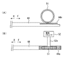
図5は、制御軸44の駆動機構を示す図である。具体的には、図5(A)は駆動機構を示す側面図であり、図5(B)はその平面図である。図5に示すように、制御軸44の端部には、ラックギヤ44aが形成されている。このラックギヤ44aと噛み合わされるようにピニオンギヤ51が配置されている。ピニオンギヤ51は、電動式のアクチュエータ(以下「電動アクチュエータ」という。)52の出力軸52aと固定されている。これにより、電動アクチュエータ52の回転力が与えられた場合に、制御軸44を軸方向に移動させることが可能となる。
FIG. 5 is a view showing a drive mechanism of the
上記の構成によれば、制御軸44が軸方向に移動することで、入力部45と揺動カム46とが互いに逆方向に回転する。これにより、入力部45のローラ45cと、揺動カム46のノーズ46aとの位相差が変化する。よって、ECU60の指令に基づいて電動アクチュエータ52が駆動されることで、制御軸44の軸方向における位置を調整することができ、吸気バルブ14のリフト量及び作用角が可変となる。具体的には、吸気バルブ14のリフト量及び作用角は、制御軸44を方向Fへ移動させるほど大きくなり、制御軸44を方向Rへ移動させるほど小さくなる。
According to the above configuration, when the
[本実施の形態の特徴]
上記システムによれば、可変動弁機構17の制御軸44の位置を制御することで、吸気バルブ14のリフト量及び作用角を小さくすることができる。小リフト量及び小作用角で運転することにより、大きいスロットル開度TAを確保しつつ、燃焼室10内に吸入される空気量を少なくすることができる。よって、ポンピングロスの低減により、燃費を向上させることができる。
[Features of this embodiment]
According to the above system, the lift amount and operating angle of the
ところで、吸気バルブ14にデポジットが付着したり、リフト量の調整不良が発生したりすると、気筒間でリフト量及び作用角のばらつきが生じる。その結果、気筒間で吸入空気量のばらつきが生じてしまう。上述したように、小リフト量及び小作用角で運転する場合は吸入空気量が少ないため、吸入空気量が多い場合(すなわち、大リフト及び大作用角で運転する場合)に比して、気筒間のリフト量及び作用角のばらつきの影響が大きい。従って、小リフト量及び小作用角で運転する場合には、かかる気筒間のリフト量及び作用角のばらつきが小さくても、大きなトルク変動が生じたり、空燃比制御性が大幅に低下してエミッション特性が悪化する可能性がある。よって、気筒間のリフト量及び作用角のばらつきを定期的に検出し、ばらつきが許容値よりも大きい場合には補正する必要がある。かかるばらつきは、例えば、気筒毎に求められた吸入空気量や筒内圧等の差に基づいて検出することができる。
By the way, if deposits adhere to the
既述した装置によれば、アイドル運転時に作用角を増加側に補正することで、気筒間の吸入空気量のばらつきが補正されている。しかし、このように作用角を補正すると、小リフト量及び小作用角で運転することができないため、燃費改善効果が不十分になってしまう。 According to the above-described device, the variation in intake air amount between the cylinders is corrected by correcting the operating angle to the increasing side during the idling operation. However, if the operating angle is corrected in this way, the vehicle cannot be operated with a small lift amount and a small operating angle, so that the fuel efficiency improvement effect becomes insufficient.
ところで、吸入空気量は、吸気圧が一定である条件下では、吸気バルブ14の閉弁時期によって定まる。具体的には、吸気バルブ14の閉弁時期が上死点TDCに近いほど吸入空気量は少なくなり、下死点BDCに近いほど吸入空気量は多くなる。換言すれば、吸気バルブ14の閉弁時のピストン3の位置によって、吸入空気量が定まる。よって、吸気バルブ14の閉弁時のピストン位置のばらつきが小さいほど、気筒間の吸入空気量のばらつきも小さくなる。
Incidentally, the intake air amount is determined by the closing timing of the
そこで、本実施の形態では、図6に示すように、吸気バルブ14の目標閉弁時期を下死点BDC付近に設定する。図6は、本実施の形態において、吸気バルブ14の閉弁時におけるピストン位置のばらつきを示す図である。図6には、作用角が制御目標値よりも小さい側にずれることで吸気バルブ14の閉弁時期が目標閉弁時期よりも進角側にずれている気筒と、作用角が目標値よりも大きい側にずれることで吸気バルブ14の閉弁時期よりも遅角側にずれている気筒とが示されている。かかる2つの気筒間でリフト量及び作用角がばらついているため、吸気バルブ14の閉弁時期は角度Aだけ異なっている。上述したように吸気バルブ14の目標閉弁時期を下死点付近に設定することにより、気筒間で作用角のばらつきが発生しているときでも、吸気バルブ14の閉弁時のピストン位置のばらつきが小さくされる。その結果、気筒間の吸入空気量のばらつきを十分に抑制することができる。さらに、リフト量及び作用角は小さく保たれているため、十分な燃費向上効果を確保することができる。
Therefore, in the present embodiment, as shown in FIG. 6, the target valve closing timing of the
図7は、本実施の形態において、吸気バルブ14の目標閉弁時期の設定例を説明するための図である。図7において、作用角が目標値どおりに制御される気筒を「作用角ずれ無し」と示している。また、作用角が目標値よりも大きい側にずれることで、吸気バルブ14の閉弁時期が制御目標よりも遅角側にずれる気筒を「作用角大」と示している。さらに、作用角が目標値よりも小さい側にずれることで、吸気バルブ14の閉弁時期が制御目標よりも進角側にずれる気筒を「作用角小」と示している。
FIG. 7 is a diagram for explaining a setting example of the target valve closing timing of the
図7(A)に示す例では、「作用角ずれ無し」気筒と、「作用角大」気筒とが存在している。ここで、「作用角ずれ無し」気筒の吸気弁閉弁時期が最進角側であり、「作用角大」気筒の吸気弁閉弁時期が最遅角側である。この場合、最進角側の吸気弁閉弁時期と最遅角側の吸気弁閉弁時期との平均値が下死点BDCとなるように、吸気バルブ14の目標閉弁時期が設定される。具体的には、該目標閉弁時期は下死点BDCよりも進角側のB点に設定される。これにより、吸気バルブ閉弁時における「作用角ずれ無し」気筒のピストン位置と、「作用角大」気筒のピストン位置とを同等にすることができる。
In the example shown in FIG. 7A, there are “no working angle deviation” cylinders and “large working angle” cylinders. Here, the intake valve closing timing of the “no operating angle deviation” cylinder is the most advanced angle side, and the intake valve closing timing of the “large operating angle” cylinder is the most retarded angle side. In this case, the target valve closing timing of the
図7(B)に示す例では、「作用角ずれ無し」気筒と、「作用角小」気筒とが存在している。ここで、「作用角小」気筒の吸気弁閉弁時期が最進角側であり、「作用角ずれ無し」気筒の吸気弁閉弁時期が最遅角側である。この場合も、最進角側の吸気弁閉弁時期と最遅角側の吸気弁閉弁時期との平均値が下死点BDCとなるように、吸気バルブ14の目標閉弁時期が設定される。具体的には、該目標閉弁時期は下死点BDCよりも遅角側のC点に設定される。これにより、吸気バルブ閉弁時における「作用角小」気筒のピストン位置と、「作用角ずれ無し」気筒のピストン位置とを同等にすることができる。
In the example shown in FIG. 7B, there are “no working angle deviation” cylinders and “small working angle” cylinders. Here, the intake valve closing timing of the “small working angle” cylinder is the most advanced angle side, and the intake valve closing timing of the “no working angle deviation” cylinder is the most retarded angle side. Also in this case, the target valve closing timing of the
図7(C)に示す例では、「作用角ずれ無し」気筒と、「作用角小」気筒と、「作用角大」気筒とが存在している。ここで、「作用角小」気筒の吸気弁閉弁時期が最進角側であり、「作用角大」気筒の吸気弁閉弁時期が最遅角側である。この場合も、最進角側の吸気弁閉弁時期と最遅角側の吸気弁閉弁時期との平均値が下死点BDCとなるように、吸気バルブ14の目標閉弁時期が設定される。具体的には、該目標閉弁時期は、下死点BDCに設定される。これにより、吸気バルブ閉弁時におけるピストン位置のばらつきを最小にすることができる。
In the example shown in FIG. 7C, there are a “no working angle deviation” cylinder, a “small working angle” cylinder, and a “large working angle” cylinder. Here, the intake valve closing timing of the “small operating angle” cylinder is the most advanced angle side, and the intake valve closing timing of the “large operating angle” cylinder is the most retarded angle side. Also in this case, the target valve closing timing of the
上述のように、吸気バルブ14の目標閉弁時期を下死点BDC付近に設定することで、リフト量及び作用角を増加側に補正することなく、つまり、小リフト量及び小作用角のままで、気筒間の吸入空気量のばらつきを抑制される。
このように、気筒間の吸入空気量のばらつきを抑制すべく、小作用角及び小リフト量に保ったまま、吸気バルブ14の目標閉弁時期を下死点BDC付近に設定すると、図8に実線L1で示される吸気バルブ14の開弁期間となる。すなわち、吸気バルブ14は遅開きの設定となる。図8は、気筒間の吸入空気量のばらつき抑制時において、吸気バルブ14及び排気バルブ33の開弁期間を示す図である。図8には、通常の排気バルブ33の開弁期間を破線L2で示している。この破線L2で示される排気バルブ33の開弁期間と、実線L1で示される吸気バルブ14の開弁期間との間には、吸気バルブ14と排気バルブ33の両方が閉じられた期間が存在する。この両方のバルブ14,33が閉じられた期間は、ポンプ損失を増大させるため、燃費ロスが生じてしまう。
そこで、本実施の形態では、図8に実線L3で示すように、排気バルブ33の閉弁時期が、吸気バルブ14の開弁時期と同じか、もしくは、遅角側になるように、排気バルブ33の位相(閉弁時期)を遅角させる。これにより、吸気バルブ14の閉弁時期を下死点付近に設定することに起因するポンプ損失の発生を抑制することができるため、燃費ロスを抑制することができる。
As described above, by setting the target valve closing timing of the
As described above, when the target valve closing timing of the
Therefore, in the present embodiment, as indicated by the solid line L3 in FIG. 8, the
[実施の形態における具体的処理]
図9は、本実施の形態において、ECU60が実行するルーチンを示すフローチャートである。
図9に示すルーチンでは、先ず、内燃機関1の運転状態を取得する(ステップ100)。このステップ100では、機関回転数NE、負荷KL、吸気圧、筒内圧等がECU60内に読み込まれる。
[Specific processing in the embodiment]
FIG. 9 is a flowchart showing a routine executed by the
In the routine shown in FIG. 9, first, the operating state of the
次に、気筒間のリフト量及び作用角のばらつきの検出要求が有るか否かを判別する(ステップ102)。このステップ102では、前回のばらつき検出時から所定の距離だけ走行したか否かが判別される。ここで、ECU60は、本ルーチンとは別のルーチンにおいて、前回のばらつき検出時からの走行距離数をカウントしている。このステップ102では、カウントされた走行距離数が読み込まれ、読み込まれた走行距離数が基準値よりも大きい場合に、ばらつき検出要求が有ると判断される。
Next, it is determined whether or not there is a request for detecting variations in lift amount and operating angle between cylinders (step 102). In this
上記ステップ102でばらつき検出要求が無いと判別された場合、つまり、走行距離数が基準値以下である場合には、本ルーチンを一旦終了する。一方、ステップ102でばらつき検出要求が有ると判別された場合には、ばらつき検出の前提条件を具備しているか否かを判別する(ステップ104)。このステップ104では、例えば、小リフト量/小作用角で運転中であり、機関回転数NEが所定値以下(すなわち、低回転)であり、かつ、定常運転中であるか否かが判別される。ここで、低回転を前提条件とするのは、機関回転数NEが高くなるほど爆発間隔が短くなり、気筒毎の吸入空気量や筒内圧等が検出し難くなるためである。
If it is determined in
上記ステップ104で前提条件を具備していないと判別された場合には、本ルーチンを一旦終了する。一方、ステップで前提条件を具備していると判別された場合には、気筒間のリフト量及び作用角のばらつきを検出する(ステップ106)。このステップ106では、先ず、気筒毎の吸入空気量が求められる。そして、ECU60内に予め記憶されたマップを参照して、この求められた吸入空気量に応じたリフト量及び作用角が気筒毎に算出される。そうすると、気筒間のリフト量及び作用角のばらつきを検出することができる。なお、吸入空気量以外にも、気筒毎の機関回転数、吸気圧、筒内圧又は排気空燃比を求め、それらの差分に基づいて、ばらつきを検出することができる。
If it is determined in step 104 that the preconditions are not satisfied, this routine is temporarily terminated. On the other hand, if it is determined in step that the preconditions are satisfied, variations in lift amount and operating angle between cylinders are detected (step 106). In this
次に、上記ステップ106で検出されたばらつきが、基準値(許容値)よりも大きいか否かを判別する(ステップ108)。このステップ108でばらつきが基準値以下であると判別された場合には、気筒間の吸入空気量のばらつきの抑制が不要であると判断され、本ルーチンを一旦終了する。
一方、上記ステップ108でばらつきが基準値よりも大きいと判別された場合には、気筒間の吸入空気量のばらつきを抑制する必要があると判断される。この場合、全気筒の吸気バルブ14の閉弁時期を算出する(ステップ110)。このステップ110では、上記ステップ106で求められた各気筒の吸気バルブ14のリフト量及び作用角に基づき、吸気バルブ14の閉弁時期が算出される。
Next, it is determined whether or not the variation detected in
On the other hand, if it is determined in
次に、上記ステップ110で算出された全気筒の吸気バルブ14の閉弁時期のうちで、最も進角側の閉弁時期と、最も遅角側の閉弁時期との平均値を算出する(ステップ112)。図7(C)に示す例では、「作用角小」の閉弁時期と、「作用角大」の閉弁時期との平均値が算出される。
そして、この平均値が下死点BDCとなるように、吸気バルブ14の目標閉弁時期を設定する(ステップ114)。すなわち、かかる目標閉弁時期となるように、第2可変動弁機構18により吸気バルブ14の位相が変更される。
Next, among the closing timings of the
Then, the target valve closing timing of the
次に、第3可変動弁機構36により排気バルブ33の位相を制御することで、排気バルブ33の閉弁時期を吸気バルブ14の開弁時期と同じかそれよりも遅角側に設定する(ステップ116)。図8に示す例では、排気バルブ33の閉弁時期が、吸気バルブ14の開弁時期よりも遅角側に設定されている。これにより、吸気バルブ14と排気バルブ33が共に開弁しているバルブオーバーラップ期間が確保される。
Next, by controlling the phase of the
以上説明したように、図9に示すルーチンによれば、気筒間のリフト量及び作用角のばらつきが基準値よりも大きい場合には、最進角側の吸気バルブ14の閉弁時期と、最遅角側の吸気バルブ14の閉弁時期との平均値が下死点BDCとなるように、吸気バルブ14の目標閉弁時期が設定される。これにより、吸気バルブ14の閉弁時における、ピストン位置のばらつきを最小にすることができる。よって、気筒間の吸入空気量のばらつきを十分に抑制することができる。ここで、吸気バルブ14のリフト量及び作用角は増加側に補正されないため、小リフト及び小作用角で運転することによる燃費向上効果を十分に得ることができる。従って、燃費向上効果を十分に得つつ、気筒間の吸入空気量のばらつきを十分に抑制することができる。
さらに、排気バルブ33の閉弁時期を吸気バルブ14の開弁時期と同じかそれよりも遅角側に設定することで、ポンピング損失による燃費ロスの発生を抑制することができる。
As described above, according to the routine shown in FIG. 9, when the variation in the lift amount and the operating angle between the cylinders is larger than the reference value, the closing timing of the
Furthermore, by setting the valve closing timing of the
尚、本実施の形態においては、ECU60が、ステップ106の処理を実行することにより第1の発明における「検出手段」が、ステップ114の処理を実行することにより第1及び第2の発明における「制御手段」が、ステップ110の処理を実行することにより第2の発明における「吸気バルブ閉弁時期算出手段」が、ステップ112の処理を実行することにより第2の発明における「平均値算出手段」が、ステップ116の処理を実行することにより第3の発明における「排気バルブ閉弁時期設定手段」が、それぞれ実現されている。
In the present embodiment, the
1 内燃機関
2 気筒
3 ピストン
6 クランク角センサ
10 燃焼室
11 点火プラグ
12 筒内圧センサ
13 吸気ポート
14 吸気バルブ
15 吸気カム軸
16 吸気カム
17 第1可変動弁機構
18 第2可変動弁機構
20 吸気通路
25 吸気圧センサ
26 スロットルバルブ
28 スロットル開度センサ
29 エアフロメータ
31 アクセル開度センサ
32 排気ポート
33 排気バルブ
34 排気カム軸
35 排気カム
36 第3可変動弁機構
40 空燃比センサ
44 制御軸
45 入力部
46 揺動カム
52,53,54 アクチュエータ
60 ECU
DESCRIPTION OF
Claims (3)
気筒毎に設けられた吸気バルブと、
前記吸気バルブのリフト量及び作用角を変更可能な第1可変動弁機構と、
前記吸気バルブの閉弁時期を変更可能な第2可変動弁機構と、
前記第1可変動弁機構によりリフト量及び作用角が小リフト量及び小作用角にされた状態で、気筒間のリフト量及び作用角のばらつきを検出する検出手段と、
前記検出手段により検出されたばらつきが所定値よりも大きい場合に、前記第1可変動弁機構によりリフト量及び作用角を小リフト量及び小作用角に保ったまま前記第2可変動弁機構により前記吸気バルブの目標閉弁時期を下死点付近に設定する制御手段と、
を備えたことを特徴とする内燃機関の制御装置。 A control device for an internal combustion engine that suppresses variations in the amount of intake air between cylinders,
An intake valve provided for each cylinder;
A first variable valve mechanism capable of changing a lift amount and a working angle of the intake valve;
A second variable valve mechanism capable of changing a closing timing of the intake valve;
Detecting means for detecting variations in lift amount and operating angle between cylinders in a state in which the lift amount and operating angle are set to a small lift amount and a small operating angle by the first variable valve mechanism;
When the variation detected by the detecting means is larger than a predetermined value, the second variable valve mechanism keeps the lift amount and working angle at the small lift amount and small working angle by the first variable valve mechanism. Control means for setting the target valve closing timing of the intake valve near the bottom dead center;
A control apparatus for an internal combustion engine, comprising:
前記制御手段は、
前記検出手段により検出されたばらつきが所定値よりも大きい場合に、全気筒の前記吸気バルブの閉弁時期を算出する吸気バルブ閉弁時期算出手段と、
前記検出手段により検出されたばらつきが所定値よりも大きい場合に、前記吸気バルブ閉弁時期算出手段により算出された閉弁時期のうちの最進角側の閉弁時期と、最遅角側の閉弁時期との平均値を算出する平均値算出手段と、
を含み、前記検出手段により検出されたばらつきが所定値よりも大きい場合に、前記平均値算出手段により算出された平均値が下死点となるように、前記吸気バルブの目標閉弁時期を設定することを特徴とする内燃機関の制御装置。 The control apparatus for an internal combustion engine according to claim 1,
The control means includes
An intake valve closing timing calculating means for calculating the closing timing of the intake valves of all cylinders when the variation detected by the detecting means is greater than a predetermined value ;
When the variation detected by the detection means is larger than a predetermined value, the most advanced valve closing timing and the most retarded valve closing timing calculated by the intake valve closing timing calculating means An average value calculating means for calculating an average value with the valve closing timing;
And the target valve closing timing of the intake valve is set so that the average value calculated by the average value calculation means becomes the bottom dead center when the variation detected by the detection means is larger than a predetermined value. A control device for an internal combustion engine.
気筒毎に設けられた排気バルブと、
前記排気バルブの閉弁時期を変更可能な第3可変動弁機構と、
前記検出手段により検出されたばらつきが所定値よりも大きい場合に、前記第3可変動弁機構により前記排気バルブの閉弁時期を前記吸気バルブの開弁時期と同じかそれよりも遅角側に設定する排気バルブ閉弁時期設定手段と、
を備えたことを特徴とする内燃機関の制御装置。 The control device for an internal combustion engine according to claim 1 or 2,
An exhaust valve provided for each cylinder;
A third variable valve mechanism capable of changing a closing timing of the exhaust valve;
When the variation detected by the detecting means is larger than a predetermined value , the third variable valve mechanism makes the valve closing timing of the exhaust valve the same as or slower than the valve opening timing of the intake valve. Exhaust valve closing timing setting means to be set;
A control apparatus for an internal combustion engine, comprising:
Priority Applications (1)
| Application Number | Priority Date | Filing Date | Title |
|---|---|---|---|
| JP2006052896A JP4710652B2 (en) | 2006-02-28 | 2006-02-28 | Control device for internal combustion engine |
Applications Claiming Priority (1)
| Application Number | Priority Date | Filing Date | Title |
|---|---|---|---|
| JP2006052896A JP4710652B2 (en) | 2006-02-28 | 2006-02-28 | Control device for internal combustion engine |
Publications (2)
| Publication Number | Publication Date |
|---|---|
| JP2007231799A JP2007231799A (en) | 2007-09-13 |
| JP4710652B2 true JP4710652B2 (en) | 2011-06-29 |
Family
ID=38552650
Family Applications (1)
| Application Number | Title | Priority Date | Filing Date |
|---|---|---|---|
| JP2006052896A Expired - Fee Related JP4710652B2 (en) | 2006-02-28 | 2006-02-28 | Control device for internal combustion engine |
Country Status (1)
| Country | Link |
|---|---|
| JP (1) | JP4710652B2 (en) |
Families Citing this family (1)
| Publication number | Priority date | Publication date | Assignee | Title |
|---|---|---|---|---|
| US9026338B2 (en) | 2010-03-23 | 2015-05-05 | Toyota Jidosha Kabushiki Kaisha | Control apparatus for internal combustion engine |
Citations (4)
| Publication number | Priority date | Publication date | Assignee | Title |
|---|---|---|---|---|
| JP2003090235A (en) * | 2001-09-18 | 2003-03-28 | Nissan Motor Co Ltd | Variable valve system for internal combustion engine |
| JP2003247443A (en) * | 2002-02-25 | 2003-09-05 | Nissan Motor Co Ltd | Internal combustion engine with variable shift valve mechanism |
| JP2004076641A (en) * | 2002-08-16 | 2004-03-11 | Nissan Motor Co Ltd | Intake control device for internal combustion engine |
| JP2004197630A (en) * | 2002-12-18 | 2004-07-15 | Toyota Motor Corp | Controller of internal combustion engine |
-
2006
- 2006-02-28 JP JP2006052896A patent/JP4710652B2/en not_active Expired - Fee Related
Patent Citations (4)
| Publication number | Priority date | Publication date | Assignee | Title |
|---|---|---|---|---|
| JP2003090235A (en) * | 2001-09-18 | 2003-03-28 | Nissan Motor Co Ltd | Variable valve system for internal combustion engine |
| JP2003247443A (en) * | 2002-02-25 | 2003-09-05 | Nissan Motor Co Ltd | Internal combustion engine with variable shift valve mechanism |
| JP2004076641A (en) * | 2002-08-16 | 2004-03-11 | Nissan Motor Co Ltd | Intake control device for internal combustion engine |
| JP2004197630A (en) * | 2002-12-18 | 2004-07-15 | Toyota Motor Corp | Controller of internal combustion engine |
Also Published As
| Publication number | Publication date |
|---|---|
| JP2007231799A (en) | 2007-09-13 |
Similar Documents
| Publication | Publication Date | Title |
|---|---|---|
| US7314041B2 (en) | EGR control system for internal combustion engine | |
| US7451754B2 (en) | Control system for internal combustion engine | |
| US7869929B2 (en) | Internal combustion engine having variable valve lift mechanism | |
| JP4525517B2 (en) | Internal combustion engine | |
| JP4297082B2 (en) | Air-fuel ratio control device for internal combustion engine | |
| JP4905591B2 (en) | High expansion ratio internal combustion engine | |
| JP2008019756A (en) | Variable valve gear of internal combustion engine | |
| EP2851539B1 (en) | Control device and control method for internal combustion engine | |
| JP2007231798A (en) | Control device for internal combustion engine | |
| US7753016B2 (en) | Control apparatus for internal combustion engine | |
| JP4802717B2 (en) | Valve characteristic control device for internal combustion engine | |
| JP4710652B2 (en) | Control device for internal combustion engine | |
| JP2007113513A (en) | Control device for multiple cylinder internal combustion engine | |
| JP4415864B2 (en) | Control device for internal combustion engine | |
| JP4258453B2 (en) | Intake control device for internal combustion engine | |
| JP5092956B2 (en) | Method for controlling internal combustion engine for vehicle and internal combustion engine system | |
| JP5157672B2 (en) | Multi-cylinder engine air-fuel ratio control method | |
| JP5049926B2 (en) | Exhaust gas recirculation control method for internal combustion engine | |
| JP5169682B2 (en) | Method for controlling internal combustion engine and internal combustion engine system | |
| JP4807314B2 (en) | Diesel engine | |
| JP4382023B2 (en) | EGR control device for internal combustion engine | |
| JP4618039B2 (en) | Internal combustion engine system | |
| JP2009127485A (en) | Internal combustion engine | |
| JP5136332B2 (en) | Method for controlling internal combustion engine and internal combustion engine system | |
| JP4661646B2 (en) | Control device for internal combustion engine |
Legal Events
| Date | Code | Title | Description |
|---|---|---|---|
| A621 | Written request for application examination |
Free format text: JAPANESE INTERMEDIATE CODE: A621 Effective date: 20080801 |
|
| A977 | Report on retrieval |
Free format text: JAPANESE INTERMEDIATE CODE: A971007 Effective date: 20091228 |
|
| A131 | Notification of reasons for refusal |
Free format text: JAPANESE INTERMEDIATE CODE: A131 Effective date: 20100105 |
|
| A521 | Written amendment |
Free format text: JAPANESE INTERMEDIATE CODE: A523 Effective date: 20100302 |
|
| A131 | Notification of reasons for refusal |
Free format text: JAPANESE INTERMEDIATE CODE: A131 Effective date: 20100921 |
|
| A521 | Written amendment |
Free format text: JAPANESE INTERMEDIATE CODE: A523 Effective date: 20101001 |
|
| A01 | Written decision to grant a patent or to grant a registration (utility model) |
Free format text: JAPANESE INTERMEDIATE CODE: A01 Effective date: 20110222 |
|
| A61 | First payment of annual fees (during grant procedure) |
Free format text: JAPANESE INTERMEDIATE CODE: A61 Effective date: 20110307 |
|
| FPAY | Renewal fee payment (event date is renewal date of database) |
Free format text: PAYMENT UNTIL: 20140401 Year of fee payment: 3 |
|
| LAPS | Cancellation because of no payment of annual fees |