JP4525517B2 - Internal combustion engine - Google Patents
Internal combustion engine Download PDFInfo
- Publication number
- JP4525517B2 JP4525517B2 JP2005229609A JP2005229609A JP4525517B2 JP 4525517 B2 JP4525517 B2 JP 4525517B2 JP 2005229609 A JP2005229609 A JP 2005229609A JP 2005229609 A JP2005229609 A JP 2005229609A JP 4525517 B2 JP4525517 B2 JP 4525517B2
- Authority
- JP
- Japan
- Prior art keywords
- internal combustion
- bank
- combustion engine
- phase angle
- engine
- Prior art date
- Legal status (The legal status is an assumption and is not a legal conclusion. Google has not performed a legal analysis and makes no representation as to the accuracy of the status listed.)
- Expired - Fee Related
Links
- 238000002485 combustion reaction Methods 0.000 title claims description 129
- 210000000056 organ Anatomy 0.000 claims 2
- 239000000446 fuel Substances 0.000 description 60
- 238000000034 method Methods 0.000 description 38
- 230000008569 process Effects 0.000 description 38
- 230000007246 mechanism Effects 0.000 description 25
- 230000006835 compression Effects 0.000 description 13
- 238000007906 compression Methods 0.000 description 13
- 238000005086 pumping Methods 0.000 description 9
- 230000005856 abnormality Effects 0.000 description 8
- 230000003111 delayed effect Effects 0.000 description 8
- 238000002474 experimental method Methods 0.000 description 8
- 239000003054 catalyst Substances 0.000 description 7
- 239000003921 oil Substances 0.000 description 7
- 230000006872 improvement Effects 0.000 description 6
- 238000002347 injection Methods 0.000 description 6
- 239000007924 injection Substances 0.000 description 6
- 230000008859 change Effects 0.000 description 5
- 239000000498 cooling water Substances 0.000 description 5
- 230000007423 decrease Effects 0.000 description 4
- XLYOFNOQVPJJNP-UHFFFAOYSA-N water Substances O XLYOFNOQVPJJNP-UHFFFAOYSA-N 0.000 description 4
- 238000010586 diagram Methods 0.000 description 3
- 230000006870 function Effects 0.000 description 3
- 230000033001 locomotion Effects 0.000 description 3
- 239000000203 mixture Substances 0.000 description 3
- 206010044048 Tooth missing Diseases 0.000 description 2
- 230000004913 activation Effects 0.000 description 2
- 239000002826 coolant Substances 0.000 description 2
- 230000009849 deactivation Effects 0.000 description 2
- 239000010720 hydraulic oil Substances 0.000 description 2
- 238000010792 warming Methods 0.000 description 2
- 238000000889 atomisation Methods 0.000 description 1
- 230000005540 biological transmission Effects 0.000 description 1
- 230000003197 catalytic effect Effects 0.000 description 1
- 230000001934 delay Effects 0.000 description 1
- 238000001514 detection method Methods 0.000 description 1
- 230000002542 deteriorative effect Effects 0.000 description 1
- 238000006073 displacement reaction Methods 0.000 description 1
- 238000004880 explosion Methods 0.000 description 1
- 230000004048 modification Effects 0.000 description 1
- 238000012986 modification Methods 0.000 description 1
- 230000009467 reduction Effects 0.000 description 1
- 230000004044 response Effects 0.000 description 1
- 230000000979 retarding effect Effects 0.000 description 1
- 230000000630 rising effect Effects 0.000 description 1
- 230000001360 synchronised effect Effects 0.000 description 1
Images


Classifications
-
- F—MECHANICAL ENGINEERING; LIGHTING; HEATING; WEAPONS; BLASTING
- F02—COMBUSTION ENGINES; HOT-GAS OR COMBUSTION-PRODUCT ENGINE PLANTS
- F02D—CONTROLLING COMBUSTION ENGINES
- F02D41/00—Electrical control of supply of combustible mixture or its constituents
- F02D41/0002—Controlling intake air
-
- F—MECHANICAL ENGINEERING; LIGHTING; HEATING; WEAPONS; BLASTING
- F02—COMBUSTION ENGINES; HOT-GAS OR COMBUSTION-PRODUCT ENGINE PLANTS
- F02D—CONTROLLING COMBUSTION ENGINES
- F02D41/00—Electrical control of supply of combustible mixture or its constituents
- F02D41/02—Circuit arrangements for generating control signals
- F02D41/04—Introducing corrections for particular operating conditions
- F02D41/06—Introducing corrections for particular operating conditions for engine starting or warming up
-
- F—MECHANICAL ENGINEERING; LIGHTING; HEATING; WEAPONS; BLASTING
- F01—MACHINES OR ENGINES IN GENERAL; ENGINE PLANTS IN GENERAL; STEAM ENGINES
- F01L—CYCLICALLY OPERATING VALVES FOR MACHINES OR ENGINES
- F01L1/00—Valve-gear or valve arrangements, e.g. lift-valve gear
- F01L1/02—Valve drive
- F01L1/04—Valve drive by means of cams, camshafts, cam discs, eccentrics or the like
- F01L1/047—Camshafts
- F01L1/053—Camshafts overhead type
-
- F—MECHANICAL ENGINEERING; LIGHTING; HEATING; WEAPONS; BLASTING
- F01—MACHINES OR ENGINES IN GENERAL; ENGINE PLANTS IN GENERAL; STEAM ENGINES
- F01L—CYCLICALLY OPERATING VALVES FOR MACHINES OR ENGINES
- F01L1/00—Valve-gear or valve arrangements, e.g. lift-valve gear
- F01L1/34—Valve-gear or valve arrangements, e.g. lift-valve gear characterised by the provision of means for changing the timing of the valves without changing the duration of opening and without affecting the magnitude of the valve lift
-
- F—MECHANICAL ENGINEERING; LIGHTING; HEATING; WEAPONS; BLASTING
- F01—MACHINES OR ENGINES IN GENERAL; ENGINE PLANTS IN GENERAL; STEAM ENGINES
- F01L—CYCLICALLY OPERATING VALVES FOR MACHINES OR ENGINES
- F01L13/00—Modifications of valve-gear to facilitate reversing, braking, starting, changing compression ratio, or other specific operations
-
- F—MECHANICAL ENGINEERING; LIGHTING; HEATING; WEAPONS; BLASTING
- F02—COMBUSTION ENGINES; HOT-GAS OR COMBUSTION-PRODUCT ENGINE PLANTS
- F02D—CONTROLLING COMBUSTION ENGINES
- F02D13/00—Controlling the engine output power by varying inlet or exhaust valve operating characteristics, e.g. timing
- F02D13/02—Controlling the engine output power by varying inlet or exhaust valve operating characteristics, e.g. timing during engine operation
- F02D13/0223—Variable control of the intake valves only
- F02D13/0234—Variable control of the intake valves only changing the valve timing only
- F02D13/0238—Variable control of the intake valves only changing the valve timing only by shifting the phase, i.e. the opening periods of the valves are constant
-
- F—MECHANICAL ENGINEERING; LIGHTING; HEATING; WEAPONS; BLASTING
- F02—COMBUSTION ENGINES; HOT-GAS OR COMBUSTION-PRODUCT ENGINE PLANTS
- F02D—CONTROLLING COMBUSTION ENGINES
- F02D13/00—Controlling the engine output power by varying inlet or exhaust valve operating characteristics, e.g. timing
- F02D13/02—Controlling the engine output power by varying inlet or exhaust valve operating characteristics, e.g. timing during engine operation
- F02D13/0261—Controlling the valve overlap
-
- F—MECHANICAL ENGINEERING; LIGHTING; HEATING; WEAPONS; BLASTING
- F02—COMBUSTION ENGINES; HOT-GAS OR COMBUSTION-PRODUCT ENGINE PLANTS
- F02D—CONTROLLING COMBUSTION ENGINES
- F02D41/00—Electrical control of supply of combustible mixture or its constituents
- F02D41/008—Controlling each cylinder individually
- F02D41/0082—Controlling each cylinder individually per groups or banks
-
- F—MECHANICAL ENGINEERING; LIGHTING; HEATING; WEAPONS; BLASTING
- F02—COMBUSTION ENGINES; HOT-GAS OR COMBUSTION-PRODUCT ENGINE PLANTS
- F02D—CONTROLLING COMBUSTION ENGINES
- F02D41/00—Electrical control of supply of combustible mixture or its constituents
- F02D41/02—Circuit arrangements for generating control signals
- F02D41/04—Introducing corrections for particular operating conditions
- F02D41/06—Introducing corrections for particular operating conditions for engine starting or warming up
- F02D41/062—Introducing corrections for particular operating conditions for engine starting or warming up for starting
-
- F—MECHANICAL ENGINEERING; LIGHTING; HEATING; WEAPONS; BLASTING
- F02—COMBUSTION ENGINES; HOT-GAS OR COMBUSTION-PRODUCT ENGINE PLANTS
- F02N—STARTING OF COMBUSTION ENGINES; STARTING AIDS FOR SUCH ENGINES, NOT OTHERWISE PROVIDED FOR
- F02N19/00—Starting aids for combustion engines, not otherwise provided for
- F02N19/004—Aiding engine start by using decompression means or variable valve actuation
-
- F—MECHANICAL ENGINEERING; LIGHTING; HEATING; WEAPONS; BLASTING
- F02—COMBUSTION ENGINES; HOT-GAS OR COMBUSTION-PRODUCT ENGINE PLANTS
- F02B—INTERNAL-COMBUSTION PISTON ENGINES; COMBUSTION ENGINES IN GENERAL
- F02B75/00—Other engines
- F02B75/16—Engines characterised by number of cylinders, e.g. single-cylinder engines
- F02B75/18—Multi-cylinder engines
- F02B75/22—Multi-cylinder engines with cylinders in V, fan, or star arrangement
-
- F—MECHANICAL ENGINEERING; LIGHTING; HEATING; WEAPONS; BLASTING
- F02—COMBUSTION ENGINES; HOT-GAS OR COMBUSTION-PRODUCT ENGINE PLANTS
- F02D—CONTROLLING COMBUSTION ENGINES
- F02D41/00—Electrical control of supply of combustible mixture or its constituents
- F02D41/0002—Controlling intake air
- F02D2041/001—Controlling intake air for engines with variable valve actuation
-
- Y—GENERAL TAGGING OF NEW TECHNOLOGICAL DEVELOPMENTS; GENERAL TAGGING OF CROSS-SECTIONAL TECHNOLOGIES SPANNING OVER SEVERAL SECTIONS OF THE IPC; TECHNICAL SUBJECTS COVERED BY FORMER USPC CROSS-REFERENCE ART COLLECTIONS [XRACs] AND DIGESTS
- Y02—TECHNOLOGIES OR APPLICATIONS FOR MITIGATION OR ADAPTATION AGAINST CLIMATE CHANGE
- Y02T—CLIMATE CHANGE MITIGATION TECHNOLOGIES RELATED TO TRANSPORTATION
- Y02T10/00—Road transport of goods or passengers
- Y02T10/10—Internal combustion engine [ICE] based vehicles
- Y02T10/12—Improving ICE efficiencies
-
- Y—GENERAL TAGGING OF NEW TECHNOLOGICAL DEVELOPMENTS; GENERAL TAGGING OF CROSS-SECTIONAL TECHNOLOGIES SPANNING OVER SEVERAL SECTIONS OF THE IPC; TECHNICAL SUBJECTS COVERED BY FORMER USPC CROSS-REFERENCE ART COLLECTIONS [XRACs] AND DIGESTS
- Y02—TECHNOLOGIES OR APPLICATIONS FOR MITIGATION OR ADAPTATION AGAINST CLIMATE CHANGE
- Y02T—CLIMATE CHANGE MITIGATION TECHNOLOGIES RELATED TO TRANSPORTATION
- Y02T10/00—Road transport of goods or passengers
- Y02T10/10—Internal combustion engine [ICE] based vehicles
- Y02T10/40—Engine management systems
Landscapes
- Engineering & Computer Science (AREA)
- Mechanical Engineering (AREA)
- General Engineering & Computer Science (AREA)
- Chemical & Material Sciences (AREA)
- Combustion & Propulsion (AREA)
- Output Control And Ontrol Of Special Type Engine (AREA)
- Electrical Control Of Air Or Fuel Supplied To Internal-Combustion Engine (AREA)
- Combined Controls Of Internal Combustion Engines (AREA)
- Valve Device For Special Equipments (AREA)
- Valve-Gear Or Valve Arrangements (AREA)
Description
本発明は、内燃機関に関し、特に複数のバンクを有する内燃機関において、バンク毎に最遅角のバルブタイミングが異なる内燃機関に関する。 The present invention relates to an internal combustion engine, and more particularly, to an internal combustion engine having a plurality of banks with different most retarded valve timings for each bank.
従来より、車両に搭載されている内燃機関にバルブタイミング可変機構が設けられている。バルブタイミング可変機構は、たとえば、吸気バルブの開閉タイミングを電子制御による油圧駆動で連続可変制御することにより、低中速のトルク向上、燃費向上およびエミッション性能向上を図るものである。一方、吸気バルブの閉弁時期は、内燃機関の始動時における始動性を優先して設定される。 Conventionally, a valve timing variable mechanism is provided in an internal combustion engine mounted on a vehicle. The variable valve timing mechanism, for example, aims to improve low and medium speed torque, improve fuel efficiency, and improve emission performance by continuously varying the opening and closing timing of the intake valve by hydraulic drive by electronic control. On the other hand, the closing timing of the intake valve is set by giving priority to the startability at the start of the internal combustion engine.
たとえば、特開平6−323168号公報(特許文献1)は、内燃機関の始動時における噴射燃料の微粒化を促進し、エミッションの悪化を招くことなく始動性の向上を図る内燃機関の制御装置を開示する。この内燃機関の制御装置は、ピストンの往復運動をクランクシャフトの回転運動に変換して動力を得る内燃機関に設けられ、クランクシャフトの回転にて駆動されることにより、内燃機関の燃焼室に連通する吸気通路および排気通路をそれぞれ開閉する吸気バルブおよび排気バルブと、吸気バルブおよび排気バルブのうち、少なくとも吸気バルブの開弁時期を調整可能な可変バルブタイミング機構と、吸気通路に設けられ、燃焼室へ燃料を噴射する燃料噴射弁と、内燃機関の始動状態を検出する始動状態検出手段と、始動状態検出手段により内燃機関の始動状態が検出されたときには、排気バルブが閉弁し、かつピストンが上死点に達してから吸気バルブを開弁させるとともに、機関始動後の閉弁時期よりも遅く吸気バルブを閉弁させるべく、可変バルブタイミング機構を駆動制御する第1の制御手段と、始動状態検出手段により内燃機関の始動状態が検出されたときには、可変バルブタイミング機構による吸気バルブの開弁時期にて燃料を噴射させるべく、燃料噴射弁を駆動制御する第2の制御手段とを含む。 For example, Japanese Patent Laid-Open No. 6-323168 (Patent Document 1) discloses a control device for an internal combustion engine that promotes atomization of injected fuel at the start of the internal combustion engine and improves startability without deteriorating emissions. Disclose. This control device for an internal combustion engine is provided in an internal combustion engine that obtains power by converting the reciprocating motion of a piston into the rotational motion of a crankshaft, and communicates with the combustion chamber of the internal combustion engine by being driven by the rotation of the crankshaft. An intake valve and an exhaust valve for opening and closing the intake passage and the exhaust passage, a variable valve timing mechanism capable of adjusting at least the opening timing of the intake valve, and a combustion chamber provided in the intake passage. When the start state of the internal combustion engine is detected by the start state detector, the exhaust valve is closed and the piston is In order to open the intake valve after reaching top dead center, and close the intake valve later than the closing timing after engine startup In order to inject fuel at the opening timing of the intake valve by the variable valve timing mechanism when the start state of the internal combustion engine is detected by the first control means for driving and controlling the variable valve timing mechanism and the start state detecting means, Second control means for driving and controlling the fuel injection valve.
上述した文献に開示された内燃機関の制御装置によると、吸気バルブの閉弁時期を始動後の閉弁時期よりも遅らせるため、ピストンが下死点から上死点へ向けて移動する圧縮行程では、ピストンが受ける圧縮抵抗が低下する。この低下にともない、始動時(クランキング時)のエンジン回転数NEが上昇しやすくなり、始動性が向上する。
しかしながら、特許文献1に開示された内燃機関の制御装置においては、吸気バルブの閉弁時期を遅らせて圧縮抵抗を低下させることで、内燃機関の始動性を向上させているが、燃費向上を優先して、閉弁時期をさらに遅らせる場合、内燃機関の始動が可能な筒内圧を得られないという問題がある。
However, in the control apparatus for an internal combustion engine disclosed in
内燃機関の始動時における吸気バルブの閉弁時期は、内燃機関の始動時に少なくとも始動性を損なわない閉弁時期に設定する必要がある。これは、閉弁時期に応じて点火時期に得られる筒内圧(あるいは圧縮比)が変化するためである。そのため、内燃機関の始動性を優先して閉弁時期を設定する場合には、吸気バルブの閉弁時期の可変範囲は有限であることから、燃費向上を優先して閉弁時期を設定することができない可能性がある。 The closing timing of the intake valve at the start of the internal combustion engine must be set to a closing timing that does not impair the startability at least when the internal combustion engine is started. This is because the in-cylinder pressure (or compression ratio) obtained at the ignition timing changes according to the valve closing timing. Therefore, when setting the valve closing timing with priority on the startability of the internal combustion engine, the variable range of the valve closing timing of the intake valve is finite. May not be possible.
また、燃費向上を優先して閉弁時期を設定する場合には、ポンピングロスを低減させるために閉弁時期がより遅くなるように設定される。そうすると、内燃機関の始動が可能な筒内圧が得られずに始動性が悪化する場合がある。したがって、内燃機関の始動性の確保と燃費の向上との両立が図れないという問題がある。 Further, when the valve closing timing is set with priority on improving fuel efficiency, the valve closing timing is set to be later in order to reduce the pumping loss. As a result, the in-cylinder pressure at which the internal combustion engine can be started cannot be obtained, and the startability may deteriorate. Therefore, there is a problem that it is impossible to achieve both the startability of the internal combustion engine and the improvement of fuel consumption.
本発明は、上述した課題を解決するためになされたものであって、その目的は、始動性の確保および燃費の向上を両立できる内燃機関を提供することである。 The present invention has been made to solve the above-described problems, and an object of the present invention is to provide an internal combustion engine that can ensure both startability and improve fuel efficiency.
第1の発明に係る内燃機関は、複数のバンクを有し、バンクのそれぞれに気筒が設けられる内燃機関である。この内燃機関は、気筒と吸気通路との間に設けられる吸気バルブと、内燃機関の動力により吸気バルブを開閉するカムシャフトと、吸気バルブの閉タイミングに対応するカムシャフトの位相角を内燃機関の作動状態に応じて変更するための変更手段とを含む。変更手段により変更される最も遅角側の最遅位相角がバンクにおいて異なる。 An internal combustion engine according to a first aspect of the present invention is an internal combustion engine having a plurality of banks, each of which is provided with a cylinder. This internal combustion engine has an intake valve provided between a cylinder and an intake passage, a camshaft that opens and closes the intake valve by power of the internal combustion engine, and a phase angle of the camshaft corresponding to the closing timing of the intake valve. Change means for changing according to the operating state. The most retarded phase angle on the most retarded side changed by the changing means is different in the bank.
第1の発明によると、たとえば、内燃機関の始動時のカムシャフトの位相角が最遅位相角であるとする。一方のバンクを始動性を優先した最遅位相角とし、他方のバンクを燃費の向上を優先した最遅位相角とすると、始動時には始動性を優先した方のバンクの気筒を作動させると、良好な始動性を得ることができる。また、内燃機関の作動中に燃費向上を優先した方のバンクの気筒に切り換えると、燃費の向上を図ることができる。すなわち、それぞれのバンクにおいて始動性あるいは燃費向上を優先するように異なる最遅位相角を設定することにより、始動性の確保と燃費向上との両立が図れる。したがって、始動性の確保および燃費向上を両立できる内燃機関を提供することができる。 According to the first invention, for example, it is assumed that the phase angle of the camshaft at the start of the internal combustion engine is the latest phase angle. If one bank is set to the slowest phase angle giving priority to startability and the other bank is set to the slowest phase angle giving priority to improving fuel efficiency, it is good to operate the cylinder of the bank that gives priority to startability when starting. Startability can be obtained. In addition, when the internal combustion engine is operating, switching to the cylinder in the bank that prioritizes improvement in fuel efficiency can improve fuel efficiency. That is, it is possible to ensure both startability and improve fuel efficiency by setting different slowest phase angles so that priority is given to startability or fuel efficiency improvement in each bank. Therefore, it is possible to provide an internal combustion engine that can ensure both startability and improve fuel efficiency.
第2の発明に係る内燃機関においては、第1の発明の構成に加えて、変更手段は、内燃機関の停止時に、最遅位相角になるように位相角を変更するための手段を含む。内燃機関は、始動時において、複数のバンクのうち最遅位相角が遅角側である遅角側バンクと異なる方のバンクの気筒が始動するように制御するための手段をさらに含む。 In the internal combustion engine according to the second aspect of the invention, in addition to the configuration of the first aspect of the invention, the changing means includes means for changing the phase angle so that it becomes the latest phase angle when the internal combustion engine is stopped. The internal combustion engine further includes means for starting the cylinders in a bank different from the retarded-side bank having the most retarded phase angle on the retarded side among the plurality of banks at the time of starting.
第2の発明によると、内燃機関の停止時には、吸気側のカムシャフトの位相角は、最遅位相角に変更される。複数のバンクのうち最遅位相角が遅角側であるバンクと異なる方のバンクの最遅位相角が、始動性を優先して、たとえば、内燃機関の始動が可能な筒内圧が得られる位相角に設定されていると、内燃機関の始動時において、良好な始動性を得ることができる。そして、内燃機関の始動後に、たとえば、最遅位相角が遅角側である方の遅角側バンクの気筒に切り換えると、燃費の向上が図れる。したがって、内燃機関の始動性の確保および燃費向上の両立が図れる。 According to the second invention, when the internal combustion engine is stopped, the phase angle of the intake-side camshaft is changed to the latest phase angle. The phase in which the slowest phase angle of the bank different from the bank having the slowest phase angle on the retard side among the plurality of banks gives priority to startability, for example, an in-cylinder pressure capable of starting the internal combustion engine is obtained. When the angle is set, good startability can be obtained when the internal combustion engine is started. Then, after starting the internal combustion engine, for example, switching to the cylinder in the retard side bank having the most retarded phase angle on the retard side can improve fuel efficiency. Therefore, it is possible to ensure both startability of the internal combustion engine and improve fuel efficiency.
第3の発明に係る内燃機関は、第2の発明の構成に加えて、遅角側バンクと異なる方のバンクの気筒の始動後において、遅角側バンクの気筒が始動するように制御するための手段をさらに含む。 The internal combustion engine according to the third aspect of the invention is controlled so as to start the cylinders in the retarded side bank after starting the cylinders in the bank different from the retarded side bank in addition to the configuration of the second aspect of the invention. These means are further included.
第3の発明によると、遅角側バンクと異なる方のバンクの気筒の始動後において、遅角側バンクの気筒が始動するように制御することにより、内燃機関は全気筒で作動することとなるため、車両に要求される出力を速やかに発生させることができる。 According to the third aspect of the invention, the internal combustion engine operates on all cylinders by controlling so that the cylinders in the retard side bank are started after the cylinders in the bank different from the retard side bank are started. Therefore, the output required for the vehicle can be promptly generated.
第4の発明に係る内燃機関は、第3の発明の構成に加えて、遅角側バンクの気筒の始動後において、遅角側バンクと異なる方のバンクの気筒が休止するように制御するための手段をさらに含む。 In addition to the configuration of the third invention, the internal combustion engine according to the fourth invention is controlled so that the cylinders in the bank different from the retard side bank are deactivated after the cylinders in the retard side bank are started. These means are further included.
第4の発明によると、遅角側バンクの気筒の始動後において、遅角側バンクと異なるバンクの気筒が休止するように制御することにより、遅角側バンクの気筒により内燃機関が作動する。そのため、減筒運転により燃費の向上が図れ、さらに、遅角側バンクにおいて、遅角側バンクと異なる方のバンクよりも吸気バルブの閉弁時期を遅くすることができる。そのため、実圧縮比が低減し、ポンピングロスが低減され、燃費の向上が図れる。 According to the fourth invention, after starting the cylinders in the retard side bank, the internal combustion engine is operated by the cylinders in the retard side bank by controlling so that the cylinders in the bank different from the retard side bank are deactivated. Therefore, the fuel efficiency can be improved by the reduced-cylinder operation, and the closing timing of the intake valve can be delayed in the retard side bank as compared with the bank different from the retard side bank. Therefore, the actual compression ratio is reduced, the pumping loss is reduced, and the fuel consumption can be improved.
第5の発明に係る内燃機関においては、第1〜4のいずれかの発明の構成に加えて、複数のバンクのうち最遅位相角が遅角側である遅角側バンクと異なる方のバンクの最遅位相角は、内燃機関の始動が可能な筒内圧が得られる位相角である。 In the internal combustion engine according to the fifth aspect of the invention, in addition to the structure of any one of the first to fourth aspects, the bank that is different from the retard side bank that has the most retarded phase angle on the retard side among the plurality of banks The latest phase angle is a phase angle at which an in-cylinder pressure capable of starting the internal combustion engine is obtained.
第5の発明によると、遅角側バンクと異なる方のバンクの最遅位相角は、内燃機関の始動が可能な筒内圧が得られる位相角である。したがって、内燃機関の始動時において、遅角側バンクと異なるバンクの気筒を始動させることにより、良好な始動性を得ることができる。 According to the fifth invention, the most retarded phase angle of the bank different from the retarded angle side bank is a phase angle at which an in-cylinder pressure capable of starting the internal combustion engine is obtained. Therefore, when starting the internal combustion engine, good startability can be obtained by starting the cylinders in a bank different from the retard side bank.
第6の発明に係る内燃機関は、第1の発明の構成に加えて、複数のバンクのうち最遅位相角が遅角側である遅角側バンクに設けられ、内燃機関の停止時において、位相角を予め定められた位相角に制限するための制限手段を含む。 The internal combustion engine according to a sixth aspect of the invention is provided in the retard side bank, the most retarded phase angle of which is the retard side, among the plurality of banks, in addition to the configuration of the first invention. Limiting means for limiting the phase angle to a predetermined phase angle is included.
第6の発明によると、制限手段は、複数のバンクのうち、最遅位相角が遅角側である遅角側バンクに設けられ、内燃機関の停止時において、位相角を予め定められた位相角(たとえば、内燃機関の始動が可能な筒内圧が得られる位相角)に制限する。内燃機関の停止時に、遅角側バンクのカムシャフトの位相角を、内燃機関の始動が可能な筒内圧が得られる位相角に制限するようにすると、内燃機関の始動時に、良好な始動性を得ることができる。また、内燃機関の作動中においては、予め定められた位相角からさらに遅角側の位相角に変更するようにすると、始動時よりも吸気バルブの閉弁時期を遅くすることができる。そのため、実圧縮比が低減し、ポンピングロスが低減され、燃費の向上が図れる。 According to the sixth aspect of the invention, limiting means, Chi sac plurality of banks, provided at the retarded angle side bank most retarded phase angle is retarded side, at the time of stop of the internal combustion engine, a defined phase angle advance The phase angle is limited to a phase angle (for example, a phase angle at which a cylinder pressure capable of starting the internal combustion engine is obtained). When the internal combustion engine is stopped, the phase angle of the camshaft of the retard side bank is limited to a phase angle that provides an in-cylinder pressure that can start the internal combustion engine. Obtainable. Further, during the operation of the internal combustion engine, if the phase angle is changed from a predetermined phase angle to a more retarded phase angle, the closing timing of the intake valve can be delayed than at the time of starting. Therefore, the actual compression ratio is reduced, the pumping loss is reduced, and the fuel consumption can be improved.
第7の発明に係る内燃機関においては、第6の発明の構成に加えて、予め定められた位相角は、内燃機関の始動が可能な筒内圧が得られる位相角である。 In the internal combustion engine according to the seventh aspect of the invention, in addition to the configuration of the sixth aspect of the invention, the predetermined phase angle is a phase angle at which an in-cylinder pressure capable of starting the internal combustion engine is obtained.
第7の発明によると、予め定められた位相角は、内燃機関の始動が可能な筒内圧が得られる位相角である。停止時に制限手段により予め定められた位相角に制限されるため、内燃機関の始動時には良好な始動性を得ることができる。また、内燃機関の作動中においては、予め定められた位相角からさらに遅角側の位相角に変更するようにすると、始動時よりも吸気バルブの閉弁時期を遅くすることができる。そのため、実圧縮比が低減し、ポンピングロスが低減され、燃費の向上が図れる。 According to the seventh invention, the predetermined phase angle is a phase angle at which an in-cylinder pressure capable of starting the internal combustion engine is obtained. Since the phase angle is limited to a predetermined phase angle by the limiting means at the time of stop, good startability can be obtained when starting the internal combustion engine. Further, during the operation of the internal combustion engine, if the phase angle is changed from a predetermined phase angle to a more retarded phase angle, the closing timing of the intake valve can be delayed than at the time of starting. Therefore, the actual compression ratio is reduced, the pumping loss is reduced, and the fuel consumption can be improved.
第8の発明に係る内燃機関は、第6または7の発明の構成に加えて、内燃機関の始動後において、遅角側バンクと異なる方のバンクの気筒が休止するように制御するための手段をさらに含む。 In addition to the configuration of the sixth or seventh invention, the internal combustion engine according to the eighth invention is a means for controlling the cylinders in the bank different from the retard side bank to stop after starting the internal combustion engine. Further included.
第8の発明によると、内燃機関の始動後において、遅角側バンクと異なる方のバンクの気筒が休止するように制御する。そのため、減筒運転により燃費の向上が図れ、さらに、遅角側バンクにおいて、遅角側バンクと異なる方のバンクよりも吸気バルブの閉弁時期を遅くすることができる。そのため、実圧縮比が低減し、ポンピングロスが低減され、燃費の向上が図れる。 According to the eighth aspect of the invention, after starting the internal combustion engine, control is performed such that the cylinders in the bank different from the retard side bank are deactivated. Therefore, the fuel efficiency can be improved by the reduced-cylinder operation, and the closing timing of the intake valve can be delayed in the retard side bank as compared with the bank different from the retard side bank. Therefore, the actual compression ratio is reduced, the pumping loss is reduced, and the fuel consumption can be improved.
第9の発明に係る内燃機関は、第6〜8のいずれかの発明の構成に加えて、停止時において、位相角が予め定められた位相角に制限されているか否かを検知するための検知手段と、位相角が予め定められた位相角に制限されていないことが検知されると、内燃機関の始動時において、制限手段が設けられる方のバンクの気筒が休止するように制御するための手段とをさらに含む。 An internal combustion engine according to a ninth invention is, in addition to the configuration of any one of the sixth to eighth inventions, for detecting whether or not the phase angle is limited to a predetermined phase angle when stopped. When the detecting means detects that the phase angle is not limited to a predetermined phase angle, at the time of starting the internal combustion engine, control is performed so that the cylinder of the bank provided with the limiting means is stopped. And means.
第9の発明によると、位相角が予め定められた位相角に制限されていないことが検知されると、内燃機関の始動時において、制限手段が設けられる方のバンクの気筒が休止するように制御する。位相角が予め定められた位相角に制限されていないと、カムシャフトの位相角が、内燃機関の始動が可能な筒内圧が得られる位相角でない可能性が高い。そのため、制限手段が設けられる方のバンクの気筒が休止するように制御して、始動性が確保されている方のバンク(制限手段が設けられるバンクと異なる方のバンク)の気筒で始動することにより、良好な始動性を得ることができる。 According to the ninth aspect of the invention, when it is detected that the phase angle is not limited to the predetermined phase angle, the cylinder of the bank to which the limiting means is provided is stopped when the internal combustion engine is started. Control. If the phase angle is not limited to a predetermined phase angle, there is a high possibility that the phase angle of the camshaft is not a phase angle at which a cylinder pressure capable of starting the internal combustion engine is obtained. Therefore, control is performed so that the cylinder of the bank in which the limiting means is provided is stopped, and the starting is performed in the cylinder in the bank in which startability is ensured (the bank different from the bank in which the limiting means is provided). Thus, good startability can be obtained.
以下、図面を参照しつつ、本発明の実施の形態について説明する。以下の説明では、同一の部品には同一の符号を付してある。それらの名称および機能も同じである。したがってそれらについての詳細な説明は繰返さない。 Hereinafter, embodiments of the present invention will be described with reference to the drawings. In the following description, the same parts are denoted by the same reference numerals. Their names and functions are also the same. Therefore, detailed description thereof will not be repeated.
<第1の実施の形態>
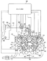
図1に示すように、車両に搭載される内燃機関としてのV型6気筒エンジン300は、複数のシリンダが図面を垂直方向に見てV字状に形成されているシリンダブロック350と、シリンダブロック350の上部にそれぞれ連結される左側シリンダヘッド302と、右側シリンダヘッド304とを備え、左側気筒群306と、右側気筒群308とを形成している。以下、これら気筒群をバンクと称する。本実施の形態において、エンジン300は、V型6気筒の直噴ガソリンエンジンであるとして説明するが、特にこれに限定されるものではなく、複数のバンクを有していれば、水平対向エンジン、または、W型エンジンに本発明を適用してもよい。また、6気筒に限定されるものではなく、4気筒であってもよいし、8気筒であってもよい。さらに、筒内直接噴射型(直噴型)ではなく、ポート噴射型のエンジンに本発明を適用してもよい。
<First Embodiment>
As shown in FIG. 1, a V-type six-
吸気通路202の空気取り入れ側には、エアクリーナ200が接続されており、吸気通路202の途中には、アクセルペダル362の操作量に連動して開閉駆動されるスロットルバルブ204が配設されている。アクセルペダル362の操作量は、ペダルポジションセンサ106により検知される。ペダルポジションセンサ106は、アクセルペダル362の操作量を表わす信号をエンジンECU(Electronic Control Unit)100に送信する。
An
アクセルペダル362に連動してスロットルバルブ204が開閉されることにより、吸入空気量が調整される。吸気通路202には、エアフローメータ210および吸気温度センサ208が設けられる。エアフローメータ210は、吸入空気量を表わす信号をエンジンECU100に送信する。吸気温度センサ208は、吸入空気の温度を表わす信号をエンジンECU100に送信する。
The
スロットルバルブ204の近傍には、スロットルバルブ204を開閉するスロットルモータ206と、スロットル開度TAを検出するスロットルポジションセンサ212が設けられる。エンジンECU100は、検知されたスロットル開度TAに基づいて、要求されたスロットル開度になるようにスロットルモータ206の駆動を制御する。さらに、スロットルバルブ204の下流側において、吸気通路202は、分岐して吸気通路354,356に接続する。
In the vicinity of the
エンジン300は、シリンダブロック350の各気筒310,312内を略上下方向に往復移動するピストン314,316を備え、各ピストン314,316の下端部にはクランクシャフト352が連結されており、各ピストン314,316が上下動することによりクランクシャフト352が回転させられる。
The
また、クランクシャフト352の近傍には、クランクポジションセンサ102が設けられる。クランクポジションセンサ102は、クランクシャフト352に連結されている複数の歯部を有するロータ346と、ロータ346に対向して設けられる電磁ピックアップとから構成される。ロータ346の歯部が電磁ピックアップの前方を通過する毎にパルス状のクランク角度信号が発生する。クランクポジションセンサ102は、発生したクランク角度信号をエンジンECU100に送信する。クランクポジションセンサ102からのクランク角度信号の発生数を計測することで、エンジンECU100にてクランクシャフト352の回転速度(エンジン回転数)が算出される。また、ロータ346には、欠歯部を有しており、エンジンECU100は、欠歯部に対応するクランク角度信号を基準として、クランクシャフト352の回転角度を検知する。
A crank
シリンダブロック350および両シリンダヘッド302,304の内壁と、ピストン314,316の頂部によって区画形成された空間は、混合気を燃焼させるための燃焼室330,332として機能し、両シリンダヘッド302,304の頂部には、混合気を点火するための点火プラグ334,336が、燃焼室330,332に突出するように配設されている。
The spaces defined by the inner walls of the
エンジン300のシリンダヘッド302,304の各気筒の頂部には、燃焼室330,332へ燃料を直接供給するためのインジェクタ318,320が配設されている。各インジェクタ318,320は、通電により開弁される電磁弁であり、各インジェクタ318,320には、高圧の燃料ポンプ(図示しない)から圧送される燃料が供給される。インジェクタ318,320は、EDU(Electronic Driver Unit)348に接続される。EDU348は、高圧のインジェクタ318,320を高速に作動させる。EDU348は、エンジンECU100から受信した制御信号に基づいて、インジェクタ318,320を駆動させる。
したがって、エンジン300の作動時には、吸気通路202には、エアクリーナ200によって濾過された空気が取り込まれ、燃焼室330,332に吸入されたときに、各インジェクタ318,320から各燃焼室330,332に向けて燃料が噴射される。この結果、燃焼室330,332内で混合気が生成され、点火プラグ334,336の点火により、燃焼する。そして、燃焼室330,332における燃焼により発生した排ガスは、排気通路400,402に配設された触媒コンバータ404,406を通って、大気中に排出される。
Therefore, when the
また、シリンダブロック350には、冷却水通路を流れる冷却水の温度(冷却水温度)THWを検出するための水温センサ104が配設されている。さらに、両シリンダヘッド302,304は、それぞれ吸気ポート364,366および排気ポート342,344を有している。吸気ポート364,366のそれぞれには吸気通路354,356が接続されている。排気ポート342,344のそれぞれには排気通路400,402が接続されている。また、両シリンダヘッド302,304の吸気ポート364,366と燃焼室330,332との間のそれぞれには、吸気バルブ322,324が設けられる。排気ポート342,344と燃焼室330,332との間のそれぞれには、排気バルブ338,340が設けられる。
The
そして、左側バンク306の各吸気バルブ322の上方には、吸気バルブ322を開閉駆動するための左側吸気側カムシャフト358が設けられる。右側バンク308の各吸気バルブ324の上方には、吸気バルブ324を開閉駆動するための右側吸気側カムシャフト360が設けられる。また、左側バンク306の各排気バルブ338の上方には、排気バルブ338を開閉駆動するための左側排気側カムシャフト(図示せず)が設けられる。右側バンク308の各排気バルブ340の上方には、排気バルブ340を開閉駆動するための右側排気側カムシャフト(図示せず)が設けられる。
A left
さらに、両吸気側カムシャフト358,360には、それぞれ吸気側タイミングプーリ(図示せず)が装着されており、両排気側カムシャフト(図示せず)の一端には、それぞれ排気側タイミングプーリ(図示せず)が装着されている。そして、各タイミングプーリは、タイミングベルト(図示せず)を介して、クランクシャフト352に連結されている。
Furthermore, both intake-
したがって、エンジン300の作動時には、クランクシャフト352からタイミングベルト及び各タイミングプーリを介して各吸気側カムシャフト358,360および各排気側カムシャフトに回転駆動力が伝達され、各吸気側カムシャフト358,360および各排気側カムシャフトが回転することにより、各吸気バルブ322,324、および各排気バルブ338,340が開閉駆動される。これら各バルブ322,324,338,340は、クランクシャフト352の回転およびピストン314,316の上下動に同期して、すなわち、吸気行程、圧縮行程、爆発・膨張行程、および排気行程よりなるエンジン300における一連の4行程に同期して、所定の開閉タイミングで駆動される。
Therefore, during operation of
さらに、両吸気側カムシャフト358,360の近傍には、それぞれカム角センサ108,110が配設されており、各カム角センサ108,110は、両吸気側カムシャフト358,360に連結された磁性体ロータ(図示せず)と電磁ピックアップ(図示せず)とから構成されている。また、磁性体ロータの外周には、複数の歯部が等角度毎に形成され、たとえば、所定気筒の圧縮TDC(Top Dead Center)の前、BTDC(Before Top Dead Center)90°〜30°の間に、吸気側カムシャフト358,360の回転にともなうパルス状のカム角度信号(変位タイミング信号)が検出されるようになっている。各カム角センサ108,110は、検知したカム角度信号をエンジンECU100に送信する。
Further,
また、本実施の形態に係る内燃機関であるエンジン300には、吸気バルブ322,324の開閉タイミングを変更してバルブオーバラップ量の変更を実現するため、左側バンク306、右側バンク308の吸気側タイミングプーリにそれぞれ、油圧により駆動されるバルブタイミング可変機構326,328(以下、バルブタイミング可変機構を「VVT」とも記載する。)が配設されている。このVVT326,328は、クランクシャフト352(吸気側タイミングプーリ)の回転に対する両吸気側カムシャフト358,360の位相角度を変化させることにより、吸気バルブ322,324のバルブタイミングを連続的(無段階)に変更させるための機構である。
In addition, in
そして、両VVT326,328には、それぞれ対応するオイルコントロールバルブ(図示せず)(以下「OCV」と記載する)、オイルポンプ(図示せず)、オイルフィルタ(図示せず)が接続されている。本実施の形態では、OCV、オイルポンプ等によりVVT326,328のアクチュエータが構成されている。
The
両VVT326,328は、たとえば、ベーン式のアクチュエータを有する。ベーン式のVVT326,328は、吸気側カムシャフト358,360に固定されたベーン部(図示せず)と、ベーン部の両側に設けられる油圧室(進角室と遅角室)とから構成される。進角室の油圧が上昇すると、進角室の油圧の上昇に応じて、吸気側カムシャフト358,360が進角方向に回転するようにベーン部が移動する。そして、遅角室の油圧が上昇すると、吸気側カムシャフト358,360を遅角方向に回転するようにベーン部が移動する。
Both
エンジンECU100は、OCVに対してデューティー制御信号を送信する。OCVは、受信したデューティー制御信号に基づいて、進角室の油圧を上昇させたり(遅角室の油圧を低下させたり)、遅角室の油圧を上昇させたり(進角室の油圧を低下させたり)する。これにより、吸気側カムシャフト358,360の位相角が制御される。
両VVT326,328には、エンジン300の停止時に油圧が低下して油圧がかからなくなると、吸気側カムシャフト358,360の位相角を、最も遅角側の位相角(以下、最遅位相角と記載する)に制限するロックピン(図示せず)が設けられる。ロックピンは、エンジン300の始動時に油圧が上昇すると、解除される。
When both the
以上のようなエンジン300が搭載された車両において、本発明は、左右のバンク306,308の吸気側カムシャフト358,360の最遅位相角がバンクにおいて異なる点に特徴を有する。
In the vehicle equipped with the
本実施の形態に係る内燃機関においては、エンジン300の停止時の油圧がかからない状態において、吸気側カムシャフト358,360の位相角はロックピンにより最遅位相角で制限される。したがって、エンジン300の始動時における左右のバンク306,308の吸気側カムシャフト358,360の位相角が異なる。
In the internal combustion engine according to the present embodiment, the phase angle of
本実施の形態においては、エンジンECU100は、エンジン300の始動時において、左右のバンク306,308のうちの最遅位相角が遅角側である方のバンクと異なるバンクの気筒が始動するようにエンジン300を制御する。たとえば、左バンク306に設けられる吸気側カムシャフト358の最遅位相角が右バンク308側よりも遅角側であるとすると、エンジンECU100は、エンジン300の始動時において、左バンク306の気筒を休止した状態で、右バンク308の気筒だけでエンジン300が始動するようにエンジン300を制御する。
In the present embodiment, when
吸気バルブの閉じタイミングと充填効率により得られる筒内圧との関係は、図2に示すように、下死点から遅閉じ側(吸気側カムシャフトの遅角方向)のA(3)の閉じタイミングにおいて、極大値を有する。図2の横軸左側は、吸気バルブの遅閉じ側であり、右側は早閉じ側である。すなわち、エンジン300の始動時において、吸気バルブの閉じタイミングがA(3)である場合には、得られる筒内圧は最大となり、圧縮比が高いため、良好な始動性が得られることとなる。また、エンジン始動時において、エンジン300が始動可能なP(1)以上の筒内圧が得られる閉じタイミングは、A(2)〜A(4)である。したがって、エンジン300の始動時に始動する右バンク308の吸気側カムシャフト360の最遅位相角は、吸気バルブ324の閉じタイミングがA(2)〜A(4)の間になるように設定される。
As shown in FIG. 2, the relationship between the intake valve closing timing and the in-cylinder pressure obtained from the charging efficiency is as follows: A (3) closing timing from the bottom dead center toward the slow closing side (the retarding direction of the intake camshaft) Has a maximum value. The left side of the horizontal axis in FIG. 2 is the late closing side of the intake valve, and the right side is the early closing side. That is, when the
本実施の形態においては、吸気バルブ324の閉じタイミングは、A(1)〜A(4)の間であれば特に限定されるものではないが、たとえば、始動時の始動性のほか、始動後のバルブタイミングの可変範囲に基づく燃費あるいはエミッション等の観点から適合される。 In the present embodiment, the closing timing of intake valve 324 is not particularly limited as long as it is between A (1) to A (4). For example, in addition to startability at the start, It is adapted from the viewpoint of fuel consumption or emission based on the variable range of valve timing.
一方、左バンク306における吸気バルブ322の閉じタイミングは、エンジン300の作動中に始動するため、P(1)以上の筒内圧が得られなくても始動可能である。したがって、左バンク306の吸気バルブ322の閉じタイミングは、燃費の向上を優先して、A(2)よりも遅閉じ側であるA(1)になるように設定される。吸気バルブ322,324の閉じタイミングは、吸気側カムシャフト358,360の位相角に対応し、位相角は、カム角センサ108,110により検知された吸気側カムシャフト358,360の回転角およびクランクポジションセンサ102により検知されたクランクシャフト352の回転角に基づいて算出される。なお、吸気バルブ322の閉じタイミングA(1)は、A(2)より遅閉じ側であれば特に限定されるものではない。
On the other hand, the closing timing of the intake valve 322 in the
また、エンジンECU100は、エンジン300の運転状態が予め定められた始動条件を満足しないと、片方のバンク(以下、片バンクともいう)で始動し、予め定められた始動条件を満足すると、休止したバンクの気筒を始動させて、両方のバンクで運転する(以下、全気筒運転ともいう)ようにエンジン300を制御する。具体的には、本実施の形態において、エンジンECU100は、エンジン300の始動時において、最遅位相角が遅角側であるバンクと異なるバンク(右バンク308)の気筒でエンジン300を始動し、始動後においては、予め定められた始動条件を満足すると、休止したバンク(左バンク306)の気筒を始動させる。なお、「気筒の休止」とは、フューエルカットされた状態である。好ましくは、気筒の休止中においては、吸気バルブおよび排気バルブが両方とも閉じた状態であることが望ましい。このようにすると、ポンピングロスが低減できる。
In addition,
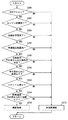
以下、図3を参照して、本実施の形態に係る内燃機関であるエンジン300を制御するエンジンECU100が実行する、エンジン300の始動時に片バンクで始動し、始動後に予め定められた条件を満足すると全気筒運転を行なうプログラムの制御構造について説明する。
Hereinafter, referring to FIG. 3,
ステップ(以下、ステップをSと略す)100にて、エンジンECU100は、エンジン300の始動後であるか否かを判断する。エンジン300の始動後であると(S100にてYES)、処理はS102に移される。もしそうでないと(S100にてNO)、処理はS118に移される。
In step (hereinafter step is abbreviated as S) 100,
S102にて、エンジンECU100は、水温センサ104により検知されたエンジン300の冷却水温が予め定められた温度以上であるか否かを判断する。なお、予め定められた温度は、特に限定されるものではなく、たとえば、実験等により適合される値である。冷却水温が予め定められた温度以上であると(S102にてYES)、処理はS104に移される。もしそうでないと(S102にてNO)、処理はS118に移される。
In S102,
S104にて、エンジンECU100は、油温センサ(図示せず)により検知されたエンジン300の作動油の温度が予め定められた温度以上であるか否かを判断する。なお、予め定められた温度は、特に限定されるものではなく、たとえば、実験等により適合される値である。作動油の温度が予め定められた温度以上であると(S104にてYES)、処理はS106に移される。もしそうでないと(S104にてNO)、処理はS118に移される。
In S104,
S106にて、エンジンECU100は、エンジン300の回転数が予め定められた範囲内であるか否かを判断する。本実施の形態において、エンジン300の回転数は、クランクポジションセンサ102により検知される。また、予め定められた範囲は、特に限定されるものではなく、たとえば、実験等により適合される回転数の範囲である。回転数が予め定められた範囲内であると(S106にてYES)、処理はS108に移される。もしそうでないと(S106にてNO)、処理はS118に移される。
In S106,
S108にて、エンジンECU100は、エンジン300における負荷が予め定められた負荷の範囲内であるか否かを判断する。エンジン300における負荷は、たとえば、ペダルポジションセンサ106により検知されるアクセルペダル362の操作量に基づく、運転者が要求する要求トルクである。なお、エンジン300における負荷は、たとえば、車両のクルーズ走行中に車両に要求される要求トルクであってもよい。予め定められた範囲は、特に限定されるものではなく、たとえば、実験等により適合される範囲である。負荷が予め定められた範囲内であると(S108にてYES)、処理はS110に移される。もしそうでないと(S108にてNO)、処理はS118に移される。
In S108,
S110にて、エンジンECU100は、スロットルが安定しているか否かを判断する。具体的には、エンジンECU100は、スロットルポジションセンサ212により検知されたスロットルバルブ204の開度の変化量が予め定められた変化量以下の略一定状態であるか否かを判断する。スロットルが安定していると判断されると(S110にてYES)、処理はS112に移される。もしそうでないと(S110にてNO)、処理はS118に移される。
In S110,
S112にて、エンジンECU100は、左右のバンク306,308の吸気側カムシャフト358,360の位相角が略同位相であるか否かを判断する。エンジンECU100は、クランクポジションセンサ102により検知されたクランクシャフト352の回転角度およびカム角センサ108,110により検知される吸気側カムシャフト358,360の回転角度に基づいて、吸気側カムシャフト358,360の位相角が略同位相であるか否かを判断する。吸気側カムシャフト358,360の位相角が略同位相であると(S112にてYES)、処理はS114に移される。もしそうでないと(S112にてNO)、処理はS118に移される。
In S112,
S114にて、エンジンECU100は、左バンク306の空燃比センサ112が活性しているか否かを判断する。エンジンECU100は、エンジン300が始動してから、空燃比センサ112の活性に要する時間が経過したか否かに基づいて、空燃比センサ112が活性している否かを判断する。空燃比センサ112が活性していると(S114にてYES)、処理はS116に移される。もしそうでないと(S114にてNO)、処理はS118に移される。
In S114,
S116にて、エンジンECU100は、左右のバンク306,308の全気筒運転を行なうようにエンジン300を制御する。すなわち、エンジンECU100は、左バンク306の気筒が休止していれば、左バンク306の気筒を始動させるように、エンジン300を制御する。すなわち、エンジンECU100は、左バンク306の燃焼室330に燃料が噴射されるようにインジェクタ318を制御する。
In S116,
S118にて、エンジンECU100は、片バンクの気筒だけでエンジン300を作動させる。すなわち、エンジン300の始動時においては、エンジンECU100は、左バンク306の気筒には燃料を供給せず、右バンク308の気筒に燃料を供給するように、インジェクタ318,320を制御して、右バンク308の気筒における燃焼圧だけでエンジン300を始動させる。
In S118,
以上のような構造およびフローチャートに基づく、本実施の形態に係る内燃機関であるエンジン300を制御するエンジンECU100の動作について図4を用いて説明する。
The operation of
エンジン300の始動前の吸気側バルブ322,324の開閉時期は、図4(A)に示すようにそれぞれ最遅角側に制限されている。図4において、「遅閉じ側バンク」が左バンク306であり、「早閉じ側バンク」が右バンク308である。したがって、エンジン300の始動前においては、吸気バルブ322,324とで閉じるタイミングが異なる。
The opening / closing timing of the intake side valves 322 and 324 before the
エンジン300の始動時においては(S100にてNO)、図4(B)に示すように、左右のバンク306,308のうちの最遅位相角が遅角側であるバンクと異なる方のバンク、すなわち、右バンク308の気筒によるエンジン300の始動が行なわれる(S118)。
At the time of starting engine 300 (NO in S100), as shown in FIG. 4B, the bank of the left and
エンジン300の始動後において(S100にてYES)、冷却水温および油温が予め定められた温度以上であって(S102にてYES,S104にてYES)、回転数および負荷が予め定められた範囲内であると(S106にてYES,S108にてYES)、スロットルが安定しているか否かが判断される(S110)。エンジン300の始動後は、エンジンECU100は、吸気側カムシャフト358,360の位相角が略同位相になるように制御する。そのため、スロットルが安定しており(S110にてYES)、図4(C)に示すように、吸気側カムシャフト358,360の位相角が略同位相であって(S112にてYES)、左バンク306側の空燃比センサ112の活性時間が経過していると(S114にてYES)、左右のバンク306,308による全気筒運転が行なわれる(S116)。そして、エンジン300の運転状態が上述のいずれかの条件を満足しないと(S100〜S114のいずれかにてNO)、右バンク308の気筒だけによるエンジン300の運転が継続される(S118)。
After
また、エンジンECU100は、エンジン300の始動後において、全気筒運転(左右のバンク306,308の気筒の燃焼圧による運転)中に、予め定められた休止条件を満足すると、最遅位相角が遅角側のバンクと異なる方のバンク(右バンク308)の気筒を休止させるようにエンジン300を制御する。
Further, after the
以下、図5を参照して、本実施の形態に係る内燃機関であるエンジン300を制御するエンジンECU100が実行する、全気筒運転中に、エンジン300の運転状態が予め定められた休止条件を満足すると減筒制御するプログラムの制御構造について説明する。
Hereinafter, referring to FIG. 5, during the all-cylinder operation, which is executed by
S200にて、エンジンECU100は、シフトポジションが前進走行(D)ポジションであるか否かを判断する。エンジンECU100は、たとえば、ECT(Electronically Controlled Automatic Transmission)_ECU(図示せず)から受信したシフトポジションを表わす信号に基づいて、シフトポジションがDポジションであるか否かを判断する。シフトポジションがDポジションであると(S200にてYES)、処理はS202に移される。もしそうでないと(S200にてNO)、処理はS218に移される。
In S200,
S202にて、エンジンECU100は、エンジン300の暖機が完了したか否かを判断する。エンジンECU100は、たとえば、水温センサ104により検知されるエンジン300の冷却水温が予め定められた温度以上であると、エンジン300の暖機が完了したと判断する。エンジン300の暖機が完了すると(S202にてYES)、処理はS204に移される。もしそうでないと(S202にてNO)、処理はS218に移される。
In S202,
S204にて、エンジンECU100は、空燃比の学習が終了したか否かを判断する。エンジンECU100は、たとえば、空燃比センサ114により検知された空燃比が目標値と略同一であると学習が終了したことを判断する。空燃比の学習が終了すると(S204にてYES)、処理はS206に移される。もしそうでないと(S204にてNO)、処理はS218に移される。
In S204,
S206にて、エンジンECU100は、車速が予め定められた範囲内の速度であるか否かを判断する。エンジンECU100は、たとえば、各車輪に設けられた車輪速センサ(図示せず)から受信した車輪速を表わす信号に基づいて、車速を検知するようにしてもよい。なお、予め定められた範囲は、特に限定されるものではなく、たとえば、実験等により適合される。車速が予め定められた範囲内の速度であると(S206にてYES)、処理はS208に移される。もしそうでないと(S206にてNO)、処理はS218に移される。
In S206,
S208にて、エンジンECU100は、エンジン300の回転数が予め定められた回転数の条件を満足するか否かを判断する。たとえば、エンジンECU100は、エンジン300の回転数が予め定められた範囲内の回転数であるか否かを判断する。なお、予め定められた範囲は、特に限定されるものではなく、たとえば、実験等により適合される。エンジン300の回転数が予め定められた回転数の条件を満足すると(S208にてYES)、処理はS210に移される。もしそうでないと(S208にてNO)、処理はS218に移される。
In S208,
S210にて、エンジンECU100は、エンジン300の負荷が予め定められた範囲内の負荷であるか否かを判断する。なお、予め定められた範囲は、特に限定されるものではなく、たとえば、実験等により適合される。エンジン300の負荷が予め定められた範囲内の負荷であると(S210にてYES)、処理はS212に移される。もしそうでないと(S210にてNO)処理はS218に移される。
In S210,
S212にて、エンジンECU100は、スロットルが安定しているか否かを判断する。スロットルが安定していると(S212にてYES)、処理はS214に移される。もしそうでないと(S212にてNO)、処理はS218に移される。
In S212,
S214にて、エンジンECU100は、触媒温度が予め定められた温度以上である否かを判断する。エンジンECU100は、たとえば、触媒406に設けられた触媒温度センサ(図示せず)により検知された触媒温度が予め定められた温度以上であるか否かを判断する。予め定められた温度は、特に限定されるものではなく、たとえば、実験等により適合される。触媒温度が予め定められた温度以上であると(S214にてYES)、処理はS216に移される。もしそうでないと(S214にてNO)、処理はS218に移される。
In S214,
S216にて、エンジンECU100は、減筒運転するようにエンジン300を制御する。具体的には、エンジンECU100は、左右のバンク306,308のうちの最遅位相角が遅角側である左バンク306と異なる方の右バンク308の気筒が休止するようにエンジン300を制御する。S218にて、エンジンECU100は、全気筒運転するようにエンジン300を制御する。
In S216,
以上のような構造およびフローチャートに基づく、本実施の形態に係る内燃機関であるエンジン300を制御するエンジンECUの動作について図6を用いて説明する。
The operation of engine ECU for controlling
エンジン300の始動後において、シフトポジションがDポジションであると(S200にてYES)、エンジン300の暖機が完了したか否かが判断される(S202)。暖機および空燃比学習が完了しており(S202にてYES,S204にてYES)、車速、エンジン回転数および負荷が予め定められた条件を満足すると(S206にてYES,S208にてYES,S210にてYES)、スロットルが安定している否かが判断される(S212)。スロットルが安定しており(S212にてYES)、触媒温度が予め定められた温度以上であると(S214にてYES)、図6(A)に示すように、右バンク308の気筒を休止して、左バンク306の気筒の燃焼圧でエンジン300の運転を行なう減筒運転を実施する(S216)。そして、上記した条件のうちいずれかを満足しないと(S200〜S216のいずれかにてNO)、図6(B)に示すように、位相角を略同位相角とした全気筒運転を継続する(S218)。
If the shift position is the D position after
以上のようにして、本実施の形態に係る内燃機関によると、右バンクを始動性を優先した最遅位相角とし、左バンクを燃費の向上を優先した最遅位相角とすると、始動時には始動性を優先した右バンクの気筒を作動させると、良好な始動性を得ることができる。また、エンジンの作動中に燃費向上を優先した左バンクの気筒に切り換えると、燃費の向上を図ることができる。すなわち、それぞれのバンクにおいて始動性あるいは燃費向上を優先するように異なる最遅位相角を設定することにより、始動性の確保と燃費向上との両立が図れる。 As described above, according to the internal combustion engine according to the present embodiment, when the right bank is the slowest phase angle that prioritizes startability and the left bank is the slowest phase angle that prioritizes improvement of fuel consumption, the engine is started at the time of start. When the right bank cylinder is operated with priority given to performance, good startability can be obtained. In addition, when the engine is switched to the left bank cylinder that prioritizes the improvement of fuel consumption, the fuel consumption can be improved. That is, it is possible to ensure both startability and improve fuel efficiency by setting different slowest phase angles so that priority is given to startability or fuel efficiency improvement in each bank.
特に、エンジンの停止時には、吸気側のカムシャフトの位相角は、最遅位相角に変更される。そのため、右バンクの最遅位相角が、始動性を優先して、エンジンの始動が可能な筒内圧が得られる位相角に設定されることにより、内燃機関の始動時において、良好な始動性を得ることができる。 In particular, when the engine is stopped, the phase angle of the camshaft on the intake side is changed to the latest phase angle. For this reason, the most retarded phase angle in the right bank is set to a phase angle that gives the in-cylinder pressure at which the engine can be started, giving priority to the startability. Obtainable.
さらに、右バンクのの気筒の始動後において、左バンクの気筒が始動するように制御することにより、エンジンは全気筒で作動することとなるため、車両に要求される出力を速やかに発生させることができる。 Further, after starting the cylinders in the right bank, the engine operates in all cylinders by controlling the cylinders in the left bank to start, so that the output required for the vehicle can be generated quickly. Can do.
また、左バンクの気筒の始動後において、右バンクの気筒が休止するように制御することにより、左バンクの気筒によりエンジンが作動する。そのため、減筒運転により燃費の向上が図れ、さらに、左バンクにおいて、右バンクよりも吸気バルブの閉弁時期を遅くすることができる。そのため、実圧縮比が低減し、ポンピングロスが低減され、燃費の向上が図れる。したがって、始動性の確保および燃費の向上を両立できる内燃機関を提供することができる。 Further, after starting the cylinders in the left bank, the engine is operated by the cylinders in the left bank by controlling so that the cylinders in the right bank are deactivated. Therefore, fuel efficiency can be improved by the reduced-cylinder operation, and the closing timing of the intake valve can be delayed in the left bank than in the right bank. Therefore, the actual compression ratio is reduced, the pumping loss is reduced, and the fuel consumption can be improved. Therefore, it is possible to provide an internal combustion engine that can ensure both startability and improve fuel efficiency.
また、特に直噴型のエンジンにおいては、図7(A)に示すように、吸気バルブの開く期間と排気バルブが開く期間とが重なる期間(いわゆる、オーバーラップの期間)が、上死点よりも前、すなわち、ピストンが上昇している間にあると、吸気ポートに排気ガスが流入し、吸気ポートデポジットが発生する場合がある。一方、図7(B)に示すように、吸気バルブが閉じるタイミングをより遅くすることにより(吸気側カムシャフトの位相角をより遅角側にすることにより)、オーバーラップの期間が、上死点よりも後、すなわち、ピストンが下降し始めるときになるため、吸気ポートへの吹き返しが発生せず、吸気ポートデポジットの発生を抑制することができる。 In particular, in a direct injection type engine, as shown in FIG. 7A, a period in which the intake valve opening period and the exhaust valve opening period overlap (so-called overlap period) from the top dead center. If it is before, i.e., while the piston is rising, exhaust gas may flow into the intake port and an intake port deposit may occur. On the other hand, as shown in FIG. 7B, by making the timing of closing the intake valve later (by making the phase angle of the intake camshaft more retarded), the overlap period is top dead. After the point, that is, when the piston starts to descend, the blowback to the intake port does not occur, and the generation of the intake port deposit can be suppressed.
<第2の実施の形態>
以下、本発明の第2の実施の形態に係る内燃機関について説明する。本実施の形態に係る内燃機関を搭載する車両は、上述の第1の実施の形態に係る内燃機関を搭載する車両の構成と比較して、エンジン300の停止時に、左バンク306の位相角を、右バンク308の最遅位相角と略同じ位相角に制限する中間位相止め機構が設けられる点が異なる。それ以外の構成は、上述の第1の実施の形態に係る内燃機関を搭載する車両の構成と同じ構成である。それらについては同じ参照符号が付してある。それらの機能も同じである。したがって、それらについての詳細な説明はここでは繰り返さない。
<Second Embodiment>
Hereinafter, an internal combustion engine according to a second embodiment of the present invention will be described. The vehicle equipped with the internal combustion engine according to the present embodiment has a phase angle of the
本実施の形態において、中間位相止め機構は、右バンク308よりも最遅位相角が遅角側である左バンク306に設けられる。中間位相止め機構は、たとえば、エンジン300の停止時の油圧がかからない状態において、吸気側カムシャフト358の位相角をロックピンにより予め定められた位相角に制限する。予め定められた位相角は、本実施の形態においては、たとえば、右バンク308の最遅位相角と略同じ位相角である。一方、右バンク308は、エンジン300の停止時に油圧がかからない状態において、吸気側カムシャフト360の位相角は、ロックピンにより、最遅位相角に制限される。したがって、エンジン300の始動時における左右のバンクの吸気側カムシャフト358,360の位相角は略同じ位相角である。
In the present embodiment, the intermediate phase stopping mechanism is provided in the
本実施の形態において、エンジンECU100は、エンジン300の停止時に中間位相止め機構に異常が検知されると、次回の始動時において、中間位相止め機構が設けられる左バンク306の気筒を休止して、右バンク308の気筒の燃焼圧でエンジン300を始動するようにエンジン300を制御する点に特徴を有する。なお、「中間位相止め機構の異常」とは、エンジン300の停止時にロックピンが正常に作動せず、左バンク306の吸気側カムシャフト358の位相角が予め定められた位相角に制限されない状態をいう。
In the present embodiment, when an abnormality is detected in the intermediate phase stopper mechanism when
以下、図8を参照して、本実施の形態に係る内燃機関であるエンジン300を制御するエンジンECUが、中間位相止め機構の異常を検知すると、右バンク308の気筒だけでエンジン300を始動するプログラムの制御構造について説明する。
Hereinafter, referring to FIG. 8, when the engine ECU that controls
S300にて、エンジンECU100は、エンジン300の停止指示があるか否かを判断する。エンジンECU100は、たとえば、運転者によりIGスイッチ(図示せず)のオフが検知されると、エンジンの停止指示があることを判断するようにしてもよい。エンジン300の停止指示があると(S300にてYES)、処理はS304に移される。もしそうでないと(S300にてNO)、処理はS302に移される。
In S300,
S302にて、エンジンECU100は、エンジン300の回転数が予め定められた回転数以下であるか否かを判断する。エンジンECU100は、クランクポジションセンサ102により検知される検知信号に基づいて、エンジン300の回転数を検知する。「予め定められた回転数」は、エンジン300が停止モードになる回転数(いわゆる、エンスト(エンジンストップ)する回転数)である。エンジン300の回転数が予め定められた回転数以下であると(S302にてYES)、処理はS304に移される。もしそうでないと(S302にてNO)、処理はS300に戻される。
In S302,
S304にて、エンジンECU100は、カム角ポジションセンサ108により左バンク306のカム角を検知する。S306にて、エンジンECU100は、中間位相止め機構に異常があるか否かを判断する。具体的には、エンジンECU100は、クランクポジションセンサ102により検知されたクランクシャフト352の回転角およびカム角ポジションセンサ108により検知された吸気側カムシャフト358の回転角に基づいて、吸気側カムシャフト358の位相角が中間位相止め機構により適切な位相角に制限されていないと、中間位相止め機構に異常があると判断する。中間位相止め機構に異常があると(S306にてYES)、処理はS308に移される。もしそうでないと(S306にてNO)、処理はS310に移される。
In S304,
S308にて、エンジンECU100は、次回のエンジン300の始動時においては中間位相止め機構が設けられる左バンク306の気筒を休止して、右バンク308の気筒に燃料を供給してエンジン300が始動するようにエンジン300を制御する。S310にて、エンジンECU100は、次回始動時は通常始動時と同様に、左右のバンク306,308の気筒に燃料を供給してエンジン300が始動するようにエンジン300を制御する。
In S308, at the next start of
以上のような構造およびフローチャートに基づく、本実施の形態に係る内燃機関であるエンジン300を制御するエンジンECU100の動作について図9を用いて説明する。
The operation of
運転者によりIGスイッチがオフされるなどして、エンジン300の停止指示があったり(S300にてYES)、エンジン300の回転数が予め定められた回転数以下となって、エンジン300が停止モードになったりすると(S302にてYES)、クランクシャフト352の回転角および吸気側カムシャフト358の回転角に基づいて、図9(A)に示すように、中間位相止め機構が予め定められた位相角に制限されていないことが検知されると(S306にてYES)、次回の始動時においては、図9(B)に示すように、右バンク308の気筒の燃焼圧でエンジン300が始動される(S308)。一方、中間位相止め機構が予め定められた位相角に制限されると(S306にてNO)、次回の始動時は、図9(C)に示すように、通常始動時と同様に、左右のバンク306,308の気筒の燃焼圧によりエンジン300が始動される(S310)。
The
以上のようにして本実施の形態に係る内燃機関によると、内燃機関の停止時に、左バンクの吸気側カムシャフトを、内燃機関の始動が可能な筒内圧が得られる位相角に制限するようにすると、内燃機関の始動時に左右のバンクの気筒による始動が行なわれて、良好な始動性を得ることができる。また、内燃機関の作動中においては、左バンクの吸気側カムシャフトは、右バンクの最遅位相角よりもさらに遅角側の位相角に変更することができるため、吸気バルブを遅閉じにすることができる。そのため、実圧縮比が低減し、その結果、ポンピングロスを低減させることができるため、燃費の向上が図れる。したがって、始動性の確保および燃費の向上を両立できる内燃機関を提供することができる。 As described above, according to the internal combustion engine according to the present embodiment, when the internal combustion engine is stopped, the intake side camshaft of the left bank is limited to a phase angle at which an in-cylinder pressure capable of starting the internal combustion engine is obtained. Then, when the internal combustion engine is started, the left and right bank cylinders are used for starting, and good startability can be obtained. Further, during the operation of the internal combustion engine, the intake side camshaft of the left bank can be changed to a phase angle that is further retarded than the most retarded phase angle of the right bank, so that the intake valve is closed late. be able to. Therefore, the actual compression ratio is reduced, and as a result, the pumping loss can be reduced, so that the fuel consumption can be improved. Therefore, it is possible to provide an internal combustion engine that can ensure both startability and improve fuel efficiency.
なお、好ましくは、エンジンの始動後においては、図9(D)に示すように、右バンクの気筒が休止するように制御することが望ましい。片バンク運転(減筒運転)により燃費の向上が図れ、さらに、左バンクにおいて、右バンクよりも吸気バルブの閉弁時期を遅くすることができる。そのため、気筒への吸入空気量を減少させることができるため、スロットルバルブをより開くようにすることができる。したがって、ポンピングロスが低減され、燃費の向上が図れる。なお、右バンクの気筒は、エンジンが予め定められた休止条件を満足すると休止するようにすればよい。すなわち、第1の実施の形態の図5を用いて説明したプログラムをエンジンECUが実行すればよく、その詳細な説明は繰り返さない。 Preferably, after the engine is started, as shown in FIG. 9D, it is desirable to perform control so that the cylinders in the right bank are deactivated. The fuel efficiency can be improved by the one-bank operation (reducing cylinder operation), and the closing timing of the intake valve can be delayed in the left bank as compared with the right bank. Therefore, since the amount of intake air to the cylinder can be reduced, the throttle valve can be opened more. Therefore, the pumping loss is reduced and the fuel consumption can be improved. The cylinders in the right bank may be stopped when the engine satisfies a predetermined stop condition. That is, the engine ECU only needs to execute the program described with reference to FIG. 5 of the first embodiment, and the detailed description thereof will not be repeated.
また、中間位相止め機構に異常が発生して、吸気側カムシャフトの位相角が予め定められた位相角に制限されていないことが検知されると、エンジンECUは、エンジンの始動時において、中間位相止め機構が設けられる方の左バンクの気筒が休止するように制御する。位相角が予め定められた位相角に制限されていないと、カムシャフトの位相角が、エンジンの始動が可能な筒内圧が得られる位相角でない可能性が高い。そのため、左バンクの気筒が休止するように制御して、確実な始動性を有する右バンクの気筒によりエンジン始動することにより、良好な始動性を得ることができる。 Further, when it is detected that an abnormality has occurred in the intermediate phase stopping mechanism and the phase angle of the intake camshaft is not limited to a predetermined phase angle, the engine ECU Control is performed so that the cylinder in the left bank on which the phase stopping mechanism is provided is deactivated. If the phase angle is not limited to a predetermined phase angle, there is a high possibility that the phase angle of the camshaft is not a phase angle at which an in-cylinder pressure capable of starting the engine is obtained. Therefore, it is possible to obtain a good startability by controlling the left bank cylinder to stop and starting the engine with the right bank cylinder having a reliable startability.
今回開示された実施の形態はすべての点で例示であって制限的なものではないと考えられるべきである。本発明の範囲は上記した説明ではなくて特許請求の範囲によって示され、特許請求の範囲と均等の意味および範囲内でのすべての変更が含まれることが意図される。 The embodiment disclosed this time should be considered as illustrative in all points and not restrictive. The scope of the present invention is defined by the terms of the claims, rather than the description above, and is intended to include any modifications within the scope and meaning equivalent to the terms of the claims.
100 エンジンECU、102 クランクポジションセンサ、104 水温センサ、106 アクセルポジションセンサ、108,110 カム角センサ、112,114 空燃比センサ、200 エアクリーナ、202,354,356 吸気通路、204 スロットルバルブ、206 スロットルモータ、208 吸気温センサ、210 エアフローメータ、212 スロットルポジションセンサ、300 エンジン、302 左シリンダヘッド、304 右シリンダヘッド、306 左バンク、308 右バンク、310,312 気筒、314,316 ピストン、318,320 インジェクタ、322,324 吸気バルブ、326,328 バルブタイミング可変機構、330,332 燃焼室、334,336 点火プラグ、338,340 排気バルブ、342,344 排気ポート、346 ロータ、350 シリンダブロック、352 クランクシャフト、358,360 吸気側カムシャフト、362 アクセルペダル、364,366 吸気ポート、400,402 排気通路、404,406 触媒。
DESCRIPTION OF
Claims (9)
前記気筒と吸気通路との間に設けられる吸気バルブと、
前記内燃機関の動力により前記吸気バルブを開閉するカムシャフトと、
前記吸気バルブの閉タイミングに対応する前記カムシャフトの位相角を前記内燃機関の作動状態に応じて変更するための変更手段とを含み、
前記変更手段により変更される最も遅角側の最遅位相角が前記バンクにおいて異なり、
前記内燃機関の始動時において、前記複数のバンクのうちの第1のバンクにおける位相角に基づいて得られる筒内圧と、前記第1のバンクと異なる第2のバンクにおける位相角に基づいて得られる筒内圧とが異なる、内燃機関。 An internal combustion engine having a plurality of banks, each of which is provided with a cylinder;
An intake valve provided between the cylinder and the intake passage;
A camshaft that opens and closes the intake valve by the power of the internal combustion engine;
Changing means for changing the phase angle of the camshaft corresponding to the closing timing of the intake valve according to the operating state of the internal combustion engine,
Most retarded phase angle of the most retarded angle side is changed by the changing unit varies in the bank,
At the time of starting the internal combustion engine, it is obtained based on the in-cylinder pressure obtained based on the phase angle in the first bank of the plurality of banks and the phase angle in the second bank different from the first bank. An internal combustion engine with different in- cylinder pressure .
前記内燃機関は、始動時において、前記複数のバンクのうち前記最遅位相角が遅角側である遅角側バンクと異なる方のバンクの気筒が始動するように制御するための手段をさらに含む、請求項1に記載の内燃機関。 The changing means includes means for changing the phase angle so as to be the slowest phase angle when the internal combustion engine is stopped,
The internal combustion engine further includes means for starting the cylinders in a bank that is different from the retard side bank in which the most retarded phase angle is the retard side among the plurality of banks at the time of start. The internal combustion engine according to claim 1.
停止時において、前記位相角が予め定められた位相角に制限されているか否かを検知するための検知手段と、
前記位相角が予め定められた位相角に制限されていないことが検知されると、前記内燃機関の始動時において、前記制限手段が設けられる方のバンクの気筒が休止するように制御するための手段とをさらに含む、請求項6〜8のいずれかに記載の内燃機関。 The internal combustion engine
Detecting means for detecting whether or not the phase angle is limited to a predetermined phase angle at the time of stopping;
When it is detected that the phase angle is not limited to a predetermined phase angle, at the time of starting the internal combustion engine, control is performed so that the cylinder of the bank provided with the limiting means is stopped. The internal combustion engine according to claim 6, further comprising means.
Priority Applications (6)
| Application Number | Priority Date | Filing Date | Title |
|---|---|---|---|
| JP2005229609A JP4525517B2 (en) | 2005-08-08 | 2005-08-08 | Internal combustion engine |
| DE112006002252T DE112006002252B4 (en) | 2005-08-08 | 2006-08-03 | Internal combustion engine |
| CN2006800290031A CN101238278B (en) | 2005-08-08 | 2006-08-03 | Internal combustion engine |
| PCT/JP2006/315789 WO2007018255A1 (en) | 2005-08-08 | 2006-08-03 | Internal combustion engine |
| US11/997,975 US7890244B2 (en) | 2005-08-08 | 2006-08-03 | Internal combustion engine |
| GB0802797A GB2442917B (en) | 2005-08-08 | 2006-08-03 | Internal combustion engine |
Applications Claiming Priority (1)
| Application Number | Priority Date | Filing Date | Title |
|---|---|---|---|
| JP2005229609A JP4525517B2 (en) | 2005-08-08 | 2005-08-08 | Internal combustion engine |
Publications (3)
| Publication Number | Publication Date |
|---|---|
| JP2007046500A JP2007046500A (en) | 2007-02-22 |
| JP2007046500A5 JP2007046500A5 (en) | 2008-07-24 |
| JP4525517B2 true JP4525517B2 (en) | 2010-08-18 |
Family
ID=36997670
Family Applications (1)
| Application Number | Title | Priority Date | Filing Date |
|---|---|---|---|
| JP2005229609A Expired - Fee Related JP4525517B2 (en) | 2005-08-08 | 2005-08-08 | Internal combustion engine |
Country Status (6)
| Country | Link |
|---|---|
| US (1) | US7890244B2 (en) |
| JP (1) | JP4525517B2 (en) |
| CN (1) | CN101238278B (en) |
| DE (1) | DE112006002252B4 (en) |
| GB (1) | GB2442917B (en) |
| WO (1) | WO2007018255A1 (en) |
Families Citing this family (21)
| Publication number | Priority date | Publication date | Assignee | Title |
|---|---|---|---|---|
| JP4492710B2 (en) * | 2008-02-08 | 2010-06-30 | トヨタ自動車株式会社 | Control device and control method for internal combustion engine |
| US9638121B2 (en) | 2012-08-24 | 2017-05-02 | GM Global Technology Operations LLC | System and method for deactivating a cylinder of an engine and reactivating the cylinder based on an estimated trapped air mass |
| US10227939B2 (en) | 2012-08-24 | 2019-03-12 | GM Global Technology Operations LLC | Cylinder deactivation pattern matching |
| US9458779B2 (en) * | 2013-01-07 | 2016-10-04 | GM Global Technology Operations LLC | Intake runner temperature determination systems and methods |
| US9650978B2 (en) | 2013-01-07 | 2017-05-16 | GM Global Technology Operations LLC | System and method for randomly adjusting a firing frequency of an engine to reduce vibration when cylinders of the engine are deactivated |
| US9719439B2 (en) | 2012-08-24 | 2017-08-01 | GM Global Technology Operations LLC | System and method for controlling spark timing when cylinders of an engine are deactivated to reduce noise and vibration |
| US9726139B2 (en) | 2012-09-10 | 2017-08-08 | GM Global Technology Operations LLC | System and method for controlling a firing sequence of an engine to reduce vibration when cylinders of the engine are deactivated |
| US9534550B2 (en) | 2012-09-10 | 2017-01-03 | GM Global Technology Operations LLC | Air per cylinder determination systems and methods |
| US9416743B2 (en) | 2012-10-03 | 2016-08-16 | GM Global Technology Operations LLC | Cylinder activation/deactivation sequence control systems and methods |
| US9458780B2 (en) | 2012-09-10 | 2016-10-04 | GM Global Technology Operations LLC | Systems and methods for controlling cylinder deactivation periods and patterns |
| US9458778B2 (en) | 2012-08-24 | 2016-10-04 | GM Global Technology Operations LLC | Cylinder activation and deactivation control systems and methods |
| CN104755711B (en) * | 2012-10-25 | 2017-06-30 | 丰田自动车株式会社 | The control device of internal combustion engine and the internal combustion engine |
| US9494092B2 (en) | 2013-03-13 | 2016-11-15 | GM Global Technology Operations LLC | System and method for predicting parameters associated with airflow through an engine |
| KR101534932B1 (en) * | 2013-10-21 | 2015-07-07 | 현대자동차주식회사 | Bank controlling method of vehicle using the CDA |
| US9441550B2 (en) | 2014-06-10 | 2016-09-13 | GM Global Technology Operations LLC | Cylinder firing fraction determination and control systems and methods |
| US9556811B2 (en) | 2014-06-20 | 2017-01-31 | GM Global Technology Operations LLC | Firing pattern management for improved transient vibration in variable cylinder deactivation mode |
| US9599047B2 (en) | 2014-11-20 | 2017-03-21 | GM Global Technology Operations LLC | Combination cylinder state and transmission gear control systems and methods |
| US10337441B2 (en) | 2015-06-09 | 2019-07-02 | GM Global Technology Operations LLC | Air per cylinder determination systems and methods |
| JP6332255B2 (en) * | 2015-12-10 | 2018-05-30 | トヨタ自動車株式会社 | Control device for internal combustion engine |
| JP7101460B2 (en) * | 2017-05-10 | 2022-07-15 | 日立Astemo株式会社 | Internal combustion engine control device |
| JP7385553B2 (en) * | 2020-12-31 | 2023-11-22 | 株式会社クボタ | Vehicle with engine |
Citations (5)
| Publication number | Priority date | Publication date | Assignee | Title |
|---|---|---|---|---|
| JPH05195850A (en) * | 1992-01-17 | 1993-08-03 | Mitsubishi Motors Corp | Fuel supply controller of internal combustion engine |
| JPH06193478A (en) * | 1992-12-25 | 1994-07-12 | Mitsubishi Motors Corp | Automotive engine |
| JP2000008892A (en) * | 1998-06-19 | 2000-01-11 | Hitachi Ltd | Controller of engine comprising electromagnetic driving intake valve |
| JP2000064865A (en) * | 1998-08-17 | 2000-02-29 | Dr Ing H C F Porsche Ag | Method for operating multiple cylinder internal combustion engine, and valve drive mechanism for multiple cylinder internal combustion engine |
| JP2004011644A (en) * | 2002-06-04 | 2004-01-15 | Ford Global Technologies Llc | Engine control method, engine control system, and computer program for engine control |
Family Cites Families (14)
| Publication number | Priority date | Publication date | Assignee | Title |
|---|---|---|---|---|
| JPH01315631A (en) | 1988-06-15 | 1989-12-20 | Toyota Motor Corp | Two-cycle diesel engine |
| JP3082509B2 (en) * | 1993-05-14 | 2000-08-28 | トヨタ自動車株式会社 | Control device for internal combustion engine |
| US5417186A (en) * | 1993-06-28 | 1995-05-23 | Clemson University | Dual-acting apparatus for variable valve timing and the like |
| GB2304602A (en) | 1995-08-26 | 1997-03-26 | Ford Motor Co | Engine with cylinder deactivation |
| DE69703670T2 (en) * | 1996-04-04 | 2001-05-10 | Toyota Jidosha K.K., Toyota | Variable valve timing control device for internal combustion engine |
| JP3346248B2 (en) | 1997-11-06 | 2002-11-18 | トヨタ自動車株式会社 | Variable cylinder control device for internal combustion engine with variable valve timing mechanism |
| US6389806B1 (en) | 2000-12-07 | 2002-05-21 | Ford Global Technologies, Inc. | Variable displacement engine control for fast catalyst light-off |
| GB2358604B (en) * | 2000-12-12 | 2002-03-20 | Richard Frederick Tanton | Shears |
| US6536389B1 (en) * | 2002-04-16 | 2003-03-25 | Ford Global Technologies, Inc. | Adaptive control of cylinder valve timing in internal combustion engine |
| JP3574120B2 (en) | 2002-05-23 | 2004-10-06 | 本田技研工業株式会社 | Hybrid vehicle |
| JP2004036429A (en) * | 2002-07-01 | 2004-02-05 | Toyota Motor Corp | Control device for internal combustion engine |
| US6997150B2 (en) * | 2003-11-17 | 2006-02-14 | Borgwarner Inc. | CTA phaser with proportional oil pressure for actuation at engine condition with low cam torsionals |
| JP2007126966A (en) * | 2004-01-15 | 2007-05-24 | Toyota Motor Corp | Variable valve mechanism |
| EP2532864B1 (en) * | 2004-06-04 | 2014-08-27 | Nissan Motor Co., Ltd. | Engine control device and control method |
-
2005
- 2005-08-08 JP JP2005229609A patent/JP4525517B2/en not_active Expired - Fee Related
-
2006
- 2006-08-03 DE DE112006002252T patent/DE112006002252B4/en not_active Expired - Fee Related
- 2006-08-03 CN CN2006800290031A patent/CN101238278B/en not_active Expired - Fee Related
- 2006-08-03 WO PCT/JP2006/315789 patent/WO2007018255A1/en active Application Filing
- 2006-08-03 GB GB0802797A patent/GB2442917B/en not_active Expired - Fee Related
- 2006-08-03 US US11/997,975 patent/US7890244B2/en not_active Expired - Fee Related
Patent Citations (7)
| Publication number | Priority date | Publication date | Assignee | Title |
|---|---|---|---|---|
| JPH05195850A (en) * | 1992-01-17 | 1993-08-03 | Mitsubishi Motors Corp | Fuel supply controller of internal combustion engine |
| JPH06193478A (en) * | 1992-12-25 | 1994-07-12 | Mitsubishi Motors Corp | Automotive engine |
| JP2000008892A (en) * | 1998-06-19 | 2000-01-11 | Hitachi Ltd | Controller of engine comprising electromagnetic driving intake valve |
| US6557505B1 (en) * | 1998-06-19 | 2003-05-06 | Hitachi, Ltd. | Control device for engine provided with electromagnetic driven intake valves |
| JP2000064865A (en) * | 1998-08-17 | 2000-02-29 | Dr Ing H C F Porsche Ag | Method for operating multiple cylinder internal combustion engine, and valve drive mechanism for multiple cylinder internal combustion engine |
| JP2004011644A (en) * | 2002-06-04 | 2004-01-15 | Ford Global Technologies Llc | Engine control method, engine control system, and computer program for engine control |
| US20040237514A1 (en) * | 2002-06-04 | 2004-12-02 | Gopichandra Surnilla | Engine system and method for injector cut-out operation with improved exhaust heating |
Also Published As
| Publication number | Publication date |
|---|---|
| US20100222989A1 (en) | 2010-09-02 |
| US7890244B2 (en) | 2011-02-15 |
| GB2442917A (en) | 2008-04-16 |
| GB2442917B (en) | 2010-08-11 |
| GB0802797D0 (en) | 2008-03-26 |
| CN101238278B (en) | 2013-05-15 |
| JP2007046500A (en) | 2007-02-22 |
| DE112006002252T5 (en) | 2008-06-19 |
| DE112006002252B4 (en) | 2011-05-05 |
| CN101238278A (en) | 2008-08-06 |
| WO2007018255A1 (en) | 2007-02-15 |
Similar Documents
| Publication | Publication Date | Title |
|---|---|---|
| JP4525517B2 (en) | Internal combustion engine | |
| JP4957611B2 (en) | Control method for internal combustion engine | |
| JP4483759B2 (en) | Control device for internal combustion engine | |
| JP4862927B2 (en) | Control system for spark ignition internal combustion engine | |
| US9970361B2 (en) | Engine control apparatus | |
| US7520261B2 (en) | Apparatus for and method of controlling intake operation of an internal combustion engine | |
| US9429087B2 (en) | Spark ignition engine | |
| US7520255B2 (en) | Control for an engine having a variable valve-driving unit | |
| JP5919697B2 (en) | Diesel engine start control device | |
| JP4124224B2 (en) | Control device for four-cycle premixed compression self-ignition internal combustion engine | |
| KR100815035B1 (en) | Valve gear control device of internal combustion engine | |
| WO2019035312A1 (en) | Variable operation system for internal combustion engine, and control device therefor | |
| JP4952732B2 (en) | Internal combustion engine control method and internal combustion engine control system | |
| US7406937B2 (en) | Method for operating an internal combustion engine | |
| JP2007056839A (en) | Valve timing control device for internal combustion engine | |
| JP5851463B2 (en) | Valve timing control device for internal combustion engine | |
| JP3771101B2 (en) | Control device for internal combustion engine | |
| JP2007154823A (en) | Internal combustion engine controller and vehicle | |
| US20170298841A1 (en) | Diesel engine and method for operating a diesel engine | |
| JP5092956B2 (en) | Method for controlling internal combustion engine for vehicle and internal combustion engine system | |
| JP4957542B2 (en) | Intake control device for internal combustion engine | |
| JP6197806B2 (en) | Engine control device | |
| JP3873809B2 (en) | Variable valve timing control device for internal combustion engine | |
| JP6350573B2 (en) | Engine exhaust system | |
| JP4661792B2 (en) | Exhaust noise suppression device for internal combustion engine |
Legal Events
| Date | Code | Title | Description |
|---|---|---|---|
| A521 | Request for written amendment filed |
Free format text: JAPANESE INTERMEDIATE CODE: A523 Effective date: 20080609 |
|
| A621 | Written request for application examination |
Free format text: JAPANESE INTERMEDIATE CODE: A621 Effective date: 20080609 |
|
| TRDD | Decision of grant or rejection written | ||
| A01 | Written decision to grant a patent or to grant a registration (utility model) |
Free format text: JAPANESE INTERMEDIATE CODE: A01 Effective date: 20100511 |
|
| A01 | Written decision to grant a patent or to grant a registration (utility model) |
Free format text: JAPANESE INTERMEDIATE CODE: A01 |
|
| A61 | First payment of annual fees (during grant procedure) |
Free format text: JAPANESE INTERMEDIATE CODE: A61 Effective date: 20100524 |
|
| FPAY | Renewal fee payment (event date is renewal date of database) |
Free format text: PAYMENT UNTIL: 20130611 Year of fee payment: 3 |
|
| R151 | Written notification of patent or utility model registration |
Ref document number: 4525517 Country of ref document: JP Free format text: JAPANESE INTERMEDIATE CODE: R151 |
|
| FPAY | Renewal fee payment (event date is renewal date of database) |
Free format text: PAYMENT UNTIL: 20130611 Year of fee payment: 3 |
|
| LAPS | Cancellation because of no payment of annual fees |