JP4707328B2 - Battery having spiral electrode group and manufacturing method thereof - Google Patents
Battery having spiral electrode group and manufacturing method thereof Download PDFInfo
- Publication number
- JP4707328B2 JP4707328B2 JP2004039623A JP2004039623A JP4707328B2 JP 4707328 B2 JP4707328 B2 JP 4707328B2 JP 2004039623 A JP2004039623 A JP 2004039623A JP 2004039623 A JP2004039623 A JP 2004039623A JP 4707328 B2 JP4707328 B2 JP 4707328B2
- Authority
- JP
- Japan
- Prior art keywords
- active material
- thickness
- positive electrode
- insulating tape
- metal foil
- Prior art date
- Legal status (The legal status is an assumption and is not a legal conclusion. Google has not performed a legal analysis and makes no representation as to the accuracy of the status listed.)
- Expired - Fee Related
Links
Images


Classifications
-
- Y—GENERAL TAGGING OF NEW TECHNOLOGICAL DEVELOPMENTS; GENERAL TAGGING OF CROSS-SECTIONAL TECHNOLOGIES SPANNING OVER SEVERAL SECTIONS OF THE IPC; TECHNICAL SUBJECTS COVERED BY FORMER USPC CROSS-REFERENCE ART COLLECTIONS [XRACs] AND DIGESTS
- Y02—TECHNOLOGIES OR APPLICATIONS FOR MITIGATION OR ADAPTATION AGAINST CLIMATE CHANGE
- Y02E—REDUCTION OF GREENHOUSE GAS [GHG] EMISSIONS, RELATED TO ENERGY GENERATION, TRANSMISSION OR DISTRIBUTION
- Y02E60/00—Enabling technologies; Technologies with a potential or indirect contribution to GHG emissions mitigation
- Y02E60/10—Energy storage using batteries
-
- Y—GENERAL TAGGING OF NEW TECHNOLOGICAL DEVELOPMENTS; GENERAL TAGGING OF CROSS-SECTIONAL TECHNOLOGIES SPANNING OVER SEVERAL SECTIONS OF THE IPC; TECHNICAL SUBJECTS COVERED BY FORMER USPC CROSS-REFERENCE ART COLLECTIONS [XRACs] AND DIGESTS
- Y02—TECHNOLOGIES OR APPLICATIONS FOR MITIGATION OR ADAPTATION AGAINST CLIMATE CHANGE
- Y02P—CLIMATE CHANGE MITIGATION TECHNOLOGIES IN THE PRODUCTION OR PROCESSING OF GOODS
- Y02P70/00—Climate change mitigation technologies in the production process for final industrial or consumer products
- Y02P70/50—Manufacturing or production processes characterised by the final manufactured product
Description
本発明は渦巻状電極群を備えた電池に係わり、特に、金属箔からなる正極芯体に正極活物質が塗布された正極と、金属箔からなる負極芯体に負極活物質が塗布された負極とがセパレータを介して相対向するようにして巻回された渦巻状電極群を外装缶内に備えた電池およびその製造方法に関する。 The present invention relates to a battery including a spiral electrode group, and in particular, a positive electrode in which a positive electrode active material is applied to a positive electrode core made of metal foil, and a negative electrode in which a negative electrode active material is applied to a negative electrode core made of metal foil. The present invention relates to a battery including a spiral electrode group wound in such a manner as to face each other via a separator, and a method for manufacturing the same.
一般に、リチウムイオン電池などの非水電解質二次電池は以下のようにして作製されている。即ち、LiCoO2,LiNiO2,LiMnO2,LiMn2O4などからなる正極活物質と炭素系導電剤と有機溶剤等を混合してスラリーあるいはペーストを作製し、これをアルミニウム箔などからなる正極芯体に塗布して正極を作製する。一方、天然黒鉛よりなる負極活物質と結着剤等を有機溶剤に溶解してスラリーあるいはペーストを作製し、これを銅箔などからなる負極芯体に塗布して負極を作製する。 In general, a non-aqueous electrolyte secondary battery such as a lithium ion battery is manufactured as follows. That is, a slurry or paste is prepared by mixing a positive electrode active material made of LiCoO 2 , LiNiO 2 , LiMnO 2 , LiMn 2 O 4, etc., a carbon-based conductive agent, an organic solvent, etc., and this is made into a positive electrode core made of aluminum foil or the like. Apply to the body to make a positive electrode. On the other hand, a negative electrode active material made of natural graphite, a binder and the like are dissolved in an organic solvent to prepare a slurry or paste, which is applied to a negative electrode core made of copper foil or the like to produce a negative electrode.
これらの正極と負極をポリエチレン製微多孔膜などからなるセパレータを間にして重ね合わせ、巻き取り機により渦巻状に卷回した後、最外周をテープ止めして渦巻状電極群とする。ついで、これをそのままあるいは扁平状に押し潰して外装缶内に挿入した後、例えば、負極に接続された負極リード(負極集電タブ)と負極端子(外装缶が兼ねている場合もある)とを接続するとともに、正極に接続された正極リード(正極集電タブ)と正極端子とを接続する。ついで、外装缶内に有機溶媒に電解質塩を添加した非水電解液を注入した後、外装缶の開口部を気密に封口することによりリチウムイオン電池が作製される。 These positive electrode and negative electrode are overlapped with a separator made of a polyethylene microporous film in between and wound in a spiral shape by a winder, and then the outermost periphery is taped to form a spiral electrode group. Next, after this is crushed as it is or flatly and inserted into the outer can, for example, a negative electrode lead (negative current collector tab) connected to the negative electrode and a negative electrode terminal (the outer can may also serve as) And connecting the positive electrode lead (positive electrode current collecting tab) connected to the positive electrode and the positive electrode terminal. Next, after injecting a non-aqueous electrolyte solution in which an electrolyte salt is added to an organic solvent into the outer can, the lithium ion battery is manufactured by sealing the opening of the outer can.
上述した渦巻状電極群においては、例えば特許文献1に示されるように、正極活物質あるいは負極活物質の塗布領域と未塗布領域との境界部などのように、渦巻状に巻回された際に局所的に加圧力が大きくなる部分での短絡の発生率が大きくなる。このため、このような部位(短絡想定位置)に絶縁テープを貼着して、短絡想定位置での対向電極との接触による短絡を未然に防止するようになされている。
ところで、図8に示すように、活物質層62の塗布領域62aと未塗布領域(芯体となる金属箔61が露出した部分)62bとの境界部に絶縁テープ63が貼着された電極60を用いて渦巻状に巻回すると、巻回速度が大きくなるに伴って、特に、巻始部近傍の絶縁テープ63が貼着されたA,B,C部で箔切れが発生するという問題を生じた。これは、A部およびC部においては、絶縁テープ63のエッジ部(端部)となるため、渦巻状に巻回する際の曲率が小さくなって鋭角に折れ曲がるようになる。このため、絶縁テープ63が貼着された金属箔61のA部およびC部にストレスが発生して、A部およびC部において箔切れが生じたと考えられる。
By the way, as shown in FIG. 8, the
また、活物質層62が塗布された後の圧延工程において、活物質層62の塗布端部となるB部においては押圧力が大きくなるため、この金属箔61のB部でのストレスが特に大きくなって応力歪みが生じることとなる。そして、このように応力歪みが生じた金属箔61のB部に、さらに渦巻状に巻回する際のストレスが付加されるようになって、このB部において箔切れが生じたと考えられる。このため、貼着部にストレスを与えないように絶縁テープの厚みをできる限り薄くすることが考えられるが、絶縁テープの厚みを薄くし過ぎると、対極との間の耐絶縁性が低下して、短絡が生じる恐れがある。このため、絶縁テープの厚みを薄くすることには限度があることとなる。
Further, in the rolling process after the
そこで、本発明は上記のような問題点に鑑みてなされたものであり、耐絶縁性を低下させることなく、芯体となる金属箔へのストレスが付加されるのを低減して、渦巻状に巻回する際に箔切れが生じないようにして、生産性が向上し、品質が安定した電池を提供することを目的とする。 Therefore, the present invention has been made in view of the above-described problems, and reduces the addition of stress to the metal foil serving as the core without reducing the insulation resistance. An object of the present invention is to provide a battery in which productivity is improved and quality is stabilized by preventing the foil from being cut when wound on the battery.
本発明は金属箔からなる正極芯体に正極活物質が塗布された正極と、金属箔からなる負極芯体に負極活物質が塗布された負極とがセパレータを介して相対向するように巻回された渦巻状電極群を備えた電池であって、上記目的を達成するため、正極および負極の少なくとも一方は金属箔が露出する露出部を備えているとともに活物質塗布端部の近傍の少なくとも1箇所には該塗布端部の近傍から露出部に亘って絶縁テープが貼着されており、貼着された絶縁テープは、露出部に貼着された該テープの一方の端部部分となるa部と、該a部の終端から活物質塗布端部までのb部と、活物質塗布端部から該活物質塗布端部の近傍までのc部と、活物質塗布部に貼着されたc部の終端から他方の端縁までのd部(他方の端部部分となる)とからなり、a部、b部、c部およびd部の各部の厚みは、b部の厚み≧a部の厚み≧c部の厚み≧d部の厚み(ただし、a部、b部、c部およびd部の全ての厚みが等しくなることはない)の関係を有していることを特徴とする In the present invention, a positive electrode in which a positive electrode active material is applied to a positive electrode core made of a metal foil and a negative electrode in which a negative electrode active material is applied to a negative electrode core made of a metal foil are wound so as to face each other through a separator. In order to achieve the above object, at least one of the positive electrode and the negative electrode has an exposed portion from which the metal foil is exposed and at least one in the vicinity of the active material application end portion. The insulating tape is stuck to the exposed part from the vicinity of the coating end to the place, and the stuck insulating tape becomes one end part of the tape stuck to the exposed part a. Part c, part b from the end of the part a to the active material application end, part c from the active material application end to the vicinity of the active material application end, and c attached to the active material application part Part d from the end of the part to the other edge (becomes the other end part) a unit, b part, each part of the thickness of the c unit and d portion, b of thickness ≧ a portion of the thickness ≧ c of thickness ≧ d portion of the thickness (where, a portion, b section, c section and d unit In which all thicknesses are not equal)
このように、貼着された絶縁テープが、露出部に貼着された該テープの一方の端部部分となるa部と、このa部の終端から活物質塗布端部までのb部と、活物質塗布端部から活物質塗布端部の近傍までのc部と、活物質塗布部に貼着されたc部の終端から他方の端縁までのd部(他方の端部部分となる)とからなり、a部、b部、c部およびd部の各部の厚みは、b部の厚み≧a部の厚み≧c部の厚み≧d部の厚み(ただし、a部、b部、c部およびd部の全ての厚みが等しくなることはない)の関係を有していると、厚みが薄い絶縁テープが貼着された部位の金属箔へのストレスを低減することが可能となる。これにより、絶縁テープを貼着することにより生じた箔切れを防止できるようになる。この場合、絶縁テープが貼着された少なくとも1箇所は渦巻状電極群の巻始端部側の内側あるいは外側に形成された露出部と活物質塗布端部の近傍に亘る位置であるのが望ましい。これは、渦巻状電極群の巻始端部側に形成された露出部と活物質塗布端部の近傍に亘る位置が、渦巻状電極群の巻回時に最もストレスを受けやすい部位であるからである。 In this way, the affixed insulating tape is a part that becomes one end part of the tape affixed to the exposed part, and b part from the end of this a part to the active material application end part, Part c from the active material application end to the vicinity of the active material application end and part d from the end of part c attached to the active material application part to the other edge (becomes the other end part) The thickness of each part of a part, b part, c part, and d part is as follows: b part thickness ≧ a part thickness ≧ c part thickness ≧ d part thickness (however, a part, b part, c And the thickness of the portion d are not equal), it is possible to reduce stress on the metal foil at the portion where the thin insulating tape is attached. As a result, it is possible to prevent foil breakage caused by sticking the insulating tape. In this case, it is desirable that at least one location where the insulating tape is attached is a position extending between the exposed portion formed on the inner side or the outer side on the winding start end side of the spiral electrode group and the active material application end portion. This is because the exposed portion formed on the winding start end side of the spiral electrode group and the position in the vicinity of the active material application end is the most susceptible to stress when the spiral electrode group is wound. .
そして、このような構造の渦巻状電極群とするためには、金属箔の端部側に該金属箔が露出した露出部を形成するように活物質を塗布する活物質塗布工程と、露出部に貼着されて一方の端部部分となるa部と、このa部の終端から活物質塗布端部までのb部と、活物質塗布端部からこの活物質塗布端部の近傍までのc部と、活物質塗布部に貼着されたc部の終端から他方の端縁までのd部(他方の端部部分となる)とからなり、かつ、a部、b部、c部およびd部の各部の厚みは、b部の厚み≧a部の厚み≧c部の厚み≧d部の厚み(ただし、a部、b部、c部およびd部の全ての厚みが等しくなることはない)の関係を有するように形成された絶縁テープを活物質が塗布された活物質塗布端部の近傍の少なくとも1箇所に該塗布端部の近傍から露出部に亘って貼着する絶縁テープ貼着工程とを備えるようにすればよい。 In order to obtain a spiral electrode group having such a structure, an active material application step of applying an active material so as to form an exposed portion where the metal foil is exposed on the end portion side of the metal foil, and an exposed portion and a portion to be bonded has been hand end portion of the of the b portion from the end of the part a to the active material coating ends, the active material coating end to the vicinity of the active material coating ends c part and d part (becomes the other end part) from the terminal of c part stuck to the active material application part to the other edge, and a part, b part, c part and The thickness of each part of part d is the thickness of part b ≧ the thickness of part a ≧ the thickness of part c ≧ the thickness of part d (however, the thicknesses of parts a, b, c, and d are all equal) Insulation tape formed so as to have a relationship of And an insulating tape sticking step for sticking over the exposed portion.
また、金属箔の端部側に該金属箔が露出した露出部を形成するように活物質を塗布する活物質塗布工程と、活物質が塗布された活物質塗布端部の近傍の少なくとも1箇所に所定幅の絶縁テープを貼着する絶縁テープ貼着工程と、露出部に貼着された該テープの一方の端部部分となるa部と、このa部の終端から活物質塗布端部までのb部と、活物質塗布端部からこの活物質塗布端部の近傍までのc部と、活物質塗布部に貼着されたc部の終端から他方の端縁までのd部(他方の端部部分となる)とからなり、a部、b部、c部およびd部の各部の厚みは、b部の厚み≧a部の厚み≧c部の厚み≧d部の厚み(ただし、a部、b部、c部およびd部の全ての厚みが等しくなることはない)の関係を有するように絶縁テープを加熱加圧する加熱加圧工程とを備えるようにしてもよい。
さらに、金属箔の端部側に該金属箔が露出した露出部を形成するように活物質を塗布する活物質塗布工程と、露出部に貼着されて一方の端部部分となるa部と、このa部の終端から活物質塗布端部までのb部と、活物質塗布端部からこの活物質塗布端部の近傍までのc部と、活物質塗布部に貼着されたc部の終端から他方の端縁までのd部(他方の端部部分となる)とが形成され、かつ、a部、b部、c部およびd部の各部の厚みは、b部の厚み≧a部の厚み≧c部の厚み≧d部の厚み(ただし、a部、b部、c部およびd部の全ての厚みが等しくなることはない)の関係を有するように絶縁テープを加熱加圧する加熱加圧工程とを備えるようにしてもよい。
Also, an active material application step for applying an active material so as to form an exposed portion where the metal foil is exposed on the end side of the metal foil, and at least one location in the vicinity of the active material application end on which the active material is applied Insulating tape adhering step for adhering an insulating tape having a predetermined width to the a part, a part to be one end part of the tape affixed to the exposed part, and from the end of the a part to the active material application end part B part, c part from the active material application end part to the vicinity of this active material application end part, and d part (the other part) from the end of c part stuck to the active material application part to the other edge The thickness of each part of a part, b part, c part, and d part is as follows: b part thickness ≧ a part thickness ≧ c part thickness ≧ d part thickness (however, a The thickness of the part, b part, c part and d part may not be equal). And a pressing step.
Further, a portion comprising an active material application step of applying an active material to form an exposed portion of the metal foil is exposed on the end side of the metal foil, and adhered to by hand end portion of the exposed portion A part b from the end of the part a to the active material application end, a part c from the active material application end to the vicinity of the active material application end, and a part c attached to the active material application part D part (becomes the other end part) from the terminal end to the other edge, and the thickness of each part of a part, b part, c part and d part is the thickness of b part ≧ a Part thickness ≧ c part thickness ≧ d part thickness (however, all thicknesses of a part, b part, c part and d part are not equal) You may make it provide a heating-pressing process.
本発明の渦巻状電極群においては、貼着された絶縁テープは、露出部に貼着された該テープの一方の端部部分となるa部と、このa部の終端から活物質塗布端部までのb部と、活物質塗布端部からこの活物質塗布端部の近傍までのc部と、活物質塗布部に貼着されたc部の終端から他方の端縁までのd部(他方の端部部分となる)とからなり、a部、b部、c部およびd部の各部の厚みは、b部の厚み≧a部の厚み≧c部の厚み≧d部の厚み(ただし、a部、b部、c部およびd部の全ての厚みが等しくなることはない)の関係を有している絶縁テープが貼着されているので、厚みが薄い絶縁テープが貼着された部位の金属箔へのストレスを低減することが可能となり、絶縁テープを貼着することにより生じた箔切れを防止できるようになる。 In the spiral electrode group of the present invention, the adhered insulating tape is composed of an a portion which is one end portion of the tape adhered to the exposed portion, and an active material application end portion from the end of the a portion. Part b from the active material application end to the vicinity of the active material application end, and part d from the end of part c attached to the active material application part to the other edge (the other The thickness of each part of a part, b part, c part and d part is as follows: b part thickness ≧ a part thickness ≧ c part thickness ≧ d part thickness (however, Since the insulating tape having the relationship of the a part, the b part, the c part, and the d part is not equal), the part where the thin insulating tape is attached It is possible to reduce the stress on the metal foil and prevent the foil breakage caused by sticking the insulating tape. .
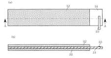
以下に、本発明をリチウムイオン電池に適用した場合の好ましい実施の形態を図1〜図7に基づいて説明するが、本発明はこの実施の形態に何ら限定されるものでなく、本発明の目的を変更しない範囲で適宜変更して実施することが可能である。なお、図1は本発明をリチウムイオン電池に適用するための正極板を模式的に示す図あり、図1(a)はその正面図であり、図1(b)は図1(a)のA−A断面を示す断面図である。図2は図1の正極板の一部に絶縁テープを貼着した状態の要部の断面を示す断面図である。図3はロール状に巻かれた絶縁テープを模式的に示す斜視図である。 Hereinafter, a preferred embodiment when the present invention is applied to a lithium ion battery will be described with reference to FIGS. 1 to 7. However, the present invention is not limited to this embodiment, and the present invention is not limited to this embodiment. It is possible to carry out by appropriately changing without changing the purpose. 1 is a diagram schematically showing a positive electrode plate for applying the present invention to a lithium ion battery, FIG. 1 (a) is a front view thereof, and FIG. 1 (b) is a diagram of FIG. 1 (a). It is sectional drawing which shows an AA cross section. FIG. 2 is a cross-sectional view showing a cross section of the main part in a state where an insulating tape is attached to a part of the positive electrode plate of FIG. FIG. 3 is a perspective view schematically showing an insulating tape wound in a roll shape.
また、図4は負極板を模式的に示す図あり、図4(a)はその正面図であり、図4(b)は図4(a)のA−A断面を示す断面図である。図5は正極板と負極板をセパレータを介して積層したものを渦巻状に巻回して渦巻状電極群を形成する状態を模式的に示す斜視図である。図6は渦巻状電極群を示す図であり、図6(a)は渦巻状電極群の横断面を示す断面図であり、図6(b)は図6(a)の要部を拡大して示す拡大断面図である。図7は変形例の製造方法の要部を模式的に示す断面図である。 4 is a diagram schematically showing the negative electrode plate, FIG. 4 (a) is a front view thereof, and FIG. 4 (b) is a cross-sectional view showing the AA cross section of FIG. 4 (a). FIG. 5 is a perspective view schematically showing a state where a spiral electrode group is formed by spirally winding a laminate of a positive electrode plate and a negative electrode plate with a separator interposed therebetween. 6 is a view showing a spiral electrode group, FIG. 6 (a) is a cross-sectional view showing a cross section of the spiral electrode group, and FIG. 6 (b) is an enlarged view of the main part of FIG. 6 (a). FIG. FIG. 7 is a cross-sectional view schematically showing a main part of a manufacturing method according to a modification.
1.正極
LiCoO2からなる正極活物質と、アセチレンブラック、グラファイト等の炭素系導電剤とからなる正極合剤に、結着剤としてのポリビニリデンフルオライト(PVDF)がN−メチルピロリドンからなる有機溶剤に溶解された結着剤溶液を混合して、スラリーあるいはペーストとした。これらのスラリーあるいはペーストを、スラリーの場合はダイコーター、ドクターブレード等を用いて、ペーストの場合はローラコーティング法等により正極芯体(例えば、厚みが15μmのアルミニウム箔)11の両面に均一に塗布して、活物質層12を塗布した正極活物質塗布板を形成した。
1. Positive electrode A positive electrode mixture composed of a positive electrode active material composed of LiCoO 2 and a carbon-based conductive agent such as acetylene black and graphite, and a polyvinylidene fluoride (PVDF) as a binder into an organic solvent composed of N-methylpyrrolidone. The dissolved binder solution was mixed to obtain a slurry or paste. Apply these slurries or pastes evenly on both sides of the positive electrode core (for example, an aluminum foil with a thickness of 15 μm) 11 by using a die coater, a doctor blade, etc. Thus, a positive electrode active material application plate coated with the
この後、正極活物質層12を塗布した正極活物質塗布板を乾燥機内に通過させて、スラリーあるいはペースト作製に必要であった有機溶剤を揮散させて除去し、乾燥させた。ついで、乾燥後の正極活物質塗布板を正極合剤の充填密度が3.7g/mlになるようにロールプレス機により圧延した後、所定の寸法(例えば、幅が56mmで、長さが630mm)になるように切断して正極板10を作製した。
Then, the positive electrode active material application | coating board which apply | coated the positive electrode
この場合、後述する渦巻状電極群が作製された際に、この渦巻状電極群の最内周部および最外周部に配置される部分には、正極芯体11に正極活物質層12が存在しない芯体露出部12a,12b,12c,12dを形成するようにしている。なお、芯体露出部12aは渦巻状電極群の最内周部の芯体12の内側に配置される部分であって、正極10の内周側端部から20mmまでは活物質の未塗布領域となるようになされている。
In this case, when a spiral electrode group, which will be described later, is produced, the positive electrode
また、芯体露出部12bは渦巻状電極群の最内周部の芯体12の外側に配置される部分であって、正極10の内周側端部から5mmまでは活物質の未塗布領域となるようになされている。さらに、芯体露出部12c,12dは渦巻状電極群の最外周部の芯体12の内側および外側に配置される部分であって、正極10の外周側端部から55mmまでは活物質の未塗布領域となるようになされている。そして、芯体露出部12aの端部側に正極集電タブ(正極リード)13が溶接されている。
Further, the core exposed
2.絶縁テープ
ついで、図3に示すように、所定幅(例えば、10mm)でロール状に巻かれた絶縁テープ20(x1,x2,x3,x4,x5,x6,x7)を用意した。この場合、絶縁テープ20(x1,x2,x3,x4,x5,x6,x7)としては、厚みが20μmのプリプロピレン(PP)からなる基材に、エチレン−アクリル酸エステル共重合体(EEA)からなる糊材の厚みが10μmになるように塗布されたものを用いている。そして、図2に示すように、a部、b部、c部およびd部の厚みが以下のようになるように、加熱ローラを用いて絶縁テープ20(x1,x2,x3,x4,x5,x6,x7)を成形している。
2. Insulating Tape Next, as shown in FIG. 3, an insulating tape 20 (x1, x2, x3, x4, x5, x6, x7) wound in a roll shape with a predetermined width (for example, 10 mm) was prepared. In this case, as the insulating tape 20 (x1, x2, x3, x4, x5, x6, x7), an ethylene-acrylate copolymer (EEA) is formed on a base material made of 20 μm thick propylene (PP). The paste applied with the thickness of 10 μm is used. Then, as shown in FIG. 2, the insulating tape 20 (x1, x2, x3, x4, x5) is used by using a heating roller so that the thicknesses of the a part, b part, c part and d part are as follows. x6, x7) are molded.
ここで、図2に示すように、a部(芯体11に貼着される幅0.5mmの端部部分)の厚みが30μmで、b部(芯体11に貼着される幅6.0mmのa部の端部から未塗布領域の端部までの部分)の厚みが30μmで、c部(活物質層12の端部に貼着される幅3.0mmの部分)の厚みが30μmで、d部(活物質層12に貼着される幅0.5mmの端部部分)の厚みが25μmとなる絶縁テープ20をテープx1とした。なお、c部のd部側にはc部からd部に向けて厚みが薄くなる傾斜部が形成されている。
Here, as shown in FIG. 2, the thickness of the part a (the end part having a width of 0.5 mm attached to the core body 11) is 30 μm, and the part b (the width attached to the core body 11). The thickness of the 0 mm a portion from the end of the a portion to the end of the uncoated region is 30 μm, and the c portion (the portion having a width of 3.0 mm attached to the end of the active material layer 12) is 30 μm. Thus, the insulating
同様に、a部の厚みが30μmで、b部の厚みが30μmで、c部の厚みが30μmで、d部の厚みが20μmとなる絶縁テープ20をテープx2とした。なお、この場合も、c部のd部側にはc部からd部に向けて厚みが薄くなる傾斜部が形成されている。また、a部の厚みが30μmで、b部の厚みが30μmで、c部の厚みが20μmで、d部の厚みが20μmとなる絶縁テープ20をテープx3とした。なお、この場合、b部のc部側にはb部からc部に向けて厚みが薄くなる傾斜部が形成されている。
Similarly, the insulating
また、a部の厚みが30μmで、b部の厚みが30μmで、c部の厚みが20μmで、d部の厚みが15μmとなる絶縁テープ20をテープx4とした。なお、この場合は、b部のc部側にはb部からc部に向けて厚みが薄くなる傾斜部が形成されているとともに、c部のd部側にはc部からd部に向けて厚みが薄くなる傾斜部が形成されている。
Further, an insulating
また、a部の厚みが20μmで、b部の厚みが30μmで、c部の厚みが20μmで、d部の厚みが15μmとなる絶縁テープ20をテープx5とした。なお、この場合は、b部のa部側にはb部からa部に向けて厚みが薄くなる傾斜部が形成されており、b部のc部側にはb部からc部に向けて厚みが薄くなる傾斜部が形成されており、さらに、c部のd部側にはc部からd部に向けて厚みが薄くなる傾斜部が形成されている。
さらに、a部、b部、c部およびd部の厚みが全て30μmとなる絶縁テープ20をテープx6とした。また、a部、b部、c部およびd部の厚みが全て20μmとなる絶縁テープ20をテープx7とした。
Also, an insulating
Furthermore, the insulating
なお、絶縁テープ20(x1,x2,x3,x4,x5,x6,x7)としては、上述した材質以外に、厚みが14〜30μmのプリプロピレン(PP)、ポリエチレンテレフタレート(PET)、ポリエチレンナフタレート(PAN)等からなる基材に、ゴム系粘着材、エチレン酢酸ビニール共重合体(EVA)、エチレン−アクリル酸エチル共重合体(EEA)、エチレン−メタクリル酸メチル共重合体(EMAA)等の糊材を厚みが10〜15μmになるように塗布したものを用いてもよい。 In addition, as the insulating tape 20 (x1, x2, x3, x4, x5, x6, x7), in addition to the above-mentioned materials, propylene (PP), polyethylene terephthalate (PET), polyethylene naphthalate having a thickness of 14 to 30 μm. (PAN) etc., such as rubber adhesive, ethylene vinyl acetate copolymer (EVA), ethylene-ethyl acrylate copolymer (EEA), ethylene-methyl methacrylate copolymer (EMAA), etc. You may use what applied the paste material so that thickness might be set to 10-15 micrometers.
そして、この正極10の芯体露出部12aと正極活物質層12との境界部、および芯体露出部12bと正極活物質層12との境界部に、それぞれ上述した絶縁テープ20(x1,x2,x3,x4,x5,x6,x7)を貼着し、これを正極a,b,c,d,e,x,yとした。なお、絶縁テープx1を貼着したものを正極aとし、絶縁テープx2を貼着したものを正極bとし、絶縁テープx3を貼着したものを正極cとし、絶縁テープx4を貼着したものを正極dとし、絶縁テープx5を貼着したものを正極eとした。また、絶縁テープx6を貼着したものを正極xとし、絶縁テープx7を貼着したものを正極yとした。
The insulating tape 20 (x1, x2) described above is formed at the boundary between the core exposed
3.負極
一方、負極活物質としての黒鉛(比表面積約3.0m2/g)と、増粘剤としてのカルボキシメチルセルロース(CMC)と、結着剤としてのスチレン−ブタジエンゴム(SBR)を質量比で95:3:2の割合で混合して負極合剤を調製した。この負極合剤に水を添加、混合してスラリーとした。この後、このスラリーを銅箔からなる負極集電体31の両面にドクターブレード法もしくはダイコート法により塗布して、負極活物質層32を形成した。
3. Negative electrode On the other hand, graphite as a negative electrode active material (specific surface area of about 3.0 m 2 / g), carboxymethyl cellulose (CMC) as a thickener, and styrene-butadiene rubber (SBR) as a binder in mass ratio. A negative electrode mixture was prepared by mixing at a ratio of 95: 3: 2. Water was added to the negative electrode mixture and mixed to obtain a slurry. Thereafter, this slurry was applied to both surfaces of a negative electrode
ついで、乾燥後の負極活物質塗布板をロールプレス機により圧延した後、所定の寸法(例えば、幅が56mmで、長さが630mm)になるように切断して負極30を作製した。なお、後述のように渦巻状電極群が作製された際に、最外周部に配置される負極30の両面には負極活物質層32が存在しない未塗布領域を形成して、この未塗布領域の端部側に負極集電タブ33を溶接している。
Next, the negative electrode active material-coated plate after drying was rolled by a roll press, and then cut to have predetermined dimensions (for example, a width of 56 mm and a length of 630 mm) to produce the
4.渦巻状電極群
ついで、上述のようにして作製された正極10(a,b,c,d,e,x,y)と負極30とを用いて、これらの間にセパレータ40(図5参照)を介在させて積層した後、これを巻き取り機により渦巻状に巻回して、渦巻状電極群A,B,C,D,E,X,Yをそれぞれ作製した。この場合、巻き取り機の巻芯(図示せず)の直径を3mmとし、巻き取り速度が500rpm、1000rpm、2000rpm、2500rpm、3000rpmになるように調整して、渦巻状電極群A,B,C,D,E,X,Yをそれぞれ作製した。
4). Spiral electrode group Next, the positive electrode 10 (a, b, c, d, e, x, y) and the
これらの渦巻状電極群A,B,C,D,E,X,Yの巻回時に箔切れが生じたか否かを検証するために、巻き取り後、これらの渦巻状電極群A,B,C,D,E,X,Yをそれぞれ解体して、箔切れが生じたか否かを確認した。その結果、下記の表1に示すような結果が得られた。なお、下記の表1においては、各電極群A,B,C,D,E,X,Yをそれぞれ30個ずつ用いた場合の結果を示していて、その30個の内の1個でも箔切れが生じたものを×印で表し、1個も箔切れが生じなかったものを○印で示している。

上記表1の結果から明らかなように、a部、b部、c部およびd部の厚みが全て30μmとなる絶縁テープ20(x6)を貼着した正極xを用いた渦巻状電極群X、およびa部、b部、c部およびd部の厚みが全て20μmとなる絶縁テープ20(x7)を貼着した正極y用いた渦巻状電極群Yにおいては、巻き取り速度が500rpmの低速であっても箔切れが生じて、これよりも低速度で巻回を行わないと正常な渦巻状電極群X,Yが生産できないことが分かる。 As is clear from the results in Table 1 above, the spiral electrode group X using the positive electrode x to which the insulating tape 20 (x6) having the thicknesses a, b, c, and d are all 30 μm is attached. In the spiral electrode group Y using the positive electrode y to which the insulating tape 20 (x7) having the thicknesses of all of the parts a, b, c and d is 20 μm, the winding speed is a low speed of 500 rpm. However, it can be seen that a foil breakage occurs, and normal spiral electrode groups X and Y cannot be produced unless winding is performed at a lower speed.
一方、a部、b部、c部の厚みが30μmで、d部の厚みが25μmとなる絶縁テープ20(x1)を貼着した正極aを用いた渦巻状電極群Aにおいては、巻き取り速度が500rpmでは箔切れが生じることがなく、巻き取り速度が1000rpmになると箔切れが生じることが分かる。また、a部、b部、c部の厚みが30μmで、d部の厚みが20μmとなる絶縁テープ20(x2)を貼着した正極bを用いた渦巻状電極群Bにおいては、巻き取り速度が500rpm,1000rpmでは箔切れが生じることがなく、巻き取り速度が2000rpmになると箔切れが生じることが分かる。 On the other hand, in the spiral electrode group A using the positive electrode a to which the insulating tape 20 (x1) in which the thickness of the a part, the b part, and the c part is 30 μm and the thickness of the d part is 25 μm, is taken up. However, it is understood that the foil breakage does not occur at 500 rpm, and the foil breakage occurs when the winding speed reaches 1000 rpm. Further, in the spiral electrode group B using the positive electrode b on which the insulating tape 20 (x2) having a thickness of a part, b part, and c part of 30 μm and a thickness of d part of 20 μm is attached, the winding speed However, at 500 rpm and 1000 rpm, the foil breakage does not occur, and when the winding speed is 2000 rpm, the foil breakage occurs.
また、a部、b部の厚みが30μmで、c部、d部の厚みが20μmとなる絶縁テープ20(x3)を貼着した正極cを用いた渦巻状電極群Cにおいては、巻き取り速度が500rpm,1000rpm,2000rpmでは箔切れが生じることがなく、巻き取り速度が2500rpmになると箔切れが生じることが分かる。また、a部、b部の厚みが30μmで、c部の厚みが20μmで、d部の厚みが15μmとなる絶縁テープ20(x4)を貼着した正極dを用いた渦巻状電極群Dにおいては、巻き取り速度が500rpm,1000rpm,2000rpm,2500rpmでは箔切れが生じることがなく、巻き取り速度が3000rpmになると箔切れが生じることが分かる。 Further, in the spiral electrode group C using the positive electrode c to which the insulating tape 20 (x3) having the thickness of the a part and the b part is 30 μm and the thickness of the c part and the d part is 20 μm, the winding speed is However, at 500 rpm, 1000 rpm, and 2000 rpm, the foil breakage does not occur, and when the winding speed is 2500 rpm, the foil breakage occurs. Further, in the spiral electrode group D using the positive electrode d to which the insulating tape 20 (x4) having the thickness of the part a and the part b is 30 μm, the thickness of the part c is 20 μm, and the thickness of the part d is 15 μm is attached. It can be seen that the foil breakage does not occur when the winding speed is 500 rpm, 1000 rpm, 2000 rpm, or 2500 rpm, and the foil breakage occurs when the winding speed is 3000 rpm.
さらに、a部の厚みが20μmで、b部の厚みが30μmで、c部の厚みが20μmで、d部の厚みが15μmとなる絶縁テープ20(x5)を貼着した正極eを用いた渦巻状電極群Eにおいては、巻き取り速度が500rpm,1000rpm,2000rpm,2500rpm,3000rpmでは箔切れが生じることがなく、このような3000rpmという高速度で巻回を行っても正常な渦巻状電極群Eが生産できることが分かる。 Furthermore, a spiral using a positive electrode e to which an insulating tape 20 (x5) having a thickness of a part of 20 μm, a thickness of b part of 30 μm, a thickness of c part of 20 μm, and a thickness of d part of 15 μm is attached. In the electrode group E, foil breakage does not occur when the winding speed is 500 rpm, 1000 rpm, 2000 rpm, 2500 rpm, and 3000 rpm. Even if the winding is performed at a high speed of 3000 rpm, a normal spiral electrode group E is obtained. Can be produced.
これは、正極芯体11となるアルミニウム箔に特にストレスが付与されやすいd部において、このd部の絶縁テープ20の厚みを30μmから25μm、25μmから20μm、20μmから15μmに薄くするに伴って、正極芯体11となるアルミニウム箔に付与されるストレスが低減されるためと考えられる。また、d部と同様に正極芯体11となるアルミニウム箔にストレスが付与されやすいc部において、このc部の絶縁テープ20の厚みを30μmから20μmに薄くするに伴って、正極芯体11となるアルミニウム箔に付与されるストレスが低減されるためと考えられる。さらに、d部、c部と同様に正極芯体11となるアルミニウム箔にストレスが付与されやすいa部において、このa部の絶縁テープ20の厚みを30μmから20μmに薄くするに伴って、正極芯体11となるアルミニウム箔に付与されるストレスが低減されるためと考えられる。
This is because, in the portion d where stress is particularly imparted to the aluminum foil serving as the
5.変形例
上述した例においては、予めa部、b部、c部およびd部の厚みが適宜異なるように形成した絶縁テープ20を用いて、この絶縁テープ20を正極板10の芯体露出部12aと正極活物質層12との境界部、および芯体露出部12bと正極活物質層12との境界部に貼着する例について説明したが、本発明はこれに限らず、種々の変形が可能であって、以下にその変形例の一例について説明する。
5. In the above-described example, the insulating
まず、上述のように作製された正極板10を用意するとともに、厚みが20μmのプリプロピレン(PP)からなる基材に、エチレン−アクリル酸エステル共重合体(EEA)からなる糊材の厚みが10μmになるように塗布された絶縁テープ20を用意した。この後、この正極板10の芯体露出部12aと正極活物質層12との境界部、および芯体露出部12bと正極活物質層12との境界部に、それぞれ絶縁テープ20を貼着した。
First, the
ついで、図7に示すように、a部を形成するための凸部51aを備えるとともに、b部のa部側に傾斜部を形成するための傾斜部51bを備えた第1加熱治具51と、d部を形成するための凸部52aを備えた第2加熱治具52とからなる成形型50を用意する。この成形型50を所定の温度(例えば、120℃)に加熱した後、絶縁テープ20が貼着された正極板10の上部に位置合わせして配置した。この後、成形型50を押し下げて、第1加熱治具51の凸部51aと傾斜部51b、および第2加熱治具52の凸部52aが絶縁テープ20の所定の位置に押し当たるようにした。
Next, as shown in FIG. 7, the
これにより、絶縁テープ20の第1加熱治具51の凸部51aと傾斜部51bおよび第2加熱治具52の凸部52aが押し当たった部分が溶融して、この部分の厚みが薄くなることとなる。この結果、正極板10に絶縁テープ20を貼着した後に、絶縁テープ20の所定の部位に厚みが薄い部分を容易に形成することができる。
As a result, the portions of the insulating
この変形例の製造方法によれば、予め厚みの薄い部分を形成した絶縁テープ20を用いる必要がなくなるので、この種の絶縁テープ20を安価に得ることができるようになる。また、厚みの異なる絶縁テープ20を所定の位置に貼着するための位置合わせも容易になるので、この種の絶縁テープ20が貼着された正極板を容易に製造することができるようになる。
According to the manufacturing method of this modified example, it is not necessary to use the insulating
なお、上述の実施形態においては、正極10の芯体露出部12aと正極活物質層12との境界部、および芯体露出部12bと正極活物質層12との境界部、即ち、渦巻状電極群の巻始端部側の芯体露出部12a,12bにそれぞれ絶縁テープ20を貼着した例について説明したが、これに限られず、正極10の芯体露出部12c,12dと正極活物質層12との境界部、あるいは負極30の芯体露出部と負極活物質層32との境界部にそれぞれ絶縁テープ20を貼着するようにしてもよい。また、負極の渦巻状電極群の巻始端部側に芯体露出部が形成されており、かつ正極の渦巻状電極群の巻始端部側にも芯体露出部が形成されている場合、これらの各芯体露出部と各活物質層との境界部にそれぞれ絶縁テープを貼着するのが望ましい。
In the above-described embodiment, the boundary between the core exposed
また、上述の実施形態においては、非水電解質電池の負極活物質として黒鉛を用いる例について説明したが、黒鉛以外に、リチウムイオンを吸蔵・脱離し得るカーボン系材料、例えば、グラファイト、カーボンブラック、コークス、ガラス状炭素、炭素繊維、またはこれらの焼成体等が好適である。また、シリカ系材料、酸化錫、酸化チタン等のリチウムイオンを吸蔵・脱離し得る酸化物を用いてもよい。 Further, in the above-described embodiment, an example in which graphite is used as a negative electrode active material of a nonaqueous electrolyte battery has been described. However, in addition to graphite, a carbon-based material that can occlude / desorb lithium ions, such as graphite, carbon black, Coke, glassy carbon, carbon fiber, or a fired body thereof is preferable. In addition, an oxide capable of inserting and extracting lithium ions such as silica-based material, tin oxide, and titanium oxide may be used.
また、上述の実施形態においては、非水電解質電池の正極活物質としてLiCoO2を用いる例について説明したが、LiCoO2以外に、リチウムイオンをゲストとして受け入れ得るリチウム含有遷移金属化合物、例えば、LiNiO2、LiCoXNi(1−X)O2、LiCrO2、LiVO2、LiMnO2、αLiFeO2、LiTiO2、LiScO2、LiYO2、LiMn2O4等が好ましいが、特に、LiNiO2、LiCoXNi(1−X)O2を単独で用いるかあるいはこれらの二種以上を混合して用いるのが好適である。また、ポリアセチレン、ポリアニリン等の導電性ポリマーを用いてもよい。 Further, in the above-described embodiment, an example in which LiCoO 2 is used as the positive electrode active material of the nonaqueous electrolyte battery has been described. However, in addition to LiCoO 2 , a lithium-containing transition metal compound that can accept lithium ions as a guest, for example, LiNiO 2 , LiCoXNi (1-X) O 2 , LiCrO 2 , LiVO 2 , LiMnO 2 , αLiFeO 2 , LiTiO 2 , LiScO 2 , LiYO 2 , LiMn 2 O 4, etc. are preferred, and in particular, LiNiO 2 , LiCoXNi (1-X It is preferable to use O 2 alone or in combination of two or more thereof. Further, a conductive polymer such as polyacetylene or polyaniline may be used.
さらに、上述の実施形態においては、本発明を円筒形の電池に適用する例について説明したが、円筒形に限らず、渦巻状電極群およびこれを押し潰して扁平にした電極群を用いる電池であれば、角形などの他の形状の電池に適用することが可能である。また、上述の実施形態においては、本発明をリチウムイオン電池に適用する例について説明したが、リチウムイオン電池以外に、芯体として金属箔を用いる場合は、ニッケル−カドミウム蓄電池、ニッケル−水素蓄電池などの各種の電池においても本発明を適用することが可能である。 Furthermore, in the above-described embodiment, an example in which the present invention is applied to a cylindrical battery has been described. However, the present invention is not limited to a cylindrical battery, and is a battery that uses a spiral electrode group and an electrode group that is flattened by crushing it. If it exists, it is possible to apply to batteries of other shapes such as a square. Moreover, in the above-mentioned embodiment, although the example which applies this invention to a lithium ion battery was demonstrated, when using metal foil as a core other than a lithium ion battery, nickel-cadmium storage battery, nickel-hydrogen storage battery, etc. The present invention can also be applied to various types of batteries.
10a…渦巻状電極群、10…正極板、11…正極芯体(金属箔)、12…正極活物質層、12a,12b,12c,12d…芯体露出部、13…正極集電タブ、20…絶縁テープ、30…負極板、31…負極芯体(金属箔)、32…負極活物質層、33…負極集電タブ、40…セパレータ、50…成形型、51…第1の加熱治具、51a…凸部、51b…傾斜部、52…第2の加熱治具、52a…凸部
DESCRIPTION OF SYMBOLS 10a ... Spiral electrode group, 10 ... Positive electrode plate, 11 ... Positive electrode core (metal foil), 12 ... Positive electrode active material layer, 12a, 12b, 12c, 12d ... Core body exposed part, 13 ... Positive electrode current collection tab, 20 DESCRIPTION OF SYMBOLS Insulation tape, 30 ... Negative electrode plate, 31 ... Negative electrode core (metal foil), 32 ... Negative electrode active material layer, 33 ... Negative electrode current collection tab, 40 ... Separator, 50 ... Mold, 51 ... 1st heating jig , 51a ... convex portion, 51b ... inclined portion, 52 ... second heating jig, 52a ... convex portion
Claims (5)
前記正極および負極の少なくとも一方は前記金属箔が露出する露出部を備えているとともに活物質塗布端部の近傍の少なくとも1箇所には該塗布端部の近傍から前記露出部に亘って絶縁テープが貼着されており、
前記貼着された絶縁テープは、前記露出部に貼着された該テープの一方の端部部分となるa部と、該a部の終端から前記活物質塗布端部までのb部と、前記活物質塗布端部から該活物質塗布端部の近傍までのc部と、前記活物質塗布部に貼着された前記c部の終端から他方の端縁までのd部とからなり、
前記a部、b部、c部およびd部の各部の厚みは、b部の厚み≧a部の厚み≧c部の厚み≧d部の厚み(ただし、a部、b部、c部およびd部の全ての厚みが等しくなることはない)の関係を有していることを特徴とする渦巻状電極群を備えた電池。 A spiral in which a positive electrode in which a positive electrode active material is applied to a positive electrode core made of metal foil and a negative electrode in which the negative electrode active material is applied to a negative electrode core made of metal foil are wound so as to face each other via a separator A battery provided with a group of electrode electrodes,
At least one of the positive electrode and the negative electrode has an exposed portion from which the metal foil is exposed, and at least one portion in the vicinity of the active material coating end portion has an insulating tape extending from the vicinity of the coating end portion to the exposed portion. Pasted,
The affixed insulating tape comprises a part that is one end part of the tape affixed to the exposed part, a part b from the end of the a part to the active material application end part, The c part from the active material application end to the vicinity of the active material application end, and the d part from the end of the c part adhered to the active material application part to the other edge,
The thickness of each of the a part, b part, c part and d part is as follows: the thickness of the part b ≧ the thickness of the part a ≧ the thickness of the part c ≧ the thickness of the part d (however, the parts a, b, c and d) A battery having a spiral electrode group characterized in that all the thicknesses of the portions are not equal) .
前記金属箔の端部側に該金属箔が露出した露出部を形成するように活物質を塗布する活物質塗布工程と、
前記露出部に貼着されて一方の端部部分となるa部と、該a部の終端から前記活物質塗布端部までのb部と、前記活物質塗布端部から該活物質塗布端部の近傍までのc部と、前記活物質塗布部に貼着されて前記c部の終端から他方の端縁までのd部とからなり、かつ、前記a部、b部、c部およびd部の各部の厚みは、b部の厚み≧a部の厚み≧c部の厚み≧d部の厚み(ただし、a部、b部、c部およびd部の全ての厚みが等しくなることはない)の関係を有するように形成された絶縁テープを前記活物質が塗布された活物質塗布端部の近傍の少なくとも1箇所に該塗布端部の近傍から前記露出部に亘って貼着する絶縁テープ貼着工程とを備えたことを特徴とする渦巻状電極群を備えた電池の製造方法。 A positive electrode obtained by applying a positive electrode active material to a positive electrode core made of a metal foil and a negative electrode obtained by applying a negative electrode active material to a negative electrode core made of a metal foil were wound in a spiral shape so as to face each other through a separator. A method of manufacturing a battery including a spiral electrode group,
An active material application step of applying an active material so as to form an exposed portion where the metal foil is exposed on the end side of the metal foil;
And a portion of the hand end portion of which is bonded to the exposed portion, and the portion b from the end of the a portion to the active material coating ends, said active material coating ends from said active material coating ends A portion c up to the vicinity of the portion, and a portion d bonded to the active material application portion and from the end of the portion c to the other edge, and the portions a, b, c, and d The thickness of each part of the part is the thickness of the part b ≧ the thickness of the part a ≧ the thickness of the part c ≧ the thickness of the part d (however, all the thicknesses of the parts a, b, c, and d are not equal) Insulating tape that adheres an insulating tape formed so as to have a relationship of (1) to at least one location in the vicinity of the active material application end portion coated with the active material from the vicinity of the application end portion to the exposed portion. A manufacturing method of a battery provided with a spiral electrode group, comprising: an attaching step.
前記金属箔の端部側に該金属箔が露出した露出部を形成するように活物質を塗布する活物質塗布工程と、
前記活物質が塗布された活物質塗布端部の近傍の少なくとも1箇所に絶縁テープを貼着する絶縁テープ貼着工程と、
前記露出部に貼着された前記テープの一方の端部部分となるa部と、該a部の終端から前記活物質塗布端部までのb部と、前記活物質塗布端部から該活物質塗布塗布端部の近傍までのc部と、前記活物質塗布部に貼着された前記c部の終端から他方の端縁までのd部とからなり、かつ、前記a部、b部、c部およびd部の各部の厚みは、b部の厚み≧a部の厚み≧c部の厚み≧d部の厚み(ただし、a部、b部、c部およびd部の全ての厚みが等しくなることはない)の関係を有するように前記絶縁テープを加熱加圧する加熱加圧工程とを備えたことを特徴とする渦巻状電極群を備えた電池の製造方法。 A positive electrode obtained by applying a positive electrode active material to a positive electrode core made of a metal foil and a negative electrode obtained by applying a negative electrode active material to a negative electrode core made of a metal foil were wound in a spiral shape so as to face each other through a separator. A method of manufacturing a battery including a spiral electrode group,
An active material application step of applying an active material so as to form an exposed portion where the metal foil is exposed on the end side of the metal foil;
An insulating tape attaching step of attaching an insulating tape to at least one location in the vicinity of the active material application end where the active material is applied;
And a portion to be bonded has been one end portion of the tape on the exposed portion, and the portion b from the end of the a portion to the active material coating ends, active material from the active material coating ends It consists of c part to the vicinity of the application | coating application | coating edge part, and d part from the termination | terminus of the said c part stuck to the said active material application part to the other edge, and said a part, b part, c The thickness of each part of the part and the part d is the thickness of the part b ≧ the thickness of the part a ≧ the thickness of the part c ≧ the thickness of the part d (however, all the thicknesses of the parts a, b, c, and d are equal) And a heating and pressurizing step for heating and pressurizing the insulating tape so as to have a relationship of (No) . A method for manufacturing a battery having a spiral electrode group.
前記金属箔の端部側に該金属箔が露出した露出部を形成するように活物質を塗布する活物質塗布工程と、
前記露出部に貼着されて一方の端部部分となるa部と、該a部の終端から前記活物質塗布端部までのb部と、前記活物質塗布端部から該活物質塗布塗布端部の近傍までのc部と、前記活物質塗布部に貼着されて前記c部の終端から他方の端縁までのd部とが形成され、かつ、前記a部、b部、c部およびd部の各部の厚みは、b部の厚み≧a部の厚み≧c部の厚み≧d部の厚み(ただし、a部、b部、c部およびd部の全ての厚みが等しくなることはない)の関係を有するように絶縁テープを加熱加圧する加熱加圧工程と、
前記加熱加圧された絶縁テープを前記活物質が塗布された活物質塗布端部の近傍の少なくとも1箇所に貼着する絶縁テープ貼着工程とを備えたことを特徴とする渦巻状電極群を備えた電池の製造方法。 A positive electrode obtained by applying a positive electrode active material to a positive electrode core made of a metal foil and a negative electrode obtained by applying a negative electrode active material to a negative electrode core made of a metal foil were wound in a spiral shape so as to face each other through a separator. A method of manufacturing a battery including a spiral electrode group,
An active material application step of applying an active material so as to form an exposed portion where the metal foil is exposed on the end side of the metal foil;
And a portion of the hand end portion of which is bonded to the exposed portion, and the portion b from the end of the a portion to the active material coating ends, said active material coating applied from said active material coating ends A c portion up to the vicinity of the end portion, and a d portion which is adhered to the active material application portion and extends from the terminal end of the c portion to the other end edge, and the a portion, the b portion, and the c portion The thickness of each part of the part d and the part d is the thickness of the part b ≧ the thickness of the part a ≧ the thickness of the part c ≧ the thickness of the part d (provided that the thicknesses of the parts a, b, c, and d are all equal) A heating and pressing step of heating and pressing the insulating tape so as to have a relationship of
A spiral electrode group comprising: an insulating tape adhering step for adhering the heat-pressed insulating tape to at least one location in the vicinity of an active material application end where the active material is applied; The manufacturing method of the battery provided.
Priority Applications (1)
| Application Number | Priority Date | Filing Date | Title |
|---|---|---|---|
| JP2004039623A JP4707328B2 (en) | 2004-02-17 | 2004-02-17 | Battery having spiral electrode group and manufacturing method thereof |
Applications Claiming Priority (1)
| Application Number | Priority Date | Filing Date | Title |
|---|---|---|---|
| JP2004039623A JP4707328B2 (en) | 2004-02-17 | 2004-02-17 | Battery having spiral electrode group and manufacturing method thereof |
Publications (2)
| Publication Number | Publication Date |
|---|---|
| JP2005235414A JP2005235414A (en) | 2005-09-02 |
| JP4707328B2 true JP4707328B2 (en) | 2011-06-22 |
Family
ID=35018164
Family Applications (1)
| Application Number | Title | Priority Date | Filing Date |
|---|---|---|---|
| JP2004039623A Expired - Fee Related JP4707328B2 (en) | 2004-02-17 | 2004-02-17 | Battery having spiral electrode group and manufacturing method thereof |
Country Status (1)
| Country | Link |
|---|---|
| JP (1) | JP4707328B2 (en) |
Families Citing this family (17)
| Publication number | Priority date | Publication date | Assignee | Title |
|---|---|---|---|---|
| KR100601550B1 (en) | 2004-07-28 | 2006-07-19 | 삼성에스디아이 주식회사 | Lithium Ion Secondary battery |
| KR100579376B1 (en) * | 2004-10-28 | 2006-05-12 | 삼성에스디아이 주식회사 | Secondary battery |
| JP4259476B2 (en) * | 2005-02-08 | 2009-04-30 | パナソニック株式会社 | Organic electrolyte primary battery |
| JP4839746B2 (en) * | 2005-09-16 | 2011-12-21 | ソニー株式会社 | Cylindrical non-aqueous electrolyte secondary battery |
| JP5002965B2 (en) * | 2006-01-20 | 2012-08-15 | ソニー株式会社 | Non-aqueous electrolyte battery and manufacturing apparatus thereof |
| JP2007242518A (en) * | 2006-03-10 | 2007-09-20 | Sanyo Electric Co Ltd | Square battery |
| JP4983299B2 (en) * | 2007-02-22 | 2012-07-25 | ソニー株式会社 | Non-aqueous electrolyte secondary battery and method for producing non-aqueous electrolyte secondary battery |
| KR101025277B1 (en) | 2007-10-30 | 2011-03-29 | 삼성에스디아이 주식회사 | Electrode assembly and secondary battery using the same |
| CN201430189Y (en) * | 2009-05-31 | 2010-03-24 | 比亚迪股份有限公司 | Lithium ion battery |
| JP5626170B2 (en) * | 2011-09-28 | 2014-11-19 | パナソニック株式会社 | battery |
| JP6152798B2 (en) * | 2011-12-12 | 2017-06-28 | 日立化成株式会社 | Nonaqueous electrolyte battery electrode group and nonaqueous electrolyte battery |
| JP2015109135A (en) * | 2012-03-14 | 2015-06-11 | 日産自動車株式会社 | Electrode, manufacturing method thereof and manufacturing device |
| CN108140903B (en) * | 2016-01-27 | 2021-11-12 | 日本汽车能源株式会社 | Secondary battery and method for manufacturing same |
| JP6834139B2 (en) * | 2016-02-10 | 2021-02-24 | 株式会社Gsユアサ | Power storage element |
| CN110337752B (en) * | 2017-03-28 | 2023-04-28 | 三洋电机株式会社 | Nonaqueous electrolyte secondary battery |
| JPWO2020170543A1 (en) * | 2019-02-19 | 2021-12-16 | 三洋電機株式会社 | Manufacturing method of non-aqueous electrolyte secondary battery and positive electrode plate used for it |
| CN116134633A (en) * | 2020-08-18 | 2023-05-16 | 三洋电机株式会社 | Nonaqueous electrolyte secondary battery |
Citations (3)
| Publication number | Priority date | Publication date | Assignee | Title |
|---|---|---|---|---|
| JPH10321252A (en) * | 1997-05-16 | 1998-12-04 | Hitachi Maxell Ltd | Battery comprising electrode body with rolled structure |
| JPH11111331A (en) * | 1997-10-07 | 1999-04-23 | Hitachi Maxell Ltd | Hydride secondary battery |
| JPH11297349A (en) * | 1998-04-09 | 1999-10-29 | Nitto Denko Corp | Adhesive tape or sheet for battery |
-
2004
- 2004-02-17 JP JP2004039623A patent/JP4707328B2/en not_active Expired - Fee Related
Patent Citations (3)
| Publication number | Priority date | Publication date | Assignee | Title |
|---|---|---|---|---|
| JPH10321252A (en) * | 1997-05-16 | 1998-12-04 | Hitachi Maxell Ltd | Battery comprising electrode body with rolled structure |
| JPH11111331A (en) * | 1997-10-07 | 1999-04-23 | Hitachi Maxell Ltd | Hydride secondary battery |
| JPH11297349A (en) * | 1998-04-09 | 1999-10-29 | Nitto Denko Corp | Adhesive tape or sheet for battery |
Also Published As
| Publication number | Publication date |
|---|---|
| JP2005235414A (en) | 2005-09-02 |
Similar Documents
| Publication | Publication Date | Title |
|---|---|---|
| JP4707328B2 (en) | Battery having spiral electrode group and manufacturing method thereof | |
| JP6296569B2 (en) | Positive electrode including insulating layer on positive electrode tab and secondary battery including the same | |
| US9755213B2 (en) | Cathode including insulation layer on cathode tab and secondary battery including the cathode | |
| JP4075034B2 (en) | Nonaqueous electrolyte battery and manufacturing method thereof | |
| JP4347759B2 (en) | Electrode manufacturing method | |
| WO2006106731A1 (en) | Cylindrical lithium secondary battery | |
| CN205810932U (en) | There is the lithium ion battery of spiral helicine winding arrangement | |
| CN110429328B (en) | Method for improving internal temperature rise of battery | |
| JP4031635B2 (en) | Electrochemical devices | |
| WO2017010046A1 (en) | Wound type battery | |
| JP4043956B2 (en) | Manufacturing method of battery electrode plate | |
| US20110293996A1 (en) | Stacked secondary battery and production method thereof | |
| JP3821434B2 (en) | Battery electrode group and non-aqueous electrolyte secondary battery using the same | |
| JP4251882B2 (en) | Nonaqueous electrolyte secondary battery | |
| CN114447408A (en) | Battery and electronic equipment | |
| JP2001283927A (en) | Nonaqueous secondary battery and its manufacturing method | |
| JP2000208129A (en) | Lithium secondary battery | |
| JP4245429B2 (en) | Battery with spiral electrode group | |
| JP3763233B2 (en) | Flat battery and method of manufacturing the same | |
| JP4636920B2 (en) | Battery with spiral electrode | |
| JP3168783B2 (en) | Negative electrode plate for non-aqueous electrolyte secondary battery and method for producing the same | |
| CN217103675U (en) | Adhesive tape and lithium battery | |
| CN114141982B (en) | Pole piece and battery | |
| JP2002175839A (en) | Sealed battery | |
| JP2006302509A (en) | Battery |
Legal Events
| Date | Code | Title | Description |
|---|---|---|---|
| A621 | Written request for application examination |
Free format text: JAPANESE INTERMEDIATE CODE: A621 Effective date: 20070215 |
|
| A977 | Report on retrieval |
Free format text: JAPANESE INTERMEDIATE CODE: A971007 Effective date: 20090428 |
|
| A131 | Notification of reasons for refusal |
Free format text: JAPANESE INTERMEDIATE CODE: A131 Effective date: 20090526 |
|
| A521 | Written amendment |
Free format text: JAPANESE INTERMEDIATE CODE: A523 Effective date: 20090723 |
|
| A131 | Notification of reasons for refusal |
Free format text: JAPANESE INTERMEDIATE CODE: A131 Effective date: 20100601 |
|
| A521 | Written amendment |
Free format text: JAPANESE INTERMEDIATE CODE: A523 Effective date: 20100714 |
|
| A01 | Written decision to grant a patent or to grant a registration (utility model) |
Free format text: JAPANESE INTERMEDIATE CODE: A01 Effective date: 20110215 |
|
| A61 | First payment of annual fees (during grant procedure) |
Free format text: JAPANESE INTERMEDIATE CODE: A61 Effective date: 20110315 |
|
| LAPS | Cancellation because of no payment of annual fees |