WO2017010046A1 - Wound type battery - Google Patents
Wound type battery Download PDFInfo
- Publication number
- WO2017010046A1 WO2017010046A1 PCT/JP2016/002942 JP2016002942W WO2017010046A1 WO 2017010046 A1 WO2017010046 A1 WO 2017010046A1 JP 2016002942 W JP2016002942 W JP 2016002942W WO 2017010046 A1 WO2017010046 A1 WO 2017010046A1
- Authority
- WO
- WIPO (PCT)
- Prior art keywords
- electrode
- current collector
- collector sheet
- active material
- uncoated
- Prior art date
Links
Images


Classifications
-
- H—ELECTRICITY
- H01—ELECTRIC ELEMENTS
- H01M—PROCESSES OR MEANS, e.g. BATTERIES, FOR THE DIRECT CONVERSION OF CHEMICAL ENERGY INTO ELECTRICAL ENERGY
- H01M6/00—Primary cells; Manufacture thereof
- H01M6/04—Cells with aqueous electrolyte
- H01M6/06—Dry cells, i.e. cells wherein the electrolyte is rendered non-fluid
- H01M6/10—Dry cells, i.e. cells wherein the electrolyte is rendered non-fluid with wound or folded electrodes
-
- H—ELECTRICITY
- H01—ELECTRIC ELEMENTS
- H01M—PROCESSES OR MEANS, e.g. BATTERIES, FOR THE DIRECT CONVERSION OF CHEMICAL ENERGY INTO ELECTRICAL ENERGY
- H01M10/00—Secondary cells; Manufacture thereof
- H01M10/04—Construction or manufacture in general
- H01M10/0431—Cells with wound or folded electrodes
-
- H—ELECTRICITY
- H01—ELECTRIC ELEMENTS
- H01M—PROCESSES OR MEANS, e.g. BATTERIES, FOR THE DIRECT CONVERSION OF CHEMICAL ENERGY INTO ELECTRICAL ENERGY
- H01M50/00—Constructional details or processes of manufacture of the non-active parts of electrochemical cells other than fuel cells, e.g. hybrid cells
- H01M50/10—Primary casings, jackets or wrappings of a single cell or a single battery
- H01M50/183—Sealing members
- H01M50/186—Sealing members characterised by the disposition of the sealing members
-
- H—ELECTRICITY
- H01—ELECTRIC ELEMENTS
- H01M—PROCESSES OR MEANS, e.g. BATTERIES, FOR THE DIRECT CONVERSION OF CHEMICAL ENERGY INTO ELECTRICAL ENERGY
- H01M10/00—Secondary cells; Manufacture thereof
- H01M10/05—Accumulators with non-aqueous electrolyte
- H01M10/052—Li-accumulators
-
- H—ELECTRICITY
- H01—ELECTRIC ELEMENTS
- H01M—PROCESSES OR MEANS, e.g. BATTERIES, FOR THE DIRECT CONVERSION OF CHEMICAL ENERGY INTO ELECTRICAL ENERGY
- H01M10/00—Secondary cells; Manufacture thereof
- H01M10/05—Accumulators with non-aqueous electrolyte
- H01M10/058—Construction or manufacture
- H01M10/0587—Construction or manufacture of accumulators having only wound construction elements, i.e. wound positive electrodes, wound negative electrodes and wound separators
-
- Y—GENERAL TAGGING OF NEW TECHNOLOGICAL DEVELOPMENTS; GENERAL TAGGING OF CROSS-SECTIONAL TECHNOLOGIES SPANNING OVER SEVERAL SECTIONS OF THE IPC; TECHNICAL SUBJECTS COVERED BY FORMER USPC CROSS-REFERENCE ART COLLECTIONS [XRACs] AND DIGESTS
- Y02—TECHNOLOGIES OR APPLICATIONS FOR MITIGATION OR ADAPTATION AGAINST CLIMATE CHANGE
- Y02E—REDUCTION OF GREENHOUSE GAS [GHG] EMISSIONS, RELATED TO ENERGY GENERATION, TRANSMISSION OR DISTRIBUTION
- Y02E60/00—Enabling technologies; Technologies with a potential or indirect contribution to GHG emissions mitigation
- Y02E60/10—Energy storage using batteries
-
- Y—GENERAL TAGGING OF NEW TECHNOLOGICAL DEVELOPMENTS; GENERAL TAGGING OF CROSS-SECTIONAL TECHNOLOGIES SPANNING OVER SEVERAL SECTIONS OF THE IPC; TECHNICAL SUBJECTS COVERED BY FORMER USPC CROSS-REFERENCE ART COLLECTIONS [XRACs] AND DIGESTS
- Y02—TECHNOLOGIES OR APPLICATIONS FOR MITIGATION OR ADAPTATION AGAINST CLIMATE CHANGE
- Y02P—CLIMATE CHANGE MITIGATION TECHNOLOGIES IN THE PRODUCTION OR PROCESSING OF GOODS
- Y02P70/00—Climate change mitigation technologies in the production process for final industrial or consumer products
- Y02P70/50—Manufacturing or production processes characterised by the final manufactured product
Definitions
- the present invention relates to a wound battery, and more particularly to a wound battery including a cylindrical metal can having a small outer diameter.
- Patent Document 1 teaches a battery including a small cylindrical metal can and a sealing member that seals the opening.
- the metal can contains a wound electrode group.
- the electrode group includes first and second electrodes, and a separator is interposed between the electrodes.
- a separator protrudes from the end face of the electrode group to prevent contact between an electrode having a different polarity and a battery can and a short circuit between the end of one electrode and the end of the other electrode.
- one aspect of the present disclosure includes a power generation element and a battery case that houses the power generation element, and the power generation element includes a first electrode, a second electrode having a polarity different from the first electrode, A separator interposed between the first electrode and the second electrode; and an electrolyte.
- the first electrode and the second electrode are wound through a separator to form an electrode group having a first end face and a second end face opposite to the first end face.
- the first electrode is a first current collector sheet And a first active material layer formed on the surface of the first current collector sheet.
- a first current collector lead is connected to the first electrode, and the second electrode includes a second current collector sheet and a second active material layer formed on the surface of the second current collector sheet.
- a second current collecting lead is connected to the second electrode, and at least one of an end disposed on the first end face of the first electrode and an end disposed on the second end face of the first electrode; Relates to a wound-type battery in which a winding end portion arranged on the outermost periphery of the electrode group is cut out.
- FIG. 1 is a diagram schematically illustrating a first electrode in which a first current collecting lead is connected to a first uncoated portion
- FIG. 1 (a) is a diagram illustrating a first current collecting lead connected to a first uncoated portion
- FIG. 4B is a plan view schematically showing the first electrode formed
- FIG. 2 is a diagram illustrating a positional relationship between the end portion of the end portion of the first electrode and the separator when the separator is bent.
- FIG. 3 is an explanatory diagram of the dimensions of the notches formed in the first electrode.
- FIG. 4 is a diagram showing variations of the shape of the notch.
- FIG. 5 is a diagram schematically illustrating a first electrode in which a first current collecting lead is connected to a first uncoated portion and the first uncoated portion is covered with an insulating layer.
- 1 is a plan view schematically showing a first electrode in which a first current collecting lead is connected to an uncoated portion and the first uncoated portion is covered with an insulating layer, and (b) is a sectional view taken along line IIb-IIb. It is.
- FIG. 6 is a diagram illustrating a state where the outer peripheral insulating layer is pulled toward the center of the electrode group at the end of the first electrode when viewed from the first end face side of the electrode group.
- FIG. 7 is a diagram schematically illustrating a second electrode in which a second current collecting lead is connected to a second uncoated portion
- (a) is a diagram illustrating a second current collecting lead connected to a second uncoated portion
- FIG. 3B is a cross-sectional view taken along line IIIb-IIIb, schematically showing the second electrode formed.
- FIG. 8 is a plan view schematically showing the configuration of the electrode group before winding.
- FIG. 9 is a plan view schematically showing another configuration of the electrode group before winding.
- FIG. 10 is a longitudinal sectional view of a cylindrical battery according to an embodiment of the present invention.
- a wound battery according to the present disclosure includes a power generation element and a battery case that houses the power generation element.
- the power generation element includes a first electrode, a second electrode having a polarity different from the first electrode, A separator interposed between the first electrode and the second electrode; and an electrolyte.
- the first electrode and the second electrode are wound through a separator to form an electrode group having a first end face and a second end face opposite to the first end face.
- the first electrode includes a first current collector sheet and a first active material layer formed on the surface of the first current collector sheet.
- a first current collecting lead is connected to the first electrode.
- the second electrode includes a second current collector sheet and a second active material layer formed on the surface of the second current collector sheet.
- a second current collecting lead is connected to the second electrode.
- At least one of the end portion disposed on the first end surface of the first electrode and the end portion disposed on the second end surface of the first electrode is cut.
- a notch is formed.
- the battery case includes, for example, a bottomed cylindrical metal can and a sealing member that closes the opening of the metal can.
- one of the first current collecting lead and the second current collecting lead is electrically connected to the sealing member, and the other is electrically connected to the inner surface of the metal can.
- welding is desirable.
- the importance of the notch formed in the first electrode is that the first current collecting lead is electrically connected to the sealing member and the second current collecting lead is electrically connected to the inner surface of the metal case. In particular, it becomes larger.
- the first electrode has a polarity different from that of the metal can, it is important to prevent contact between the inner surface of the metal can and the end portion of the first electrode. By cutting out the end portion of the first electrode arranged on the end surface of the electrode group, the end portion of the electrode group arranged on the outermost periphery of the electrode group is less likely to come into contact with the inner surface of the metal can.
- the length of the notch seen from the end face side of the electrode group is not particularly limited. From the balance between the ease of manufacturing the electrode and the short-circuit preventing effect, for example, it may be 1% or more of the length of the portion arranged on the outermost periphery of the first electrode, and may be 100% or less. From the viewpoint of obtaining a sufficient effect of preventing short circuit, the length of the notch is preferably 3% or more of the length of the portion arranged on the outermost periphery of the first electrode, and more preferably 5% or more. Further, considering the ease of manufacturing a mold for forming a notch, it is preferably 50% or less, more preferably 30% or less.
- the shape of the notch is not particularly limited, but is preferably rectangular in consideration of the ease of the process of forming the notch.
- the first current collecting lead When the first end face of the electrode group is disposed on the opening side of the metal can, the first current collecting lead may be extended from the first end face toward the opening side. Thereby, it becomes easy to electrically connect the first current collecting lead to the sealing member.
- the first current collector sheet has a first uncoated portion that does not have the first active material layer on both surfaces at the end portion arranged on the first end surface of the electrode group.
- the first current collecting lead is connected to the first uncoated portion. This eliminates the need to provide an uncoated portion for connecting the first current collector lead at the end of the first current collector sheet in the direction perpendicular to the winding axis direction. Unnecessary increases can be avoided. In this case, at least the end portion of the first uncoated portion is cut off. This is because, in the first uncoated portion, the first current collector sheet is exposed, and thus it is highly important to suppress a short circuit due to misalignment.
- the first uncoated portion may be formed with an insulating layer that covers the edge surface of the first uncoated portion and covers the surfaces on both sides of the first uncoated portion so as to enclose the notch. desirable.
- the presence of the insulating layer further suppresses the occurrence of a short circuit due to misalignment.
- the insulating layer is preferably an insulating tape having an insulating sheet and an adhesive layer provided on one surface of the insulating sheet. If such an insulating tape is used, the operation
- the first uncoated portion may be sandwiched between the front and back sides with the insulating tape so that the edge surface of the first uncoated portion is covered.
- the insulating layer projects from the edge surface of the first uncoated part.
- the probability of occurrence of an internal short circuit is further reduced, and the root of the first current collecting lead (the vicinity of the end face of the first uncoated portion) is fixed by the insulating layer, and the movement of the first current collecting lead is suppressed.
- the insulating layer desirably projects from the edge surface of the first uncoated portion along the entire length of the first electrode disposed on the first end surface.
- the end portion of the separator protrudes from the edge surface of the first uncoated portion. Thereby, the risk of an internal short circuit can be further reduced. Moreover, it is preferable that the edge part of a 1st uncoated part protrudes rather than the edge part of a 2nd collector sheet. Thereby, the strong connection between the first uncoated portion and the first current collecting lead is possible.
- the end portion of the separator When the insulating layer protrudes from the edge surface of the first uncoated portion on the first end surface, the end portion of the separator needs to protrude from the edge surface of the first uncoated portion to the first end surface side. There is no. However, it is preferable that the end portion of the separator protrudes toward the first end face side than the end portion on the side where the notch is finished. This is because the outermost end portion of the notch at the end of the cutting is most susceptible to positional shift and is likely to cause an internal short circuit.
- the first current collecting lead From the viewpoint of fixing the root of the first current collecting lead, it is not always necessary to cover the entire first uncoated portion with the insulating layer. However, it is preferable that at least an overlapping portion between the first current collecting lead and the first uncoated portion is covered with an insulating layer. Moreover, it is preferable that 90% or more of the first uncoated portion is covered with an insulating layer. By covering 90% or more of the total area of both surfaces of the first uncoated portion with the insulating layer, the effect of reducing the risk of internal short circuit is further increased.
- the outer insulating layer is pulled toward the center of the electrode group due to the difference in curvature. Therefore, when there is no notch in the end portion of the first uncoated portion, the end portion of the end portion of the first uncoated portion may be exposed. On the other hand, the presence of a notch in the end portion of the first uncoated portion ensures the short-circuit preventing effect of the insulating layer.
- a second uncoated portion having no second active material layer is formed on at least one surface. It is preferable.
- the second current collecting lead is connected to the second uncoated portion. Thereby, the connection location of the 2nd current collection lead can be secured, and it becomes easy to make the 2nd current collection lead extend toward the opening side from the 1st end face. Therefore, when a cylindrical metal can having a small outer diameter is used, an operation of electrically connecting the second current collecting lead to the inner surface of the metal can can be performed near the opening of the metal can.
- the second uncoated portion is preferably provided in a strip shape along the one end portion.
- the 2nd current collection lead can be firmly connected to the 2nd uncoated part by welding.
- the other end portion of the second current collector sheet in the direction perpendicular to the winding axis may be coincident with the end portion of the second active material layer, and the second current collector sheet is exposed.
- An uncoated portion may be provided.
- Such an uncoated part is also preferably provided in a strip shape along the other end part.
- Both ends in the winding axis direction of the electrode group of the second current collector sheet coincide with both ends in the same direction of the second active material layer. It is preferable. That is, it is preferable that the second active material layer is formed on both surfaces of both ends in the winding axis direction. Thereby, the opposing area of a 2nd active material layer and a 1st active material layer can be enlarged enough. Moreover, the risk of the internal short circuit by the contact with a 2nd collector sheet and a 1st uncoated part can be reduced significantly.
- each edge part does not need to be covered with the 2nd active material layer over the full length. For example, 50% or more of the total length of each end portion only needs to be covered with the second active material layer.
- both ends in the direction perpendicular to the winding axis direction of the first current collector sheet coincide with both ends in the same direction of the first active material layer. That is, it is preferable that the first active material layer is formed on both surfaces of both end portions in the direction perpendicular to the winding axis direction. Thereby, the opposing area of a 1st active material layer and a 2nd active material layer can be enlarged enough. Again, it is not necessary to cover the edge surface of each end with the first active material layer. Further, it is sufficient that 50% or more of the total length of each end portion is covered with the first active material layer.
- the importance of forming the notch in the first electrode is particularly significant when the battery case is, for example, a cylindrical shape having an outer diameter of 10 mm or less, further 6 mm or less, particularly 4.5 mm or less.
- the outer diameter of the battery case for example, the outer diameter of the cross section perpendicular to the axial direction of the metal can
- the positional deviation caused by the difference in curvature between the inner and outer circumferences, the winding deviation in the winding axis direction This is because bending is likely to occur.
- the metal can is preferably made of stainless steel from the viewpoint of securing strength, and the can wall preferably has a thickness of 0.05 mm to 0.2 mm. Thereby, a small-sized, high-capacity and high-strength wound battery can be realized. In addition, it is difficult to make the outer diameter of a cylindrical metal can smaller than 1 mm, and it is preferable that an outer diameter is 1 mm or more.
- the winding axis direction of the electrode group is also referred to as “first direction”, and the direction perpendicular to the winding axis direction is also referred to as “second direction”.
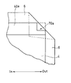
- the positive electrode 4 includes a positive electrode current collector sheet 40 that is a first current collector sheet, and a positive electrode active material layer 41 formed on both surfaces of the positive electrode current collector sheet 40.
- the positive electrode current collector sheet 40 is rectangular, and in the case of the present embodiment, the long side direction (Y direction in FIG. 1) coincides with the winding axis direction (first direction).
- a first uncoated portion 40a from which the positive electrode current collector sheet 40 is exposed is provided at one end portion (hereinafter, referred to as a first end portion) in the first direction. The first end is disposed on the first end face side of the electrode group.
- the first uncoated portion 40a is provided in a strip shape along the first end portion.
- One end of a strip-like positive electrode current collector lead 24 is connected to the first uncoated part 40a by welding.
- the right side (Out) of the arrow Aa displayed in FIG. 1 (a) is the winding end side arranged on the outermost periphery of the electrode group.
- the left side (In) of the arrow Aa is the center side of the electrode group (the starting side).
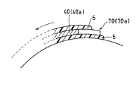
- rectangular first cutouts 70a and second cutouts 80a are formed in the rolling end portion 70 and the winding start portion 80 of the first uncoated portion 40a, respectively.
- the first notch 70a By forming the first notch 70a in the end portion 70, for example, as shown in FIG. 2, when the corner of the separator 6 is bent, the end portion 70 at the end of the first electrode protrudes from the separator. Probability decreases. Note that the second notch 80a is not necessarily formed at the center of the electrode group because the separator is unlikely to be bent or torn.
- the length W1 of the first notch 70a viewed from the end face side of the electrode group may be 1% to 100% of the length W2 of the portion arranged on the outermost periphery of the first electrode 4, and 3% to 50%. %, Preferably 5% to 30%.
- the specific length W1 may be, for example, 0.1 mm to 5 mm, and is preferably 1 mm to 3 mm.
- the length W2 may be selected according to the outer diameter of the metal can or the battery capacity, but is, for example, 5 mm to 15 mm, and is preferably 7 mm to 11 mm from the viewpoint of downsizing and slimming of the battery.
- the maximum length (height) W3 of the first notch 70a in the winding axis direction is not particularly limited, but is preferably 10 to 100% of the width W11 of the first uncoated portion 40a.
- the length of the second notch 80a viewed from the end face side of the electrode group is not particularly limited, but may be, for example, 1% to 250% or 10% to 250% of W1.
- the maximum length (height) of the second notch 80a in the winding axis direction is preferably 95 to 105% of the height W3, and more preferably the same as the height W3.
- the shape of the notch is not limited to a rectangle, and may be any shape.
- a tapered (wedge-shaped) notch 70b as shown in FIG. 4A an arc-like notch 70c as shown in FIG. 4B, and an R-shape as shown in FIG. 4C.
- a notch 70d or the like may be used.
- the positive electrode current collector sheet is not exposed at the other end portion in the first direction of the positive electrode 4 (hereinafter referred to as the second end portion), and the positive electrode active material is entirely exposed on both surfaces except for the edge surface 40b of the second end portion.
- a material layer 41 is formed.
- both ends of the positive electrode current collector sheet 40 in the second direction (X direction in FIG. 1) are both positive electrode active material layers except for the edge surfaces and portions corresponding to the first uncoated portions. 41.
- the positive electrode having such a structure is formed by applying a raw material mixture of the positive electrode active material layer 41 to a raw material sheet of a large-sized positive electrode current collector sheet 40 in a stripe shape, and then forming an electrode plate original fabric. Can be easily manufactured by cutting into a predetermined shape.
- the “edge surface” corresponds to a cross section in the thickness direction formed when the current collector sheet is cut.
- the width W10 in the first direction of the positive electrode current collector sheet 40 may be selected according to the length of the metal can or the battery capacity.
- the width W11 of the first uncoated portion 40a is preferably 2 mm to 4 mm. If the width W11 is within the above range, the formation area of the positive electrode active material layer 41 occupying the surface of the positive electrode current collector sheet 40 can be sufficiently large, and the strength of the joint with the positive electrode current collector lead 24 can be easily ensured. .
- FIG. 5 schematically shows a state in which the first uncoated portion 40 a of the positive electrode current collector sheet 40 is covered with the insulating layer 5 from both the front and back surfaces.
- the insulating layer 5 is provided in a strip shape along the first end so as to cover the edge surface 40c of the first end.
- the insulating layer 5 covers the edge surface 40c of the first uncoated portion 40a and includes the first notch 70a and the second notch 80a on both sides of the first uncoated portion 40a. It is desirable to cover the surface.
- the edge surface 40c of the first end When the edge surface 40c of the first end is covered with the insulating layer 5, the insulating layer 5 slightly protrudes from the edge surface 40c of the first end. Thereby, the risk of the internal short circuit by presence of the 1st uncoated part 40a reduces. Further, the overlapping portion between the positive electrode current collector lead 24 and the first uncoated portion 40 a is covered with the insulating layer 5, and the base of the positive electrode current collector lead 24 is fixed with the insulating layer 5. Therefore, the movement of the positive electrode current collecting lead 24 is suppressed, and the risk of an internal short circuit caused by the positive electrode current collecting lead 24 is also reduced.
- FIG. 6 conceptually shows the end portion 70 of the first electrode 4 viewed from the first end face side of the electrode group.
- the insulating layer 5 on the outer periphery side is pulled toward the center side of the electrode group due to the difference in curvature. Therefore, the most end portion of the end portion of the first uncoated portion 40a is easily exposed.
- the notch 70a is present in the end portion 70 of the first uncoated portion 40a, the end of the first uncoated portion 40a is suppressed because the end portion that should be exposed is cut off. .
- the overhanging width W12 of the first end portion of the insulating layer 5 from the edge surface 40c is preferably 0.1 mm to 1 mm, and more preferably 0.4 mm to 0.6 mm.
- FIG. 5 shows a state in which the first uncoated portion 40a is not completely covered with the insulating layer 5, but 90% or more of the total area of both surfaces of the first uncoated portion 40a is the insulating layer 5. It is preferable that the first uncoated portion 40a is completely covered with the insulating layer 5.
- the insulating layer 5 may be formed of an insulating material.
- an adhesive containing an insulating resin component is preferable.
- a rubber adhesive, an acrylic adhesive, a silicone adhesive, a urethane adhesive, or the like can be used.
- the pressure-sensitive adhesive contains a tackifier, a crosslinking agent, a softening agent, an anti-aging agent, and the like as necessary.
- the rubber-based adhesive includes rubber components such as natural rubber, butyl rubber, and isoprene rubber.
- the acrylic pressure-sensitive adhesive contains a polymer of acrylic monomers such as acrylonitrile, (meth) acrylic acid, (meth) acrylic acid ester.
- the silicone pressure-sensitive adhesive contains polysiloxane or silicone rubber.
- an insulating tape may be used as the insulating layer 5. If an insulating tape is used, the operation
- the insulating tape includes an insulating sheet (base film) and an adhesive layer provided on one surface of the insulating sheet.
- the pressure-sensitive adhesive layer contains the above pressure-sensitive adhesive.
- a film of polyolefin or engineering plastic such as a polypropylene film, a polyethylene terephthalate film, a polyimide film, or a polyphenylene sulfide (PPS) film can be used.
- a polypropylene film having a thickness of 20 ⁇ m to 60 ⁇ m is preferably used because the influence of strain on the electrode group is small.
- the thickness of the insulating layer 5 is preferably equal to or less than the thickness of the positive electrode active material layer, and more preferably 20% to 50% of the thickness of the positive electrode active material layer.
- the positive electrode current collector sheet 40 is a porous or non-porous conductive substrate.
- the material of the positive electrode current collector sheet 40 is preferably a metal foil such as aluminum or aluminum alloy.
- the thickness of the positive electrode current collector sheet is not particularly limited, but is preferably 10 ⁇ m to 20 ⁇ m.
- the positive electrode active material layer 41 includes a positive electrode active material as an essential component, and includes a binder, a conductive agent, and the like as optional components.
- a lithium-containing composite oxide is preferable.
- LiCoO2, LiNiO2, LiMn2O4, etc. are used.
- manganese dioxide, graphite fluoride, or the like is used.
- a positive electrode mixture containing a positive electrode active material is mixed with a liquid component to prepare a positive electrode slurry.
- the positive electrode slurry is applied to the surface of the positive electrode current collector sheet, and the coating film is dried.
- the dried coating film is rolled together with the positive electrode current collector sheet to form a positive electrode active material layer having a predetermined thickness.
- the thickness of the positive electrode active material layer is not particularly limited, but is preferably 70 ⁇ m to 130 ⁇ m.
- the material of the positive electrode current collecting lead 24 of the lithium ion battery for example, aluminum, aluminum alloy, nickel, nickel alloy, iron, stainless steel or the like is preferably used.
- the thickness of the positive electrode current collector lead 24 is preferably 10 ⁇ m to 120 ⁇ m, and more preferably 20 ⁇ m to 80 ⁇ m.
- the shape of the positive electrode current collecting lead 24 is not particularly limited, but when the metal can is a cylindrical shape having a diameter of 10 mm or less, for example, a strip shape having a width of 0.5 mm to 3 mm and a length of 3 mm to 10 mm.
- the negative electrode 2 includes a negative electrode current collector sheet 20 that is a second current collector sheet, and a negative electrode active material layer 21 formed on both surfaces of the negative electrode current collector sheet 20.
- the right side (Out) of the arrow Ab is the winding end side arranged on the outermost periphery of the electrode group.
- the left side (In) of the arrow Ab is the center side of the electrode group (the starting side).
- the negative electrode current collector sheet 20 is a rectangle in which the length in the second direction is set larger than that of the positive electrode current collector sheet 40.
- the negative electrode current collector sheet 20. 20a is provided relatively wide.
- the second uncoated portion (A) 20a is provided in a strip shape along the first end portion.
- One end of a strip-shaped negative electrode current collector lead 22 is connected to the second uncoated part (A) 20a by welding.
- a second uncoated portion (B) 20b in which the negative electrode current collector sheet 20 is exposed is also provided in a strip shape at the other end portion (hereinafter referred to as a second end portion) in the second direction of the negative electrode current collector sheet 20. It has been. Such an exposed portion of the negative electrode current collector sheet 20 is provided to suppress peeling of the negative electrode active material layer.
- Both ends of the negative electrode current collector sheet 20 in the first direction are negative electrode active materials, except for portions corresponding to the edge surfaces 20c and 20d and the second uncoated portions 20a and 20b at the respective ends. Covered with layer 21.
- the width W21 of the second uncoated portion (A) 20a is preferably 10% to 50% of the width W20 of the negative electrode current collector sheet 20 in the second direction. If the width W21 is in the above range, the formation area of the negative electrode active material layer 21 occupying the surface of the negative electrode current collector sheet 20 can be secured sufficiently large, and the strength of the joint with the negative electrode current collector lead 22 can be easily secured. .
- the width W22 of the second uncoated portion (B) 20b may be 1% to 10% of the width W20.
- the 2nd uncoated part (B) 20b does not need to exist.
- a negative electrode active material layer may be formed on at least a part of the back surfaces of the second uncoated portions 20a and 20b. Alternatively, the back surfaces of the second uncoated portions 20a and 20b may be uncoated portions where the negative electrode current collector sheet is exposed, similarly to the front surface.
- the negative electrode current collector sheet 20 is a porous or non-porous conductive substrate.
- a metal foil such as stainless steel, nickel, copper, copper alloy, and aluminum is preferably used.
- the thickness of the negative electrode current collector sheet is not particularly limited, but is preferably 5 ⁇ m to 20 ⁇ m.
- the negative electrode active material layer 21 includes a negative electrode active material as an essential component, and includes a binder, a conductive agent, and the like as optional components.
- metallic lithium such as a silicon alloy or a tin alloy
- a carbon material such as graphite or hard carbon
- a silicon compound such as a tin compound, or a lithium titanate compound is used.
- a negative electrode mixture containing a negative electrode active material is mixed with a liquid component to prepare a negative electrode slurry. Next, the negative electrode slurry is applied to the surface of the negative electrode current collector sheet, and the coating film is dried.
- the dried coating film is rolled together with the negative electrode current collector sheet to form a negative electrode active material layer having a predetermined thickness.
- the thickness of the negative electrode active material layer is not particularly limited, but is preferably 70 ⁇ m to 150 ⁇ m. Note that when the negative electrode active material is an alloy or a compound, the active material layer may be formed by a vacuum process.
- nickel, nickel alloy, iron, stainless steel, copper, copper alloy or the like is preferably used as the material of the negative electrode current collecting lead 22 of the lithium ion battery.
- the thickness of the negative electrode current collector lead 22 is preferably 10 ⁇ m to 120 ⁇ m, and more preferably 20 ⁇ m to 80 ⁇ m.
- the shape of the negative electrode current collector lead 22 is not particularly limited, but when the metal can is a cylindrical shape having a diameter of 10 mm or less, for example, a strip shape having a width of 0.5 mm to 3 mm and a length of 9 mm to 15 mm.
- binder examples include a fluororesin (polyvinylidene fluoride, polytetrafluoroethylene, etc.), polyamide, polyimide, polyamideimide, polyacrylic acid, styrene butadiene rubber, and the like. Is mentioned.
- electrically conductive agent which can be used for a positive electrode active material layer and / or a negative electrode active material layer, graphite, carbon black, carbon fiber etc. are mentioned, for example.
- FIG. 7 schematically shows a state in which the negative electrode current collecting lead 22 is connected to the second uncoated portion (A) 20a and the insulating tape 54 for fixing is attached.
- the fixing insulating tape 54 fixes the outermost circumference of the electrode group after winding, but also partially covers the overlapping portion of the negative electrode current collector lead 22 and the second uncoated portion (A) 20a. ing. Thereby, it becomes easy to ensure the strength of the connection portion between the negative electrode current collector lead 22 and the negative electrode current collector sheet 20.
- FIG. 8 is a plan view schematically showing the configuration of the electrode group before winding.
- the positive electrode 4 is disposed on the left side and the back side of the separator 6, and the negative electrode 2 is disposed on the right side and the surface side of the separator 6.
- the width W13 of the positive electrode active material layer 41 in the winding axis direction (first direction) is slightly smaller than the width W23 of the negative electrode active material layer 21 in the first direction, and the positive electrode active material layer 41 is completely made of the negative electrode active material layer 21.
- the positive electrode 4 and the negative electrode 2 are laminated so as to overlap. Such a laminate of the positive electrode 4, the separator 6 and the negative electrode 2 is wound around the core 50 to form an electrode group.
- Both end portions in the first direction of the separator 6 protrude from the corresponding end portions of the positive electrode 4 and the negative electrode 2. This further reduces the risk of an internal short circuit.
- the edge surface 40 c of the first uncoated part 40 a protrudes from the edge surface 20 c of the negative electrode current collector sheet 20. Thereby, the connection area
- the overhanging portion faces the inner surface of the side wall of the metal can.
- both end portions in the first direction of the separator 6 protrude from the corresponding end portions of the positive electrode 4 and the negative electrode 2, but the positional relationship is not limited to this.
- the end portion of the separator 6 is the outermost end portion on the side where the notches 70a and 80a are rolled. Rather than projecting toward the first end face side.
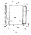
- FIG. 10 is a longitudinal sectional view of a cylindrical battery according to an embodiment of the present invention.
- the power generation element of the cylindrical battery includes a positive electrode 4 as a first electrode, a negative electrode 2 as a second electrode, a separator 6 interposed between the first electrode and the second electrode, and an electrolyte (not shown). It consists of The positive electrode 4 and the negative electrode 2 are wound through a separator 6 to form a wound electrode group.
- the battery case includes a bottomed cylindrical metal can 8 and a sealing member 12 that seals the opening of the metal can 8.
- the winding axis of the electrode group coincides with the central axis of the metal can 8, and the vicinity of the winding axis is a hollow portion 18 (diameter R) where no power generation element exists.
- the core 50 is preferably selected so that the diameter of the hollow part of the electrode group is 3 mm or less, preferably less than 1.5 mm. The core may be left in the battery without being removed.
- the core 50 After winding the laminated body to form the electrode group, the core 50 is extracted. Therefore, a hollow having a diameter R is formed at the center of the electrode group. Thereafter, the electrode group is stored in the metal can 8. At this time, the first end face from which the negative electrode current collecting lead 22 and the positive electrode current collecting lead 24 protrude is disposed on the opening side of the metal can 8.
- One end of the negative electrode current collector lead 22 is electrically connected to the exposed portion (second uncoated portion (A) 20a) of the negative electrode current collector sheet of the negative electrode 2.
- the other end of the negative electrode current collector lead 22 is connected to a connection position (welding point) 26 on the inner surface of the side wall near the opening of the metal can 8.
- the metal can 8 also serves as the negative electrode terminal 10.
- the connection between the negative electrode current collector lead 22 and the connection position 26 is performed by spot welding, for example.
- the insulating ring-shaped intermediate member 28 is disposed on the electrode group, and one end of the positive electrode current collecting lead 24 is joined to the lower surface of the conductive sealing member 12 by welding.
- the sealing member 12 also serves as the positive electrode terminal 14.
- an electrolyte is injected into the metal can 8 by a reduced pressure method.
- a cylindrical battery is obtained by crimping the opening end of the metal can 8 to the sealing member 12 via an insulating member (gasket) 16.
- An insulating ring member 30 is disposed on the periphery of the sealing member 12 exposed to the outside from the metal can 8, and insulation between the metal can 8 and the sealing member 12 is ensured.
- the edge surface of the first uncoated portion 40 a of the positive electrode current collector sheet 40 is more than the edge surface of the negative electrode current collector sheet 20. It protrudes to the opening side.
- the first uncoated portion 40 a of the positive electrode current collector sheet 40 is almost entirely covered with the insulating layer 5 including the edge surface. Accordingly, contact between the first uncoated portion 40a and, for example, the negative electrode current collector lead 22 is suppressed. Further, by causing the edge surface of the separator 6 to protrude toward the opening side of the metal can 8 with respect to the edge surface of the first uncoated portion 40a, the probability of an internal short circuit is further reduced.
- an insulating microporous thin film, a woven fabric or a non-woven fabric is used as the separator 6 interposed between the positive electrode 4 and the negative electrode 2.
- a material for the separator of the lithium ion battery for example, polyolefin such as polypropylene and polyethylene is preferably used. This is because polyolefin is excellent in durability and has a shutdown function.
- the thickness of the separator 6 is, for example, 10 ⁇ m to 300 ⁇ m, preferably 10 ⁇ m to 40 ⁇ m, and more preferably 10 ⁇ m to 25 ⁇ m.
- the microporous thin film may be a single layer film or a multilayer film.
- the separator has a porosity of preferably 30% to 70%, more preferably 35% to 60%.
- Nonaqueous electrolyte The non-aqueous electrolyte may be in a liquid, gel, or solid state.
- a liquid non-aqueous electrolyte used for a lithium ion battery is usually composed of a lithium salt and a non-aqueous solvent in which the lithium salt is dissolved.
- strand-shaped carbonate ester, cyclic carboxylic acid ester etc. are used.
- the cyclic carbonate include propylene carbonate and ethylene carbonate.
- the chain carbonate include diethyl carbonate, ethyl methyl carbonate, and dimethyl carbonate.
- Examples of the cyclic carboxylic acid ester include ⁇ -butyric lactone and ⁇ -valerolactone.
- the lithium salt for example, LiPF6, LiBF4 or the like is used.
- the above embodiment is merely an example of the present invention, and the present invention is not limited to the above embodiment.
- the present invention is preferably applied to various wound non-aqueous electrolyte batteries represented by lithium ion batteries.
- the battery may be a primary battery or a secondary battery.
- the shape of the battery may be cylindrical, and may be cylindrical or elliptical.
- the size of the battery is not limited. However, the technical significance of applying the present invention is increased when the metal can is a cylindrical shape having a diameter of 10 mm or less, more preferably 6 mm or less, and particularly 4.5 mm or less.
- the present invention can be applied to a wound battery, and is particularly useful for obtaining a small and high capacity cylindrical battery.
Abstract
Description
図1に示すように、正極4は、第1集電体シートである正極集電体シート40と、正極集電体シート40の両面に形成された正極活物質層41とを具備する。正極集電体シート40は矩形であり、本実施形態の場合、長辺方向(図1のY方向)が捲回軸方向(第1方向)に一致する。第1方向おける一端部(以下、第1端部)には、正極集電体シート40が露出している第1未塗工部40aが設けられている。第1端部は、電極群の第1端面側に配される。第1未塗工部40aは、第1端部に沿って帯状に設けられる。第1未塗工部40aには、短冊状の正極集電リード24の一端部が溶接により接続されている。 (Positive electrode)
As shown in FIG. 1, the
図7に示すように、負極2は、第2集電体シートである負極集電体シート20と、負極集電体シート20の両面に形成された負極活物質層21とを具備する。矢印Abの右側(Out)が電極群の最外周に配される捲き終わり側である。矢印Abの左側(In)は、電極群の中心側(捲き始め側)である。負極集電体シート20は、第2方向の長さが正極集電体シート40よりも大きく設定された矩形である。負極集電体シート20の第2方向(図7のX方向)における一端部(以下、第1端部)には、負極集電体シートが露出している第2未塗工部(A)20aが比較的幅広に設けられている。第2未塗工部(A)20aは、当該第1端部に沿って帯状に設けられる。第2未塗工部(A)20aには、短冊状の負極集電リード22の一端部が溶接により接続されている。 (Negative electrode)
As shown in FIG. 7, the
正極4と負極2との間に介在されるセパレータ6としては、絶縁性の微多孔薄膜、織布または不織布が用いられる。リチウムイオン電池のセパレータの材料としては、例えばポリプロピレン、ポリエチレンなどのポリオレフィンを用いることが好ましい。ポリオレフィンは耐久性に優れ、かつシャットダウン機能を有するためである。セパレータ6の厚さは、例えば10μm~300μmであり、10μm~40μmが好ましく、10μm~25μmがより好ましい。微多孔薄膜は、単層膜でもよく、多層膜でもよい。セパレータの空孔率は、30%~70%が好ましく、35%~60%が更に好ましい。 (Separator)
As the
非水電解質は、液体、ゲルまたは固体のいずれの状態でもよい。リチウムイオン電池に用いる液体の非水電解質は、通常、リチウム塩と、リチウム塩を溶解させる非水溶媒とで構成される。非水溶媒としては、特に限定されないが、環状炭酸エステル、鎖状炭酸エステル、環状カルボン酸エステルなどが用いられる。環状炭酸エステルとしては、プロピレンカーボネート、エチレンカーボネートなどが挙げられる。鎖状炭酸エステルとしては、ジエチルカーボネート、エチルメチルカーボネート、ジメチルカーボネートなどが挙げられる。環状カルボン酸エステルとしては、γ-ブチ口ラクトン、γ-バレロラクトンなどが挙げられる。リチウム塩としては、例えばLiPF6、LiBF4などが用いられる。 (Nonaqueous electrolyte)
The non-aqueous electrolyte may be in a liquid, gel, or solid state. A liquid non-aqueous electrolyte used for a lithium ion battery is usually composed of a lithium salt and a non-aqueous solvent in which the lithium salt is dissolved. Although it does not specifically limit as a non-aqueous solvent, Cyclic carbonate ester, chain | strand-shaped carbonate ester, cyclic carboxylic acid ester etc. are used. Examples of the cyclic carbonate include propylene carbonate and ethylene carbonate. Examples of the chain carbonate include diethyl carbonate, ethyl methyl carbonate, and dimethyl carbonate. Examples of the cyclic carboxylic acid ester include γ-butyric lactone and γ-valerolactone. As the lithium salt, for example, LiPF6, LiBF4 or the like is used.
4 正極(第1電極)
5 絶縁層
6 セパレータ
8 金属缶
10 負極端子
12 封口部材
14 正極端子
16 絶縁部材
18 中空部分
20 負極集電体シート
20a 第2未塗工部(A)
20b 第2未塗工部(B)
21 負極活物質層
22 負極集電リード
24 正極集電リード
26 接続位置
28 中間部材
30 リング部材
40 正極集電体シート
41 正極活物質層
40a 第1未塗工部
50 巻芯
54 固定用絶縁テープ
70 捲き終わり部分
70a,70b,70c,70d 切り欠き(第1切り欠き)
80 捲き始め部分
80a 切り欠き(第2切り欠き) 2 Negative electrode (second electrode)
4 Positive electrode (first electrode)
5 Insulating
20b Second uncoated part (B)
21 Negative electrode
80
Claims (11)
- 発電要素と、
前記発電要素を収容する電池ケースと、を具備し、
前記発電要素は、第1電極と、前記第1電極とは極性が異なる第2電極と、前記第1電極と前記第2電極との間に介在するセパレータと、電解質と、を具備し、前記第1電極と前記第2電極とが前記セパレータを介して捲回されて、第1端面およびその反対側の第2端面を有する電極群を形成しており、
前記第1電極は、第1集電体シートと、前記第1集電体シートの表面に形成された第1活物質層と、を具備し、前記第1電極には、第1集電リードが接続されており、
前記第2電極は、第2集電体シートと、前記第2集電体シートの表面に形成された第2活物質層と、を具備し、前記第2電極には、第2集電リードが接続されており、
前記第1電極の前記第1端面に配される端部および前記第1電極の前記第2端面に配される端部の少なくとも一方は、前記電極群の最外周に配置される捲き終わり部分が切り欠かれている、捲回型電池。 Power generation elements,
A battery case containing the power generation element,
The power generating element includes a first electrode, a second electrode having a polarity different from that of the first electrode, a separator interposed between the first electrode and the second electrode, and an electrolyte. The first electrode and the second electrode are wound through the separator to form an electrode group having a first end face and a second end face opposite to the first end face;
The first electrode includes a first current collector sheet and a first active material layer formed on a surface of the first current collector sheet. The first electrode includes a first current collector lead. Is connected,
The second electrode includes a second current collector sheet and a second active material layer formed on a surface of the second current collector sheet, and the second electrode includes a second current collector lead. Is connected,
At least one of the end portion disposed on the first end surface of the first electrode and the end portion disposed on the second end surface of the first electrode has a winding end portion disposed on the outermost periphery of the electrode group. A wound battery with a notch. - 前記電池ケースは、
有底筒状の金属缶と、
前記金属缶の開口を塞ぐ封口部材と、を具備し、
前記第1集電リードは、前記封口部材に電気的に接続されており、
前記第2集電リードは、前記金属ケースの内面に電気的に接続されている、請求項1に記載の捲回型電池。 The battery case is
A bottomed cylindrical metal can,
A sealing member for closing the opening of the metal can,
The first current collecting lead is electrically connected to the sealing member;
The wound battery according to claim 1, wherein the second current collecting lead is electrically connected to an inner surface of the metal case. - 前記端面側から見た前記切り欠きの長さが、前記第1電極の前記最外周に配置される部分の長さの1%以上、100%以下である、請求項1または2に記載の捲回型電池。 The scissors according to claim 1 or 2, wherein a length of the notch as viewed from the end face side is 1% or more and 100% or less of a length of the portion arranged on the outermost periphery of the first electrode. Revolving battery.
- 前記切り欠きの形状が、矩形である、請求項1~3のいずれか1項に記載の捲回型電池。 The wound battery according to any one of claims 1 to 3, wherein the shape of the notch is a rectangle.
- 前記第1端面は、前記開口側に配置されており、
前記第1集電リードは、前記第1端面から前記開口側に向かって延在している、請求項2~4のいずれか1項に記載の捲回型電池。 The first end surface is disposed on the opening side,
The wound battery according to any one of claims 2 to 4, wherein the first current collecting lead extends from the first end face toward the opening. - 前記第1集電体シートは、前記電極群の前記第1端面に配される端部に、両方の表面に前記第1活物質層を有さない第1未塗工部を有し、
前記第1集電リードは、前記第1未塗工部に接続されており、
前記第1未塗工部の前記捲き終わり部分が、切り欠かれている、請求項5に記載の捲回型電池。 The first current collector sheet has a first uncoated portion that does not have the first active material layer on both surfaces at an end portion disposed on the first end surface of the electrode group,
The first current collecting lead is connected to the first uncoated part,
The wound battery according to claim 5, wherein the end portion of the first uncoated portion is notched. - 前記第1未塗工部のエッジ面を覆うとともに、前記切り欠きを内包するように、前記第1未塗工部の両側の表面を覆う絶縁層が形成されている、請求項6に記載の捲回型電池。 The insulating layer which covers the surface of the both sides of the said 1st uncoated part is formed so that the edge surface of the said 1st uncoated part may be covered, and the said notch may be included. Winding battery.
- 前記絶縁層が、前記第1未塗工部の前記エッジ面から張り出している、請求項7に記載の捲回型電池。 The wound battery according to claim 7, wherein the insulating layer projects from the edge surface of the first uncoated portion.
- 前記第1端面において、前記セパレータの端部が、前記切り欠きの前記捲き終わり側の最端部よりも前記端面側に突出している、請求項8に記載の捲回型電池。 9. The wound battery according to claim 8, wherein, on the first end surface, an end portion of the separator protrudes toward the end surface side from an outermost end portion of the cutout on a side where the cutting ends.
- 前記電極群の捲回軸に対して垂直な方向における前記第2集電体シートの一端部に、少なくとも一方の表面に前記第2活物質層を有さない第2未塗工部を有し、
前記第2未塗工部に、前記第2集電リードが接続されており、
前記第2集電リードは、前記第1端面から前記開口側に向かって延在している、請求項5~9のいずれか1項に記載の捲回型電池。 At one end portion of the second current collector sheet in a direction perpendicular to the winding axis of the electrode group, a second uncoated portion not having the second active material layer on at least one surface is provided. ,
The second current collecting lead is connected to the second uncoated portion,
The wound battery according to any one of claims 5 to 9, wherein the second current collecting lead extends from the first end face toward the opening. - 前記電池ケースは、外径10mm以下の円筒型である、請求項1~10のいずれか1項に記載の捲回型電池。 The wound battery according to any one of claims 1 to 10, wherein the battery case has a cylindrical shape with an outer diameter of 10 mm or less.
Priority Applications (3)
| Application Number | Priority Date | Filing Date | Title |
|---|---|---|---|
| JP2017528278A JP6857872B2 (en) | 2015-07-10 | 2016-06-20 | Revolving battery |
| US15/573,566 US10615426B2 (en) | 2015-07-10 | 2016-06-20 | Wound battery including notched current collector sheet |
| CN201680033832.0A CN107735897B (en) | 2015-07-10 | 2016-06-20 | Winding type battery |
Applications Claiming Priority (2)
| Application Number | Priority Date | Filing Date | Title |
|---|---|---|---|
| JP2015-138746 | 2015-07-10 | ||
| JP2015138746 | 2015-07-10 |
Publications (1)
| Publication Number | Publication Date |
|---|---|
| WO2017010046A1 true WO2017010046A1 (en) | 2017-01-19 |
Family
ID=57756888
Family Applications (1)
| Application Number | Title | Priority Date | Filing Date |
|---|---|---|---|
| PCT/JP2016/002942 WO2017010046A1 (en) | 2015-07-10 | 2016-06-20 | Wound type battery |
Country Status (4)
| Country | Link |
|---|---|
| US (1) | US10615426B2 (en) |
| JP (1) | JP6857872B2 (en) |
| CN (1) | CN107735897B (en) |
| WO (1) | WO2017010046A1 (en) |
Cited By (6)
| Publication number | Priority date | Publication date | Assignee | Title |
|---|---|---|---|---|
| WO2019098023A1 (en) * | 2017-11-16 | 2019-05-23 | パナソニックIpマネジメント株式会社 | Cylindrical secondary battery |
| WO2019230298A1 (en) * | 2018-05-30 | 2019-12-05 | パナソニックIpマネジメント株式会社 | Nonaqueous electrolyte secondary battery |
| WO2019230297A1 (en) * | 2018-05-30 | 2019-12-05 | パナソニックIpマネジメント株式会社 | Nonaqueous electrolyte secondary battery |
| US20200313241A1 (en) * | 2017-09-29 | 2020-10-01 | Panasonic Intellectual Property Management Co., Ltd. | Cylindrical secondary battery |
| US20210280919A1 (en) * | 2018-07-30 | 2021-09-09 | Panasonic Intellectual Property Management Co., Ltd. | Lithium secondary battery |
| JP7463333B2 (en) | 2021-11-17 | 2024-04-08 | プライムプラネットエナジー&ソリューションズ株式会社 | battery |
Families Citing this family (2)
| Publication number | Priority date | Publication date | Assignee | Title |
|---|---|---|---|---|
| CN110199410B (en) * | 2017-01-24 | 2022-09-27 | 三洋电机株式会社 | Method for manufacturing electrode plate for battery, method for manufacturing battery, and battery |
| KR102582586B1 (en) | 2018-05-16 | 2023-09-25 | 삼성전자주식회사 | Electronic device including battery having a notch formed on at least a part of the uncoated area |
Citations (6)
| Publication number | Priority date | Publication date | Assignee | Title |
|---|---|---|---|---|
| JPH06260172A (en) * | 1993-03-02 | 1994-09-16 | Japan Storage Battery Co Ltd | Square form lithium battery |
| JP2001345115A (en) * | 2000-06-01 | 2001-12-14 | Mitsubishi Electric Corp | Battery |
| JP2004303590A (en) * | 2003-03-31 | 2004-10-28 | Sanyo Electric Co Ltd | Laminated battery, and manufacturing method of the same |
| JP2006278142A (en) * | 2005-03-29 | 2006-10-12 | Sanyo Electric Co Ltd | Square battery with spiral electrode |
| JP2008251256A (en) * | 2007-03-29 | 2008-10-16 | Toshiba Corp | Nonaqueous electrolyte battery, battery pack, and automobile |
| JP2012079501A (en) * | 2010-09-30 | 2012-04-19 | Gs Yuasa Corp | Battery |
Family Cites Families (11)
| Publication number | Priority date | Publication date | Assignee | Title |
|---|---|---|---|---|
| US6300002B1 (en) | 1999-05-13 | 2001-10-09 | Moltech Power Systems, Inc. | Notched electrode and method of making same |
| JP4649993B2 (en) * | 2005-01-12 | 2011-03-16 | パナソニック株式会社 | Lithium secondary battery and manufacturing method thereof |
| JP5127271B2 (en) * | 2007-03-12 | 2013-01-23 | 株式会社東芝 | Winding electrode battery and manufacturing method thereof |
| CN101807725A (en) * | 2009-02-18 | 2010-08-18 | 东莞新能源科技有限公司 | Lithium ion battery |
| EP2525434A1 (en) * | 2010-01-13 | 2012-11-21 | Panasonic Corporation | Lithium ion secondary battery and production method for same |
| JP5630859B2 (en) * | 2010-08-06 | 2014-11-26 | Fdkトワイセル株式会社 | Cylindrical storage battery |
| WO2012111061A1 (en) * | 2011-02-16 | 2012-08-23 | パナソニック株式会社 | Battery and method for manufacturing battery |
| KR101476963B1 (en) | 2012-03-30 | 2014-12-24 | 파나소닉 주식회사 | Cylindrical battery |
| JP2014071987A (en) | 2012-09-28 | 2014-04-21 | Panasonic Corp | Cylindrical lithium-ion secondary battery |
| US9666903B2 (en) | 2013-03-01 | 2017-05-30 | Panasonic Intellectual Property Management Co., Ltd. | Lithium ion secondary battery |
| US11476494B2 (en) * | 2013-08-16 | 2022-10-18 | Zenlabs Energy, Inc. | Lithium ion batteries with high capacity anode active material and good cycling for consumer electronics |
-
2016
- 2016-06-20 US US15/573,566 patent/US10615426B2/en active Active
- 2016-06-20 JP JP2017528278A patent/JP6857872B2/en active Active
- 2016-06-20 WO PCT/JP2016/002942 patent/WO2017010046A1/en active Application Filing
- 2016-06-20 CN CN201680033832.0A patent/CN107735897B/en active Active
Patent Citations (6)
| Publication number | Priority date | Publication date | Assignee | Title |
|---|---|---|---|---|
| JPH06260172A (en) * | 1993-03-02 | 1994-09-16 | Japan Storage Battery Co Ltd | Square form lithium battery |
| JP2001345115A (en) * | 2000-06-01 | 2001-12-14 | Mitsubishi Electric Corp | Battery |
| JP2004303590A (en) * | 2003-03-31 | 2004-10-28 | Sanyo Electric Co Ltd | Laminated battery, and manufacturing method of the same |
| JP2006278142A (en) * | 2005-03-29 | 2006-10-12 | Sanyo Electric Co Ltd | Square battery with spiral electrode |
| JP2008251256A (en) * | 2007-03-29 | 2008-10-16 | Toshiba Corp | Nonaqueous electrolyte battery, battery pack, and automobile |
| JP2012079501A (en) * | 2010-09-30 | 2012-04-19 | Gs Yuasa Corp | Battery |
Cited By (8)
| Publication number | Priority date | Publication date | Assignee | Title |
|---|---|---|---|---|
| US20200313241A1 (en) * | 2017-09-29 | 2020-10-01 | Panasonic Intellectual Property Management Co., Ltd. | Cylindrical secondary battery |
| WO2019098023A1 (en) * | 2017-11-16 | 2019-05-23 | パナソニックIpマネジメント株式会社 | Cylindrical secondary battery |
| JPWO2019098023A1 (en) * | 2017-11-16 | 2020-11-19 | パナソニックIpマネジメント株式会社 | Cylindrical secondary battery |
| WO2019230298A1 (en) * | 2018-05-30 | 2019-12-05 | パナソニックIpマネジメント株式会社 | Nonaqueous electrolyte secondary battery |
| WO2019230297A1 (en) * | 2018-05-30 | 2019-12-05 | パナソニックIpマネジメント株式会社 | Nonaqueous electrolyte secondary battery |
| JP7386432B2 (en) | 2018-05-30 | 2023-11-27 | パナソニックIpマネジメント株式会社 | Non-aqueous electrolyte secondary battery |
| US20210280919A1 (en) * | 2018-07-30 | 2021-09-09 | Panasonic Intellectual Property Management Co., Ltd. | Lithium secondary battery |
| JP7463333B2 (en) | 2021-11-17 | 2024-04-08 | プライムプラネットエナジー&ソリューションズ株式会社 | battery |
Also Published As
| Publication number | Publication date |
|---|---|
| JPWO2017010046A1 (en) | 2018-04-19 |
| US10615426B2 (en) | 2020-04-07 |
| US20180131009A1 (en) | 2018-05-10 |
| JP6857872B2 (en) | 2021-04-14 |
| CN107735897B (en) | 2020-11-03 |
| CN107735897A (en) | 2018-02-23 |
Similar Documents
| Publication | Publication Date | Title |
|---|---|---|
| US11183740B2 (en) | Rolled-type battery | |
| WO2017010046A1 (en) | Wound type battery | |
| JP6505859B2 (en) | Nonaqueous electrolyte secondary battery | |
| JP6948628B2 (en) | Revolving battery | |
| JP6775170B2 (en) | Revolving battery | |
| CN107851768B (en) | Method for manufacturing electrochemical device | |
| KR100515833B1 (en) | Jelly-roll type electrode assembly and secondary battery applying the same | |
| US20190221824A1 (en) | Non-aqueous electrolyte secondary battery | |
| JP2017069207A (en) | Lithium ion secondary battery and manufacturing method for the same | |
| WO2018124152A1 (en) | Coin-type battery and manufacturing method thereof | |
| KR20010098695A (en) | Sealed battery and method for manufacturing the same | |
| WO2013047515A1 (en) | Non-aqueous electrolyte secondary battery | |
| CN109891640B (en) | Electrode for nonaqueous electrolyte secondary battery and nonaqueous electrolyte secondary battery | |
| WO2012105553A1 (en) | Cylindrical secondary battery | |
| JP2014082055A (en) | Cylindrical power storage element | |
| JP2018055904A (en) | Electrochemical cell and manufacturing method of the electrochemical cell | |
| JP2017139085A (en) | Sealed battery | |
| JP6670086B2 (en) | Sealed battery | |
| JP2018200822A (en) | Laminate type battery | |
| JP2006147185A (en) | Wound electrode, its manufacturing method, and battery using it | |
| US11552374B2 (en) | Electrode for non-aqueous electrolyte secondary battery and non-aqueous electrolyte secondary battery | |
| JP2018139187A (en) | Wound type battery | |
| JP7022909B2 (en) | Revolving battery |
Legal Events
| Date | Code | Title | Description |
|---|---|---|---|
| 121 | Ep: the epo has been informed by wipo that ep was designated in this application |
Ref document number: 16824032 Country of ref document: EP Kind code of ref document: A1 |
|
| ENP | Entry into the national phase |
Ref document number: 2017528278 Country of ref document: JP Kind code of ref document: A |
|
| WWE | Wipo information: entry into national phase |
Ref document number: 15573566 Country of ref document: US |
|
| NENP | Non-entry into the national phase |
Ref country code: DE |
|
| 122 | Ep: pct application non-entry in european phase |
Ref document number: 16824032 Country of ref document: EP Kind code of ref document: A1 |