JP4705259B2 - Road information processing apparatus, method, road information processing software, navigation system and method, and road information database creation method - Google Patents
Road information processing apparatus, method, road information processing software, navigation system and method, and road information database creation method Download PDFInfo
- Publication number
- JP4705259B2 JP4705259B2 JP2001091297A JP2001091297A JP4705259B2 JP 4705259 B2 JP4705259 B2 JP 4705259B2 JP 2001091297 A JP2001091297 A JP 2001091297A JP 2001091297 A JP2001091297 A JP 2001091297A JP 4705259 B2 JP4705259 B2 JP 4705259B2
- Authority
- JP
- Japan
- Prior art keywords
- road
- road information
- vehicle
- vehicles
- shape
- Prior art date
- Legal status (The legal status is an assumption and is not a legal conclusion. Google has not performed a legal analysis and makes no representation as to the accuracy of the status listed.)
- Expired - Fee Related
Links
Images


Landscapes
- Instructional Devices (AREA)
- Navigation (AREA)
- Traffic Control Systems (AREA)
- Position Fixing By Use Of Radio Waves (AREA)
Description
【0001】
【発明の属する技術分野】
本発明は、ナビゲーションに関する技術の改良に関するもので、特に、具体的道路状況に関する高精度な情報を広範囲にわたりリアルタイムに低コストで取得するようにしたものである。
【0002】
【従来の技術】
近年、自動車の普及やコンピュータ技術の進展に伴い、自動車などの車両に搭載され目的地までの最適な経路を案内するナビゲーションシステムが急速に普及しつつある。ナビゲーションシステムは、指定された目的地への最適な経路をCD−ROMなどに記録された道路の情報から設定し、GPS(Global Positioning System)やジャイロなどで自車位置をリアルタイムに判断しながら、右左折点などを地図表示や音声で案内するものである。
【0003】
最近では、よりきめ細かな案内を行うため、道路幅など場所ごとの具体的道路状況を利用する例も知られている。例えば、特開平10−86761(車両用情報提供装置)では、ナビゲーションECU(Electric Control Unit)に、DGPS(Differential Global Positioning System)装置、地図データベースが接続される。
【0004】
また、この地図データベースには、全国の道路情報などを含む地図情報が記憶され、特に、道路の幅についての情報、すなわち道路の幅員、車線数路肩の広さ等の道路構成についてのデータが記憶されている。このような構成によると、ナビゲーションにおいて道路の幅員や車線数路肩の広さを用いることができる。
【0005】
また、例えば特開平11−144185(自動運転制御誘導システム)では、車両前方に位置する障害物の存在を検出するレーザーレーダと、前方道路路面の形状や自車両と車線との位置関係を認識するための撮影手段であるCCD(Charge Coupled Device)カメラとが、車両の前部に設けられる。
【0006】
この従来例では、CCDカメラから得られる映像信号に基づいて、画像処理用ECUが、路面データ及び車線上自車位置データを出力する。また、全体計画ECUは、レーザーレーダによる車両前方の障害物の情報、及び路車間通信装置からの車両前方の所定距離内における路面状態等の道路情報または渋滞情報等の交通情報を元に、車線維持・車線変更といった走行指示を走行指示処理によって決定できる。このような構成によると、ナビゲーションにおいて車両前方の障害物の存在、前方道路路面の形状、自車両と車線との位置関係を用いることができる。
【0007】
【発明が解決しようとする課題】
しかしながら、上記のような従来技術では、駐車車両等具体的道路状況に関する高精度な情報を広範囲にわたり低コストで収集することは不可能という問題点があった。
【0008】
例えば、道路幅を利用したナビゲーションを行うために、利用する全ての道路の幅をあらかじめ地図データベースに記録しておく場合、このような詳細な地図データベースの調査及び作成は膨大な時間とコストを要するため、ナビゲーションで常に最新の情報を利用することは事実上困難であった。また、この場合、道路幅の情報は予め固定されているため、渋滞の車列や駐車車両など変化する障害物の情報に対応したナビゲーションは不可能であった。
【0009】
一方、CCDカメラやレーザレーダを用いる従来技術では、検出された前方の障害物データや画像に基づいて前方の道路幅を算出するが、このような手法では、道路幅方向の精度が低く、高度な信号処理を必要とするためコストが増大する問題があった。
【0010】
本発明は、上記のような従来技術の問題点を解決するために提案されたもので、その目的は、具体的道路状況に関する高精度な情報を広範囲にわたりリアルタイムに低コストで取得する情報処理技術、すなわち道路情報処理装置、方法及び道路情報処理用ソフトウェア、ナビゲーションシステム及び方法、並びに道路情報データベースの作成方法を提供することである。
【0011】
本発明の他の目的は、渋滞区間の回避など効果的なナビゲーションを実現する情報処理技術を提供することであり、具体的目的は、以下の構成、作用、効果にそれぞれ対応するものである。
【0012】
【課題を解決するための手段】
上記の目的を達成するため、請求項1の道路情報処理装置は、道路に関し少なくとも場所ごとの道路幅を含む道路情報を格納する手段と、道路を通行する自車両の側方の物体までの側方距離を計測する手段と、自車両の現在位置を検出する手段と、予め記憶された自車両の幅と、計測された前記側方距離と、検出された前記現在位置とに基づいて、道路の場所ごとの環境の形状を含む新たな道路情報を得る手段と、前記道路情報を、前記新たな道路情報に基づいて更新する手段と、前記側方距離の情報とその側方距離を検出した位置情報とを含む前記更新された道路情報を、車々間もしくは路車間の無線通信によって交換する手段と、を備えたことを特徴とする。
【0013】
請求項7の発明は、請求項1の発明を方法という見方から捉えたもので、道路に関し少なくとも場所ごとの道路幅を含む道路情報を予め用意し、道路を通行する自車両の側方の物体までの側方距離を計測する処理と、自車両の現在位置を検出する処理と、予め記憶された自車両の幅と、計測された前記側方距離と、検出された前記現在位置とに基づいて、道路の場所ごとの環境の形状を含む新たな道路情報を得る処理と、前記道路情報を、前記新たな道路情報に基づいて更新する処理と、前記側方距離の情報とその側方距離を検出した位置情報とを含む前記更新された道路情報を、車々間もしくは路車間の無線通信によって交換する処理と、を含むことを特徴とする。
【0014】
請求項17の道路情報処理用ソフトウェアは、請求項1,7の発明をコンピュータのソフトウェアという見方から捉えたもので、道路に関し少なくとも場所ごとの道路幅を含む道路情報を予め用意し、コンピュータを制御することにより、道路を通行する自車両の側方の物体までの側方距離を計測させ、自車両の現在位置を検出させ、道路に関し少なくとも場所ごとの道路幅を含む予め記憶された道路情報と、自車両の幅と、計測され車々間もしくは路車間の無線通信によって交換したものを含む前記側方距離と、検出された前記現在位置とに基づいて、道路の場所ごとの環境の形状を含む新たな道路情報を得させ、予め記憶された前記道路情報を作成された前記新たな道路情報に基づいて更新させることを特徴とする。
【0015】
これらの態様では、自車の左右について物体までの側方距離を計測し、自車両の位置情報、自車両幅との演算により、道路幅方向における自車両の位置や、渋滞車両や駐車車両などの障害物の配列や実際の道路形状といった環境の形状を含む新たな道路情報を計算し、道路情報を更新することができる。これにより、具体的道路状況に関する高精度な情報を広範囲にわたりリアルタイムに低コストで取得することが可能となり、効果的ナビゲーションにも利用可能となる。
【0016】
請求項2の発明は、請求項1記載の道路情報処理装置において、前記環境の形状について、前後の変化と大きさとに基づいて、道路形状と道路以外の形状とを判別して記録することを特徴とする。
【0017】
請求項8の発明は、請求項2の発明を方法という見方から捉えたもので、請求項7記載の道路情報処理方法において、前記環境の形状について、前後の変化と大きさとに基づいて、道路形状と道路以外の形状とを判別して記録することを特徴とする。
【0018】
請求項18の発明は、請求項2,8の発明を、コンピュータのソフトウェアという見方から捉えたもので、請求項17記載の道路情報処理用ソフトウェアにおいて、前記環境の形状について、前後の変化と大きさとに基づいて、道路形状と道路以外の形状とを判別して記録させることを特徴とする。
【0019】
これらの態様では、環境の形状について、幅の変化がなだらかか突然かといった変化と、車両の大きさの範囲内か否かとに基づいて、道路と、それ以外の車両や自動販売機等を判別して記録することにより、得られる道路情報を、渋滞区間の回避又は広い道の選択といった異なった目的に応じて利用することが容易になる。
【0020】
請求項3の発明は、請求項2記載の道路情報処理装置において、判別された前記道路以外の形状のうち、車両について予め決められた所定のサイズの範囲内か否かに基づいて、車両の形状と車両以外の形状を判別して記録し、判別された前記車両の配列を渋滞情報として記録することを特徴とする。
【0021】
請求項9の発明は、請求項2の発明を方法という見方から捉えたもので、請求項8記載の道路情報処理方法において、判別された前記道路以外の形状のうち、車両について予め決められた所定のサイズの範囲内か否かに基づいて、車両の形状と車両以外の形状を判別して記録し、判別された車両の配列を渋滞情報として記録することを特徴とする。
【0022】
これらの態様では、道路以外の形状について、長さや縦横比といった所定のサイズの範囲内か否かで車両とそれ以外を判別し、さらに、車両の配列は渋滞情報として記録することにより、渋滞しがちな道路区間や、自動販売機・看板・通行人などの多い道路区間といった区別が容易になり、よりきめ細かな効果的ナビゲーションが容易になる。
【0023】
請求項4の発明は、請求項1から3のいずれか1つに記載の道路情報処理装置において、前記道路情報を外部と送受信するための無線通信手段と、外部から受信した前記道路情報に基づいて自車両の道路情報を更新する手段と、を備えたことを特徴とする。
【0024】
請求項10の発明は、請求項4の発明を方法という見方から捉えたもので、請求項7から9のいずれか1つに記載の道路情報処理方法において、前記道路情報を無線通信により外部と送受信する処理と、外部から受信した前記道路情報に基づいて自車両の道路情報を更新する処理と、を含むことを特徴とする。
【0025】
これらの態様では、車両間や路車間・電波や赤外線といった外部との無線通信で道路情報を送受信することにより、各車両で道路情報をより一層有効活用することが可能となる。
【0026】
請求項5のナビゲーションシステムは、請求項1から4のいずれか1つに記載の道路情報処理装置を含み、前記側方距離の情報を含む前記道路情報を車々間の無線通信によって交換する手段と、交換した道路情報に基づいて目的地への経路案内を行う手段と、を備えたことを特徴とする。
【0027】
請求項11のナビゲーション方法は、請求項5の発明を方法という見方から捉えたもので、請求項7から10のいずれか1つに記載の道路情報処理方法と、前記側方距離の情報を含む前記道路情報を車々間の無線通信によって交換する処理と、交換した道路情報に基づいて目的地への経路案内を行う処理と、を含むことを特徴とする。
【0028】
これらの態様では、複数の車両間で道路情報を交換し利用することが可能となるので、これから向かう地域の情報を対向車から得るなど、より合理的なナビゲーションが可能となる。
【0029】
請求項6のナビゲーションシステムは、請求項1から4のいずれか1つに記載の道路情報処理装置を含み、前記側方距離の情報を含む前記道路情報を路車間の無線通信によって交換する手段と、交換した道路情報に基づいて目的地への経路案内を行う手段と、を備えたことを特徴とする。
【0030】
請求項12のナビゲーション方法は、請求項6の発明を方法という見方から捉えたもので、請求項7から10のいずれか1つに記載の道路情報処理方法を含み、前記側方距離の情報を含む前記道路情報を路車間の無線通信によって交換する処理と、交換した道路情報に基づいて目的地への経路案内を行う処理と、を含むことを特徴とする。
【0031】
これらの態様では、通信ネットワークやサーバとの路車間通信により、多数の車両間で広範囲に多量の道路情報を集積し利用することが可能となるので、より合理的なナビゲーションが可能となる。
【0032】
請求項13の発明は、請求項7から10のいずれか1つに記載の道路情報処理方法において、あらかじめ記録された各車両の車両幅と、各車両で測定した前記側方距離とを車両間で交換することにより、車両のすれ違いにおける余裕を予測することを特徴とする。
【0033】
この態様では、すれ違おうとする各車両の間で、自車の車両幅と測定した側方距離とを、互いに交換し、すれ違いにおける余裕を予測することにより、余裕の多い場所ですれ違ったり事故を防止するなど各車両の円滑な運行が容易になる。
【0034】
請求項14の発明は、請求項9,10又は13記載の道路情報処理方法において、各車両間で判別された前記車両の配列を交換し、各車両において複数の他車から提供された前記車両の各配列同士を照合することにより、共通の車両の配列を検出しその移動を追従することを特徴とする。
【0035】
この態様では、複数の他車で検出された車両長の配列同士を照合して共通部分を検出し、その移動を追従すなわち追跡することにより、他の道路区間における平均速度や渋滞状況を知ることができ、到着時間の正確な予想や渋滞区間回避など効果的なナビゲーションが可能となる。
【0036】
請求項15の発明は、請求項9,10,13又は14のいずれか1つに記載の道路情報処理方法において、どこにどのような駐車施設があるかの情報を各車両で予め用意し、各車両間で判別された前記車両の配列を交換し、前記駐車施設に該当する場所について他車両で判別された前記車両の配列とから、その駐車施設の空き状況を判断することを特徴とする。
【0037】
この態様では、パーキングメーターなどの駐車施設について、その場所を通ってきた他車から得られる道路情報に基づいて、空きスペースの数などの空き状況を前もって判断できるので、空きが無いときは最寄りの他の駐車施設を案内するなど効果的なナビゲーションが可能となる。
【0038】
請求項16の道路情報データベースの作成方法は、道路を通行する自車両の側方の物体までの側方距離を計測し、自車両の現在位置を検出し、道路に関し少なくとも場所ごとの道路幅を含む予め記憶された道路情報と、自車両の幅と、計測された前記側方距離と、検出された前記現在位置とに基づいて、道路の場所ごとの環境の形状を含む新たな道路情報を作成し、予め記憶された前記道路情報を、作成された新たな道路情報に基づいて更新し、この更新した新たな道路情報をそれぞれ前記リムーバブルメディアに記録し、前記各車両から前記リムーバブルメディアを収集し、記録された道路情報を前記各リムーバブルメディアから読み出して収集し、収集された道路情報に基づいて道路情報データベースを作成することを特徴とする。
【0039】
この態様では、各車両が検出した道路情報を、メモリカードなどの可搬情報記録媒体すなわちリムーバブルメディアに記録して収集し、収集された道路情報から詳細な道路情報データベースを低コストに作成し、各道路区間の実情に即した効果的なナビゲーションを行うことが可能となる。
【0040】
【発明の実施の形態】
次に、本発明の複数の実施の形態(以下「実施形態」と呼ぶ)について、添付の図を参照して具体的に説明する。なお、各実施形態は、本発明の道路情報処理装置を含むナビゲーションシステム(以下「本システム」と呼ぶ)と、本システム上で実行される道路情報処理方法及びナビゲーション方法に関するもので、典型的には、コンピュータのCPUや周辺装置をソフトウェアで制御することにより実現される。
【0041】
なお、この場合のハードウェアやソフトウェアの実現態様は各種変更可能であり、例えば上記のようなソフトウェアや、そのようなソフトウェアを記録した機械可読型記録媒体、例えばCD−ROM、フラッシュメモリ、ROMチップパッケージなども本発明の一態様である。このため、以下の説明では、本発明及び各実施形態の各機能に対応する仮想的回路ブロックを用いる。
【0042】
〔1.第1実施形態〕
〔1−1.第1実施形態の構成〕
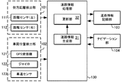
第1実施形態は、側方距離の検出に基づいて道路情報を更新する例であり、図1の機能ブロック図に示す次の構成要素を備えている。すなわち、側方距離検出部101は、道路を通行する自車両の側方の物体までの側方距離を計測すなわち検出する手段であり、複数の距離センサ111,112から構成される。ここで、距離センサ111は自車両の左側の、距離センサ112は、自車両の右側の側方距離をそれぞれ検出するように構成される。そして、側方距離検出部101は、車両の側面から側方の障害物までの距離を左右それぞれ検出し、得られた検出結果を表す側方距離情報を道路情報処理部130へ出力するように構成される。
【0043】
また、車両位置検出部102は、自車両の現在位置を検出する手段であり、GPS受信機121、ジャイロ122、車速センサ123などから構成され、得られた自車の現在位置を表す位置情報を道路情報処理部130へ出力するように構成される。
【0044】
また、道路情報記録部103は、道路に関し少なくとも場所ごとの道路幅を含む道路情報を格納する手段であり、あらかじめ記録された自車両の車両幅や道路情報を、道路情報処理部130からの要求に応じて道路情報処理部130へ出力するとともに、道路情報処理部130が出力する新たな道路情報を記録するように構成される。
【0045】
ここで、道路情報は、どこにどのような道路があるかを表す情報であり、例えば、交差点やカーブ地点などのノードを、距離を表すリンクで接続することによって表し、必要に応じてコンビニエンスストア、ガソリンスタンドなどの目標物(ランドマーク)を表す情報や、表示用の細かい道路情報などを伴う。また、本実施形態における道路情報には、道路幅を含む地図情報などの静的情報に加えて、道路の渋滞、駐車施設の混雑、障害物などの動的情報が含まれる。また、道路情報記録部103はその一部または全部を、メモリやディスクなどのリムーバブルメディアとすることも可能である。
【0046】
また、ナビゲーション部104は、地図や選択肢の表示や操作受付などを行うユーザインタフェース機能を備え、道路情報処理部130が出力する道路情報を用いてユーザに対するナビゲーションを行うとともに、ユーザの操作を道路情報処理部130へ出力するように構成される。また、道路情報処理部130は、側方距離検出部101が出力する側方距離情報、車両位置検出部102が出力する位置情報、道路情報記録部103が出力する道路情報を用いて得られる新たな道路情報を道路情報記録部103へ出力するように構成される。
【0047】
特に、道路情報処理部130は、図1に示す次の各構成要素を備えている。すなわち、道路情報生成部31は、予め記憶された自車両の幅と、計測された前記側方距離と、検出された前記現在位置とに基づいて、道路の場所ごとの環境の形状を含む新たな道路情報を生成する手段である。また、更新部32は、道路情報記録部103に記録されている道路情報を、得られた新たな道路情報に基づいて更新する手段である。
【0048】
また、道路情報処理部130は、前記環境の形状について、前後の変化と大きさとに基づいて、道路形状と道路以外の形状とを判別して記録するように構成されている。また、道路情報処理部130は、判別された前記道路以外の形状のうち、車両について予め決められた所定のサイズの範囲内か否かに基づいて、車両の形状と車両以外の形状を判別して記録し、判別された前記車両の配列を渋滞情報として記録するように構成されている。
【0049】
〔1−2.第1実施形態の作用〕
以上のように構成された第1実施形態は、次のように作用する。
〔1−2−1.側方距離の検出〕
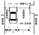
まず、側方距離検出の動作について詳細に説明する。ここで、図2に、第1実施形態において側方距離検出の動作の一例を示すための概念的平面図を示す。この例において、距離センサ111は自車両200の左側向き、距離センサ112は自車両200の右側向きで、自車両200のそれぞれの側面に設置されている。これら距離センサ111,112は、超音波、電波、光波などを送信し、障害物などの物体による反射波の受信を行うことにより、物体までの距離を測定する装置である。
【0050】
この例において、図1に示した側方距離検出部101は、距離センサ111により得られる自車両左端から左側の障害物201までの距離l(小文字L)と、距離センサ112により得られる自車両右端から右側の障害物202までの距離rを、道路情報処理部130へ出力する。また、道路情報記録部103は、あらかじめ記録されている自車両200固有の車両幅wを道路情報処理部130へ出力する。従って、道路情報処理部130は、道路幅(l+w+r)と道路幅方向における自車両の位置を含む側方距離情報を得ることができる。
【0051】
〔1−2−2.道路情報の生成と更新〕
次に、道路情報の生成と更新について詳細に詳細に説明する。すなわち、道路情報生成部31は、予め記憶された自車両の幅と、計測された前記側方距離と、検出された前記現在位置とに基づいて、道路の場所ごとの環境の形状を含む新たな道路情報を生成する。そして、更新部32は、道路情報記録部103に記録された道路情報を、得られた新たな道路情報に基づいて更新する処理を行う。
【0052】
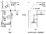
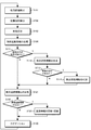
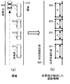
ここでは、図3に、第1実施形態における道路情報の生成と更新の例を示すための概念的平面図を示す。このうち図3(a)は自車両付近の環境、図3(b)は自車両が検出した道路情報を表す概念的平面図である。また、図4は、道路情報の生成と更新における処理手順を示すフローチャートである。
【0053】
ここで、図3(a)(b)に示す自車両300が、道路312上の走行経路311を走行する場合を考える。この場合、図1に示した側方距離検出部101は、上述した道路幅方向の距離測定314を逐次行い、検出した側方距離を道路情報処理部130へ出力する(ステップS101)。また、図1に示した車両位置検出部102は、検出した車両位置と時刻を対応させて得られる検出経路321を、道路情報処理部130へ出力する(S102)。そして、道路情報処理部130は、側方距離検出部101が出力する側方距離、車両位置検出部102が出力する検出経路321、道路情報記録部103が出力する地図とを対応させ、環境の形状を算出する(S103)。
【0054】
また、道路情報処理部130は、前記環境の形状について、前後の変化と大きさとに基づいて、道路形状と道路以外の形状とを判別して記録する。すなわち、道路情報処理部130は、幅や前後のつながりから道路形状と認識できる検出経路形状322を、静的な道路情報として登録する(S104)。また、道路形状と認識できない検出物体形状323が存在する場合は(S111)、動的な道路情報として登録する(S112)。具体的には、検出物体形状323について、物体の長さと車両長の範囲との比較などにより、車両形状があるか否かの認識を行い(S113)、車両と認識されれば、車両長などの検出車両情報を動的な道路情報に付加する(S114)。
【0055】
こうして得られた静的な道路情報と動的な道路情報が、道路情報記録部103に存在しない、または既に記録されている情報と異なる場合(S122)、静的な道路情報と動的な道路情報を更新し、道路情報記録部103へ出力する(S123)。また、ナビゲーション部104は、道路情報記録部103に記録された道路情報を用いてナビゲーションを行う(S130)。
〔1−2−3.車両認識の具体的動作〕
【0056】
また、第1実施形態における車両認識の動作について詳細に説明する。すなわち、道路情報生成部31は、判別された前記道路以外の形状のうち、車両について予め決められた所定のサイズの範囲内か否かに基づいて、車両の形状と車両以外の形状を判別して記録し、判別された車両の配列を渋滞情報として記録する。
【0057】
まず、図5に、車両認識の動作の一例を示すための概念的平面図を示す。このうち図5(a)は自車両付近の環境を示す。ここでは、自車両500が走行する道路510の反対車線に他車両511、512、513、514が走行する場合を考える。また、図5(b)は自車両500が検出した道路情報を示す。この例では、形状より道路と認識できる検出経路形状520の他、道路とは認識できない検出物体形状521、522、523、524が存在する。
【0058】
車両認識の基準としては、例えば、検出物体の縦横比が1.2:1〜3:1程度の所定範囲に収まっている場合に車両と認識することが考えられる。すなわち、検出物体形状521、522、523、524についてそのような基準に照らし、その大きさより車両の可能性があれば、検出した物体の長さd1、d2、d3、d4を車両長として認識し、並んだものを配列とする。この車両長配列を動的な道路情報として道路情報記録部103に記録し、渋滞情報として利用することができる。
【0059】
また、道路情報記録部103がリムーバブルメディアを含む場合、道路情報データベースの製作者は、各車両の使用者からリムーバブルメディアを受け取って各車両の道路情報を収集し、管理することにより、効率的に道路情報データベースを作成しユーザに提供することができる。具体的には、常時車両が列をなしているような道路区間は実質的に狭い道路や通過所要時間の多い道路とみなすなどが考えられる。
【0060】
すなわち、各車両にはリムーバブルメディアの読み書き手段を備え、各車両において、道路を通行する自車両の側方の物体までの側方距離を計測し、自車両の現在位置を検出し、予め記憶された自車両の幅と、計測された前記側方距離と、検出された前記現在位置とに基づいて、道路の場所ごとの環境の形状を含む新たな道路情報を作成し、新たな道路情報をそれぞれリムーバブルメディアに記録する。そして、前記製作者は、各車両からリムーバブルメディアを収集し、記録された道路情報を各リムーバブルメディアから読み出して収集し、収集された道路情報に基づいて道路情報データベースを作成する。
【0061】
〔1−3.第1実施形態の効果〕
以上説明したように、第1実施形態によれば、道路環境の最新の形状を検出し、ナビゲーションに利用することができる。特に、第1実施形態は、距離センサを用いることにより低コストで構成可能である。
【0062】
すなわち、まず、第1実施形態では、各車両において、自車の左右について物体までの側方距離を計測し、自車両の位置情報、自車両幅との演算により、道路幅方向における自車両の位置や、渋滞車両や駐車車両などの障害物の配列や実際の道路形状といった環境の形状を含む新たな道路情報を計算し、道路情報を更新することができる。これにより、具体的道路状況に関する高精度な情報を広範囲にわたりリアルタイムに低コストで取得することが可能となり、効果的ナビゲーションにも利用可能となる。
【0063】
また、第1実施形態では、環境の形状について、幅の変化がなだらかか突然かといった変化と、車両の大きさの範囲内か否かとに基づいて、道路と、それ以外の車両や自動販売機等を判別して記録することにより、得られる道路情報を、渋滞区間の回避又は広い道の選択といった異なった目的に応じて利用することが容易になる。
【0064】
また、第1実施形態では、道路以外の形状について、長さや縦横比といった所定のサイズの範囲内か否かで車両とそれ以外を判別し、さらに、車両の配列は渋滞情報として記録することにより、渋滞しがちな道路区間や、自動販売機・看板・通行人などの多い道路区間といった区別が容易になり、よりきめ細かな効果的ナビゲーションが容易になる。
【0065】
また、第1実施形態では、各車両が検出した道路情報を道路情報データベースの管理者が収集、管理することにより、最新の道路形状や渋滞情報を含む道路情報データベースを低コストで作成し、提供することができる。
【0066】
すなわち、第1実施形態では、各車両が検出した道路情報を、メモリカードなどの可搬情報記録媒体すなわちリムーバブルメディアに記録して収集し、収集された道路情報から詳細な道路情報データベースを低コストに作成し、各道路区間の実情に即した効果的なナビゲーションを行うことが可能となる。
【0067】
〔2.第2実施形態〕
第2実施形態は、通信機能により車々間通信を行う例である。
〔2−1.第2実施形態の構成〕
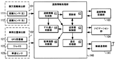
すなわち、第2実施形態は、図1に示した第1実施形態の構成に加え、図6の機能ブロック図に示すように、無線通信部141を備えている。なお、図6において、第1実施形態を示した図1における対象と同一又は相当する要素については、同じ符号をつけ、説明は省略する。
【0068】
すなわち、無線通信部141は、道路情報を外部と送受信するための無線通信手段であり、道路情報処理部140が出力する道路情報を外部へ送信するとともに、外部から受信した道路情報を道路情報処理部140へ出力する手段である。また、第2実施形態における道路情報処理部140は、第1実施形態における道路情報処理部130(図1)に準じて構成されるが、送受信制御部43を有し、この送受信制御部43は、道路情報記録部103が出力し側方距離情報を含む道路情報を無線通信部141へ出力したり、道路情報を車々間の無線通信によって他車と交換するように構成されている。
【0069】
また、道路情報処理部140の更新部42は、外部から受信した道路情報に基づいて自車両の道路情報を更新する手段でもあり、無線通信部141が出力する道路情報と道路情報記録部103が出力する道路情報の比較により、新たな道路情報を生成し道路情報記録部103へ出力するように構成される。
【0070】
また、道路情報処理部140は、前記のように交換した道路情報に基づいて、ナビゲーション部104と共に、目的地への経路案内を行うように構成されている。特に、道路情報処理部140のすれ違い判断部44は、あらかじめ記録された各車両の車両幅と、各車両で測定した側方距離とを車両間で交換することにより、車両のすれ違いにおける余裕を予測する処理を制御する部分である。また、追従処理部45は、車両間で判別された車両の配列を他車と交換するとともに、複数の他車から提供された車両の各配列同士を照合することにより、共通の車両の配列を検出しその移動を追従する処理を行う部分である。
【0071】
また、各車両の道路情報記録部103には、どこにどのような駐車施設があるかの情報が用意され、道路情報処理部140の駐車施設判断部46は、各車両間で判別された車両の配列を交換し、前記駐車施設の情報と、前記駐車施設に該当する場所について他車両で判別された車両の配列とから、その駐車施設の空き状況を判断する部分である。
【0072】
〔2−2.第2実施形態の作用〕
以上のように構成された第2実施形態では、道路情報を無線通信により外部と送受信する処理と、外部から受信した道路情報に基づいて自車両の道路情報を更新する処理と、が行われる。ここで、第2実施形態における処理手順を図7のフローチャートに示す。なお、この図7において、ステップS101からS123までの処理は、図4で同じ符号で示した各処理と同様である。
【0073】
すなわち、第2実施形態において、ステップS122またはS123までの道路情報検出の動作を終えると、送受信制御部43による制御に基づき、無線通信部141は他の車両に対する通信要求を行う(S201)。このとき、外部との通信が可能であれば(S202)、無線通信部141は、自車両の持つ道路情報と、外部の持つ道路情報の交換のための送受信を行う(S203)。
【0074】
また、道路情報処理部140は、受信した道路情報と自車両の持つ道路情報との比較を行い(S204)、受信した道路情報が、自車両の持つ道路情報に存在しない、または自車両の持つ道路情報に変化を与えるものであれば(S205)、新規の道路情報として処理を行う。
【0075】
例えば、道路情報処理部140のすれ違い判断部44は、新規の道路情報により自車両と他車両のすれ違いがあると判断した場合(S211)、後述するすれ違い余裕の算出を行い、ナビゲーションに利用する(S212)。また、道路情報処理部140は、受信した道路情報の中に、外部が検出した車両の車両長を含む検出車両情報があれば(S221)、後述する車両追従情報の生成を行う(S222)。
【0076】
そして、道路情報処理部140の更新部42は、これらの新規道路情報を道路情報記録部103に出力し、ナビゲーション部104は、道路情報記録部103に記録された道路情報を用いてナビゲーションを行う(S130)。
【0077】
〔2−2−1.車々間通信を用いたナビゲーションの例〕
次に、上記のような第2実施形態における車々間通信を用いたナビゲーションの概略を説明する。この例では、送受信制御部43と無線通信部141により、側方距離情報を含む道路情報を車々間の無線通信によって交換し、ナビゲーション部104及び道路情報処理部140が、交換した道路情報に基づいて目的地への経路案内を行う。
【0078】
まず、図8に、車々間通信を用いたナビゲーションを説明するための概念的平面図を示す。この場合、ナビゲーションシステムは、例えば、複数の車両400、410、420、430に搭載された道路情報処理装置やナビゲーションシステムを含む複合システムとして把握することができる。
【0079】
〔2−2−2.道路情報の獲得と交換〕
ここでは、自車両400が、道路440上の自車両経路401を走行する場合を例に挙げる。まず、自車両400、第1他車両410、第2他車両420、第3他車両430は上述した道路情報処理装置を搭載し、走行した経路に関する環境の形状や車両の存在を含む道路情報を得る。
【0080】
すなわち、第1他車両410は走行した第1他車両経路411周辺の道路情報、第2他車両420は走行した第2他車両経路421周辺の道路情報、第3他車両430は走行した第3他車両経路431周辺の道路情報を、それぞれ得る。そして、自車両400が自車両経路401を走行し、第1他車両410、第2他車両420、第3他車両430と接近するたびに、互いに接近した車両同士の間で、無線通信部141を用いた車々間通信を行い、互いの道路情報を交換する。
【0081】
従って、自車両400は、自車両経路401、第1他車両経路411、第2他車両経路421、第3他車両経路431に関して、環境の形状や車両の存在を含む詳細な道路情報が得られる。また、自車両400より前方のリアルタイムな道路情報を得ることにより、これから走行する経路に関する判断に利用することができる。また、本実施の形態におけるナビゲーションシステムを搭載した車両の情報だけでなく、各車両の経路上の車両を検出できることから、本実施の形態におけるナビゲーションシステムを搭載していない車両の情報も検出できる。
【0082】
〔2−2−3.すれ違い認識の動作〕
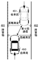
次に、車々間通信を用いたナビゲーションシステムにおけるすれ違い認識の動作について詳細に説明する。この処理では、あらかじめ記録された各車両の車両幅と、各車両で測定した前記側方距離とを車両間で交換することにより、車両のすれ違いにおける余裕を予測する。ここで、図9は、すれ違い認識の動作の一例を説明するための概念的平面図であり、塀などの障害物461、462が存在し道路幅の狭い道路において、自車両450に対して他車両451が対向して接近してくる場合を考える。
【0083】
この場合、自車両450および他車両451は、上述した道路情報検出を継続的に行っており、接近したときには車々間通信を行う。すなわち、他車両451は、他車両451の車両幅および他車両451が検出した側方距離を自車両450に送信する。そして、自車両450の無線通信部141は、他車両451が送信した情報を受信し、自車両450の道路情報処理部140は、自車両450の車両幅、他車両451の車両幅、側方距離に基づいて、車両のすれ違いの余裕を算出し、ナビゲーション部104を介して運転者に通知する。
【0084】
〔2−2−4.車両追従の動作〕
次に、車々間通信を用いたナビゲーションシステムにおける車両追従の動作について詳細に説明する。この処理では、各車両間で判別された車両の配列を交換し、各車両において複数の他車から提供された車両の各配列同士を照合することにより、共通の車両の配列を検出しその移動を追従する。すなわち、図5に例示したように車両認識を行った車両は、車両長配列を付近の他車両へ送信する。そして、複数の送信元から車両長配列を受信した他車両の道路情報処理部103は、以前に受信した車両長配列と新しく受信した車両長配列とを比較する。
【0085】
このような比較の結果、複数の車両長配列の間で要素が一致するか、又はある割合の要素が一致する場合、複数の車両長配列は同一車両を含むと判断する。そして、複数の受信した情報の位置と時間を関連づけることにより車両追従を行う。すなわち、同一車両を検出した位置と時間から、車両の移動距離と移動時間を求め、渋滞の程度や長さ、予測通過所要時間といった渋滞情報の判断に利用することができる。このように、本実施の形態におけるナビゲーションシステムを搭載していない車両の情報についても、移動距離と移動時間を得ることができる。
【0086】
〔2−2−5.経路認識〕
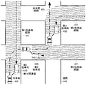
次に、車々間通信を用いたナビゲーションシステムにおける経路認識の動作について説明する。この処理では、自車が選択可能な経路が複数ある場合、他車から得られる道路情報に基づいて各経路の状況を判断(認識)し、自車にとって適切な経路を選択する。まず、図10に、経路認識の動作の一例を説明するための概念的平面図を示す。
【0087】
このうち図10(a)は、自車両600がとりうる2つの候補経路を表す。すなわち、自車両600が目的地まで走行しようとする道路601には、第1候補経路610と第2候補経路620が存在する。ここで、第1候補経路610の途中には渋滞車両604、605、606が存在し、第2候補経路620の途中には幅員減少区間607が存在する場合を考える。
【0088】
また、図10(b)は、第1候補経路610に関して第1他車両611が検出した道路情報を表す。すなわち、本システムを搭載し自車両600とすれ違う第1他車両611は、自車両600が向かおうとする第1候補経路610を、自車両600と逆の方向に走行してきたとする。この場合、自車両600とすれ違うまでに第1他車両611は、上述した道路情報検出により、静的な道路情報である第1検出経路形状613を得る。さらに第1他車両611は、検出物体形状614、615、616を得ることにより、車両604、605、606の車両長を含む動的な道路情報を得る。
【0089】
そして、自車両600と第1他車両611が接近した時点で、自車両600と第1他車両611は車々間通信を行う。その結果、自車両600は、第1候補経路610上に多数の渋滞車両604、605、606が存在することを認識し、その情報を第1候補経路610の走行時間の予測に利用することができる。
【0090】
また、図10(c)は、第2候補経路620に関して第2他車両621が検出した道路情報を表す。ここで、第1他車両611と同様、本システムを搭載し自車両600とすれ違う第2他車両621は、自車両600が向かおうとする第2候補経路620を、自車両600と逆の方向に走行してきたとする。この場合、自車両600とすれ違うまでに第2他車両621は、上述した道路情報検出により、静的な道路情報である第2検出経路形状623を得る。
【0091】
そして、自車両600と第2他車両621が接近した時点で、自車両600と第2他車両621は車々間通信を行う。その結果、自車両600は、第2候補経路620上に幅員減少区間607が存在することを認識し、その情報をすれ違いの危険性の予測に利用することができる。
【0092】
次に、道路情報処理部140は、ユーザがナビゲーション部104に入力した経路選択の条件に基づいて、第1候補経路610と第2候補経路620を比較する。すなわち、ユーザがすれ違いの危険性を避けたいと考えていれば第1候補経路610を選択し、ユーザが渋滞を避けたいと考えていれば第2候補経路620を選択する。そして、ナビゲーション部104は、選択された候補経路に従って、ユーザに対するナビゲーションを行う。ここで、経路選択の条件は、ユーザの入力に限らず、許容できる渋滞や危険性に関してあらかじめ設定した基準を用いても良い。
【0093】
〔2−2−6.駐車施設の認識〕
次に、車々間通信を用いたナビゲーションシステムにおける駐車施設認識の動作について説明する。これは、どこにどのような駐車施設があるかの情報を各車両で予め用意し、各車両間で判別された前記車両の配列を交換し、前記駐車施設の情報と、前記駐車施設に該当する場所について他車両で判別された前記車両の配列とから、その駐車施設の空き状況を判断するものである。
【0094】
まず、図11に、駐車施設認識の動作の一例を説明するための概念的平面図を示す。ここで、自車両700が駐車施設711、712、713に向かっており、運転者が駐車施設における空きスペースの数を知りたい場合を考える。この場合、駐車施設として、駐車車両を検出しやすいパーキングメータの場合を例に挙げる。
まず、図11(a)は自車両700が向かおうとする駐車施設付近の環境を表す。すなわち、自車両700が向かおうとする道路710にはパーキングメータによる3カ所の駐車スペース711、712、713が設置されており、そのうち2カ所は駐車車両が存在する駐車済みスペース711、713、1カ所は空きスペース712である。
【0095】
また、図11(b)は、自車両700に接近してきた他車両730が検出した道路情報を表す。すなわち、本実施の道路情報処理装置を搭載した他車両730が道路710を走行すると、上述した道路情報検出により静的な道路情報である検出経路形状732を得る。また、他車両730が自車両700の目的とする駐車スペース711、712、713を通過すると、駐車スペース形状721、722、723を得る。
【0096】
そして、他車両730の道路情報処理部141は、検出した駐車スペース形状721、722、723と道路情報記録部103に記録された駐車施設の情報とを比較することにより、空きスペース712を認識し、空きスペースの情報を含む動的な道路情報を生成する。
【0097】
この他車両730と自車両700が接近した時点で、他車両730と自車両700は車々間通信を行う。このとき、他車両730は、他車両730が検出した静的な道路情報と動的な道路情報を自車両700へ送信する。すると、自車両700の道路情報処理部140は、受信した空きスペース712の情報をナビゲーション部104を介して、運転者に通知する。
【0098】
ここで、駐車施設における空きスペースの認識は、検出した他車両730が行わなくともよい。すなわち、他車両730は、動的な道路情報として駐車スペース形状721、722、723を送信し、自車両700が、受信した駐車スペース形状721、722、723と道路情報記録部103に記録された駐車施設の情報とを比較することにより、空きスペース712を認識し、空きスペースの情報を含む動的な道路情報を生成する態様も可能である。
【0099】
〔2−3.第2実施形態の効果〕
以上説明したように、第2実施形態によれば、周辺の道路形状、渋滞情報、駐車施設情報を含む最新の道路情報をナビゲーションに利用することができる。また、低コストでインフラを必要としないシステムを構成することができる。さらに、道路情報処理装置の搭載車は周辺の非搭載車も検出するため、搭載車と非搭載車が混在している環境においても有効な道路情報を得ることができる。
【0100】
すなわち、第2実施形態では、車両間や路車間・電波や赤外線といった外部との無線通信で道路情報を送受信することにより、各車両で道路情報をより一層有効活用することが可能となる。
【0101】
特に、第2実施形態では、複数の車両間で道路情報を交換し利用することが可能となるので、これから向かう地域の情報を対向車から得るなど、より合理的なナビゲーションが可能となる。
【0102】
また、第2実施形態において、すれ違おうとする各車両の間で、自車の車両幅と測定した側方距離とを互いに交換し、すれ違いにおける余裕を予測することにより、余裕の多い場所ですれ違ったり事故を防止するなど各車両の円滑な運行が容易になる。
【0103】
また、第2実施形態において、複数の他車で検出された車両長の配列同士を照合して共通部分を検出し、その移動を追従することにより、他の道路区間における平均速度や渋滞状況を知ることができ、到着時間の正確な予想や渋滞区間回避など効果的なナビゲーションが可能となる。
【0104】
また、第2実施形態では、パーキングメーターなどの駐車施設について、その場所を通ってきた他車から得られる道路情報に基づいて、空きスペースの数などの空き状況を前もって判断できるので、空きが無いときは最寄りの他の駐車施設を案内するなど効果的なナビゲーションが可能となる。
【0105】
〔3.第3実施形態〕
次に、第3実施形態は、上記のように得られた道路情報を、路車間通信でやりとりするナビゲーションシステムに関するものである。
【0106】
〔3−1.第3実施形態の構成〕
すなわち、第3実施形態では、側方距離情報を含む道路情報を路車間の無線通信によって交換し、交換した道路情報に基づいて目的地への経路案内を行うものであり、第3実施形態の構成を図12の機能ブロック図に示す。
【0107】
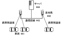
すなわち、第3実施形態は、第1及び第2実施形態で示したような道路情報処理装置を搭載した少なくとも1つの車両441と、各車両における道路情報処理装置の無線通信部141との無線通信を行う少なくとも1つの基地局442と、基地局442及びサーバ444を接続する通信回線443と、道路情報を管理するサーバ444とで構成される複合システムである。
【0108】
〔3−2.第3実施形態の作用〕
上記のように構成された第3実施形態では、側方距離情報を含む前記道路情報が路車間の無線通信によって交換され、各車両では、交換した道路情報に基づいて目的地への経路案内が行われる。
【0109】
具体的には、各車両441の道路情報処理装置は、すでに説明したような道路情報検出を行い、道路の形状を含む静的な道路情報と、渋滞情報や駐車施設情報を含む動的な道路情報を道路情報記録部103に記録する。そして、各車両441の無線通信部141は、最寄りの基地局442、通信回線443を介して、サーバ444に接続し、道路情報記録部103が持つ道路情報をサーバ444へ送信する。
【0110】
また、サーバ444は、各車両から道路情報を収集し、道路情報のデータベースの管理を行うとともに、各車両441に必要な道路情報を送信する。すると、道路情報を受信した車両441の道路情報処理部140は、受信した道路情報に基づいて道路情報記録部103の道路情報を更新し、その道路情報を用いてナビゲーション部104によるナビゲーションを行う。
【0111】
〔3−3.第3実施形態の効果〕
以上のような第3実施形態によれば、遠方を含む多くの車両が検出した道路情報をナビゲーションに利用することができる。また、サーバがナビゲーションシステム全体の道路情報を管理することにより、効率的な処理を行うことができる。
すなわち、第3実施形態では、通信ネットワークやサーバとの路車間通信により、多数の車両間で広範囲に多量の道路情報を集積し利用することが可能となるので、より合理的なナビゲーションが可能となる。
【0112】
〔4.他の実施形態〕
なお、本発明は上記各実施形態に限定されるものではなく、次に例示するような他の実施形態も包含するものである。例えば、上記各実施形態では本発明の典型的用途として、ナビゲーションシステムへの応用例を示したが、ナビゲーションシステムは必須ではなく、道路情報検出装置や道路情報処理装置などの単機能品も本発明の範囲内である。
【0113】
【発明の効果】
以上のように、この発明によれば、具体的道路状況に関する高精度な情報を広範囲にわたりリアルタイムに低コストで取得する情報処理技術、すなわち道路情報処理装置、方法及び道路情報処理用ソフトウェア、ナビゲーションシステム及び方法、並びに道路情報データベースの作成方法を提供することができる。
【図面の簡単な説明】
【図1】本発明の第1実施形態の構成を示す機能ブロック図。
【図2】本発明の第1実施形態において、側方距離検出の例を説明するための概念的平面図。
【図3】本発明の第1実施形態において、道路情報検出の例を説明するための概念的平面図。
【図4】本発明の第1実施形態における処理手順を示すフローチャート。
【図5】本発明の第1実施形態において、車両認識の例を説明するための概念的平面図。
【図6】本発明の第2実施形態の構成を示す機能ブロック図。
【図7】本発明の第2実施形態における道路情報の生成と通信の処理手順を示すフローチャート。
【図8】本発明の第2実施形態における道路情報交換の例を説明するための概念的平面図。
【図9】本発明の第2実施形態におけるすれ違い認識の例を説明するための概念的平面図。
【図10】本発明の第2実施形態における経路認識の例を説明するための概念的平面図。
【図11】本発明の第2実施形態における駐車施設認識の例を説明するための概念的平面図。
【図12】本発明の第3実施形態を示す構成図。
【符号の説明】
31,41…道路情報生成部
32,42…更新部
43…送受信制御部
44…すれ違い判断部
45…追従処理部
46…駐車施設判断部
101…側方距離検出部
102…車両位置検出部
103…道路情報記録部
104…ナビゲーション部
111,112…距離センサ
121…GPS受信機
122…ジャイロ
123…車速センサ
130…道路情報処理部
200…自車両
201,202…障害物
300…自車両
311…走行経路
312…道路
313…他車両
314…距離測定
321…検出経路
322…検出経路形状
323…検出物体形状
500…自車両
510…道路
511,512,513,514…他車両
520…検出経路形状
521,522,523,524…検出物体形状
140…道路情報処理部
141…無線通信部、
400…自車両
401…自車両経路
410…第1他車両
411…第1他車両経路
420…第2他車両
421…第2他車両経路
420…第3他車両
421…第3他車両経路
440…道路
450…自車両
451…他車両
461,462…障害物
600…自車両
601…道路
604,605,606…渋滞車両
607…幅員減少区間
610…第1候補経路
611…第1他車両
612…第1検出経路
613…第1検出経路形状
614,615,616…検出物体形状
620…第2候補経路
621…第2他車両
622…第2検出経路
623…第2検出経路形状
700…自車両
710…道路
711,712,713…駐車スペース
721,722,723…駐車スペース形状
730…他車両
731…検出経路
732…検出経路形状
441…車両
442…基地局
443…通信回線
444…サーバ[0001]
BACKGROUND OF THE INVENTION
The present invention relates to an improvement in technology relating to navigation, and in particular, obtains highly accurate information regarding a specific road condition over a wide range at a low cost in real time.
[0002]
[Prior art]
In recent years, with the spread of automobiles and the development of computer technology, navigation systems that are installed in vehicles such as automobiles and guide the optimal route to a destination are rapidly spreading. The navigation system sets the optimal route to the specified destination from road information recorded on a CD-ROM, etc., and determines the position of the vehicle in real time using GPS (Global Positioning System) or gyro, It is a guide to turn left and right turning points with map display and voice.
[0003]
Recently, in order to provide more detailed guidance, there are also examples in which specific road conditions such as road width are used for each place. For example, in Japanese Patent Laid-Open No. 10-86761 (vehicle information providing apparatus), a DGPS (Differential Global Positioning System) apparatus and a map database are connected to a navigation ECU (Electric Control Unit).
[0004]
This map database stores map information including road information of the whole country, and in particular, information on the width of the road, that is, data on the road configuration such as the width of the road and the width of the number of lanes. Has been. According to such a configuration, the width of the road and the width of several shoulders in the lane can be used in navigation.
[0005]
Also, for example, in Japanese Patent Laid-Open No. 11-144185 (automated driving control guidance system), a laser radar that detects the presence of an obstacle located in front of the vehicle, the shape of the road surface on the front road, and the positional relationship between the host vehicle and the lane are recognized. A CCD (Charge Coupled Device) camera, which is a photographing means, is provided at the front of the vehicle.
[0006]
In this conventional example, the image processing ECU outputs road surface data and own vehicle position data on the lane based on a video signal obtained from the CCD camera. Also, the overall plan ECU is based on information on obstacles ahead of the vehicle by laser radar, and traffic information such as road information or traffic jam information such as road surface conditions within a predetermined distance in front of the vehicle from the road-to-vehicle communication device. Driving instructions such as maintenance and lane change can be determined by the driving instruction process. According to such a configuration, the presence of obstacles ahead of the vehicle, the shape of the road surface on the front road, and the positional relationship between the host vehicle and the lane can be used in navigation.
[0007]
[Problems to be solved by the invention]
However, the conventional technology as described above has a problem in that it is impossible to collect highly accurate information regarding a specific road condition such as a parked vehicle over a wide range at a low cost.
[0008]
For example, when the width of all roads to be used is recorded in advance in a map database in order to perform navigation using the road width, such a detailed map database survey and creation requires enormous time and cost. Therefore, it is practically difficult to always use the latest information for navigation. In this case, since the road width information is fixed in advance, it is impossible to perform navigation corresponding to information on obstacles such as a congested train or a parked vehicle.
[0009]
On the other hand, in the conventional technique using a CCD camera or a laser radar, the road width in the front is calculated based on the detected obstacle data and image in the front, but in such a method, the accuracy in the road width direction is low, and the altitude There is a problem that the cost is increased due to the need for proper signal processing.
[0010]
The present invention has been proposed in order to solve the above-described problems of the prior art, and an object of the present invention is to obtain information processing technology for acquiring high-precision information regarding specific road conditions over a wide range at a low cost in real time. That is, to provide a road information processing apparatus, method, road information processing software, navigation system and method, and a road information database creation method.
[0011]
Another object of the present invention is to provide an information processing technique that realizes effective navigation such as avoiding a traffic jam section, and the specific objects correspond to the following configurations, operations, and effects, respectively.
[0012]
[Means for Solving the Problems]
In order to achieve the above object, the road information processing apparatus according to
[0013]
The invention of claim 7 captures the invention of
[0014]
The road information processing software according to claim 17 captures the inventions according to
[0015]
In these aspects, the lateral distance to the object is measured on the left and right sides of the own vehicle, and the position of the own vehicle in the road width direction, a congested vehicle, a parked vehicle, etc. New road information including the shape of the environment such as the arrangement of obstacles and the actual road shape can be calculated, and the road information can be updated. As a result, it is possible to acquire high-precision information regarding specific road conditions over a wide range in real time at low cost, and it can also be used for effective navigation.
[0016]
According to a second aspect of the present invention, in the road information processing apparatus according to the first aspect, the shape of the environment is discriminated and recorded on the basis of a change and size before and after the shape of the environment. Features.
[0017]
The invention according to claim 8 captures the invention according to
[0018]
The invention of claim 18 captures the inventions of
[0019]
In these aspects, the road and other vehicles, vending machines, etc. are discriminated based on whether the change in the width of the environment shape is gentle or sudden and whether it is within the size range of the vehicle. Thus, it becomes easy to use the obtained road information according to different purposes such as avoiding a traffic jam section or selecting a wide road.
[0020]
According to a third aspect of the present invention, in the road information processing apparatus according to the second aspect of the present invention, based on whether the shape other than the determined road is within a predetermined size range determined in advance for the vehicle, The shape and shape other than the vehicle are discriminated and recorded, and the discriminated arrangement of the vehicle is recorded as traffic jam information.
[0021]
The invention of claim 9 captures the invention of
[0022]
In these aspects, the shape of the vehicle other than the road is determined based on whether or not the vehicle is within a predetermined size range such as the length and aspect ratio, and the vehicle arrangement is recorded as traffic jam information. This makes it easy to distinguish road sections that tend to have a lot of vending machines, signboards, passers-by, etc., and more effective navigation becomes easier.
[0023]
According to a fourth aspect of the present invention, in the road information processing apparatus according to any one of the first to third aspects, the wireless communication means for transmitting / receiving the road information to / from the outside, and the road information received from the outside. And a means for updating the road information of the own vehicle.
[0024]
The invention of claim 10 captures the invention of
[0025]
In these aspects, road information can be more effectively used in each vehicle by transmitting and receiving road information through wireless communication with the outside such as between vehicles, between roads and vehicles, radio waves, and infrared rays.
[0026]
A navigation system according to claim 5 includes the road information processing apparatus according to any one of
[0027]
The navigation method of claim 11 is the method of grasping the invention of claim 5 from the viewpoint of a method, and includes the road information processing method according to any one of claims 7 to 10 and information on the lateral distance. And a process of exchanging the road information by wireless communication between vehicles and a process of performing route guidance to a destination based on the exchanged road information.
[0028]
In these aspects, road information can be exchanged and used between a plurality of vehicles, so that more rational navigation is possible, such as obtaining information on the area to go from oncoming vehicles.
[0029]
A navigation system according to a sixth aspect includes the road information processing apparatus according to any one of the first to fourth aspects, and means for exchanging the road information including the lateral distance information by radio communication between road vehicles. And means for performing route guidance to the destination based on the exchanged road information.
[0030]
A navigation method according to claim 12 is obtained by grasping the invention according to claim 6 from the viewpoint of a method, and includes the road information processing method according to any one of claims 7 to 10, wherein the information on the lateral distance is obtained. Including the process of exchanging the road information including road and vehicle wireless communication and the process of performing route guidance to the destination based on the exchanged road information.
[0031]
In these aspects, a large amount of road information can be accumulated and used in a wide range between a large number of vehicles by road-to-vehicle communication with a communication network or a server, so that more rational navigation is possible.
[0032]
A thirteenth aspect of the present invention is the road information processing method according to any one of the seventh to tenth aspects, wherein the vehicle width of each vehicle recorded in advance and the lateral distance measured by each vehicle are determined between the vehicles. It is characterized by predicting the margin in the passing of the vehicle by exchanging with.
[0033]
In this mode, between each vehicle trying to pass each other, the vehicle width of the vehicle and the measured lateral distance are exchanged with each other, and a margin in the passing is predicted, so that a passing or accident in a place with a lot of room is possible. Smooth operation of each vehicle becomes easy.
[0034]
A fourteenth aspect of the present invention is the road information processing method according to the ninth, tenth, or thirteenth aspect, wherein the vehicles are provided from a plurality of other vehicles by exchanging the arrangement of the vehicles determined between the vehicles. It is characterized by detecting the arrangement of a common vehicle and comparing the movement by comparing each of the arrangements.
[0035]
In this aspect, by comparing the vehicle length sequences detected by a plurality of other vehicles to detect the common part and following or tracking the movement, it is possible to know the average speed and traffic jam situation in other road sections This enables effective navigation such as accurate prediction of arrival times and avoidance of traffic jam sections.
[0036]
The invention of claim 15 is the road information processing method according to any one of claims 9, 10, 13 or 14, wherein information on where and what parking facilities are prepared in advance in each vehicle, The arrangement of the vehicles discriminated between the vehicles is exchanged, and the availability of the parking facility is judged from the arrangement of the vehicles discriminated by another vehicle for the place corresponding to the parking facility.
[0037]
In this mode, parking facilities such as parking meters can be pre-determined based on road information obtained from other vehicles that have passed through the location, so the number of empty spaces can be determined in advance. Effective navigation such as guiding other parking facilities becomes possible.
[0038]
The road information database creation method according to claim 16 measures a lateral distance to an object on the side of the host vehicle traveling on the road, detects a current position of the host vehicle, Pre-stored road information including at least the road width for each location with respect to the road; Based on the width of the host vehicle, the measured lateral distance, and the detected current position, create new road information including the shape of the environment for each location of the road, The road information stored in advance was created Update based on new road information, This updated New road information is recorded on the removable media, the removable media is collected from the vehicles, the recorded road information is read from the removable media and collected, and road information is based on the collected road information. It is characterized by creating a database.
[0039]
In this aspect, road information detected by each vehicle is recorded and collected on a portable information recording medium such as a memory card, that is, a removable medium, and a detailed road information database is created at low cost from the collected road information. Effective navigation according to the actual situation of each road section can be performed.
[0040]
DETAILED DESCRIPTION OF THE INVENTION
Next, a plurality of embodiments (hereinafter referred to as “embodiments”) of the present invention will be specifically described with reference to the accompanying drawings. Each embodiment relates to a navigation system including the road information processing apparatus of the present invention (hereinafter referred to as “the present system”), and a road information processing method and a navigation method executed on the system. Is realized by controlling the CPU and peripheral devices of the computer with software.
[0041]
Note that the hardware and software implementation modes in this case can be variously changed. For example, the above-described software or a machine-readable recording medium recording such software, such as a CD-ROM, a flash memory, or a ROM chip. A package or the like is also one embodiment of the present invention. For this reason, in the following description, a virtual circuit block corresponding to each function of the present invention and each embodiment is used.
[0042]
[1. First Embodiment]
[1-1. Configuration of First Embodiment]
1st Embodiment is an example which updates road information based on the detection of a side distance, and is provided with the following component shown in the functional block diagram of FIG. That is, the side distance detecting unit 101 is a means for measuring, that is, detecting a side distance to an object on the side of the host vehicle traveling on the road, and includes a plurality of
[0043]
The vehicle position detection unit 102 is a means for detecting the current position of the host vehicle, and includes a
[0044]
Further, the road
[0045]
Here, the road information is information indicating where and what roads exist. For example, nodes such as intersections and curve points are connected by links indicating distances, and convenience stores, if necessary, Accompanying information indicating landmarks such as gas stations and detailed road information for display. Further, the road information in the present embodiment includes dynamic information such as road congestion, parking facility congestion, and obstacles in addition to static information such as map information including the road width. Further, the road
[0046]
In addition, the
[0047]
In particular, the road
[0048]
Further, the road
[0049]
[1-2. Operation of First Embodiment]
The first embodiment configured as described above operates as follows.
[1-2-1. (Side distance detection)
First, the side distance detection operation will be described in detail. Here, FIG. 2 shows a conceptual plan view for illustrating an example of the operation of the lateral distance detection in the first embodiment. In this example, the distance sensor 111 is directed to the left side of the host vehicle 200, and the
[0050]
In this example, the side distance detection unit 101 shown in FIG. 1 has a distance l (lowercase L) from the left end of the host vehicle to the
[0051]
[1-2-2. (Generation and update of road information)
Next, generation and update of road information will be described in detail. That is, the road information generation unit 31 includes a new shape including the shape of the environment for each place of the road based on the width of the host vehicle stored in advance, the measured lateral distance, and the detected current position. Road information is generated. And the
[0052]
Here, FIG. 3 shows a conceptual plan view for illustrating an example of generation and update of road information in the first embodiment. 3A is a conceptual plan view showing the environment near the host vehicle, and FIG. 3B is a conceptual plan view showing road information detected by the host vehicle. FIG. 4 is a flowchart showing a processing procedure in generating and updating road information.
[0053]
Here, consider a case where the
[0054]
Further, the road
[0055]
When the static road information and the dynamic road information obtained in this way do not exist in the road
[1-2-3. (Specific operation of vehicle recognition)
[0056]
The operation of vehicle recognition in the first embodiment will be described in detail. That is, the road information generation unit 31 determines the shape of the vehicle and the shape other than the vehicle based on whether or not the determined shape other than the road is within a predetermined size range determined in advance for the vehicle. And the determined vehicle arrangement is recorded as traffic jam information.
[0057]
First, FIG. 5 shows a conceptual plan view for illustrating an example of the operation of vehicle recognition. Among these, Fig.5 (a) shows the environment of the own vehicle vicinity. Here, a case is considered where
[0058]
As a reference for vehicle recognition, for example, it is conceivable to recognize a vehicle when the aspect ratio of the detected object is within a predetermined range of about 1.2: 1 to 3: 1. In other words, the detected object shapes 521, 522, 523, and 524 are recognized based on such a standard, and if there is a possibility of the vehicle from the size, the detected object lengths d1, d2, d3, and d4 are recognized as the vehicle length. , The array is the array. This vehicle length array can be recorded in the road
[0059]
In addition, when the road
[0060]
That is, each vehicle is provided with a removable media read / write means, and in each vehicle, the lateral distance to an object on the side of the vehicle traveling on the road is measured, and the current position of the vehicle is detected and stored in advance. Based on the width of the own vehicle, the measured lateral distance, and the detected current position, new road information including the shape of the environment for each place of the road is created, and the new road information is Record each on removable media. Then, the producer collects removable media from each vehicle, reads and collects the recorded road information from each removable media, and creates a road information database based on the collected road information.
[0061]
[1-3. Effects of the first embodiment]
As described above, according to the first embodiment, the latest shape of the road environment can be detected and used for navigation. In particular, the first embodiment can be configured at low cost by using a distance sensor.
[0062]
That is, in the first embodiment, in each vehicle, the lateral distance to the object is measured on the left and right sides of the own vehicle, and the vehicle's position information in the road width direction is calculated by calculating the position information of the own vehicle and the own vehicle width. The road information can be updated by calculating new road information including the position, the arrangement of obstacles such as a congested vehicle and a parked vehicle, and the shape of the environment such as the actual road shape. As a result, it is possible to acquire high-precision information regarding specific road conditions over a wide range in real time at low cost, and it can also be used for effective navigation.
[0063]
In the first embodiment, the road and other vehicles and vending machines are changed based on whether the change in the width of the environment is gentle or sudden and whether the vehicle is within the size range of the vehicle. Etc., it becomes easy to use the obtained road information according to different purposes such as avoiding a traffic jam section or selecting a wide road.
[0064]
In the first embodiment, the shape other than the road is determined based on whether or not the vehicle is within a predetermined size range such as length and aspect ratio, and the vehicle arrangement is recorded as traffic jam information. In addition, it becomes easy to distinguish road sections that tend to be congested and road sections that have many vending machines, signboards, and passers-by, and more effective navigation becomes easier.
[0065]
In the first embodiment, the road information database manager collects and manages the road information detected by each vehicle, thereby creating and providing a road information database including the latest road shape and traffic jam information at low cost. can do.
[0066]
That is, in the first embodiment, road information detected by each vehicle is recorded and collected on a portable information recording medium such as a memory card, that is, a removable medium, and a detailed road information database is collected at low cost from the collected road information. It is possible to perform effective navigation in accordance with the actual situation of each road section.
[0067]
[2. Second Embodiment]
The second embodiment is an example in which inter-vehicle communication is performed using a communication function.
[2-1. Configuration of Second Embodiment]
That is, the second embodiment includes a
[0068]
That is, the
[0069]
The updating
[0070]
The road
[0071]
In addition, the road
[0072]
[2-2. Operation of Second Embodiment]
In the second embodiment configured as described above, a process of transmitting / receiving road information to / from the outside by wireless communication and a process of updating the road information of the host vehicle based on the road information received from the outside are performed. Here, the processing procedure in the second embodiment is shown in the flowchart of FIG. In FIG. 7, the processes from step S101 to S123 are the same as the processes indicated by the same reference numerals in FIG.
[0073]
That is, in the second embodiment, when the road information detection operation up to step S122 or S123 is completed, the
[0074]
Further, the road
[0075]
For example, if the passing determination unit 44 of the road
[0076]
Then, the updating
[0077]
[2-2-1. Example of navigation using inter-vehicle communication)
Next, an outline of navigation using inter-vehicle communication in the second embodiment as described above will be described. In this example, the transmission / reception control unit 43 and the
[0078]
First, FIG. 8 shows a conceptual plan view for explaining navigation using inter-vehicle communication. In this case, the navigation system can be grasped as a complex system including a road information processing apparatus and a navigation system mounted on a plurality of
[0079]
[2-2-2. Acquisition and exchange of road information)
Here, a case where the
[0080]
That is, the first
[0081]
Therefore, the
[0082]
[2-2-3. (Passing recognition behavior)
Next, the operation of passing recognition in the navigation system using inter-vehicle communication will be described in detail. In this process, the vehicle width of each vehicle recorded in advance and the lateral distance measured by each vehicle are exchanged between the vehicles, so that a margin in passing of the vehicles is predicted. Here, FIG. 9 is a conceptual plan view for explaining an example of the operation of passing recognition. In the road where the
[0083]
In this case, the
[0084]
[2-2-4. Vehicle following operation)
Next, the vehicle following operation in the navigation system using inter-vehicle communication will be described in detail. In this process, the arrangement of the vehicles determined between the vehicles is exchanged, and the arrangement of the vehicles provided from a plurality of other vehicles in each vehicle is collated to detect the arrangement of the common vehicles and move the vehicle. Follow. That is, as illustrated in FIG. 5, the vehicle that has recognized the vehicle transmits the vehicle length array to other nearby vehicles. Then, the road
[0085]
As a result of such comparison, if the elements match between a plurality of vehicle length arrays or a certain proportion of elements match, it is determined that the plurality of vehicle length arrays include the same vehicle. Then, vehicle tracking is performed by associating a plurality of received information positions and times. That is, the travel distance and travel time of the vehicle can be obtained from the position and time at which the same vehicle is detected, and can be used to determine traffic jam information such as the degree and length of the traffic jam and the estimated transit time. As described above, the travel distance and the travel time can be obtained also for the information of the vehicle not equipped with the navigation system in the present embodiment.
[0086]
[2-2-5. (Route recognition)
Next, the route recognition operation in the navigation system using inter-vehicle communication will be described. In this process, when there are a plurality of routes that can be selected by the own vehicle, the status of each route is determined (recognized) based on road information obtained from the other vehicle, and an appropriate route for the own vehicle is selected. First, FIG. 10 shows a conceptual plan view for explaining an example of a route recognition operation.
[0087]
Of these, FIG. 10A shows two candidate routes that the
[0088]
FIG. 10B shows road information detected by the first other vehicle 611 regarding the
[0089]
And when the
[0090]
FIG. 10C shows road information detected by the second other vehicle 621 regarding the
[0091]
When the
[0092]
Next, the road
[0093]
[2-2-6. (Parking facility recognition)
Next, an operation of recognizing a parking facility in a navigation system using inter-vehicle communication will be described. This corresponds to the information on the parking facility and the parking facility by preparing information on where and what parking facility is prepared in advance for each vehicle, exchanging the vehicle arrangement determined between the vehicles. The vacant condition of the parking facility is determined from the arrangement of the vehicles determined by other vehicles for the place.
[0094]
First, FIG. 11 shows a conceptual plan view for explaining an example of the operation of parking facility recognition. Here, consider a case where the
First, FIG. 11A shows an environment near a parking facility to which the
[0095]
FIG. 11B shows road information detected by the
[0096]
Then, the road
[0097]
When the
[0098]
Here, recognition of the empty space in the parking facility may not be performed by the detected
[0099]
[2-3. Effect of Second Embodiment]
As described above, according to the second embodiment, the latest road information including the surrounding road shape, traffic jam information, and parking facility information can be used for navigation. In addition, it is possible to configure a system that does not require infrastructure at low cost. Furthermore, since the vehicle equipped with the road information processing apparatus also detects nearby non-mounted vehicles, it is possible to obtain effective road information even in an environment where both mounted and non-mounted vehicles are present.
[0100]
That is, in the second embodiment, road information can be used more effectively in each vehicle by transmitting and receiving road information by wireless communication with outside such as between vehicles, between roads and vehicles, radio waves, and infrared rays.
[0101]
In particular, in the second embodiment, road information can be exchanged and used among a plurality of vehicles, so that more rational navigation is possible, such as obtaining information on the area to go from an oncoming vehicle.
[0102]
Also, in the second embodiment, between vehicles trying to pass each other, the vehicle width of the own vehicle and the measured side distance are exchanged with each other, and a margin in the passing is predicted, thereby passing each other in a place with a lot of room. Smooth operation of each vehicle becomes easy, such as preventing accidents.
[0103]
Further, in the second embodiment, by comparing the arrangements of the vehicle lengths detected in a plurality of other vehicles to detect a common portion and following the movement, the average speed and the traffic congestion situation in other road sections can be obtained. It is possible to know and effective navigation such as accurate prediction of arrival time and avoidance of traffic jam sections becomes possible.
[0104]
In the second embodiment, the parking facility such as a parking meter can be determined in advance based on road information obtained from other vehicles that have passed through the location, so that there is no space. In some cases, effective navigation is possible, such as guiding other nearby parking facilities.
[0105]
[3. Third Embodiment]
Next, 3rd Embodiment is related with the navigation system which exchanges the road information obtained as mentioned above by road-to-vehicle communication.
[0106]
[3-1. Configuration of Third Embodiment]
That is, in the third embodiment, road information including side distance information is exchanged by wireless communication between road vehicles, and route guidance to a destination is performed based on the exchanged road information. The configuration is shown in the functional block diagram of FIG.
[0107]
That is, in the third embodiment, wireless communication is performed between at least one vehicle 441 equipped with the road information processing apparatus as shown in the first and second embodiments and the
[0108]
[3-2. Operation of the third embodiment]
In the third embodiment configured as described above, the road information including side distance information is exchanged by wireless communication between road vehicles, and each vehicle provides route guidance to a destination based on the exchanged road information. Done.
[0109]
Specifically, the road information processing apparatus of each vehicle 441 performs road information detection as described above, and includes dynamic road information including static road information including the shape of the road, traffic jam information, and parking facility information. Information is recorded in the road
[0110]
The
[0111]
[3-3. Effects of the third embodiment]
According to the third embodiment as described above, road information detected by many vehicles including a distant place can be used for navigation. Moreover, efficient processing can be performed by the server managing the road information of the entire navigation system.
That is, in the third embodiment, road-to-vehicle communication with a communication network or server makes it possible to collect and use a large amount of road information over a wide range between a large number of vehicles, thereby enabling more rational navigation. Become.
[0112]
[4. Other embodiments]
In addition, this invention is not limited to said each embodiment, Other embodiments which are illustrated next are included. For example, in each of the above-described embodiments, the application example to the navigation system is shown as a typical application of the present invention. However, the navigation system is not essential, and single function products such as a road information detection device and a road information processing device are also included in the present invention. Is within the range.
[0113]
【The invention's effect】
As described above, according to the present invention, information processing technology for acquiring high-accuracy information regarding specific road conditions over a wide range at low cost in real time, that is, a road information processing apparatus, method, road information processing software, and navigation system And a method for creating a road information database can be provided.
[Brief description of the drawings]
FIG. 1 is a functional block diagram showing a configuration of a first embodiment of the present invention.
FIG. 2 is a conceptual plan view for explaining an example of side distance detection in the first embodiment of the present invention.
FIG. 3 is a conceptual plan view for explaining an example of road information detection in the first embodiment of the present invention.
FIG. 4 is a flowchart showing a processing procedure in the first embodiment of the present invention.
FIG. 5 is a conceptual plan view for explaining an example of vehicle recognition in the first embodiment of the present invention.
FIG. 6 is a functional block diagram showing a configuration of a second embodiment of the present invention.
FIG. 7 is a flowchart showing processing procedures for generating and communicating road information according to the second embodiment of the present invention.
FIG. 8 is a conceptual plan view for explaining an example of road information exchange in the second embodiment of the present invention.
FIG. 9 is a conceptual plan view for explaining an example of passing recognition in the second embodiment of the present invention.
FIG. 10 is a conceptual plan view for explaining an example of route recognition in the second embodiment of the present invention.
FIG. 11 is a conceptual plan view for explaining an example of parking facility recognition in the second embodiment of the present invention.
FIG. 12 is a configuration diagram showing a third embodiment of the present invention.
[Explanation of symbols]
31, 41 ... road information generation part
32, 42 ... Update unit
43. Transmission / reception control unit
44 ... Passing judgment part
45. Tracking processing unit
46 ... Parking Facility Judgment Department
101 ... Side distance detector
102: Vehicle position detection unit
103 ... road information recording part
104 ... navigation part
111, 112 ... distance sensor
121 ... GPS receiver
122 ... Gyro
123 ... Vehicle speed sensor
130 ... Road information processing department
200 ... Own vehicle
201, 202 ... Obstacles
300 ... Own vehicle
311 ... Traveling route
312 ... Road
313 ... Other vehicle
314 ... Distance measurement
321 ... Detection path
322 ... Detection path shape
323 ... Detected object shape
500 ... Own vehicle
510 ... Road
511, 512, 513, 514 ... Other vehicles
520 ... Detection path shape
521, 522, 523, 524 ... detected object shape
140 ... Road information processing department
141 ... wireless communication unit,
400 ... own vehicle
401 ... Own vehicle route
410 ... first other vehicle
411 ... First other vehicle route
420 ... Second other vehicle
421 ... Second other vehicle route
420 ... Third other vehicle
421 ... Third other vehicle route
440 ... Road
450 ... Own vehicle
451 ... Other vehicles
461, 462 ... Obstacles
600 ... Own vehicle
601 ... Road
604, 605, 606 ... Congested vehicles
607 ... Width reduction section
610: First candidate route
611 ... First other vehicle
612 ... First detection path
613 ... First detection path shape
614, 615, 616 ... detected object shape
620: Second candidate route
621 ... Second other vehicle
622 ... second detection path
623 ... second detection path shape
700 ... Own vehicle
710 ... Road
711, 712, 713 ... parking space
721, 722, 723 ... Parking space shape
730 ... Other vehicles
731 ... Detection path
732 ... Detection path shape
441 ... Vehicle
442 ... Base station
443 ... Communication line
444 ... Server
Claims (18)
道路を通行する自車両の側方の物体までの側方距離を計測する手段と、
自車両の現在位置を検出する手段と、
予め記憶された自車両の幅と、計測された前記側方距離と、検出された前記現在位置とに基づいて、道路の場所ごとの環境の形状を含む新たな道路情報を得る手段と、
前記道路情報を、前記新たな道路情報に基づいて更新する手段と、
前記側方距離の情報とその側方距離を検出した位置情報とを含む前記更新された道路情報を、車々間もしくは路車間の無線通信によって交換する手段と、
を備えたことを特徴とする道路情報処理装置。Means for storing road information including road width at least for each place regarding the road;
Means for measuring the lateral distance to the object on the side of the vehicle traveling on the road;
Means for detecting the current position of the host vehicle;
Means for obtaining new road information including the shape of the environment for each place of the road, based on the width of the host vehicle stored in advance, the measured lateral distance, and the detected current position;
Means for updating the road information based on the new road information;
Means for exchanging the updated road information including information on the side distance and position information on which the side distance is detected by wireless communication between vehicles or between road vehicles;
A road information processing apparatus comprising:
判別された前記車両の配列を渋滞情報として記録することを特徴とする請求項2記載の道路情報処理装置。Based on whether the determined shape other than the road is within a predetermined size range determined in advance for the vehicle, the shape of the vehicle and the shape other than the vehicle are determined and recorded,
The road information processing apparatus according to claim 2, wherein the determined arrangement of the vehicles is recorded as traffic jam information.
外部から受信した前記道路情報に基づいて自車両の道路情報を更新する手段と、
を備えたことを特徴とする請求項1から3のいずれか1つに記載の道路情報処理装置。Wireless communication means for transmitting and receiving the road information to and from the outside;
Means for updating the road information of the host vehicle based on the road information received from outside;
The road information processing apparatus according to any one of claims 1 to 3, further comprising:
前記側方距離の情報を含む前記道路情報を路車間の無線通信によって交換する手段と、
交換した道路情報に基づいて目的地への経路案内を行う手段と、
を備えたことを特徴とするナビゲーションシステム。Including the road information processing apparatus according to any one of claims 1 to 4,
Means for exchanging the road information including information on the side distance by radio communication between road vehicles;
Means for route guidance to the destination based on the exchanged road information,
A navigation system characterized by comprising:
道路を通行する自車両の側方の物体までの側方距離を計測する処理と、
自車両の現在位置を検出する処理と、
予め記憶された自車両の幅と、計測された前記側方距離と、検出された前記現在位置とに基づいて、道路の場所ごとの環境の形状を含む新たな道路情報を得る処理と、
前記道路情報を、前記新たな道路情報に基づいて更新する処理と、
前記側方距離の情報を含む前記道路情報を車々間もしくは路車間の無線通信によって交換する処理と、
を含むことを特徴とする道路情報処理方法。Prepare road information including road width at least for each place in advance,
Processing to measure the side distance to the object on the side of the vehicle traveling on the road,
A process for detecting the current position of the host vehicle;
A process of obtaining new road information including the shape of the environment for each road location based on the width of the host vehicle stored in advance, the measured lateral distance, and the detected current position;
Updating the road information based on the new road information;
Processing for exchanging the road information including information on the lateral distance between vehicles or between road vehicles; and
A road information processing method comprising:
判別された車両の配列を渋滞情報として記録することを特徴とする請求項8記載の道路情報処理方法。Based on whether the determined shape other than the road is within a predetermined size range determined in advance for the vehicle, the shape of the vehicle and the shape other than the vehicle are determined and recorded,
9. The road information processing method according to claim 8, wherein the determined arrangement of vehicles is recorded as traffic jam information.
を含むことを特徴とする請求項7から9のいずれか1つに記載の道路情報処理方法。A process of transmitting and receiving the road information to and from the outside by wireless communication; a process of updating the road information of the host vehicle based on the road information received from the outside;
The road information processing method according to claim 7, comprising:
前記側方距離の情報を含む前記道路情報を車々間の無線通信によって交換する処理と、
交換した道路情報に基づいて目的地への経路案内を行う処理と、を含むことを特徴とするナビゲーション方法。The road information processing method according to any one of claims 7 to 10,
A process of exchanging the road information including information on the lateral distance by wireless communication between vehicles;
And a process for performing route guidance to a destination based on the exchanged road information.
前記側方距離の情報を含む前記道路情報を路車間の無線通信によって交換する処理と、交換した道路情報に基づいて目的地への経路案内を行う処理と、を含むことを特徴とするナビゲーション方法。A road information processing method according to any one of claims 7 to 10,
A navigation method comprising: processing for exchanging the road information including the information on the lateral distance by radio communication between road vehicles; and processing for performing route guidance to a destination based on the exchanged road information. .
各車両間で判別された前記車両の配列を交換し、
前記駐車施設に該当する場所について他車両で判別された前記車両の配列とから、その駐車施設の空き状況を判断することを特徴とする請求項9,10,13又は14のいずれか1つに記載の道路情報処理方法。Information on where and what parking facilities are available in advance for each vehicle,
Exchange the vehicle arrangement determined between each vehicle,
The availability of the parking facility is determined from the arrangement of the vehicles determined by another vehicle for the location corresponding to the parking facility, according to any one of claims 9, 10, 13 or 14. The road information processing method described.
自車両の現在位置を検出し、
道路に関し少なくとも場所ごとの道路幅を含む予め記憶された道路情報と、自車両の幅と、計測された前記側方距離と、検出された前記現在位置とに基づいて、道路の場所ごとの環境の形状を含む新たな道路情報を作成し、
予め記憶された前記道路情報を、作成された新たな道路情報に基づいて更新し、
この更新した新たな道路情報をそれぞれ前記リムーバブルメディアに記録し、
前記各車両から前記リムーバブルメディアを収集し、
記録された道路情報を前記各リムーバブルメディアから読み出して収集し、
収集された道路情報に基づいて道路情報データベースを作成することを特徴とする道路情報データベースの作成方法。Measure the side distance to the object on the side of the vehicle traveling on the road,
Detect the current position of your vehicle,
Environment for each road location based on pre-stored road information including road width for each location, the width of the host vehicle, the measured lateral distance, and the detected current position with respect to the road Create new road information including the shape of
Updating the road information stored in advance based on the new road information created ,
Record this updated new road information on the removable media,
Collect the removable media from each vehicle,
Read and collect recorded road information from each removable media,
A road information database creation method comprising creating a road information database based on collected road information.
コンピュータを制御することにより、
道路を通行する自車両の側方の物体までの側方距離を計測させ、
自車両の現在位置を検出させ、道路に関し少なくとも場所ごとの道路幅を含む予め記憶された道路情報と、自車両の幅と、計測され車々間もしくは路車間の無線通信によって交換したものを含む前記側方距離と、検出された前記現在位置とに基づいて、道路の場所ごとの環境の形状を含む新たな道路情報を得させ、
予め記憶された前記道路情報を作成された前記新たな道路情報に基づいて更新させることを特徴とする道路情報処理用ソフトウェア。Prepare road information including road width at least for each place in advance,
By controlling the computer
Measure the side distance to the object on the side of the vehicle traveling on the road,
The above-mentioned side including the current position of the host vehicle , road information stored in advance including road width at least for each location regarding the road, the width of the host vehicle, and measured and exchanged between vehicles or between road vehicles Based on the distance and the detected current position, new road information including the shape of the environment for each road location is obtained,
Road information processing software , wherein the road information stored in advance is updated based on the created new road information.
Priority Applications (1)
| Application Number | Priority Date | Filing Date | Title |
|---|---|---|---|
| JP2001091297A JP4705259B2 (en) | 2001-03-27 | 2001-03-27 | Road information processing apparatus, method, road information processing software, navigation system and method, and road information database creation method |
Applications Claiming Priority (1)
| Application Number | Priority Date | Filing Date | Title |
|---|---|---|---|
| JP2001091297A JP4705259B2 (en) | 2001-03-27 | 2001-03-27 | Road information processing apparatus, method, road information processing software, navigation system and method, and road information database creation method |
Publications (2)
| Publication Number | Publication Date |
|---|---|
| JP2002288795A JP2002288795A (en) | 2002-10-04 |
| JP4705259B2 true JP4705259B2 (en) | 2011-06-22 |
Family
ID=18945940
Family Applications (1)
| Application Number | Title | Priority Date | Filing Date |
|---|---|---|---|
| JP2001091297A Expired - Fee Related JP4705259B2 (en) | 2001-03-27 | 2001-03-27 | Road information processing apparatus, method, road information processing software, navigation system and method, and road information database creation method |
Country Status (1)
| Country | Link |
|---|---|
| JP (1) | JP4705259B2 (en) |
Cited By (3)
| Publication number | Priority date | Publication date | Assignee | Title |
|---|---|---|---|---|
| WO2017041954A1 (en) * | 2015-09-11 | 2017-03-16 | Robert Bosch Gmbh | Method for detecting a parking area on a road section |
| US10288733B2 (en) | 2015-04-28 | 2019-05-14 | Robert Bosch Gmbh | Method for forecasting parking area availability of a street section |
| US10592756B2 (en) | 2015-09-11 | 2020-03-17 | Robert Bosch Gmbh | Method for detecting a parking area on a road section |
Families Citing this family (24)
| Publication number | Priority date | Publication date | Assignee | Title |
|---|---|---|---|---|
| JP3738762B2 (en) * | 2003-02-06 | 2006-01-25 | 日産自動車株式会社 | Vehicle travel control device |
| JP4114587B2 (en) * | 2003-09-29 | 2008-07-09 | 株式会社デンソー | Own vehicle travel position detection device and program |
| JP4715170B2 (en) * | 2003-11-21 | 2011-07-06 | 日産自動車株式会社 | Road information creation / distribution device, in-vehicle device, road information creation / distribution system |
| JP4339178B2 (en) * | 2004-05-12 | 2009-10-07 | アルパイン株式会社 | Parking space empty space guidance device and parking space empty space guidance method |
| JP4604683B2 (en) * | 2004-11-25 | 2011-01-05 | 日産自動車株式会社 | Hazardous situation warning device |
| JP4844098B2 (en) * | 2005-11-24 | 2011-12-21 | 株式会社ケンウッド | Navigation device, navigation method, navigation system, and traffic information guide program |
| JP4741394B2 (en) * | 2006-03-30 | 2011-08-03 | 株式会社トヨタマップマスター | Parking assistance system |
| JP2008174023A (en) * | 2007-01-16 | 2008-07-31 | Denso Corp | Passing automatic driving control device and driving support system |
| JP4715771B2 (en) * | 2007-02-28 | 2011-07-06 | 株式会社デンソー | Driving support system |
| JP4924292B2 (en) * | 2007-08-28 | 2012-04-25 | 株式会社デンソー | Information processing apparatus and program |
| JP4730378B2 (en) * | 2007-12-25 | 2011-07-20 | トヨタ自動車株式会社 | Course evaluation device and course evaluation method |
| JP4752836B2 (en) * | 2007-12-25 | 2011-08-17 | 日本電気株式会社 | Road environment information notification device and road environment information notification program |
| JP2009162569A (en) * | 2007-12-28 | 2009-07-23 | Aisin Aw Co Ltd | Navigation device and computer program |
| JP2009245339A (en) * | 2008-03-31 | 2009-10-22 | Aisin Aw Co Ltd | Apparatus, method and program for generating information |
| JP5012684B2 (en) * | 2008-06-20 | 2012-08-29 | トヨタ自動車株式会社 | Runway environment database generation system, moving body constituting the system, and runway environment database generation method |
| JP5299756B2 (en) * | 2008-09-24 | 2013-09-25 | 株式会社エクォス・リサーチ | vehicle |
| US20120277957A1 (en) * | 2010-04-15 | 2012-11-01 | Satoru Inoue | Driving assist device |
| JP6318999B2 (en) | 2014-09-04 | 2018-05-09 | 株式会社Soken | Parking space recognition device, parking space recognition system |
| JP6798779B2 (en) * | 2015-11-04 | 2020-12-09 | トヨタ自動車株式会社 | Map update judgment system |
| JP6789010B2 (en) * | 2016-06-29 | 2020-11-25 | 京セラ株式会社 | Driving support device, driving support method, imaging device, and vehicle |
| JP6824809B2 (en) * | 2017-04-26 | 2021-02-03 | 京セラ株式会社 | Driving support device, imaging system, vehicle, and driving support system |
| EP3480800A4 (en) * | 2016-06-29 | 2020-03-18 | KYOCERA Corporation | DRIVING ASSISTANCE DEVICE, IMAGING DEVICE, IMAGING SYSTEM, DRIVING ASSISTANCE SYSTEM, VEHICLE AND DRIVING ASSISTANCE METHOD |
| JP7204674B2 (en) * | 2017-12-28 | 2023-01-16 | 株式会社小糸製作所 | Vehicle lighting system, vehicle, vehicle-to-vehicle communication system and vehicle system |
| JP2022119106A (en) * | 2021-02-03 | 2022-08-16 | パナソニックIpマネジメント株式会社 | Vehicle and drive support device |
Family Cites Families (7)
| Publication number | Priority date | Publication date | Assignee | Title |
|---|---|---|---|---|
| JPS63237197A (en) * | 1987-03-25 | 1988-10-03 | 日本電気株式会社 | Transmission system of congestion information |
| JP3579121B2 (en) * | 1995-05-10 | 2004-10-20 | 富士通株式会社 | Route guidance system and map information utilization device |
| JPH09304083A (en) * | 1996-05-14 | 1997-11-28 | Toyota Motor Corp | Vehicle alarm system |
| JP2998694B2 (en) * | 1997-05-23 | 2000-01-11 | 日本電気株式会社 | Vehicle detection device |
| JP4200572B2 (en) * | 1999-01-18 | 2008-12-24 | 株式会社エクォス・リサーチ | Traffic jam detection device |
| JP4635280B2 (en) * | 1999-07-08 | 2011-02-23 | 株式会社Ihi | System and method for providing multimedia information to moving vehicles |
| JP3853542B2 (en) * | 1999-07-26 | 2006-12-06 | パイオニア株式会社 | Image processing apparatus, image processing method, and navigation apparatus |
-
2001
- 2001-03-27 JP JP2001091297A patent/JP4705259B2/en not_active Expired - Fee Related
Cited By (5)
| Publication number | Priority date | Publication date | Assignee | Title |
|---|---|---|---|---|
| US10288733B2 (en) | 2015-04-28 | 2019-05-14 | Robert Bosch Gmbh | Method for forecasting parking area availability of a street section |
| WO2017041954A1 (en) * | 2015-09-11 | 2017-03-16 | Robert Bosch Gmbh | Method for detecting a parking area on a road section |
| US10074277B2 (en) | 2015-09-11 | 2018-09-11 | Robert Bosch Gmbh | Method for ascertaining a parking area of a street section |
| US10592756B2 (en) | 2015-09-11 | 2020-03-17 | Robert Bosch Gmbh | Method for detecting a parking area on a road section |
| EP3347737B1 (en) * | 2015-09-11 | 2022-09-28 | Robert Bosch GmbH | Method for detecting a parking area on a road section |
Also Published As
| Publication number | Publication date |
|---|---|
| JP2002288795A (en) | 2002-10-04 |
Similar Documents
| Publication | Publication Date | Title |
|---|---|---|
| JP4705259B2 (en) | Road information processing apparatus, method, road information processing software, navigation system and method, and road information database creation method | |
| US11874119B2 (en) | Traffic boundary mapping | |
| JP7739515B2 (en) | System, computer program, and non-transitory computer-readable medium for navigating a vehicle | |
| US12344240B2 (en) | Systems and methods for selectively decelerating a vehicle | |
| RU2742213C1 (en) | Method to control information on lanes, method of traffic control and device for control of information on lanes | |
| CN110940347B (en) | A method and system for assisting vehicle navigation | |
| JP5126589B2 (en) | Parking assistance system | |
| US20180322777A1 (en) | Method and system for creating a lane-accurate occupancy grid map for lanes | |
| EP3550538B1 (en) | Information processing apparatus, information processing method, and program | |
| CN110546696A (en) | method for automatically generating and updating data sets for autonomous vehicles | |
| US20250095483A1 (en) | Systems and methods for generating source-agnostic trajectories | |
| CN113447035A (en) | Method, apparatus and computer program product for generating parking lot geometry | |
| JP3775394B2 (en) | Travel link determination system and link travel time measurement system | |
| JP6933069B2 (en) | Pathfinding device | |
| JP7447763B2 (en) | Mobile object detection device and control system | |
| US11680808B2 (en) | Map selection device, storage medium storing computer program for map selection and map selection method | |
| JP2001195693A (en) | Vehicle information transmitting device and traffic control system | |
| JP2002131067A (en) | Navigation device, base station device and road traffic information system using them | |
| US20250313233A1 (en) | Vehicle travel path determination | |
| CN117765754A (en) | An indoor parking induction method and system for autonomous driving | |
| JP7491023B2 (en) | Control equipment and control system | |
| KR20220135565A (en) | Indoor and outdoor continuous positioning switching device including domain and actor | |
| US12523492B2 (en) | Systems and methods for generating drop-off point maps | |
| JP2020204548A (en) | Current place acquiring system, and current place acquiring program | |
| JP2004251822A (en) | Navigation system |
Legal Events
| Date | Code | Title | Description |
|---|---|---|---|
| A621 | Written request for application examination |
Free format text: JAPANESE INTERMEDIATE CODE: A621 Effective date: 20080325 |
|
| A977 | Report on retrieval |
Free format text: JAPANESE INTERMEDIATE CODE: A971007 Effective date: 20100225 |
|
| A131 | Notification of reasons for refusal |
Free format text: JAPANESE INTERMEDIATE CODE: A131 Effective date: 20100302 |
|
| A521 | Request for written amendment filed |
Free format text: JAPANESE INTERMEDIATE CODE: A523 Effective date: 20100506 |
|
| A131 | Notification of reasons for refusal |
Free format text: JAPANESE INTERMEDIATE CODE: A131 Effective date: 20100907 |
|
| A521 | Request for written amendment filed |
Free format text: JAPANESE INTERMEDIATE CODE: A523 Effective date: 20101105 |
|
| A521 | Request for written amendment filed |
Free format text: JAPANESE INTERMEDIATE CODE: A523 Effective date: 20101105 |
|
| A01 | Written decision to grant a patent or to grant a registration (utility model) |
Free format text: JAPANESE INTERMEDIATE CODE: A01 Effective date: 20110222 |
|
| A61 | First payment of annual fees (during grant procedure) |
Free format text: JAPANESE INTERMEDIATE CODE: A61 Effective date: 20110311 |
|
| R250 | Receipt of annual fees |
Free format text: JAPANESE INTERMEDIATE CODE: R250 |
|
| R250 | Receipt of annual fees |
Free format text: JAPANESE INTERMEDIATE CODE: R250 |
|
| R250 | Receipt of annual fees |
Free format text: JAPANESE INTERMEDIATE CODE: R250 |
|
| LAPS | Cancellation because of no payment of annual fees |