JP4704569B2 - How to make a patterned concrete surface - Google Patents
How to make a patterned concrete surface Download PDFInfo
- Publication number
- JP4704569B2 JP4704569B2 JP2000599573A JP2000599573A JP4704569B2 JP 4704569 B2 JP4704569 B2 JP 4704569B2 JP 2000599573 A JP2000599573 A JP 2000599573A JP 2000599573 A JP2000599573 A JP 2000599573A JP 4704569 B2 JP4704569 B2 JP 4704569B2
- Authority
- JP
- Japan
- Prior art keywords
- concrete
- retarder
- printing
- formwork
- pattern
- Prior art date
- Legal status (The legal status is an assumption and is not a legal conclusion. Google has not performed a legal analysis and makes no representation as to the accuracy of the status listed.)
- Expired - Lifetime
Links
Images


Classifications
-
- B—PERFORMING OPERATIONS; TRANSPORTING
- B28—WORKING CEMENT, CLAY, OR STONE
- B28B—SHAPING CLAY OR OTHER CERAMIC COMPOSITIONS; SHAPING SLAG; SHAPING MIXTURES CONTAINING CEMENTITIOUS MATERIAL, e.g. PLASTER
- B28B7/00—Moulds; Cores; Mandrels
- B28B7/36—Linings or coatings, e.g. removable, absorbent linings, permanent anti-stick coatings; Linings becoming a non-permanent layer of the moulded article
-
- B—PERFORMING OPERATIONS; TRANSPORTING
- B28—WORKING CEMENT, CLAY, OR STONE
- B28B—SHAPING CLAY OR OTHER CERAMIC COMPOSITIONS; SHAPING SLAG; SHAPING MIXTURES CONTAINING CEMENTITIOUS MATERIAL, e.g. PLASTER
- B28B7/00—Moulds; Cores; Mandrels
- B28B7/38—Treating surfaces of moulds, cores, or mandrels to prevent sticking
-
- B—PERFORMING OPERATIONS; TRANSPORTING
- B28—WORKING CEMENT, CLAY, OR STONE
- B28B—SHAPING CLAY OR OTHER CERAMIC COMPOSITIONS; SHAPING SLAG; SHAPING MIXTURES CONTAINING CEMENTITIOUS MATERIAL, e.g. PLASTER
- B28B7/00—Moulds; Cores; Mandrels
- B28B7/36—Linings or coatings, e.g. removable, absorbent linings, permanent anti-stick coatings; Linings becoming a non-permanent layer of the moulded article
- B28B7/362—Linings or coatings, e.g. removable, absorbent linings, permanent anti-stick coatings; Linings becoming a non-permanent layer of the moulded article specially for making moulded articles from concrete with exposed aggregate
Landscapes
- Engineering & Computer Science (AREA)
- Manufacturing & Machinery (AREA)
- Chemical & Material Sciences (AREA)
- Ceramic Engineering (AREA)
- Mechanical Engineering (AREA)
- Moulds, Cores, Or Mandrels (AREA)
- Devices For Post-Treatments, Processing, Supply, Discharge, And Other Processes (AREA)
- Forms Removed On Construction Sites Or Auxiliary Members Thereof (AREA)
- Aftertreatments Of Artificial And Natural Stones (AREA)
- Application Of Or Painting With Fluid Materials (AREA)
- Glass Compositions (AREA)
- Producing Shaped Articles From Materials (AREA)
Abstract
Description
【0001】
【技術分野】
本発明はパターンドコンクリート(patterned concrete)表面を作る方法に関する。本方法は型枠及び打設技術(casting techniques)におけるコンクリートの表面構造を形作るための無数の可能性を提供する。本発明の方法は組立式ユニットの打設の場合も、現場での打ち込みの場合でも用いることができる。
【0002】
【従来技術】
従来は、コンクリート型枠及び打設技術を用いて、骨材露出コンクリート表面(exposed-aggregate concrete surface)を作るために、コンクリートの表面凝結を遅延させることが利用されていた。コンクリート表面凝結遅延剤(retarding agent)は現に存在する物質でコンクリートの硬化を遅延させる。コンクリート表面凝結遅延剤は骨材露出コンクリート表面を作るのに用いられる。
【0003】
他のものに囲まれた組立式のコンクリートユニットを打設するとき、表面凝結遅延剤を均一に塗布した紙を型枠の底に用いて、小型の骨材露出コンクリートユニットを作る。
【0004】
表面凝結遅延剤は、型枠の底に置いたある種のステンシルを通して、手で機械的に塗布して、ある個々のイメージを作るような方法である種の用途に明らかに用いられる。
【0005】
パターン化骨材露出コンクリートは予め決められた範囲で表面凝結遅延剤を用いて作ることができる方法もある。本発明と共通するものがある二つのそのような方法は、以下に詳細に説明する。しかしながら引用技術は明らかに本発明より技術的、及び経済的に劣るものである。
【0006】
一つの方法の着想が米国特許US−4055322に開示されている。この方法では、表面凝結遅延剤を透水性膜に塗布する。この膜は型枠内に置かれ、表面凝結遅延剤は型枠表面に直接接触し、コンクリートが膜上に打設される。表面凝結遅延剤が、機能を果たすためには、コンクリートから浸出する水のたすけによる拡散によって膜を通過してコンクリート表面に移動する必要がある。
【0007】
この方法の弱点は透水性が必要であり、表面凝結遅延剤が塗布される材料に、用いることができる材料が制限されることである。さらに、新しいコンクリートに要求されることは十分な水の浸出が含まれ、これはコントロールすることが困難である。このことは、特に現在のコンクリート技術では、長期間の耐久性を保証するコンクリートの品質は、正確には、浸出水が非常に微量であることを特徴としているという事情がある。透過膜もまた最終結果を弱めることになる。と云うのも、膜の中の凝結遅延剤が型枠の方向へ移動することについてこの特許の中では考慮されていないし、またおそらく防ぐことができないから。したがって、露出している表面と露出していない表面の間に明確な境界がない。全体的に見て、引用特許の方法による表面凝結遅延剤の挙動は今回出願した本特許の方法より決定的に劣るものである。
【0008】
実際に、米国特許US−4055322記載の方法で作られた、滑らかな打設コンクリートの表面の全てでコンクリートに直接接触している型枠材料は、上述のように透水膜であった。その膜は滑らかな打設表面の品質に好ましくない、少なくとも制御不能な影響を及ぼすものである。
【0009】
欧州特許EP−0052237に開示されている他の方法では、通常の表面凝結遅延剤膜が用いられ、骨材の露出した表面が望まれない部分の膜を被覆する表面処理がなされている。
この方法は、表面凝結遅延剤膜がパターン化されるべき全部の範囲に必要であって非経済的である。実際に、滑らかな打設表面には膜だけでなく、2層の化学薬品、即ち、表面凝結遅延剤とワニスがある。さらに、引用技術の方法は、一度に一つの表面凝結遅延剤のみを用いることができるということで本発明とは決定的に異なる。
【0010】
【発明の開示】
本発明は、表面凝結遅延剤を印刷技術か出力(output)技術のいずれかで応用するという新しい概念を作る試みに表面凝結遅延剤を用いる。
ここで開示する本方法では、引用方法とは異なり、作られる滑らかな打設表面の性質に影響を及ぼす機会を提供することで優れている。一般的に知られているように、型枠表面に塗布された剥離剤(release agent)はそれ自身が、作られる滑らかな打設表面の性質に影響する。数種の異なる剥離剤が種々の型枠材や種々のグレードのコンクリートに適するように開発された。剥離剤は例えば、大きく分けて以下のようなグループに分けることができる:
−純粋な鉱物油
−化学修飾植物油
−植物油と鉱物油の混合物
−乳化鉱物油
−乳化植物油
ここで開示された方法によると、適切な剥離剤を表面凝結遅延剤が塗布されていない部分の膜に塗布することができる。こうすることによって所望の品質の滑らかな打設表面を作ることができる。
【0011】
この実施態様の他の利点は、パターン化を全くしない組立式ユニットにおいて、滑らかな型枠の表面に膜に用いるのと同じ剥離剤を塗布することで足りることである。前述の引用方法にはこの利点を有していない。その代わりに、両方法ではもし全く滑らかな打設ユニットの表面が、部分的に骨材が露出したユニットの滑らかな打設表面と同じであることを望む場合には、膜をこれらのユニットに掛けなければならない。ここでもまたコンクリート製造業者は滑らかな打設表面の性質に影響を及ぼすことができない。
【0012】
本発明の方法は以下の性質を有する解決策を達成することを意図したものである:
1.本方法は、コンクリート打設技術において、各種のグラフィックレリーフ表
面とユニットの継ぎ目をデザインの一部として考えることができる新種のコン
クリートの表面処理を創造するのに用いることができる。
2.本方法はデザイナーが各種のグラフィックパターンを使ってコンクリート表
面の外見を形作るための無数の可能性を提供する。
3.本方法はできるだけ融通性があり、種々の種類のコンクリート打設に適用で
きる。
4.本方法の出発点は、できるだけ多くのデザイナーに役に立つ製品であること
。デザイナーはデーターネットワークを通してでき上がったデザインを、それ
を製造する工場に送ることもできる。
5.主な目的は、雨水の流水や都市の空気の汚染に関して、デザイン中から表面
の汚れを予測することができること。
6.従来のコンクリート表面と比較して、著しいコスト増加を避ける。
【0013】
本方法は、型枠技術や打設技術において、印刷技術や出力技術により、コンクリート表面凝結遅延剤、所望により剥離剤や他の所望する物質を用いることを基本とする。所望の表面パターンは、顔料としてコンクリート表面凝結遅延剤を用いる印刷技術や出力技術により型枠の打設表面に転写される。最近の印刷技術や出力技術によれば、所望により、同時、若しくは順次に、コンクリート表面に異なる効果を与える数種の異なる表面凝結遅延剤や他の物質を添加することができる。これは本発明の基本的な原則が特定のパターンの形成のみならず、表面凝結遅延剤が添加されず、結果として剥離剤や他の物質がコンクリート表面に影響を及ぼす領域の面仕上げ、及び形成されるコンクリート片の品質も含むためである。表面凝結遅延剤は深度が異なるところに作用するタイプが含まれる。
【0014】
型枠の打設表面は、膜様の材料、例えばコーテェッドペ−パーや何か他の材料が特に好ましく、それにパターンを、表面凝結遅延剤が印刷剤や出力剤として作用する印刷または出力技術で転写する。その技術はセリグラフィー、フレキソ印刷、デジタル出力技術、または他の印刷、出力技術であってもよい。一度、打ち込まれたコンクリートが硬化すると、型枠からはずされコンクリート片は洗浄され、型枠に表面凝結遅延剤があった骨材露出表面の部分にパターンが形成される。
【0015】
本方法はコンクリート表面をパターン化する既知の方法よりいくつかの利点がある。組立式コンクリートユニットでパターンを作る既知の方法は、型枠の底に取り付けた種々のプロフィール、型枠の底にステンシルによりブラシで塗布され凝結遅延した表面、コンクリートユニットの表面に砂を吹き付けたパターン、またはコンクリートユニットの機械的溝きりを含む。これらの既知の方法は多くが手作業工程であるため、時間がかかり、より制限されないパターンをコンクリート表面に作成するのには不都合である。上記の記載されている引用技術と比較して、本発明の方法は、より多様性があり経済的にも環境面からもより合理的である。
【0016】
本発明による新しい方法は、高度に自動化された生産と、パターンを変えることの無数の可能性とを可能にする。後で実施態様の図や実施例により説明するように、本発明は各種の深さに作用させるのが容易であるために製造されるコンクリート片の表面に立体感のある効果を創るのに使用することができる。
【0017】
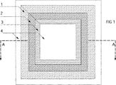
本発明を以下に添付図を引用することによってより詳細に説明する:図1,2及び3には層の実際の厚さを示すことを意図するものではなく、明確にするために層がかなりの厚さで描かれている。実際には、層は非常に薄い。最終的には中心になるコンクリート表面に露出する骨材粒子は図2には意図的に描かれていない。
図に示される実施例においては、異なる洗浄深度をもたらすように硬化を遅延する3種の凝結遅延剤が用いられており、これらは印刷技術や出力技術で表面に塗布される。参照番号1,2及び3はこれらの層を示す。番号1で示される凝結遅延剤は図2のプロフィールで示されるように最も深い深度に至るまでコンクリートの硬化を遅延する。番号2で示される薬剤は中間の効果で、番号3のものは最も遅延効果が小さいものである。
【0018】
図1に示されるように、表面凝結遅延剤よってできたパターンははっきりしており、外郭線は鮮明になっている。このように表面凝結遅延剤はまた直接鮮明に描かれたイメージを作る。図では、参照番号4は 剥離剤を示し、剥離剤は表面凝結遅延剤と同じような技術で表面に添加される。一般的に、各種の材料を添加するために同じ作業段階または順次の作業段階を利用することができる。同様に、異なる物質を塗布するとき、所望によっては、出力技術を一つの物質に、印刷技術を他の物質に用いることができる。例えば、ある物質はより容易に塗布できるある技術を、他の物質にはより容易に塗布できる他の技術を選択することができる。
物質1,2,3および4が印刷または出力技術で転写される本質的に水非透過膜は番号5で示される。番号6は型枠圧盤を示し、その上にパターン化表面凝結遅延剤膜が置かれる。図2では、参照番号7がコンクリートを示している。
以下に本方法について実施例を用いて説明する。
【0019】
【実施例1】
膜へのセリグラフィー
コンクリート表面凝結遅延剤を印刷インクとして用いるセリグラフィーを用いて所望の表面パターンを膜に転写する。これは、膜に所望のパターンを形成するコンクリート表面凝結遅延剤を使ってパターン化された表面凝結遅延剤膜を作る。セリグラフィーは現存する半自動化技術である。セリグラフィーでは所望の数の表面凝結遅延剤、剥離剤、または他の物質を印刷することができる。コンクリート工場ではパターン化された表面凝結遅延剤膜が型枠の底に広げられ、コンクリート材料が型枠に流される。一度コンクリートが硬化すると、コンクリートユニットが型枠からはずされ、その表面を洗浄する。膜に表面凝結遅延剤があったコンクリートの表面の部分にパターンが現れる。
【0020】
適切なタイプの膜を選択することによりその工程の間に、及び所望によりユニット打設型枠の底に孔をあけ、形成された孔を真空貯蔵器に繋ぐことにより、表面凝結遅延剤膜がくしゃくしゃになるのを防ぐ。真空にすることにより表面凝結遅延剤膜はしっかりと型枠の底に保持される。現場での打設では、パターン化された表面遅延材膜は、本発明に従って接着剤で型枠の打設表面に膜を固定するような方法で用いることができる。
【0021】
【実施例2】
膜へのフレキソ印刷
所望の表面パターンを印刷インクとしてコンクリート表面凝結遅延剤を用いて、フレキソ印刷機で膜に印刷する。フレキソ印刷機は、いわゆるローラー印刷機であり、印刷版がローラーの周りに付けられている。フレキソ印刷機は、機械によるが、3〜5メーターの模様や3メータ長の繰返しパターンを印刷することができる。フレキソ印刷機は一度に同じ作業工程で4色の印刷ができる。フレキソ技術は一般的に大規模な印刷操業にはセリグラフィーより経済的と考えられている。コンクリート打設において、この技術で印刷された表面凝結遅延剤膜が実施例1と同じような方法で用いられる。
【0022】
【実施例3】
デジタル出力技術
所望の表面パターンがデジタル印刷機にプログラムされ、当該デジタル印刷機は5メーター巾までの模様を印刷することができる。出力模様の長さは制限されないが、ファイルの長さの分だけの長さであり得、例えば、5キロメーター長の変化するパターンを出力することができる。そのようなデジタル出力印刷機は、印刷のノズルが印刷材料から十分に離れているために、どのような物質にも印刷することができる。そのような印刷機は少なくとも自動車産業において、個別の塗装が施された自動車に対する注文に応じるために用いられているのが見受けられる。
【0023】
コンクリート表面凝結遅延剤や剥離剤はデジタル印刷機でパターン化表面凝結遅延剤膜を製造するときに印刷インクとして用いられる。これらの物質はその機械で通常使われる顔料と同じ粘度に作られる。印刷される物質の層の厚さは制限がなくデジタルで調製することができる。そのようなデジタル印刷機は所望のパターンを所望の材料にデジタルに印刷することができる。印刷材料は、例えば、非透水性膜、型枠合板、若しくはコンクリートユニット型枠の底、一般的にはステンレス鋼であるが、等である。
【0024】
この技術による表面凝結遅延剤膜の生産物は、実施例1と同様に組み立て式コンクリートユニットを打設するのに使われる。この技術を用いてコンクリート表面凝結遅延剤パターンで印刷された型枠合板を現場での打設に用いることができる。この技術を用いてコンクリート表面凝結遅延剤パターンで印刷された型枠の底は組み立て式コンクリートユニット打設技術に用いられる。
【図面の簡単な説明】
【図1】上述のことから直接分かるように本発明により作られた1解決方法を示す;
【図2】本方法を利用することにより得られたコンクリート片の断面図を示す;
【図3】図1のA−A断面図を示す。
【符号の説明】
1、2,3:凝結遅延剤層
4:剥離剤
5:水非透過膜
6:型枠圧盤
7:コンクリート[0001]
【Technical field】
The present invention relates to a method of making a patterned concrete surface. This method offers a myriad of possibilities for shaping the surface structure of concrete in formwork and casting techniques. The method according to the invention can be used both for assembling assembling units and for field driving.
[0002]
[Prior art]
Traditionally, delaying the surface setting of concrete has been used to create an exposed-aggregate concrete surface using concrete formwork and casting techniques. A concrete surface retarding agent is a substance present to retard the hardening of concrete. Concrete surface setting retarders are used to make aggregate exposed concrete surfaces.
[0003]
When placing a prefabricated concrete unit surrounded by others, a small aggregate-exposed concrete unit is made using paper uniformly coated with a surface retarder on the bottom of the formwork.
[0004]
Surface retarders are clearly used in certain applications in such a way that they are mechanically applied by hand through certain stencils placed at the bottom of the mold to create certain individual images.
[0005]
There is also a method in which the patterned aggregate exposed concrete can be made using a surface setting retarder in a predetermined range. Two such methods in common with the present invention are described in detail below. However, the cited technique is clearly technically and economically inferior to the present invention.
[0006]
One method idea is disclosed in US Pat. No. 4,055,322. In this method, a surface setting retarder is applied to the water permeable membrane. This film is placed in the mold, the surface retarder is in direct contact with the mold surface, and concrete is cast on the film. In order for the surface setting retarder to perform its function, it must move through the membrane to the concrete surface by diffusion due to the water leaching from the concrete.
[0007]
The weakness of this method is that it requires water permeability and limits the materials that can be used for the material to which the surface retarder is applied. Furthermore, what is required of new concrete involves sufficient water leaching, which is difficult to control. This is particularly the case with current concrete technology, where the quality of concrete that guarantees long-term durability is precisely characterized by very small amounts of leachate. A permeable membrane will also weaken the final result. This is because the patent does not take into account and probably cannot prevent the setting retarder in the membrane from moving in the direction of the mold. Thus, there is no clear boundary between the exposed and unexposed surfaces. Overall, the behavior of the surface retarder according to the method of the cited patent is decisively inferior to that of the presently filed patent.
[0008]
In fact, the formwork material made by the method described in US Pat. No. 4,055,322 and in direct contact with the concrete on all smooth cast concrete surfaces was a water permeable membrane as described above. The film has an undesirable, at least uncontrollable effect on the quality of the smooth casting surface.
[0009]
In another method disclosed in European Patent EP-0052237, a normal surface setting retarder film is used, and a surface treatment is performed in which the exposed surface of the aggregate covers the film of an undesired portion.
This method is uneconomical, requiring a surface retarder film over the entire area to be patterned. In fact, the smooth casting surface has not only a film, but also two layers of chemicals: a surface retarder and a varnish. Furthermore, the cited technique method differs from the present invention in that only one surface set retarder can be used at a time.
[0010]
DISCLOSURE OF THE INVENTION
The present invention uses surface retarder in an attempt to create a new concept of applying surface retarder in either printing technology or output technology.
The presently disclosed method is superior to the cited method by providing an opportunity to affect the properties of the smooth casting surface that is created. As is generally known, the release agent applied to the mold surface itself affects the nature of the smooth casting surface that is created. Several different release agents have been developed to suit various formwork and various grades of concrete. For example, release agents can be broadly divided into the following groups:
-Pure mineral oil-Chemically modified vegetable oil-Mixture of vegetable oil and mineral oil-Emulsified mineral oil-Emulsified vegetable oil According to the method disclosed herein, a suitable stripping agent is applied to the part of the film where the surface retarder is not applied. Can be applied. By doing so, a smooth casting surface of the desired quality can be made.
[0011]
Another advantage of this embodiment is that it is sufficient to apply the same release agent as used for the film to the surface of the smooth formwork in the assembly unit without any patterning. The above cited method does not have this advantage. Instead, in both methods, if it is desired that the completely smooth casting unit surface be the same as the smooth casting surface of the partially exposed unit, the membrane is applied to these units. I have to hang it. Again, the concrete manufacturer cannot influence the properties of the smooth casting surface.
[0012]
The method of the present invention is intended to achieve a solution having the following properties:
1. The method can be used in concrete placement technology to create a new kind of concrete surface treatment that can be considered as part of the design of various graphic relief surfaces and unit seams.
2. This method offers a myriad of possibilities for designers to shape the appearance of concrete surfaces using a variety of graphic patterns.
3. This method is as flexible as possible and can be applied to various types of concrete placement.
4). The starting point for this method is a product that is useful to as many designers as possible. Designers can also send designs created through the data network to the factories that produce them.
5. The main objective is to be able to predict surface contamination from the design with regard to rainwater runoff and urban air pollution.
6). Avoid significant cost increases compared to conventional concrete surfaces.
[0013]
This method is based on the use of a concrete surface setting retarder, optionally a release agent and other desired substances in the formwork and placement techniques, by printing and output techniques. The desired surface pattern is transferred to the casting surface of the mold by a printing technique or output technique using a concrete surface setting retarder as a pigment. According to recent printing techniques and output techniques, several different surface setting retarders and other substances that have different effects on the concrete surface can be added simultaneously or sequentially as desired. This is because the basic principle of the present invention is not only the formation of a specific pattern, but also the surface finishing and formation of areas where surface retardants are not added, resulting in release agents and other substances affecting the concrete surface This is because the quality of the concrete pieces to be processed is included. Surface retarders include types that act at different depths.
[0014]
The casting surface of the mold is preferably a film-like material, such as coated paper or some other material, and the pattern is transferred to it by a printing or output technique in which the surface retarder acts as a printing or output agent. To do. The technology may be serigraphy, flexographic printing, digital output technology, or other printing, output technology. Once the poured concrete has hardened, it is removed from the formwork and the concrete pieces are washed, and a pattern is formed on the part of the aggregate exposed surface where the surface setting retarder was on the formwork.
[0015]
This method has several advantages over known methods of patterning concrete surfaces. Known methods for making patterns with prefabricated concrete units include various profiles attached to the bottom of the formwork, a surface that has been brushed with a stencil on the bottom of the formwork, and a pattern in which sand is sprayed onto the surface of the concrete unit. Or include mechanical grooving of concrete units. Since many of these known methods are manual processes, they are time consuming and inconvenient for creating less restrictive patterns on concrete surfaces. Compared to the cited technique described above, the method of the present invention is more versatile and more economical and economical.
[0016]
The new method according to the invention enables highly automated production and countless possibilities for changing patterns. The present invention is used to create a three-dimensional effect on the surface of a manufactured concrete piece because it can be easily applied to various depths, as will be described later with reference to the embodiments and examples. can do.
[0017]
The invention will now be described in more detail by reference to the accompanying drawings: FIGS. 1, 2 and 3 are not intended to show the actual thickness of the layers, but rather the layers are It is drawn with thickness. In practice, the layer is very thin. Aggregate particles that are ultimately exposed on the central concrete surface are not intentionally depicted in FIG.
In the embodiment shown in FIG, 3 kinds of setting retarder for delaying the curing to provide different cleaning depths have been used, which are applied to the surface by printing techniques or output techniques.
[0018]
As shown in FIG. 1, the pattern formed by the surface setting retarder is clear and the outline is sharp. Thus, the surface retarder also creates a directly drawn image. In the figure,
The essentially water-impermeable membrane to which the
Hereinafter, this method will be described with reference to examples.
[0019]
[Example 1]
Serigraphy to membrane The desired surface pattern is transferred to the membrane using serigraphy using a concrete surface set retarder as the printing ink. This creates a patterned surface retarder film using a concrete surface retarder that forms the desired pattern in the film. Serigraphy is an existing semi-automated technology. Serigraphy can print as many surface retarders, release agents, or other materials as desired. In a concrete factory, a patterned surface retarder film is spread on the bottom of the formwork and the concrete material is poured into the formwork. Once the concrete has hardened, the concrete unit is removed from the formwork and the surface is cleaned. A pattern appears on the surface of the concrete where the film has a surface retarder.
[0020]
During the process by selecting the appropriate type of membrane, and optionally drilling holes in the bottom of the unit casting form, and connecting the formed holes to a vacuum reservoir, the surface set retarder membrane is Prevent crumpled. By applying a vacuum, the surface retarder film is firmly held at the bottom of the mold. For on-site casting, the patterned surface retarder film can be used in a manner that secures the film to the casting surface of the mold with an adhesive in accordance with the present invention.
[0021]
[Example 2]
Flexographic printing on membranes A desired surface pattern is printed on a membrane with a flexographic press using a concrete surface set retarder as printing ink. The flexographic printing machine is a so-called roller printing machine, and a printing plate is attached around a roller. Depending on the machine, flexographic printing machines can print 3-5 meter patterns and 3 meter long repeat patterns. The flexo printing machine can print four colors at the same time. Flexo technology is generally considered more economical than serigraphy for large-scale printing operations. In concrete casting, a surface retarder film printed by this technique is used in the same manner as in Example 1.
[0022]
[Example 3]
Digital output technology The desired surface pattern is programmed into a digital printer, which can print patterns up to 5 meters wide. The length of the output pattern is not limited, but can be as long as the length of the file. For example, a changing pattern having a length of 5 kilometer can be output . Such digital output printers can print on any substance because the printing nozzles are sufficiently separated from the printing material . Such printing presses are found to be used at least in the automotive industry to fulfill orders for individually painted vehicles.
[0023]
Concrete surface set retarders and release agents are used as printing inks in the production of patterned surface set retarders films on digital printers. These materials are made to the same viscosity as the pigments normally used in the machine. The thickness of the printed material layer is not limited and can be prepared digitally. Such digital printers can digitally print a desired pattern on a desired material. The printing material is, for example, a water-impermeable membrane, a formwork plywood, or the bottom of a concrete unit formwork, typically stainless steel, etc.
[0024]
The product of the surface retarder film by this technique is used to cast a prefabricated concrete unit as in Example 1. Formwork plywood printed with a concrete surface setting retarder pattern using this technique can be used for on-site placement. The bottom of the formwork printed with the concrete surface setting retarder pattern using this technique is used in the assembly concrete unit placement technique.
[Brief description of the drawings]
1 shows one solution made according to the present invention as can be seen directly from the above;
FIG. 2 shows a cross-sectional view of a concrete piece obtained by using the method;
FIG. 3 is a cross-sectional view taken along the line AA of FIG.
[Explanation of symbols]
1, 2, 3: Setting retarder layer 4: Release agent 5: Water impermeable membrane 6: Form platen 7: Concrete
Claims (6)
Applications Claiming Priority (3)
| Application Number | Priority Date | Filing Date | Title |
|---|---|---|---|
| FI990326 | 1999-02-17 | ||
| FI990326A FI990326A0 (en) | 1999-02-17 | 1999-02-17 | Method for providing a textured concrete surface |
| PCT/FI2000/000122 WO2000048808A2 (en) | 1999-02-17 | 2000-02-17 | A method for creating a patterned concrete surface |
Publications (3)
| Publication Number | Publication Date |
|---|---|
| JP2002537141A JP2002537141A (en) | 2002-11-05 |
| JP2002537141A5 JP2002537141A5 (en) | 2010-09-24 |
| JP4704569B2 true JP4704569B2 (en) | 2011-06-15 |
Family
ID=8553807
Family Applications (1)
| Application Number | Title | Priority Date | Filing Date |
|---|---|---|---|
| JP2000599573A Expired - Lifetime JP4704569B2 (en) | 1999-02-17 | 2000-02-17 | How to make a patterned concrete surface |
Country Status (15)
| Country | Link |
|---|---|
| US (1) | US6803006B1 (en) |
| EP (1) | EP1177081B1 (en) |
| JP (1) | JP4704569B2 (en) |
| KR (1) | KR100660987B1 (en) |
| CN (1) | CN1142053C (en) |
| AT (1) | ATE294054T1 (en) |
| AU (1) | AU756993B2 (en) |
| BR (1) | BR0008309B1 (en) |
| CA (1) | CA2360881C (en) |
| DE (1) | DE60019742T2 (en) |
| DK (1) | DK1177081T3 (en) |
| ES (1) | ES2241577T3 (en) |
| FI (1) | FI990326A0 (en) |
| WO (1) | WO2000048808A2 (en) |
| ZA (1) | ZA200107541B (en) |
Cited By (1)
| Publication number | Priority date | Publication date | Assignee | Title |
|---|---|---|---|---|
| KR102019605B1 (en) * | 2018-06-26 | 2019-11-04 | 김성진 | Manufacturing method for design concrete panel and design concrete panel manufactured by this same |
Families Citing this family (23)
| Publication number | Priority date | Publication date | Assignee | Title |
|---|---|---|---|---|
| US7410351B2 (en) * | 2003-12-10 | 2008-08-12 | High Steven L | Chemical induced pre-stressed zones in concrete |
| US20070164484A1 (en) * | 2006-01-13 | 2007-07-19 | Francis Piccolo | Method of manufacturing molded products having surface designs |
| DE102010052250A1 (en) * | 2010-11-23 | 2012-05-24 | Hebau Gmbh | Liquid preparation used for manufacturing concrete surfaces, comprises washing-exposed aggregate concrete contact retarder and film-forming agent |
| JP5865122B2 (en) * | 2012-02-29 | 2016-02-17 | 日本興業株式会社 | Concrete products |
| FR2992961B1 (en) * | 2012-07-04 | 2014-08-29 | Chryso | METHOD OF CREATING PATTERNS ON A CONCRETE SURFACE |
| EP2789439A1 (en) | 2013-04-09 | 2014-10-15 | Niels Pieter Gerard Nieuweboer | Method for manufacturing a variety of esthetic concrete surfaces using metal molds and a magnetic substrate |
| CN106116690A (en) * | 2015-06-23 | 2016-11-16 | 德国莱利化工科技有限公司 | Erosion slow setting facing art transfer film washed by concrete |
| FR3039541B1 (en) * | 2015-07-31 | 2017-09-08 | Chryso | METHOD OF CREATING PATTERNS ON THE SURFACE OF A HYDRAULIC BINDER BASED COMPOSITION BY PRINTING |
| DE102015115748A1 (en) * | 2015-09-17 | 2017-03-23 | Kennwert RD GmbH | Process for the production of integrated circuits on or in concrete |
| CN105332497A (en) * | 2015-10-27 | 2016-02-17 | 大连山泰新实业有限公司 | Construction method of using color concrete to cover embossed surface |
| CN106393395A (en) * | 2016-09-22 | 2017-02-15 | 黄贺明 | Manufacturing method for concrete decorative hanging plate |
| JP6880688B2 (en) * | 2016-12-07 | 2021-06-02 | 凸版印刷株式会社 | Patterning process paper for precast concrete |
| CN106631155B (en) * | 2016-12-29 | 2019-08-16 | 中民筑友科技投资有限公司 | Concrete coagulant and its preparation method and application |
| CN108656324B (en) * | 2018-05-09 | 2020-11-24 | 中建商品混凝土有限公司 | Transfer printing concrete retarder and manufacturing method of special-shaped or vertical mold transfer printing concrete |
| CN108314929A (en) * | 2018-05-09 | 2018-07-24 | 中建商品混凝土有限公司 | A kind of preparation method of colour transfer pattern cement products |
| CN108529970B (en) * | 2018-05-09 | 2020-12-11 | 中建商品混凝土有限公司 | Light-emitting pattern concrete and preparation method and application thereof |
| WO2020071482A1 (en) | 2018-10-04 | 2020-04-09 | 凸版印刷株式会社 | Concrete decorative process sheet and concrete decorative stamping member |
| CN109773956B (en) * | 2018-12-24 | 2020-11-24 | 湖北工业大学 | Method for manufacturing non-mold decorative concrete and transfer printing base film |
| JP7306229B2 (en) | 2019-11-12 | 2023-07-11 | 凸版印刷株式会社 | Patterning process paper for precast concrete |
| CN111890532B (en) * | 2020-08-11 | 2021-09-07 | 中建商品混凝土有限公司 | Special device and method for high-precision penetration imaging transfer printing concrete |
| CN112192704A (en) * | 2020-08-19 | 2021-01-08 | 保利长大工程有限公司 | Portable chiseling method for cement concrete |
| CN113620723B (en) * | 2021-08-10 | 2022-08-05 | 湖北工业大学 | Preparation method of carbonized transfer-printed product |
| KR102480274B1 (en) * | 2022-05-11 | 2022-12-21 | 이연순 | How to manufacture a sheet for graphic concrete |
Citations (7)
| Publication number | Priority date | Publication date | Assignee | Title |
|---|---|---|---|---|
| JPS51136713A (en) * | 1975-05-21 | 1976-11-26 | Kubota Ltd | Process for production of cementtincorporated board having decorative pattern thereon |
| JPS57109605A (en) * | 1980-11-14 | 1982-07-08 | Bee Buee Aa Kunsutoshiyudotsuf | Concrete mold lining and its manufacture |
| JPH038400A (en) * | 1989-06-06 | 1991-01-16 | Sharp Corp | Positional correction of printed substrate |
| JPH03272803A (en) * | 1989-06-01 | 1991-12-04 | Zoukei:Kk | Molding method and molded ornamental substance for surface of molded substance made of concrete |
| JPH10121695A (en) * | 1996-10-17 | 1998-05-12 | J C Composite Kk | Fine grain inorganic aggregate impregnating sheet and concrete surface finishing construction method using the sheet, and decorated plate |
| JPH10147768A (en) * | 1995-02-07 | 1998-06-02 | Daicel Huels Ltd | Film for cement setting retardation and its production |
| JPH10193326A (en) * | 1997-01-07 | 1998-07-28 | Tokai Rubber Ind Ltd | Manufacture of concrete product, and decorative mold used therein |
Family Cites Families (6)
| Publication number | Priority date | Publication date | Assignee | Title |
|---|---|---|---|---|
| GB312216A (en) * | 1928-02-22 | 1929-05-22 | Gruenau Landshoff Chem Fab | Process for the treatment of concrete surfaces |
| DE2020339B2 (en) * | 1970-04-25 | 1978-04-13 | Basamentwerke Boecke Kg, 4100 Duisburg | Forming patterns of exposed aggregate on concrete surfaces - by selective coating of a concrete moulding with a retardant |
| US4050943A (en) * | 1973-01-08 | 1977-09-27 | Sondhe Ratanjit S | Treatment material and method for exposed aggregate concrete casting |
| US4055322A (en) * | 1975-11-13 | 1977-10-25 | Cassidy Hugh I | Permeable liner having concrete setting retardant |
| US5236975A (en) * | 1989-06-01 | 1993-08-17 | Kabushiki Kaisha Zokei | Concrete non-cure coating material, as well as concrete products or concrete structural products with surface pattern or decoration using said material and production process therefore |
| GB2246315A (en) * | 1990-07-25 | 1992-01-29 | Rapid Metal Developments Ltd | Moulding concrete articles having a roughened surface |
-
1999
- 1999-02-17 FI FI990326A patent/FI990326A0/en unknown
-
2000
- 2000-02-17 EP EP00905102A patent/EP1177081B1/en not_active Expired - Lifetime
- 2000-02-17 AT AT00905102T patent/ATE294054T1/en active
- 2000-02-17 DK DK00905102T patent/DK1177081T3/en active
- 2000-02-17 AU AU26752/00A patent/AU756993B2/en not_active Expired
- 2000-02-17 WO PCT/FI2000/000122 patent/WO2000048808A2/en active IP Right Grant
- 2000-02-17 CN CNB008034311A patent/CN1142053C/en not_active Expired - Lifetime
- 2000-02-17 KR KR1020017010475A patent/KR100660987B1/en active IP Right Grant
- 2000-02-17 CA CA002360881A patent/CA2360881C/en not_active Expired - Lifetime
- 2000-02-17 JP JP2000599573A patent/JP4704569B2/en not_active Expired - Lifetime
- 2000-02-17 BR BRPI0008309-7A patent/BR0008309B1/en not_active IP Right Cessation
- 2000-02-17 US US09/913,663 patent/US6803006B1/en not_active Expired - Lifetime
- 2000-02-17 DE DE60019742T patent/DE60019742T2/en not_active Expired - Lifetime
- 2000-02-17 ES ES00905102T patent/ES2241577T3/en not_active Expired - Lifetime
-
2001
- 2001-09-13 ZA ZA2001/07541A patent/ZA200107541B/en unknown
Patent Citations (7)
| Publication number | Priority date | Publication date | Assignee | Title |
|---|---|---|---|---|
| JPS51136713A (en) * | 1975-05-21 | 1976-11-26 | Kubota Ltd | Process for production of cementtincorporated board having decorative pattern thereon |
| JPS57109605A (en) * | 1980-11-14 | 1982-07-08 | Bee Buee Aa Kunsutoshiyudotsuf | Concrete mold lining and its manufacture |
| JPH03272803A (en) * | 1989-06-01 | 1991-12-04 | Zoukei:Kk | Molding method and molded ornamental substance for surface of molded substance made of concrete |
| JPH038400A (en) * | 1989-06-06 | 1991-01-16 | Sharp Corp | Positional correction of printed substrate |
| JPH10147768A (en) * | 1995-02-07 | 1998-06-02 | Daicel Huels Ltd | Film for cement setting retardation and its production |
| JPH10121695A (en) * | 1996-10-17 | 1998-05-12 | J C Composite Kk | Fine grain inorganic aggregate impregnating sheet and concrete surface finishing construction method using the sheet, and decorated plate |
| JPH10193326A (en) * | 1997-01-07 | 1998-07-28 | Tokai Rubber Ind Ltd | Manufacture of concrete product, and decorative mold used therein |
Cited By (1)
| Publication number | Priority date | Publication date | Assignee | Title |
|---|---|---|---|---|
| KR102019605B1 (en) * | 2018-06-26 | 2019-11-04 | 김성진 | Manufacturing method for design concrete panel and design concrete panel manufactured by this same |
Also Published As
| Publication number | Publication date |
|---|---|
| CN1338985A (en) | 2002-03-06 |
| DE60019742D1 (en) | 2005-06-02 |
| KR100660987B1 (en) | 2006-12-26 |
| ES2241577T3 (en) | 2005-11-01 |
| BR0008309A (en) | 2002-01-29 |
| EP1177081B1 (en) | 2005-04-27 |
| DE60019742T2 (en) | 2006-01-19 |
| ATE294054T1 (en) | 2005-05-15 |
| BR0008309B1 (en) | 2008-11-18 |
| CA2360881A1 (en) | 2000-08-24 |
| CN1142053C (en) | 2004-03-17 |
| AU2675200A (en) | 2000-09-04 |
| DK1177081T3 (en) | 2005-08-22 |
| CA2360881C (en) | 2006-12-19 |
| AU756993B2 (en) | 2003-01-30 |
| WO2000048808A2 (en) | 2000-08-24 |
| KR20010102232A (en) | 2001-11-15 |
| JP2002537141A (en) | 2002-11-05 |
| FI990326A0 (en) | 1999-02-17 |
| US6803006B1 (en) | 2004-10-12 |
| ZA200107541B (en) | 2002-06-26 |
| EP1177081A2 (en) | 2002-02-06 |
| WO2000048808A3 (en) | 2000-11-30 |
Similar Documents
| Publication | Publication Date | Title |
|---|---|---|
| JP4704569B2 (en) | How to make a patterned concrete surface | |
| US20120015107A1 (en) | Methods for manufacturing panels and panel obtained thereby | |
| CN1085152C (en) | Relief decoration of ceramic articles using screen printing processes | |
| RU2011129810A (en) | METHODS FOR PANEL MANUFACTURE AND PANEL MANUFACTURED IN SUCH METHODS | |
| CN108583039A (en) | A kind of cold stamping process and the instant lottery using the technique | |
| US3387351A (en) | Method of making stamping and embossing rollers | |
| CN207790150U (en) | A kind of extrusion coating paper for concrete retarding dew aggregate finish | |
| KR102019605B1 (en) | Manufacturing method for design concrete panel and design concrete panel manufactured by this same | |
| JP2005349805A (en) | Printing method by unevenly patterning material surface | |
| JP3826292B2 (en) | Intaglio cylinder manufacturing method, gravure intaglio printing method and printed matter thereof | |
| US5244620A (en) | Mold forming method | |
| EP2789439A1 (en) | Method for manufacturing a variety of esthetic concrete surfaces using metal molds and a magnetic substrate | |
| JP2012148406A (en) | Construction method for printing on sheet such as film by using concrete surface setting retarder as ink base stock in connection with technique for forming decorative concrete by using concrete surface setting retarder | |
| KR102480274B1 (en) | How to manufacture a sheet for graphic concrete | |
| CN107088955A (en) | One kind is utilized method on graphic-print to concrete slab | |
| KR20240001602A (en) | How to manufacture a sheet for graphic concrete using stickers | |
| JP3008081U (en) | Rubber plate consisting of photosensitive resin and rubber substrate | |
| UA121010C2 (en) | METHOD OF MANUFACTURE OF PRODUCTS OF FINE AND DECORATIVE ARTS | |
| US378419A (en) | John baynes | |
| JPS61220838A (en) | Double layer sheet for forming pattern | |
| JPH04278305A (en) | Composition for hydrated body with printable surface layer, hydrated body and manufacture thereof | |
| JPS6117279B2 (en) | ||
| JPS5916931B2 (en) | Method of manufacturing printing plates | |
| JP2015077771A (en) | METHOD FOR DRAWING ON CONCRETE SURFACE BY TRANSFERRING PATTERN OR PHOTOGRAPH USING MOLD OF METAL SHEET OR RESIN MATERIAL SUCH AS ACRYL WITH MANY HOLES AND HIGH-PRESSURE WATER AT ABOUT 150 Mpa | |
| JPS6258308B2 (en) |
Legal Events
| Date | Code | Title | Description |
|---|---|---|---|
| A621 | Written request for application examination |
Free format text: JAPANESE INTERMEDIATE CODE: A621 Effective date: 20070214 |
|
| A131 | Notification of reasons for refusal |
Free format text: JAPANESE INTERMEDIATE CODE: A131 Effective date: 20100128 |
|
| A601 | Written request for extension of time |
Free format text: JAPANESE INTERMEDIATE CODE: A601 Effective date: 20100428 |
|
| A602 | Written permission of extension of time |
Free format text: JAPANESE INTERMEDIATE CODE: A602 Effective date: 20100602 |
|
| A601 | Written request for extension of time |
Free format text: JAPANESE INTERMEDIATE CODE: A601 Effective date: 20100527 |
|
| A602 | Written permission of extension of time |
Free format text: JAPANESE INTERMEDIATE CODE: A602 Effective date: 20100630 |
|
| A521 | Request for written amendment filed |
Free format text: JAPANESE INTERMEDIATE CODE: A523 Effective date: 20100625 |
|
| A524 | Written submission of copy of amendment under article 19 pct |
Free format text: JAPANESE INTERMEDIATE CODE: A524 Effective date: 20100625 |
|
| A131 | Notification of reasons for refusal |
Free format text: JAPANESE INTERMEDIATE CODE: A131 Effective date: 20101102 |
|
| A521 | Request for written amendment filed |
Free format text: JAPANESE INTERMEDIATE CODE: A523 Effective date: 20101124 |
|
| TRDD | Decision of grant or rejection written | ||
| A01 | Written decision to grant a patent or to grant a registration (utility model) |
Free format text: JAPANESE INTERMEDIATE CODE: A01 Effective date: 20110208 |
|
| A61 | First payment of annual fees (during grant procedure) |
Free format text: JAPANESE INTERMEDIATE CODE: A61 Effective date: 20110310 |
|
| R150 | Certificate of patent or registration of utility model |
Ref document number: 4704569 Country of ref document: JP Free format text: JAPANESE INTERMEDIATE CODE: R150 |
|
| R250 | Receipt of annual fees |
Free format text: JAPANESE INTERMEDIATE CODE: R250 |
|
| R250 | Receipt of annual fees |
Free format text: JAPANESE INTERMEDIATE CODE: R250 |
|
| R250 | Receipt of annual fees |
Free format text: JAPANESE INTERMEDIATE CODE: R250 |
|
| R250 | Receipt of annual fees |
Free format text: JAPANESE INTERMEDIATE CODE: R250 |
|
| R250 | Receipt of annual fees |
Free format text: JAPANESE INTERMEDIATE CODE: R250 |
|
| R250 | Receipt of annual fees |
Free format text: JAPANESE INTERMEDIATE CODE: R250 |
|
| EXPY | Cancellation because of completion of term |