JP4700708B2 - Fuel injection pump - Google Patents
Fuel injection pump Download PDFInfo
- Publication number
- JP4700708B2 JP4700708B2 JP2008127648A JP2008127648A JP4700708B2 JP 4700708 B2 JP4700708 B2 JP 4700708B2 JP 2008127648 A JP2008127648 A JP 2008127648A JP 2008127648 A JP2008127648 A JP 2008127648A JP 4700708 B2 JP4700708 B2 JP 4700708B2
- Authority
- JP
- Japan
- Prior art keywords
- tappet
- cam
- plunger
- lubricating oil
- fuel injection
- Prior art date
- Legal status (The legal status is an assumption and is not a legal conclusion. Google has not performed a legal analysis and makes no representation as to the accuracy of the status listed.)
- Expired - Fee Related
Links
Images


Description
本発明は、プランジャバレル内のプランジャをカムにて上下動させる構成の燃料噴射ポンプに関するものであり、特に、タペット内へ浸入した潤滑油をギヤケースに戻す技術に関する。 The present invention relates to a fuel injection pump having a structure in which a plunger in a plunger barrel is moved up and down by a cam, and more particularly to a technique for returning lubricating oil that has entered the tappet to a gear case.
従来、エンジンのハウジング(クランクケースまたはギヤケースまたはポンプハウジング等)に軸受支持されるカムシャフトをクランク軸からギヤ等を介して駆動し、前記カムシャフトに設けたカムの回転によってプランジャを往復動させ、該プランジャの往復動により燃料油を高圧化する燃料噴射ポンプは公知となっている(例えば、特許文献1参照)。 Conventionally, a camshaft supported by a bearing in an engine housing (crankcase, gearcase, pump housing, etc.) is driven from a crankshaft through a gear, etc., and a plunger is reciprocated by rotation of a cam provided on the camshaft. Fuel injection pumps that increase the pressure of fuel oil by reciprocating movement of the plunger are known (for example, see Patent Document 1).
前記プランジャは、プランジャバレルにて上下摺動自在に支持されており、前記カムによりタペットを介してプランジャの下部が上方に押圧されると、プランジャが上方へ移動し、プランジャの上方に形成される燃料圧室内の燃料油が圧縮されるようになっている。
また、前記プランジャバレル下方のポンプハウジングにおいては、上下方向に筒状の摺動孔が形成されてタペット室を構成し、該タペット室内にタペットが上下摺動自在に配設される。そして、該タペットの上方の空間(タペットの内側)に、プランジャを下方に付勢するプランジャスプリングや、プランジャを回転させて噴射量を制御するためのコントロールスリーブ等が配設されている。
The plunger is supported by a plunger barrel so as to be slidable up and down. When the lower portion of the plunger is pressed upward by the cam via the tappet, the plunger moves upward and is formed above the plunger. The fuel oil in the fuel pressure chamber is compressed.
Further, in the pump housing below the plunger barrel, a cylindrical sliding hole is formed in the vertical direction to constitute a tappet chamber, and the tappet is slidably arranged in the tappet chamber. A space above the tappet (inside the tappet) is provided with a plunger spring that urges the plunger downward, a control sleeve for controlling the injection amount by rotating the plunger, and the like.
この従来構成では、ハウジングに形成されるカム室内に潤滑油が供給され、該潤滑油によって、前記カムや、ギヤ等の駆動系部品が潤滑されるようになっている。このカム室内やギヤケース内や弁腕室内の潤滑油は、循環路を通ってクランクケース内に戻り、潤滑油ポンプにより潤滑経路に圧送されて循環されるようになっている。 In this conventional configuration, lubricating oil is supplied into a cam chamber formed in the housing, and the drive system components such as the cam and gears are lubricated by the lubricating oil. The lubricating oil in the cam chamber, the gear case, and the valve arm chamber returns to the crankcase through the circulation path, and is circulated by being pumped to the lubricating path by the lubricating oil pump.
また、前記タペット室内に浸入した潤滑油が、プランジャの摺動面を伝って燃料油に混入するのを防止するために、前記ポンプハウジングに、タペット室と、前記ギヤケース内とを連通させる連通路を設けるとともに、前記タペットの内側空間と前記連通路とを連通させる連通路を設ける構成の燃料噴射ポンプは公知となっている(例えば、特許文献2参照)。 Further, in order to prevent the lubricating oil that has entered the tappet chamber from being mixed into the fuel oil along the sliding surface of the plunger, a communication passage that allows the tappet chamber and the gear case to communicate with the pump housing. In addition, a fuel injection pump having a configuration in which a communication passage that communicates the inner space of the tappet with the communication passage is known (see, for example, Patent Document 2).
また、前記タペット室内に浸入した潤滑油が、プランジャの摺動面を伝って燃料油に混入するのを防止するために、前記ポンプハウジングに、タペットの内側の空間とカム室の内部空間との間に連通路を設ける構成の燃料噴射ポンプも公知となっている。しかし、タペットの内側の空間とカム室の内部空間との間に連通路を設けるには、ハウジングに孔開け加工を施す必要があり、コストが高くなるとともに、その連通路を設けるためのスペースが必要となり燃料噴射ポンプが大きくなっていた。
そこで、タペットの往復動によりタペットの内側の圧力が高くなり、潤滑油が燃料油に混入したり油漏れしたりするのを防止するためにタペットに気抜き孔を設ける技術が公知となっている。
Therefore, a technique for providing a vent hole in the tappet in order to prevent the pressure inside the tappet from being increased due to the reciprocating motion of the tappet and preventing the lubricating oil from being mixed into the fuel oil or leaking is known. .
しかし、従来の燃料噴射ポンプにおいて、タペットに気抜き孔を設けた場合には、カム室から跳ね上げられる潤滑油の飛沫が前記気抜き孔よりタペットの内側の空間に浸入し、前記タペット室内に浸入した潤滑油がタペットの上昇により飛散し、前記プランジャの摺動面を伝って燃料油に混入するおそれがあった。 However, in the conventional fuel injection pump, when the vent hole is provided in the tappet, the splash of lubricating oil splashed up from the cam chamber enters the space inside the tappet from the vent hole and enters the tappet chamber. There is a possibility that the infiltrated lubricating oil is scattered by the ascending of the tappet and mixed into the fuel oil along the sliding surface of the plunger.
また、前記タペット室内に浸入した潤滑油は気抜き孔からカム室内へと回収されるが、前記潤滑油が自然に落下することに頼っており、潤滑油の充分な回収が行えない場合があった。 The lubricating oil that has entered the tappet chamber is recovered from the vent hole into the cam chamber. However, depending on the natural fall of the lubricating oil, there is a case where the lubricating oil cannot be sufficiently recovered. It was.
そこで、本発明はかかる課題に鑑み、タペットの内側に溜まった潤滑油を強制的にギヤケースへと回収する燃料噴射ポンプを提供する。 Therefore, in view of such problems, the present invention provides a fuel injection pump that forcibly collects lubricating oil accumulated inside a tappet into a gear case.
本発明の解決しようとする課題は以上の如くであり、次にこの課題を解決するための手段を説明する。 The problem to be solved by the present invention is as described above. Next, means for solving the problem will be described.
即ち、請求項1においては、プランジャの下部にタペットを取り付け、該タペットの下面にカムが当接するように配置し、該カムを回転させることにより前記プランジャを往復動させて燃料油を圧送する燃料噴射ポンプにおいて、前記タペットを収納するタペット室と、該タペット室が設けられるポンプハウジングの外部とを連通する連通孔を設け、前記連通孔に吸引手段を接続したものである。 That is, according to the first aspect of the present invention, the tappet is attached to the lower portion of the plunger, the cam is in contact with the lower surface of the tappet, and the cam is rotated to reciprocate the plunger to pump fuel oil. In the injection pump, a communication hole that communicates the tappet chamber that houses the tappet and the outside of the pump housing in which the tappet chamber is provided is provided, and suction means is connected to the communication hole.
請求項2においては、前記連通孔と吸引手段とを繋ぐ吸引通路に開閉弁を設け、該開閉弁とエンジン回転検知手段を制御手段と接続し、前記エンジン回転検知手段により前記カムの位相を検出し、設定した位相で前記開閉弁を開閉するように制御したものである。 According to a second aspect of the present invention, an opening / closing valve is provided in a suction passage connecting the communication hole and the suction means, the opening / closing valve and the engine rotation detection means are connected to a control means, and the phase of the cam is detected by the engine rotation detection means. The opening / closing valve is controlled to open and close at a set phase.
請求項3においては、前記開閉弁は、前記位相がプランジャの上昇行程時であって、前記カムのカム速度が設定値以上のときに開くように制御したものである。 According to a third aspect of the present invention, the on-off valve is controlled to open when the phase is during the upward stroke of the plunger and the cam speed of the cam is greater than or equal to a set value.
請求項4においては、前記吸引手段の吐出側に接続した戻し通路の他端を、前記ポンプハウジングに連設したギヤケースに接続したものである。 According to a fourth aspect of the present invention, the other end of the return passage connected to the discharge side of the suction means is connected to a gear case connected to the pump housing.
請求項5においては、前記戻し通路の他端の接続位置は、前記ギヤケース内に収容したギヤの上方としたものである。 According to a fifth aspect of the present invention, the connection position of the other end of the return passage is above the gear accommodated in the gear case.
本発明の効果として、以下に示すような効果を奏する。 As effects of the present invention, the following effects can be obtained.
請求項1においては、吸引手段により、前記タペット室内に浸入した潤滑油のうち、タペット室内を浮遊する潤滑油の飛沫や余分な潤滑油を吸引して、強制的に排出することが可能となり、潤滑油がプランジャに付着して、プランジャとプランジャバレルとの隙間を通って燃料油に混入することを防止することができる。その結果、排気ガスに含まれる硫化物等を減少させることができる。 In claim 1, by the suction means, out of the lubricating oil that has entered the tappet chamber, it is possible to suck the lubricating oil splashing in the tappet chamber and excess lubricating oil, and forcibly discharge the lubricating oil, It is possible to prevent the lubricating oil from adhering to the plunger and mixing into the fuel oil through the gap between the plunger and the plunger barrel. As a result, sulfides and the like contained in the exhaust gas can be reduced.
請求項2においては、吸引手段による潤滑油の吸引を、設定した位相の時にできるので、潤滑油の飛沫が多く発生する時に効率よく吸引でき、潤滑油の過剰な吸引を防止して焼きつきを防止できる。
In
請求項3においては、プランジャの上昇時かつ、カム速度が所定値以上の時のみ吸引するので、潤滑油の燃料圧室側への混入を減少でき、始動時や低速回転時には開閉弁を閉じて、過剰な潤滑油の吸引を防止してプランジャの焼きつきが起こるのを防止することができる。これにより燃料噴射ポンプの安定した運転が可能となり、燃料噴射ポンプの耐久性が向上する。 According to the third aspect of the present invention, since the suction is performed only when the plunger is raised and the cam speed is equal to or higher than the predetermined value, the mixing of the lubricating oil into the fuel pressure chamber can be reduced, and the on-off valve is closed at the time of starting or at low speed rotation. Further, it is possible to prevent the plunger from being seized by preventing the excessive lubricating oil from being sucked. As a result, the fuel injection pump can be stably operated, and the durability of the fuel injection pump is improved.
請求項4においては、吸引した潤滑油をギヤケースに戻すことで、エンジンのハウジング内の潤滑油の全体量を一定に保つことが可能となる。また、タペット室側を常時負圧にすることがなく、エンジンのハウジング内部の内部圧力も均等に保つことができる。 According to the fourth aspect of the present invention, the entire amount of the lubricating oil in the engine housing can be kept constant by returning the sucked lubricating oil to the gear case. Further, the internal pressure inside the engine housing can be kept uniform without constantly making the tappet chamber side negative.
請求項5においては、ギヤケース内に収容された潤滑油の油面よりも上方に位置するギヤに潤滑油を供給することが可能となり、吸引した潤滑油の有効利用が可能となる。 According to the fifth aspect of the present invention, the lubricating oil can be supplied to the gear positioned above the oil level of the lubricating oil accommodated in the gear case, and the sucked lubricating oil can be effectively used.
次に、発明の実施の形態を説明する。
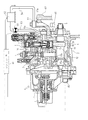
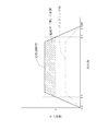
図1は本発明の一実施例に係る燃料噴射ポンプの全体的な構成を示した側面断面図、図2はプランジャ及びタペットの側面断面図、図3は燃料噴射ポンプのコントローラを示すブロック図、図4はカム位相角とカム速度との関係を示すグラフ図である。なお、本発明では図1の左右方向を燃料噴射ポンプ1の前後方向とし、図1の紙面上下方向を燃料噴射ポンプ1の上下方向とする。
Next, embodiments of the invention will be described.
1 is a side sectional view showing an overall configuration of a fuel injection pump according to an embodiment of the present invention, FIG. 2 is a side sectional view of a plunger and a tappet, and FIG. 3 is a block diagram showing a controller of the fuel injection pump. FIG. 4 is a graph showing the relationship between the cam phase angle and the cam speed. In the present invention, the left-right direction in FIG. 1 is the front-rear direction of the fuel injection pump 1, and the up-down direction in FIG.
図1、図2に示すように、燃料噴射ポンプ1は、ポンプハウジング2とハイドロリックヘッド3を上下に接合して構成されている。ポンプハウジング2の前側(図1における左側)には、エンジンの燃料噴射量を電気的に制御する電子ガバナ装置4が配設されており、ポンプハウジング2の後側には、ギヤケース67が配設されている。
As shown in FIGS. 1 and 2, the fuel injection pump 1 is configured by vertically joining a
前記ハイドロリックヘッド3には、プランジャバレル8が挿嵌されており、該プランジャバレル8内にプランジャ7が上下摺動自在に内装され、カムシャフト5に形成したカム6の回転により、タペット12を介してプランジャ7が上下摺動するように構成されている。
また、プランジャ7上方のプランジャバレル8内の空間には、燃料ギャラリ14より流入される燃料油をプランジャ7により圧縮する燃料圧室19が形成されている。
A
A
また、ポンプハウジング2において、カムシャフト5に形成されるカム6の上方、プランジャバレル8の下方には、上下方向に摺動孔15aが形成されており、該摺動孔15a内にタペット12とプランジャ7の下部とプランジャスプリング34と上部スプリング受け33とを収納し、該タペット12とプランジャバレル8との間、言い換えれば、タペット12の内側の空間をタペット室15として構成している。また、前記カム6は、ポンプハウジング2に形成されたカム室13に配設されている。該カム室13はタペット12の下方の外側の空間である。
In the
図1及び図2に示すように、前記タペット12は、タペット本体35とタペットピン37とタペットローラ11と下部スプリング受け31等を備える。前記タペット本体35は上方を開放した椀型に構成され、タペット本体35の底部内にタペットピン37を横架し、該タペットピン37にタペットローラ11が回転自在に軸支されている。該タペットローラ11が前記カム6の外周面に当接するように配設される。但し、タペット12はタペットローラ11及びタペットピン37を備えない構成とすることもできる。
As shown in FIGS. 1 and 2, the
前記タペット本体35の上部には下部スプリング受け31とリング36が収納される。該下部スプリング受け31は円板の中央に突部31bを上方に突出して形成され、該突部31bに前記プランジャ7の下端部が係止される。該下部スプリング受け31の突部31b周囲にプランジャスプリング34の下端部が嵌合されてタペット本体35の上方より挿入される。なお、タペット本体35と下部スプリング受け31は一体的に構成することも可能である。
前記リング36はタペットローラ11の上面が下部スプリング受け31に当接しないようにして、タペットローラ11がスムースに回転するようにするとともに、後述する気抜き孔32から潤滑油が容易に排出されるようにするためのものである。リング36は、タペット本体35でその底部と下部スプリング受け31との間に介在され、タペットローラ11と下部スプリング受け31との間に空間を形成する構成としている。
A
The
また、タペット12の上方に上部スプリング受け33が配設される。該上部スプリング受け33は筒状に形成され、その上端部でハイドロリックヘッド3に貫設されるとともに、前記プランジャバレル8の下部に外嵌される。前記上部スプリング受け33とプランジャバレル8の下部との間には、コントロールスリーブ41が回転自在に介在されている。
An
前記上部スプリング受け33の下端部では、内周部に下側が大径となる環状の段部が形成され、該段部にプランジャスプリング34の上端部が嵌入される。このような上部スプリング受け33と下部スプリング受け31との間にプランジャスプリング34が介装され、該プランジャスプリング34の付勢力により下部スプリング受け31が下方へ付勢され、ひいてはプランジャ7及びタペット12が下方へ付勢されている。
こうして、カム6が回転されることによりタペット12が摺動孔15a内を上下摺動し、同時にプランジャ7が上下動することになり、上方の燃料圧室19内に供給された燃料油が圧送されることになる。
At the lower end portion of the
Thus, when the cam 6 is rotated, the
次に、タペット12の下部スプリング受け31の構造について説明する。
前記下部スプリング受け31にはタペット12の内側と外側、つまり、タペット12を構成する下部スプリング受け31にはタペット室15とカム室13とを連通する気抜き孔32が設けられ、該気抜き孔32はプランジャスプリング34やプランジャ7等により塞がれない位置に配置される。該気抜き孔32は、タペット12が上下摺動する際に、タペット室15内とカム室13内の圧力差をなくすとともに、タペット室15内に溜まった潤滑油を抜くために設けられる孔である。
Next, the structure of the
The
次に前記タペット室15内の潤滑油を吸引するための構成について説明する。
前記タペット室15とポンプハウジング2外部とを連通するための連通孔51が穿設されている。言い換えれば、ポンプハウジング2の外側からタペット室15に向かって連通孔51が穿設されている。該連通孔51の外側端にはジョイント56を介して吸引手段となるバキュームポンプ52の吸入側と接続するための吸引通路53が設けられている。前記バキュームポンプ52は、例えば真空ポンプで構成されており、クランク軸から動力が伝達され、または、エンジン外部に設けられたモーター等のアクチュエータにより駆動され、前記タペット室15内の潤滑油を吸引するものである。
Next, a configuration for sucking the lubricating oil in the tappet chamber 15 will be described.
A communication hole 51 for communicating the tappet chamber 15 with the outside of the
また、前記吸引通路53の中途部には、電磁弁により構成された開閉弁60が設けられている。図1及び図3に示すように、前記開閉弁60のソレノイドは制御手段となるコントローラ61と接続され、該コントローラ61によって開閉弁60が開閉制御されており、バキュームポンプ52による吸引の入切を行うことが可能となっている。また、前記コントローラ61には、エンジン回転検知手段として、前記カムシャフト5の位相角を検知するための角度センサ65が接続されている。該角度センサ65は回転数センサも兼ねており、カムシャフト5の前側に配置している。該カムシャフト5は歯車等を介して図示せぬクランク軸と連動連結されており、前記角度センサ65は、前記カムシャフト5の位相角も同時に検知することができ、カム6の現在の位置を検知できるものである。これにより、タペット12の昇降位置を検知することが可能となっている。また、前記角度センサ65の検出値より前記カムシャフト5の回転数及びカム速度を演算することが可能であり、これにより、タペット12の上昇速度を知ることが可能となっている。なお、角度センサと回転数センサは別々に設けてそれぞれコントローラ61と接続することも可能である。
In the middle of the
そして、前記開閉弁60は、前記カム6が上昇行程にあるとき、すなわち図4のカムシャフト5の位相角がθ0からθTOPまでの間であって、かつ、カム6のカム速度が設定値となる設定速度V以上である場合にのみ開き、前記カムシャフト5の位相角がその他の位置及び設定速度V以下では閉じる構成とする。このように構成することにより、前記カム6が上昇行程にあり、かつ、例えば、図4の実線で示す定格運転時のように、カム6のカム速度が設定速度V以上の場合には、特に図示せぬ潤滑油ポンプからカム室13への潤滑油の吐出量が多くなり、潤滑油の飛沫も発生し易くなるため、タペット室15内に多く潤滑油が浸入することになるが、この浸入した潤滑油を前記バキュームポンプ52で発生する吸引力によって吸引することで、プランジャ7(燃料圧室19)側への混入が減少することになる。また、カム6が下降行程にあるときは燃料圧室19側へ潤滑油が混入することはなく、また、例えば図4の一点鎖線で示すアイドリング時のようにカム6のカム速度が設定速度V未満の時には、潤滑油ポンプからカム室13への潤滑油の吐出量が少なく、潤滑油がタペット室15内にあまり浸入しないので、前記開閉弁60を閉じることによって、バキュームポンプ52への吸引を停止する。このように構成することにより、常時吸引すると摺動孔15aへの潤滑油供給量が減少しすぎるので、潤滑油の過度の吸引を防止し、適度に潤滑してプランジャ7などの焼きつきを防止することができる。
When the cam 6 is in the upward stroke, that is, the phase angle of the
前記コントローラ61は電子ガバナ装置4の制御に供するコントローラと同一のコントローラを共用する構成とすることも可能である。このように構成することにより、コントローラを新たに付加する必要がなく、コストの削減を図ることができる。
The
前記バキュームポンプ52によって吸引された潤滑油は、前記バキュームポンプ52の吐出側に連設した戻し通路54を通ってギヤケース67内に排出される。つまり、前記戻し通路54の一端は、バキュームポンプ52の吐出側に接続され、他端は、前記ポンプハウジング2の外側に連設したギヤケース67の上部に形成したギヤケース側連通孔67aとジョイント57を介して接続している。これにより、前記戻し通路54を通って排出された潤滑油は、前記ギヤケース側連通孔67aを通りギヤケース67内に排出され、前記ギヤケース67から前記ポンプハウジング2内または図示せぬクランクケース内へと循環することとなる。また、ポンプハウジング2内またはクランクケース内が過度に負圧となることがない。
Lubricating oil sucked by the
また、前記ギヤケース側連通孔67aはギヤケース67内に配置したギヤ68の上方に設けている。複数のギヤが存在する場合には最も上部に位置するギヤ68の上方にギヤケース側連通孔67aを配置している。このように構成することにより、前記潤滑油がギヤケース67内に回収される際に、ギヤ68上に落ちることとなり、該ギヤ68に噛み合うギヤトレインを潤滑することができる。前記ギヤ68は潤滑油を充填したクランクケース内の油面よりも上方に位置するため、潤滑油を供給することが困難であった。そこで、前記ギヤケース側連通孔67aをギヤ68の上方に設けることにより、前記ギヤ68への潤滑油の供給を容易にしたものである。
The gear case
以上のように、前記燃料噴射ポンプ1は、プランジャ7の下部にタペット12を取り付け、該タペット12の下面にカム6を当接するように配置し、該カム6を回転させることにより前記プランジャ7を往復動させて燃料油を圧送する燃料噴射ポンプ1において、前記タペット12を収納するタペット室15と、該タペット室15が設けられるポンプハウジング2の外部とを連通する連通孔51を設け、前記連通孔51にバキュームポンプ52を接続したものである。このように構成することにより、バキュームポンプ52により、前記タペット室15内に浸入した潤滑油のうち、タペット室15内を浮遊する潤滑油の飛沫や余分な潤滑油を吸引して、強制的に排出することが可能となり、潤滑油がプランジャ7に付着して、プランジャ7とプランジャバレル8との隙間を通って燃料油に混入することを防止することができる。その結果、排気ガスに含まれる硫化物等を減少させることができる。
As described above, the fuel injection pump 1 has the
また、前記燃料噴射ポンプ1は、前記連通孔51とバキュームポンプ52とを繋ぐ吸引通路53に開閉弁60を設け、該開閉弁60と角度センサ65をコントローラ61と接続し、前記角度センサ65により前記カムの位相を検出し、設定した位相で前記開閉弁60を開閉するように制御したものである。このように構成することにより、バキュームポンプ52による潤滑油の吸引を、設定した位相の時にできるので、潤滑油の飛沫が多く発生する時に効率よく吸引でき、潤滑油の過剰な吸引を防止して焼きつきを防止できる。
The fuel injection pump 1 is provided with an opening / closing
また、前記開閉弁60は、前記位相がプランジャ7の上昇行程時であって、前記カム6のカム速度が設定速度V以上のときに開くように制御したものである。このように構成することにより、プランジャ7の上昇時かつ、カム速度が設定速度V以上の時のみ吸引するので、潤滑油の燃料圧室19側への混入を減少でき、始動時や低速回転時には開閉弁60を閉じて、過剰な潤滑油の吸引を防止してプランジャ7の焼きつきが起こるのを防止することができる。これにより燃料噴射ポンプ1の安定した運転が可能となり、燃料噴射ポンプ1の耐久性が向上する。
The on-off
また、前記燃料噴射ポンプ1は、前記バキュームポンプ52の吐出側に接続した戻し通路54の他端を、前記ポンプハウジング2に連設したギヤケース67に接続したものである。このように構成することにより、吸引した潤滑油をギヤケース67に戻すことで、エンジンのハウジング内の潤滑油の全体量を一定に保つことが可能となる。また、タペット室15側を常時負圧にすることがなく、エンジンのハウジングの内部圧力も均等に保つことができる。
Further, the fuel injection pump 1 has the other end of the
また、前記戻し通路54の他端の接続位置は、前記ギヤケース67内に収容したギヤ68の上方としたものである。このように構成することにより、ギヤケース67内に収容された潤滑油の油面よりも上方に位置するギヤ68に潤滑油を供給することが可能となり、吸引した潤滑油の有効利用が可能となる。
The connection position of the other end of the
1 燃料噴射ポンプ
2 ポンプハウジング
6 カム
7 プランジャ
12 タペット
13 カム室
15 タペット室
31 下部スプリング受け
32 気抜き孔
51 連通孔
52 バキュームポンプ
DESCRIPTION OF SYMBOLS 1 Fuel injection pump 2 Pump housing 6 Cam 7
Claims (5)
前記タペットを収納するタペット室と、該タペット室が設けられるポンプハウジングの外部とを連通する連通孔を設け、前記連通孔に吸引手段を接続した、
ことを特徴とする燃料噴射ポンプ。 In a fuel injection pump that attaches a tappet to the lower part of the plunger, arranges the cam so as to contact the lower surface of the tappet, and reciprocates the plunger by rotating the cam to pump fuel oil.
A tap hole that houses the tappet and a communication hole that communicates with the outside of the pump housing in which the tappet chamber is provided, and a suction means is connected to the communication hole;
A fuel injection pump characterized by that.
ことを特徴とする請求項1に記載の燃料噴射ポンプ。 An opening / closing valve is provided in the suction passage connecting the communication hole and the suction means, the opening / closing valve and the engine rotation detection means are connected to the control means, the phase of the cam is detected by the engine rotation detection means, and the set phase is set. Controlled to open and close the on-off valve,
The fuel injection pump according to claim 1.
ことを特徴とする請求項2に記載の燃料噴射ポンプ。 The on-off valve is controlled to open when the phase is during the upward stroke of the plunger and the cam speed of the cam is greater than or equal to a set value.
The fuel injection pump according to claim 2.
ことを特徴とする請求項1に記載の燃料噴射ポンプ。 The other end of the return passage connected to the discharge side of the suction means was connected to a gear case connected to the pump housing.
The fuel injection pump according to claim 1.
ことを特徴とする請求項4に記載の燃料噴射ポンプ。
The connection position of the other end of the return passage was above the gear accommodated in the gear case,
The fuel injection pump according to claim 4.
Priority Applications (1)
| Application Number | Priority Date | Filing Date | Title |
|---|---|---|---|
| JP2008127648A JP4700708B2 (en) | 2008-05-14 | 2008-05-14 | Fuel injection pump |
Applications Claiming Priority (1)
| Application Number | Priority Date | Filing Date | Title |
|---|---|---|---|
| JP2008127648A JP4700708B2 (en) | 2008-05-14 | 2008-05-14 | Fuel injection pump |
Publications (2)
| Publication Number | Publication Date |
|---|---|
| JP2009275601A JP2009275601A (en) | 2009-11-26 |
| JP4700708B2 true JP4700708B2 (en) | 2011-06-15 |
Family
ID=41441267
Family Applications (1)
| Application Number | Title | Priority Date | Filing Date |
|---|---|---|---|
| JP2008127648A Expired - Fee Related JP4700708B2 (en) | 2008-05-14 | 2008-05-14 | Fuel injection pump |
Country Status (1)
| Country | Link |
|---|---|
| JP (1) | JP4700708B2 (en) |
Citations (4)
| Publication number | Priority date | Publication date | Assignee | Title |
|---|---|---|---|---|
| JP2000064926A (en) * | 1998-07-03 | 2000-03-03 | Waertsilae Nsd Oy Ab | Integral pump and tappet device |
| JP2005146984A (en) * | 2003-11-14 | 2005-06-09 | Yanmar Co Ltd | Fuel injection pump |
| JP2007100712A (en) * | 2007-01-25 | 2007-04-19 | Bosch Corp | Dme fuel supply system for diesel engine |
| JP2008106780A (en) * | 2007-12-04 | 2008-05-08 | Yanmar Co Ltd | Fuel injection pump |
-
2008
- 2008-05-14 JP JP2008127648A patent/JP4700708B2/en not_active Expired - Fee Related
Patent Citations (4)
| Publication number | Priority date | Publication date | Assignee | Title |
|---|---|---|---|---|
| JP2000064926A (en) * | 1998-07-03 | 2000-03-03 | Waertsilae Nsd Oy Ab | Integral pump and tappet device |
| JP2005146984A (en) * | 2003-11-14 | 2005-06-09 | Yanmar Co Ltd | Fuel injection pump |
| JP2007100712A (en) * | 2007-01-25 | 2007-04-19 | Bosch Corp | Dme fuel supply system for diesel engine |
| JP2008106780A (en) * | 2007-12-04 | 2008-05-08 | Yanmar Co Ltd | Fuel injection pump |
Also Published As
| Publication number | Publication date |
|---|---|
| JP2009275601A (en) | 2009-11-26 |
Similar Documents
| Publication | Publication Date | Title |
|---|---|---|
| JP5320079B2 (en) | Fuel injection pump | |
| JP2007107688A (en) | Lubricating device | |
| JP2008106780A (en) | Fuel injection pump | |
| JP4700708B2 (en) | Fuel injection pump | |
| KR20150037505A (en) | Diesel Engine | |
| JP2007198311A (en) | Oil recovery device for internal combustion engine | |
| JP4139247B2 (en) | 4-cycle engine lubrication system | |
| JP4081429B2 (en) | Fuel injection pump | |
| JP2019215028A (en) | Oil strainer | |
| JP2009209800A (en) | Fuel injection pump | |
| JP2009275602A (en) | Fuel injection pump | |
| JP2017180171A (en) | Oil supply device of engine | |
| JP4963583B2 (en) | engine | |
| JP2019215027A (en) | Oil strainer | |
| JP5592519B2 (en) | Fuel injection pump | |
| JP2007321700A (en) | Engine lubricating device and engine | |
| JP2010196535A (en) | Pump | |
| JP2006291737A (en) | Oil pan and internal combustion engine provided with the same | |
| JP2012052460A (en) | Fuel injection pump | |
| JP2008215340A (en) | Supply pump | |
| KR100584215B1 (en) | small 4stroke engine | |
| KR100508182B1 (en) | Oil strainer | |
| JP2009275647A (en) | Bearing structure | |
| JP2000257529A (en) | Fuel injection pump | |
| JP2007064125A (en) | Oil supply device |
Legal Events
| Date | Code | Title | Description |
|---|---|---|---|
| A621 | Written request for application examination |
Free format text: JAPANESE INTERMEDIATE CODE: A621 Effective date: 20100301 |
|
| A977 | Report on retrieval |
Free format text: JAPANESE INTERMEDIATE CODE: A971007 Effective date: 20110228 |
|
| A01 | Written decision to grant a patent or to grant a registration (utility model) |
Free format text: JAPANESE INTERMEDIATE CODE: A01 Effective date: 20110301 |
|
| A61 | First payment of annual fees (during grant procedure) |
Free format text: JAPANESE INTERMEDIATE CODE: A61 Effective date: 20110304 |
|
| LAPS | Cancellation because of no payment of annual fees |