JP4700239B2 - Fall shock absorber for wheelchair - Google Patents
Fall shock absorber for wheelchair Download PDFInfo
- Publication number
- JP4700239B2 JP4700239B2 JP2001275348A JP2001275348A JP4700239B2 JP 4700239 B2 JP4700239 B2 JP 4700239B2 JP 2001275348 A JP2001275348 A JP 2001275348A JP 2001275348 A JP2001275348 A JP 2001275348A JP 4700239 B2 JP4700239 B2 JP 4700239B2
- Authority
- JP
- Japan
- Prior art keywords
- wheelchair
- bag
- air bag
- user
- bag portion
- Prior art date
- Legal status (The legal status is an assumption and is not a legal conclusion. Google has not performed a legal analysis and makes no representation as to the accuracy of the status listed.)
- Expired - Lifetime
Links
Images


Landscapes
- Air Bags (AREA)
Description
【0001】
【発明の属する技術分野】
本発明は、車椅子の転倒から人体を保護するための車椅子用転倒衝撃吸収装置に関するものである。
【0002】
【従来の技術】
従来、歩行の不自由な人が使用する車椅子としては、使用者または補助者の人力によって走行するものや、使用者の運転操作によって自走可能な電動のものなどが知られている。即ち、歩行の不自由な人であっても、車椅子の使用により、車椅子の走行可能な範囲であれば自由に移動することができる。
【0003】
【発明が解決しようとする課題】
しかしながら、車椅子の走行可能な範囲であっても、不慮の事故等によって車椅子が転倒する場合がある。このような場合、従来の車椅子には転倒時に使用者への衝撃を吸収する手段が設けられていないため、使用者の保護が十分でないという問題点があった。特に、車椅子の使用者は健常者に比べると俊敏に身を保護することができない場合が多いため、車椅子の転倒時に使用者を衝撃から保護する必要性が高まっている。
【0004】
本発明は前記問題点に鑑みてなされたものであり、その目的とするところは、車椅子の使用者に対する転倒時の衝撃を吸収することのできる車椅子用転倒衝撃吸収装置を提供することにある。
【0005】
【課題を解決するための手段】
本発明は前記目的を達成するために、請求項1では、膨張時に車椅子の使用者を覆う空気袋と、空気袋を膨張させる膨張手段とを備えた車椅子用転倒衝撃吸収装置において、前記空気袋を、車椅子の両側部にそれぞれ膨出する一対の第1袋部と、車椅子の後部に膨出する第2袋部と、車椅子の前部に膨出する第3袋部とから形成し、第3袋部を膨張時に一方の第1袋部側から他方の第1袋部に向かって膨出するように形成している。
【0006】
これにより、空気袋を膨張させると、車椅子の使用者が空気袋によって覆われることから、車椅子の使用者に対する転倒時の衝撃が空気袋によって吸収される。その際、使用者の両側方及び後方への衝撃が各第1袋部及び第2袋部によって吸収されるとともに、各第1袋部から膨出する第3袋部によって使用者の前方が覆われることから、各第3袋部によって使用者Aの前方への衝撃も吸収することができ、車椅子からの転落も防止される。
【0007】
また、請求項2では、請求項1記載の車椅子用転倒衝撃吸収装置において、前記第3袋部を各第1袋部側にそれぞれ少なくとも一つずつ設けている。
【0008】
これにより、請求項1の作用に加え、各第1袋部に少なくとも一つずつ設けられた計2つ以上の第3袋部によって使用者の前方が覆われる。
【0009】
また、請求項3では、請求項2記載の車椅子用転倒衝撃吸収装置において、前記各第1袋部にそれぞれ設けた第3袋部を互い違いにずらして配置している。
【0010】
これにより、請求項2の作用に加え、各第3袋部は互い違いにずらして配置されることから、膨出した各第3袋部が互いに干渉することがなく、各第3袋部をそれぞれ長く形成することが可能となる。
【0011】
また、請求項4では、請求項1、2または3記載の車椅子用転倒衝撃吸収装置において、前記車椅子の背面側及び両側面側に亘って形成され、収縮時の空気袋を収納する収納部を備えている。
【0012】
これにより、請求項1、2または3の作用に加え、空気袋の収納部が車椅子の背面側及び両側面側に亘って形成されているので、空気袋の各第1袋部及び第2袋部をそれぞれ収納部の両側面側及び背面側に収納することができる。また、第3袋部はそれぞれ一方または他方の第1袋部に設けられているため、各第1袋部と共に収納部の両側面側に収納することができる。
【0013】
【発明の実施の形態】
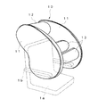
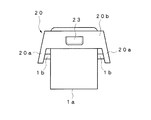
図1乃至図8は本発明の一実施形態を示すもので、図1は車椅子及び転倒衝撃吸収装置の側面図、図2は膨張状態の空気袋を示す斜視図、図3はその正面図、図4は制御系を示すブロック図、図5は空気袋を収納した状態を示す斜視図、図6はその背面図、図7は車椅子の前後方向の傾斜状態を示す部分側面図、図8は車椅子の左右方向の傾斜状態を示す部分正面図である。
【0014】
この転倒衝撃吸収装置は、車椅子1に設けられた空気袋10と、空気袋10を収納する収納カバー20と、空気袋10を膨張させる充気装置30と、車椅子1側から路面までの距離を検出する複数のセンサ40と、各センサ40の検出距離に基づいて車椅子1の傾斜を検知することにより空気袋10を膨張させる制御部50とから構成されている。
【0015】
空気袋10は、車椅子1の両側部にそれぞれ膨出する一対の第1袋部11と、車椅子1の後部に膨出する第2袋部12と、車椅子1の前部に膨出する計2つの第3袋部13とから形成され、気密性及び耐久性の高い生地によって縫製されている。各第1袋部11は、それぞれ車椅子1の右側及び左側において、車椅子1に腰掛けた使用者Aの上半身、その前方及び後方に対応する範囲まで膨張するように形成されている。第2袋部12は、車椅子1の後部上方において、使用者Aの後頭部の後方に円筒状に膨張するように形成され、その両端は各第1袋部11の後部上方に連通している。各第3袋部13は、車椅子1の前部において、それぞれ使用者Aの正面に円柱状に膨張するように形成され、その一端は第1袋部11の前部に連通している。この場合、一方の第3袋部13は一方の第1袋部11に設けられ、他方の第3袋部13は他方の第1袋部11に設けられている。また、各第3袋部13は互い違いにずらして配置され、膨張時に互いに先端側の一部が間隔をおいて上下に重なり合うようになっている。
【0016】
収納カバー20は車椅子1の椅子部分1aの背面側及び肘掛け部分1bに亘って形成され、固定ベルト21によって固定されている。この収納カバー20には収縮状態の空気袋10が折り畳まれて収納されるとともに、その上端部をスナップテープ等の結合具22によって閉鎖されており、空気袋10が膨張すると、結合具22が外れて空気袋10が収納カバー20から膨出するようになっている。即ち、空気袋10の各第1袋部11はそれぞれ収納カバー20の両側部20aに収納され、第2袋部12は収納カバー20の背面部20bに収納されている。また、各第3袋部13はそれぞれ一方または他方の第1袋部11に設けられているため、各第1袋部11と共に収納カバー20の両側部20aに収納されている。更に、収納カバー20の背面側には、図示しない制御ユニット等を収納するためのポケット23が設けられている。
【0017】
充気装置30は、ガスボンベに高圧ガスを封入した周知の構造からなり、そのガス吐出口は一方の第1袋部11に接続されている。即ち、充気装置30では、図示しない点火装置からの電気信号によって開放器の火薬を爆発させ、或いは撃針を突き刺すことにより、ガスボンベの吐出口を開放するようになっている。
【0018】
各センサ40は超音波センサや光センサ等、検出対象物からの距離を検出する周知の機器からなり、車椅子1の下面に前後及び左右の計4箇所にそれぞれ取付けられている。即ち、各センサ40は車椅子1が走行する路面までの距離をそれぞれ検出するようになっている。
【0019】
制御部50はマイクロコンピュータによって構成され、充気装置30及び各センサ40に接続されている。この制御部50では、前後各センサ40の検出距離の差または左右各センサ40の検出距離の差が所定距離以上になった場合、充気装置30を作動するようになっている。
【0020】
以上のように構成された転倒衝撃吸収装置においては、車椅子1が傾斜すると、車椅子1の傾斜が各センサ40によって検知され、これにより充気装置30が作動して空気袋10が膨張する。その際、空気袋10の膨張により収納カバー20の結合具22が外れ、空気袋10が膨出する。この場合、空気袋10の各第1袋部11によって使用者Aの両側方が覆われ、第2袋部12によって使用者Aの後頭部が覆われる。また、空気袋10の各第3袋部13がそれぞれ各第1袋部11から車椅子1の内側に膨出し、各第3袋部13によって使用者Aの前方が覆われる。これにより、車椅子1が転倒した場合でも、使用者Aへの転倒衝撃が空気袋10によって吸収されるとともに、各第3袋部13によって使用者Aが車椅子1側に保持される。
【0021】
また、制御部50では、図7に示すように車椅子1が前後方向に傾斜した場合、路面に対する前側のセンサ40と後側のセンサ40との検出距離の差L1 が所定距離以上になると空気袋10を膨張させるようになっている。また、図8に示すように車椅子1が左右方向に傾斜した場合には、路面に対する左側のセンサ40と右側のセンサ40との検出距離の差L2 が所定距離以上になると空気袋10を膨張させるようになっている。即ち、前側及び後側の各センサ40の検出距離の差と、左側及び右側の各センサ40の検出距離の差に基づいて車椅子1の傾斜を検知するようにしているので、車椅子1の前後及び左右方向の傾斜をそれぞれ検知することができ、何れの方向への転倒においても空気袋20を確実に膨張させることができる。
【0022】
このように、本実施形態の転倒衝撃吸収装置によれば、車椅子1の傾斜を検知すると、車椅子1に設けた空気袋10を膨張させ、空気袋10によって使用者Aを覆うようにしたので、車椅子1が転倒した場合でも、使用者Aへの衝撃を空気袋10で吸収することができる。従って、車椅子1の使用者Aを転倒事故から保護する場合に極めて有利である。その際、使用者Aの両側方及び後方への衝撃が各第1袋部11及び第2袋部12によって吸収されるとともに、各第1袋部11からそれぞれ車椅子1の内側に膨出する各第3袋部13によって使用者Aの前方が覆われることから、各第3袋部13によって使用者Aの前方への衝撃も吸収することができ、車椅子1からの転落も防止することができる。
【0023】
また、第3袋部13は各第1袋部11に一つずつ設けられているので、計2つの第3袋部13によって使用者Aへの衝撃の吸収及び転落の防止をより確実に行うことができる。この場合、各第3袋部13は互い違いにずらして配置されているので、膨出した各第3袋部13が互いに干渉することがない。これにより、各第3袋部13を互いに上下に重なり合うように長く形成することができ、衝撃吸収効果及び転落防止効果をより高めることができる。
【0024】
更に、収縮時の空気袋10を車椅子1側に設けた収納カバー20に収納するとともに、収納カバー20を車椅子1の背面側及び両側面側に亘って形成したので、空気袋10の各第1袋部11及び第2袋部12をそれぞれ収納カバー20の両側部20a及び背面部20bに収納することができるとともに、各第3袋部13はそれぞれ一方または他方の第1袋部11に設けられているため、各第1袋部11と共に収納カバー20の両側部20aに収納することができる。従って、空気袋10を車椅子1の乗り降りに支障を来すことなくコンパクトに収納することができ、実用化に際して極めて有利である。
【0025】
【発明の効果】
以上説明したように、請求項1の車椅子用転倒衝撃吸収装置によれば、車椅子が転倒した場合でも使用者への衝撃を空気袋によって吸収することができるので、車椅子の使用者を転倒事故から保護する場合に極めて有利である。その際、空気袋の各第1袋部及び第2袋部によって使用者の両側方及び後方への衝撃を吸収することができるとともに、第1袋部から膨出する第3袋部によって使用者の前方を覆うことができるので、第3袋部によって使用者の前方への衝撃も吸収することができ、車椅子からの転落も防止することができる。従って、車椅子の使用者をより効果的に転倒事故から保護することができる。
【0026】
また、請求項2の車椅子用転倒衝撃吸収装置によれば、請求項1の効果に加え、計2つ以上の第3袋部によって使用者への衝撃の吸収及び転落の防止をより確実に行うことができる。
【0027】
また、請求項3の車椅子用転倒衝撃吸収装置によれば、請求項2の効果に加え、各第1袋部に設けた第3袋部をそれぞれ長く形成することができるので、衝撃吸収効果及び転落防止効果をより高めることができる。
【0028】
また、請求項4の車椅子用転倒衝撃吸収装置によれば、請求項1、2または3の効果に加え、空気袋を車椅子の乗り降りに支障を来すことなくコンパクトに収納することができるので、実用化に際して極めて有利である。
【図面の簡単な説明】
【図1】本発明の一実施形態を示す車椅子及び転倒衝撃吸収装置の側面図
【図2】膨張状態の空気袋を示す斜視図
【図3】膨張状態の空気袋を示す正面図
【図4】制御系を示すブロック図
【図5】空気袋を収納した状態を示す斜視図
【図6】空気袋を収納した状態を示す背面図
【図7】車椅子の前後方向の傾斜状態を示す部分側面図
【図8】車椅子の左右方向の傾斜状態を示す部分正面図
【符号の説明】
1…車椅子、10…空気袋、11…第1袋部、12…第2袋部、13…第3袋部、20…収納カバー、30…充気装置、A…使用者。[0001]
BACKGROUND OF THE INVENTION
The present invention relates to a fall shock absorber for a wheelchair for protecting a human body from the fall of the wheelchair.
[0002]
[Prior art]
Conventionally, as a wheelchair used by a person who has difficulty in walking, a wheelchair that is driven by the power of a user or an assistant, an electric wheel that can be driven by a user's driving operation, and the like are known. That is, even a person who has difficulty in walking can move freely by using a wheelchair as long as the wheelchair can travel.
[0003]
[Problems to be solved by the invention]
However, even if the wheelchair can travel, the wheelchair may fall down due to an accident. In such a case, since the conventional wheelchair is not provided with means for absorbing the impact to the user at the time of falling, there is a problem that the user is not sufficiently protected. In particular, wheelchair users are often unable to protect themselves more quickly than healthy people, and there is an increasing need to protect users from impacts when a wheelchair falls.
[0004]
This invention is made | formed in view of the said problem, The place made into the objective is providing the fall impact-absorbing device for wheelchairs which can absorb the impact at the time of the fall with respect to the user of a wheelchair.
[0005]
[Means for Solving the Problems]
In order to achieve the above object, according to a first aspect of the present invention, in the fall shock absorber for a wheelchair comprising an air bag that covers a wheelchair user when inflated and an inflating means for inflating the air bag, the air bag is provided. Are formed from a pair of first bag portions that bulge on both sides of the wheelchair, a second bag portion that bulges on the rear portion of the wheelchair, and a third bag portion that bulges on the front portion of the wheelchair, The three bag portions are formed so as to bulge from one first bag portion side toward the other first bag portion when inflated.
[0006]
Thereby, when the air bag is inflated, the user of the wheelchair is covered with the air bag, so that the impact when the wheelchair user falls is absorbed by the air bag. At that time, the impact on both sides and the rear of the user is absorbed by the first bag portion and the second bag portion, and the front of the user is covered by the third bag portion bulging from each first bag portion. Therefore, the impact to the front of the user A can be absorbed by each third bag portion, and falling from the wheelchair is prevented.
[0007]
According to a second aspect of the present invention, in the wheelchair fall impact absorbing device according to the first aspect, at least one third bag portion is provided on each first bag portion side.
[0008]
Thereby, in addition to the effect | action of
[0009]
According to a third aspect of the present invention, in the wheelchair fall impact absorbing device according to the second aspect, the third bag portions provided in the first bag portions are staggered and arranged.
[0010]
Thereby, in addition to the operation of the second aspect, the third bag portions are arranged to be staggered so that the bulging third bag portions do not interfere with each other, It can be formed longer.
[0011]
Moreover, in Claim 4, in the fall shock absorber for wheelchairs of
[0012]
Thereby, in addition to the effect | action of
[0013]
DETAILED DESCRIPTION OF THE INVENTION
1 to 8 show an embodiment of the present invention, FIG. 1 is a side view of a wheelchair and a fall shock absorber, FIG. 2 is a perspective view showing an inflated air bag, and FIG. 3 is a front view thereof. 4 is a block diagram showing a control system, FIG. 5 is a perspective view showing a state in which an air bag is accommodated, FIG. 6 is a rear view thereof, FIG. 7 is a partial side view showing an inclined state of a wheelchair in the front-rear direction, and FIG. It is a partial front view which shows the inclination state of the left-right direction of a wheelchair.
[0014]
This overturning impact absorbing device includes an
[0015]
The
[0016]
The
[0017]
The
[0018]
Each
[0019]
The
[0020]
In the overturning impact absorbing device configured as described above, when the
[0021]
In addition, in the
[0022]
Thus, according to the overturning impact absorbing device of the present embodiment, when the inclination of the
[0023]
In addition, since one third bag portion 13 is provided for each first bag portion 11, a total of two third bag portions 13 can more reliably absorb the impact on the user A and prevent the fall. be able to. In this case, since the third bag portions 13 are staggered and arranged, the bulging third bag portions 13 do not interfere with each other. Thereby, each 3rd bag part 13 can be formed long so that it may mutually overlap, and an impact absorption effect and a fall prevention effect can be improved more.
[0024]
Furthermore, since the
[0025]
【The invention's effect】
As described above, according to the fall shock absorber for a wheelchair of
[0026]
Moreover, according to the fall impact absorbing device for a wheelchair of
[0027]
Moreover, according to the fall shock absorber for a wheelchair of
[0028]
Moreover, according to the fall shock absorber for a wheelchair of claim 4, in addition to the effect of
[Brief description of the drawings]
FIG. 1 is a side view of a wheelchair and a tipping shock absorber according to an embodiment of the present invention. FIG. 2 is a perspective view showing an inflated air bag. FIG. 3 is a front view showing an inflated air bag. FIG. 5 is a perspective view showing a state in which an air bag is housed. FIG. 6 is a rear view showing a state in which an air bag is housed. FIG. 7 is a partial side view showing an inclined state of a wheelchair in the front-rear direction. [Fig. 8] Partial front view showing the state of tilting the wheelchair in the left-right direction [Explanation of symbols]
DESCRIPTION OF
Claims (4)
前記空気袋を、車椅子の両側部にそれぞれ膨出する一対の第1袋部と、車椅子の後部に膨出する第2袋部と、車椅子の前部に膨出する第3袋部とから形成し、
第3袋部を膨張時に一方の第1袋部側から他方の第1袋部に向かって膨出するように形成した
ことを特徴とする車椅子用転倒衝撃吸収装置。In a wheelchair overturning shock absorbing device comprising an air bag covering a wheelchair user during inflating and an inflating means for inflating the air bag
The air bag is formed of a pair of first bag portions that bulge on both sides of the wheelchair, a second bag portion that bulges on the rear portion of the wheelchair, and a third bag portion that bulges on the front portion of the wheelchair. And
A fall shock absorber for a wheelchair characterized in that the third bag portion is formed so as to bulge from one first bag portion side toward the other first bag portion when inflated.
ことを特徴とする請求項1記載の車椅子用転倒衝撃吸収装置。2. The overturning shock absorbing device for wheelchair according to claim 1, wherein at least one third bag portion is provided on each first bag portion side.
ことを特徴とする請求項2記載の車椅子用転倒衝撃吸収装置。The fall shock absorber for a wheelchair according to claim 2, wherein the third bag portions respectively provided in the first bag portions are staggered and arranged.
ことを特徴とする請求項1、2または3記載の車椅子用転倒衝撃吸収装置。4. The overturning impact absorbing device for a wheelchair according to claim 1, further comprising a storage portion that is formed over a back surface side and both side surfaces of the wheelchair and stores an air bag when contracted.
Priority Applications (1)
| Application Number | Priority Date | Filing Date | Title |
|---|---|---|---|
| JP2001275348A JP4700239B2 (en) | 2001-09-11 | 2001-09-11 | Fall shock absorber for wheelchair |
Applications Claiming Priority (1)
| Application Number | Priority Date | Filing Date | Title |
|---|---|---|---|
| JP2001275348A JP4700239B2 (en) | 2001-09-11 | 2001-09-11 | Fall shock absorber for wheelchair |
Publications (2)
| Publication Number | Publication Date |
|---|---|
| JP2003079669A JP2003079669A (en) | 2003-03-18 |
| JP4700239B2 true JP4700239B2 (en) | 2011-06-15 |
Family
ID=19100223
Family Applications (1)
| Application Number | Title | Priority Date | Filing Date |
|---|---|---|---|
| JP2001275348A Expired - Lifetime JP4700239B2 (en) | 2001-09-11 | 2001-09-11 | Fall shock absorber for wheelchair |
Country Status (1)
| Country | Link |
|---|---|
| JP (1) | JP4700239B2 (en) |
Families Citing this family (5)
| Publication number | Priority date | Publication date | Assignee | Title |
|---|---|---|---|---|
| JP4252843B2 (en) * | 2003-05-22 | 2009-04-08 | 株式会社プロップ | wheelchair |
| JP4431417B2 (en) * | 2004-02-16 | 2010-03-17 | 株式会社プロップ | Wheelchair airbag device |
| JP4400495B2 (en) * | 2004-05-27 | 2010-01-20 | 豊田合成株式会社 | Side airbag device |
| JP2006151015A (en) * | 2004-11-25 | 2006-06-15 | Nippon Plast Co Ltd | Airbag device |
| JP2011067387A (en) * | 2009-09-25 | 2011-04-07 | Tadayoshi Sakurai | Wheelchair with disaster prevention hood |
Family Cites Families (6)
| Publication number | Priority date | Publication date | Assignee | Title |
|---|---|---|---|---|
| JPH0796049A (en) * | 1993-09-30 | 1995-04-11 | Hazama Gumi Ltd | Airbag system for a crash |
| JP3456754B2 (en) * | 1994-06-14 | 2003-10-14 | 本田技研工業株式会社 | How to deploy vehicle airbags |
| JP4210430B2 (en) * | 1997-11-04 | 2009-01-21 | デカ・プロダクツ・リミテッド・パートナーシップ | Cushion system for movable body |
| JPH11209086A (en) * | 1998-01-28 | 1999-08-03 | Mitsubishi Heavy Ind Ltd | Forklift truck |
| JPH11350213A (en) * | 1998-06-02 | 1999-12-21 | Takeshi Kageyama | Auxiliary tool for human body |
| JP2000177452A (en) * | 1998-12-17 | 2000-06-27 | Jiasu:Kk | Child's seat |
-
2001
- 2001-09-11 JP JP2001275348A patent/JP4700239B2/en not_active Expired - Lifetime
Also Published As
| Publication number | Publication date |
|---|---|
| JP2003079669A (en) | 2003-03-18 |
Similar Documents
| Publication | Publication Date | Title |
|---|---|---|
| JP3229950B2 (en) | Human body shock absorption aid | |
| US5310214A (en) | Air bag system for restraining movement of an adult and/or a child | |
| ES2270669A1 (en) | Airbag module for protection of the cervicodorsal region | |
| CN113200112B (en) | Scooter with safety device comprising inflatable liner | |
| KR101230437B1 (en) | The air vest which uses the acceleration sensor | |
| ES2252860T3 (en) | FREE EJECTION SEAT AND SAFETY GUARD FOR INDO-SKELETTIC SHOCK. | |
| BR0112562A (en) | Automatic inflatable vest | |
| JP4700239B2 (en) | Fall shock absorber for wheelchair | |
| JP5860442B2 (en) | Bicycle child seat and bicycle, and airbag module | |
| JP4769915B2 (en) | Fall shock absorber for wheelchair | |
| JP2016040171A (en) | Bicycle child seat and bicycle, and airbag module | |
| KR101510656B1 (en) | Vehicle for protecting occupant of vehicle | |
| KR101915409B1 (en) | An airbag device for an electric scooter and an electric scooter using the same | |
| CN117295430A (en) | protective device | |
| JP4252843B2 (en) | wheelchair | |
| KR20220086199A (en) | Autobicycle shield | |
| JP4431417B2 (en) | Wheelchair airbag device | |
| JP4624596B2 (en) | Fall shock absorber for wheelchair | |
| JP2011184015A (en) | Handstand wheel type moving body | |
| ES2226874T3 (en) | STEERING COLUMN AND DISPLACEMENT PROCEDURE FOR A STEERING COLUMN. | |
| ES2404171B2 (en) | Mandibular protection system for open type helmets | |
| JP2007111084A (en) | Air bag device for wheelchair | |
| JP2000279538A (en) | Drop impact absorption aid for human body | |
| JPH053054U (en) | Air bag system for vehicles | |
| JP2024531036A (en) | Head protection and cervical vertebrae protection airbags and manufacturing method thereof |
Legal Events
| Date | Code | Title | Description |
|---|---|---|---|
| A711 | Notification of change in applicant |
Free format text: JAPANESE INTERMEDIATE CODE: A711 Effective date: 20080822 |
|
| A621 | Written request for application examination |
Free format text: JAPANESE INTERMEDIATE CODE: A621 Effective date: 20080904 |
|
| A521 | Request for written amendment filed |
Free format text: JAPANESE INTERMEDIATE CODE: A821 Effective date: 20080822 |
|
| A521 | Request for written amendment filed |
Free format text: JAPANESE INTERMEDIATE CODE: A523 Effective date: 20081128 |
|
| TRDD | Decision of grant or rejection written | ||
| A01 | Written decision to grant a patent or to grant a registration (utility model) |
Free format text: JAPANESE INTERMEDIATE CODE: A01 Effective date: 20110209 |
|
| A977 | Report on retrieval |
Free format text: JAPANESE INTERMEDIATE CODE: A971007 Effective date: 20110217 |
|
| A61 | First payment of annual fees (during grant procedure) |
Free format text: JAPANESE INTERMEDIATE CODE: A61 Effective date: 20110304 |
|
| R150 | Certificate of patent or registration of utility model |
Ref document number: 4700239 Country of ref document: JP Free format text: JAPANESE INTERMEDIATE CODE: R150 |
|
| R250 | Receipt of annual fees |
Free format text: JAPANESE INTERMEDIATE CODE: R250 |
|
| R250 | Receipt of annual fees |
Free format text: JAPANESE INTERMEDIATE CODE: R250 |
|
| R250 | Receipt of annual fees |
Free format text: JAPANESE INTERMEDIATE CODE: R250 |
|
| R250 | Receipt of annual fees |
Free format text: JAPANESE INTERMEDIATE CODE: R250 |
|
| R250 | Receipt of annual fees |
Free format text: JAPANESE INTERMEDIATE CODE: R250 |
|
| R250 | Receipt of annual fees |
Free format text: JAPANESE INTERMEDIATE CODE: R250 |
|
| R250 | Receipt of annual fees |
Free format text: JAPANESE INTERMEDIATE CODE: R250 |
|
| R250 | Receipt of annual fees |
Free format text: JAPANESE INTERMEDIATE CODE: R250 |
|
| EXPY | Cancellation because of completion of term |