JP6029735B2 - Bicycle child seat and bicycle, and airbag module - Google Patents
Bicycle child seat and bicycle, and airbag module Download PDFInfo
- Publication number
- JP6029735B2 JP6029735B2 JP2015249626A JP2015249626A JP6029735B2 JP 6029735 B2 JP6029735 B2 JP 6029735B2 JP 2015249626 A JP2015249626 A JP 2015249626A JP 2015249626 A JP2015249626 A JP 2015249626A JP 6029735 B2 JP6029735 B2 JP 6029735B2
- Authority
- JP
- Japan
- Prior art keywords
- airbag
- bicycle
- child seat
- attached
- state
- Prior art date
- Legal status (The legal status is an assumption and is not a legal conclusion. Google has not performed a legal analysis and makes no representation as to the accuracy of the status listed.)
- Active
Links
- 238000001514 detection method Methods 0.000 claims description 40
- 230000004048 modification Effects 0.000 description 17
- 238000012986 modification Methods 0.000 description 17
- 230000001133 acceleration Effects 0.000 description 11
- 208000027418 Wounds and injury Diseases 0.000 description 2
- 238000005452 bending Methods 0.000 description 2
- 230000006378 damage Effects 0.000 description 2
- 238000010586 diagram Methods 0.000 description 2
- 238000006073 displacement reaction Methods 0.000 description 2
- 230000000694 effects Effects 0.000 description 2
- 238000005516 engineering process Methods 0.000 description 2
- 239000004744 fabric Substances 0.000 description 2
- 208000014674 injury Diseases 0.000 description 2
- 239000000463 material Substances 0.000 description 2
- HBBGRARXTFLTSG-UHFFFAOYSA-N Lithium ion Chemical compound [Li+] HBBGRARXTFLTSG-UHFFFAOYSA-N 0.000 description 1
- 238000007872 degassing Methods 0.000 description 1
- 230000006866 deterioration Effects 0.000 description 1
- 239000002360 explosive Substances 0.000 description 1
- 239000000446 fuel Substances 0.000 description 1
- 229910001416 lithium ion Inorganic materials 0.000 description 1
- 239000011347 resin Substances 0.000 description 1
- 229920005989 resin Polymers 0.000 description 1
Images


Description
本開示は、自転車用チャイルドシート、およびそれを備える自転車に関する。また、自転車用チャイルドシートに用いられるエアバッグモジュールに関する。 The present disclosure relates to a bicycle child seat and a bicycle including the same. The present invention also relates to an airbag module used for a bicycle child seat.
自転車において、幼い子供を同乗させる場合、自転車用チャイルドシートが利用される。自転車用チャイルドシートには、自転車の前輪上部に取り付けられるフロント用チャイルドシートや、後輪上部に取り付けられるリア用チャイルドシートがある。 In the case of a bicycle, a child seat for a bicycle is used when a young child rides on the bicycle. Bicycle child seats include a front child seat that is attached to the upper part of the front wheel of the bicycle and a rear child seat that is attached to the upper part of the rear wheel.
特許文献1には、3点式の安全ベルトを備えることで、同乗した子供の安全性を高めるようにした自転車用チャイルドシートが提案されている。しかしながら、安全ベルトを備えただけでは、転倒時において十分に子供を保護することが困難である。自転車の構造上、立ち歩き歩行、急な旋回、子供が揺れた際などに安定な走行をするのは困難であり、そのような場合、運転者が支えきれずに転倒してしまうおそれがある。特に、フロント用チャイルドシートとリア用チャイルドシートとを装着し、2人の子供を同乗させるなどして自転車の重量が普段よりも重くなった場合には、より転倒しやすくなる。また、電動アシスト自転車の場合にはさらに自転車の重量が重くなり、転倒しやすくなる。その結果として、子供が怪我をするおそれがある。
本開示の目的は、自転車転倒時の安全性を高めることができるようにした自転車用チャイルドシート、および自転車、ならびにエアバッグモジュールを提供することにある。 An object of the present disclosure is to provide a child seat for a bicycle, a bicycle, and an airbag module that can improve safety when the bicycle falls.
本開示による自転車用チャイルドシートは、自転車本体の傾斜状態を検出する傾斜センサと、自転車本体の前側に取り付けられ、背面から左右方向および前側方向に延在するように設けられた背もたれ部を有するチャイルドシート本体と、背もたれ部の左右方向から前側方向まで連続的に取り付けられ、傾斜センサの検出結果に応じて膨張するエアバッグとを備えたものである。 A child seat for a bicycle according to the present disclosure includes a tilt sensor that detects a tilt state of the bicycle main body , and a child seat main body that is attached to the front side of the bicycle main body and has a backrest portion that extends from the back side in the left-right direction and the front side direction. When continuously attached from lateral direction of the back portion to a front direction, in which a Rue airbag be inflated in accordance with the detection result of the inclination sensor.
本開示による自転車は、自転車本体と、自転車本体の傾斜状態を検出する傾斜センサと、自転車本体の前側に取り付けられ、背面から左右方向および前側方向に延在するように設けられた背もたれ部を有するチャイルドシート本体と、背もたれ部の左右方向から前側方向まで連続的に取り付けられ、傾斜センサの検出結果に応じて膨張するエアバッグとを備えたものである。 A bicycle according to the present disclosure includes a bicycle body, a tilt sensor that detects a tilt state of the bicycle body , and a backrest that is attached to the front side of the bicycle body and extends from the back side in the left-right direction and the front side direction. and the child seat body, a right-left direction of the back portion to a front direction is attached continuously, in which a Rue airbag be inflated in accordance with the detection result of the inclination sensor.
本開示によるエアバッグモジュールは、背面から左右方向および前側方向に延在するように設けられた背もたれ部を有する自転車用のチャイルドシート本体に取り付けられるエアバッグモジュールであって、エアバッグと、自転車本体の傾斜状態を示す検出信号に基づいて前記エアバッグを膨張させるインフレータとを備え、前記チャイルドシート本体の背もたれ部の左右方向から前側方向まで連続的に取り付けられるようにしたものである。 An airbag module according to the present disclosure is an airbag module that is attached to a child seat body for a bicycle having a backrest portion that is provided so as to extend from the back side in the left-right direction and the front side direction . And an inflator that inflates the airbag based on a detection signal indicating an inclined state, and is continuously attached from the left-right direction to the front-side direction of the backrest portion of the child seat body.
本開示による自転車用チャイルドシート、自転車、またはエアバッグモジュールでは、チャイルドシート本体の背もたれ部の左右方向から前側方向まで連続的に取り付けられたエアバッグが、自転車本体の傾斜状態に応じて展開する。 In the bicycle child seat, the bicycle, or the airbag module according to the present disclosure, the airbag continuously attached from the left-right direction to the front direction of the backrest portion of the child seat body is deployed according to the tilted state of the bicycle body.
本開示の自転車用チャイルドシート、自転車、またはエアバッグモジュールによれば、チャイルドシート本体の背もたれ部の左右方向から前側方向まで連続的に取り付けられたエアバッグが、自転車本体の傾斜状態に応じて展開するようにしたので、自転車転倒時の安全性を高めることができる。
According to the bicycle child seat, the bicycle, or the airbag module of the present disclosure, the airbag that is continuously attached from the left-right direction to the front direction of the backrest portion of the child seat body is deployed according to the inclination state of the bicycle body. As a result, it is possible to improve safety when the bicycle falls.
以下、本開示の実施の形態について図面を参照して詳細に説明する。なお、説明は以下の順序で行う。
1.構成
1.1 自転車の全体構成
1.2 リア用チャイルドシートの構成
1.3 フロント用チャイルドシートの構成
1.4 エアバッグの詳細な構成
1.5 制御系の構成
2.動作
3.効果
4.変形例
Hereinafter, embodiments of the present disclosure will be described in detail with reference to the drawings. The description will be given in the following order.
1. 1. Configuration 1.1 Overall configuration of bicycle 1.2 Configuration of rear child seat 1.3 Configuration of front child seat 1.4 Detailed configuration of airbag 1.5 Configuration of
[1.構成]
(1.1 自転車の全体構成)
図1は、本開示の一実施の形態に係る自転車の全体構成の一例を示している。この自転車は、自転車本体1と、自転車本体1に取り付けられるフロント用チャイルドシート2およびリア用チャイルドシート3とを備えている。自転車本体1は、前輪4と、後輪5と、サドル6と、荷台7と、ハンドルバー8と、フロントフォーク9と、シートチューブ10と、ダウンチューブ11と、電動アシスト電源部12とを有している。
[1. Constitution]
(1.1 Overall configuration of bicycle)
FIG. 1 shows an example of the overall configuration of a bicycle according to an embodiment of the present disclosure. This bicycle includes a
この自転車はまた、走行をアシストするための駆動機構を備えている。電動アシスト電源部12は、その駆動機構を駆動するための電力を供給するものであり、例えば燃料電池またはリチウムイオン電池等を含んでいる。なお、本実施の形態では電動アシスト機能を有する自転車を例にして説明するが、本開示による技術は電動アシスト機能を持たない通常の自転車にも適用可能である。 This bicycle is also provided with a drive mechanism for assisting travel. The electric assist power supply unit 12 supplies electric power for driving the drive mechanism, and includes, for example, a fuel cell or a lithium ion battery. In the present embodiment, a bicycle having an electric assist function will be described as an example. However, the technology according to the present disclosure can be applied to a normal bicycle that does not have an electric assist function.
フロント用チャイルドシート2は、サドル6よりも前側において、前輪4の上部に取り付けられている。リア用チャイルドシート3は、サドル6よりも後ろ側において、後輪5および荷台7の上部に取り付けられている。フロント用チャイルドシート2およびリア用チャイルドシート3は、自転車本体1に対して着脱可能であってもよい。
The
(1.2 リア用チャイルドシートの構成)
図2は、リア用チャイルドシート3の本体の一構成例を示している。リア用チャイルドシート3の本体は、ヘッドレスト部71と、背もたれ部72と、フットレスト部73とを有している。ヘッドレスト部71、背もたれ部72、およびフットレスト部73は例えば、一体的な構成とされている。リア用チャイルドシート3の本体の前側には、取手部74が取り付けられている。
(1.2 Rear child seat configuration)
FIG. 2 shows a configuration example of the main body of the
リア用チャイルドシート3の本体の左側部分において少なくとも背もたれ部72に対応する側方領域には、第1のエアバッグとして、左側エアバッグ50Lが取り付けられている。図2の構成例では、左側エアバッグ50Lが、リア用チャイルドシート3の本体の背面(外側)付近の左側部分において、ヘッドレスト部71、背もたれ部72、およびフットレスト部73に対応する側方領域の全体に亘って取り付けられている。左側エアバッグ50Lは、チャイルドシート本体に対して着脱可能(交換可能)であってもよい。
In the left side portion of the main body of the
リア用チャイルドシート3の本体の右側部分において少なくとも背もたれ部72に対応する側方領域には、第2のエアバッグとして、右側エアバッグ50Rが取り付けられている。図2の構成例では、右側エアバッグ50Rが、リア用チャイルドシート3の本体の背面(外側)付近の右側部分において、ヘッドレスト部71、背もたれ部72、およびフットレスト部73に対応する側方領域の全体に亘って取り付けられている。右側エアバッグ50Rは、チャイルドシート本体に対して着脱可能(交換可能)であってもよい。
A
左側エアバッグ50Lおよび右側エアバッグ50Rはそれぞれ、後述する傾斜センサ21(図4)の検出結果に応じて独立して展開、膨張するようになっている。より具体的には、後述する傾斜センサ21(図4)によって検出された傾斜方向に応じて、左側エアバッグ50Lおよび右側エアバッグ50Rのいずれか一方のみが膨張するようになっている。例えば右側方向への傾斜が検出された場合には、右側エアバッグ50Rが膨張するようになっている。
The
図5は、リア用チャイルドシート3におけるエアバッグの展開状態の一例を示している。左側エアバッグ50Lおよび右側エアバッグ50Rはそれぞれ、リア用チャイルドシート3の本体に着座した子供15の頭部から足部までを側方から覆うように展開するようになっている。なお、図5では、右側エアバッグ50Rを展開した状態の一例を示しているが、左側エアバッグ50Lについても同様の展開状態となる。
FIG. 5 shows an example of an airbag deployed state in the
(1.3 フロント用チャイルドシートの構成)
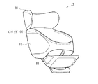
図3は、フロント用チャイルドシート2の本体の一構成例を示している。フロント用チャイルドシート2の本体は、ヘッドレスト部81と、背もたれ部82と、フットレスト部83とを有している。ヘッドレスト部81およびフットレスト部83は例えば、背もたれ部82に対して、位置を調整可能な構成とされている。
(1.3 Configuration of front child seat)
FIG. 3 shows a configuration example of the main body of the
フロント用チャイルドシート2の本体の左側部分において少なくとも背もたれ部82に対応する側方領域には、第1のエアバッグとして、左側エアバッグ60Lが取り付けられている。図3の構成例では、左側エアバッグ60Lが、フロント用チャイルドシート2の本体の外側の左側部分において、背もたれ部82に対応する側方領域に取り付けられている。左側エアバッグ60Lは、チャイルドシート本体に対して着脱可能(交換可能)であってもよい。
A
フロント用チャイルドシート2の本体の右側部分において少なくとも背もたれ部82に対応する側方領域には、第2のエアバッグとして、右側エアバッグ60Rが取り付けられている。図3の構成例では、右側エアバッグ60Rが、フロント用チャイルドシート2の本体の外側の右側部分において、背もたれ部82に対応する側方領域に取り付けられている。右側エアバッグ60Rは、チャイルドシート本体に対して着脱可能(交換可能)であってもよい。
A right airbag 60 </ b> R is attached as a second airbag to at least a side region corresponding to the
左側エアバッグ60Lおよび右側エアバッグ60Rはそれぞれ、リア用チャイルドシート3における左側エアバッグ50Lおよび右側エアバッグ50Rと同様に、後述する傾斜センサ21(図4)の検出結果に応じて独立して展開、膨張するようになっている。より具体的には、後述する傾斜センサ21(図4)によって検出された傾斜方向に応じて、左側エアバッグ60Lおよび右側エアバッグ60Rのいずれか一方のみが膨張するようになっている。例えば右側方向への傾斜が検出された場合には、右側エアバッグ60Rが膨張するようになっている。
The
図6は、フロント用チャイルドシート2におけるエアバッグの展開状態の一例を示している。左側エアバッグ60Lおよび右側エアバッグ60Rはそれぞれ、フロント用チャイルドシート2の本体に着座した子供15の、少なくとも頭部および胴部を側方から覆うように展開するようになっている。なお、図6では、右側エアバッグ60Rを展開した状態の一例を示しているが、左側エアバッグ60Lについても同様の展開状態となる。
FIG. 6 shows an example of an airbag deployed state in the
(1.4 エアバッグの詳細な構成)
以下、図7〜図12を参照して、リア用チャイルドシート3に取り付けられるエアバッグを例に詳細な構成を説明するが、フロント用チャイルドシート2に取り付けられるエアバッグに対しても適宜、同様の構成を適用可能である。
(1.4 Detailed configuration of airbag)
Hereinafter, with reference to FIGS. 7 to 12, a detailed configuration will be described by taking an airbag attached to the
図7は、リア用チャイルドシート3におけるエアバッグの展開状態の第1の例を背面側の構造と共に示している。なお、図7では、左側エアバッグ50Lを展開した状態の一例を示しているが、右側エアバッグ50Rについても同様の展開状態となる。
FIG. 7 shows a first example of the deployed state of the airbag in the
リア用チャイルドシート3の背面側には、後述する制御部40(図4)が取り付けられていてもよい。また、リア用チャイルドシート3の背面側の最上部には、後述する傾斜センサ21(図4)が取り付けられていてもよい。傾斜センサ21を上部に設けることにより、傾斜状態を検出しやすくなる。リア用チャイルドシート3の背面側にはまた、左側用エアボンベ33L,34Lと、右側用エアボンベ33R,34Rとが取り付けられていてもよい。リア用チャイルドシート3の背面側にはまた、制御部40等に電力を供給するための電源部が取り付けられていてもよい。ただし、制御部40等への電力を電動アシスト電源部12(図1)から供給するようにしてもよい。左側用エアボンベ33L,34Lと右側用エアボンベ33R,34Rはそれぞれ、リア用チャイルドシート3の本体に対して着脱可能(交換可能)であってもよい。
A control unit 40 (FIG. 4), which will be described later, may be attached to the rear side of the
左側用エアボンベ33L,34Lは、左側エアバッグ50Lを膨張させるためのガスGを供給する第1のインフレータである。左側用エアボンベ33L,34Lはそれぞれ異なる部位から左側エアバッグ50Lに対してガスGを供給するようになっている。より具体的には、左側用エアボンベ33Lは、左側エアバッグ50Lにおける上部51Lに取り付けられ、上部51Lから左側エアバッグ50Lのバッグ室56にガスGを供給するようになっている。左側用エアボンベ34Lは、左側エアバッグ50Lにおける下部52Lに取り付けられ、下部52Lから左側エアバッグ50Lのバッグ室56にガスGを供給するようになっている。
The
右側用エアボンベ33R,34Rは、右側エアバッグ50Rを膨張させるためのガスGを供給する第2のインフレータである。右側用エアボンベ33R,34Rはそれぞれ異なる部位から左側エアバッグ50Rに対してガスGを供給するようになっている。より具体的には、左側用エアボンベ33Rは、右側エアバッグ50Rにおける上部51Rに取り付けられ、上部51Rから右側エアバッグ50Rのバッグ室56にガスGを供給するようになっている。右側用エアボンベ34Rは、左側エアバッグ50Rにおける下部52Rに取り付けられ、下部52Rから右側エアバッグ50Rのバッグ室56にガスGを供給するようになっている。
The
このように、左側エアバッグ50Lおよび右側エアバッグ50Rのそれぞれにおいて、複数のボンベによって異なる部位からガスGを供給することによって、エアバッグの展開速度を高めることができる。
In this way, in each of the
左側用エアボンベ33L,34Lおよび右側用エアボンベ33R,34Rはそれぞれ、例えば電磁弁を有するCO2ボンベで構成することが好ましい。電磁弁を有するCO2ボンベで構成することにより、火薬を用いたボンベに比べて、展開時にエアバッグが子供に接触した際の怪我を防ぐことができると共に、動作時の音が軽減されるので、安全性を高めることができる。また、自転車転倒時に子供15をリラックスさせるために、アロマ付きのガスGを供給するようにしてもよい。また、アロマを発生する装置を別途、設けるようにしてもよい。
Each of the
左側エアバッグ60Lおよび右側エアバッグ60Rはそれぞれ、防水性の高い布や樹脂製の収納容器内に収納されていることが望ましい。エアバッグの素材自体も、防水性の高い布で構成されていることが望ましい。収納容器には例えばビスロンファスナ等を設けて、エアバッグを容易に展開可能にすることが望ましい。
Each of the
左側エアバッグ60Lおよび右側エアバッグ60Rはそれぞれ、地面との衝突やけがを防止するクッションの役目を果たすため、展開時に自動的にガスGを排出するようなベントは設けずに、展開後の形状をそのまま維持することが望ましい。代わりに、展開後のガス抜きを手動で行うためのボタン等を設けたり、取り外して空気を抜くことが望ましい。
Each of the
図8は、リア用チャイルドシート3におけるエアバッグの展開状態の第2の例を背面側の構造と共に示している。図7では、上部から下部までバッグ室56を単一の構成にしているが、図8に示したようにバッグ室56をバッグ室上部56Aと、バッグ室下部56Bとに分割された構成にしてもよい。バッグ室上部56Aとバッグ室下部56Bは、完全に分離されていてもよいし、バッグ室上部56Aとバッグ室下部56Bとを相互にガスGが行き来できるような連結部を有していてもよい。この場合、左側用エアボンベ33Lは、左側エアバッグ50Lにおける上部51Lに取り付けられ、バッグ室上部56AにガスGを供給する。左側用エアボンベ34Lは、左側エアバッグ50Lにおける下部52Lに取り付けられ、バッグ室下部56BにガスGを供給する。右側エアバッグ50Rについても同様である。
FIG. 8 shows a second example of the deployed state of the airbag in the
左側エアバッグ50Lおよび右側エアバッグ50Rはそれぞれ、リア用チャイルドシート3の本体に対して外側に向かった後、内側に向かうように展開するようになっている。このような展開をさせるための構造を図9および図11を参照して説明する。
Each of the
図9は、リア用チャイルドシート3におけるエアバッグの内側部分の構造の第1の例を示している。なお、図9では、右側エアバッグ50Rを展開した状態の一例を示しているが、左側エアバッグ50Lについても同様の構造および展開状態となる。図11は、リア用チャイルドシート3におけるエアバッグの展開状態を上部から見た一例を示している。なお、図11では、説明のために右側エアバッグ50Rおよび左側エアバッグ50Lの両方を展開した状態で示しているが、実際には同時に展開されるのは、いずれか一方のエアバッグのみである。
FIG. 9 shows a first example of the structure of the inner portion of the airbag in the
左側エアバッグ50Lは、図11に示したように、リア用チャイルドシート3の本体に対して一旦、外側方向XL1に向かった後、内側方向XL2に向かうように展開するようになっている。これにより、左側への自転車転倒時に子供15を左側から安全に包み込むように保護することが可能となる。このため、左側エアバッグ50Lは、展開した形状が、リア用チャイルドシート3の本体に対して内側に屈曲していることが好ましい。また、左側エアバッグ50Lには紐状部材53Lが取り付けられていることが好ましい。紐状部材53Lは、一端が左側エアバッグ50Lが展開した状態における左側エアバッグ50Lの内側部分に取り付けられ、左側エアバッグ50Lをリア用チャイルドシート3の本体に対して内側に引っ張るための第1の紐状部材である。紐状部材53Lは、図9に示したように、左側エアバッグ50Lの内側の上部から下部に亘って、複数設けられていることが好ましい。紐状部材53Lは、伸縮性のあるゴム状のものであってもよい。
As shown in FIG. 11, the left airbag 50 </ b> L is deployed with respect to the main body of the
右側エアバッグ50Rも同様に、図11に示したように、リア用チャイルドシート3の本体に対して一旦、外側方向XR1に向かった後、内側方向XR2に向かうように展開するようになっている。これにより、右側への自転車転倒時に子供15を右側から安全に包み込むように保護することが可能となる。このため、右側エアバッグ50Rは、展開した形状が、リア用チャイルドシート3の本体に対して内側に屈曲していることが好ましい。また、右側エアバッグ50Rには紐状部材53Rが取り付けられていることが好ましい。紐状部材53Rは、一端が右側エアバッグ50Rが展開した状態における右側エアバッグ50Rの内側部分に取り付けられ、右側エアバッグ50Rをリア用チャイルドシート3の本体に対して内側に引っ張るための第2の紐状部材である。紐状部材53Rは、紐状部材53Lと同様に、右側エアバッグ50Rの内側の上部から下部に亘って、複数設けられていることが好ましい。紐状部材53Rは、伸縮性のあるゴム状のものであってもよい。
Similarly, as shown in FIG. 11, the right airbag 50 </ b> R is once deployed in the outer direction XR <b> 1 and then deployed in the inner direction XR <b> 2 with respect to the main body of the
また、左側エアバッグ50Lおよび右側エアバッグ50Rはそれぞれ、図11の下段に示したように、展開した状態において、リア用チャイルドシート3の本体側の付け根部分の厚みt1を小さくし、中央部の厚みt2を大きくすることが好ましい。自転車転倒時に付け根部分が地面等に接触するとエアバッグの破裂等の原因となるおそれがあるが、付け根部分の厚みt1を小さくすることにより、それを防止することができる。
Further, as shown in the lower part of FIG. 11, each of the
図10は、リア用チャイルドシート3におけるエアバッグの内側部分の構造の第2の例を示している。なお、図10では、右側エアバッグ50Rを展開した状態の一例を示しているが、左側エアバッグ50Lについても同様の構造および展開状態となる。
FIG. 10 shows a second example of the structure of the inner portion of the airbag in the
左側エアバッグ50Lおよび右側エアバッグ50Rはそれぞれ、展開した状態において、内側部分の形状が、子供15の少なくとも頭部および胴部を収容するような凹部54を有していることが望ましい。これにより、自転車転倒時に子供15が外に投げ出されることを防止することができる。
It is desirable that the
また。左側エアバッグ50Lおよび右側エアバッグ50Rはそれぞれ、リア用チャイルドシート3の本体の下方から上方に行くに従い厚みが大きくなる展開形状を有していることが望ましい。図10に示したように、上部の厚みta、中部の厚みtb、下部の厚みtcが、ta>tb>tcとなるような逆三角形の展開形状を有していることが望ましい。これにより、自転車転倒時における子供15の頭部側の安全性をより高めることができる。
Also. Each of the
図12は、エアバッグの内側部分の表面構造の一例を示している。左側エアバッグ50Lおよび右側エアバッグ50Rの内側部分の表面には、自転車転倒時における衝撃を緩和するために、複数の凸部55が設けられていることが好ましい。また、エアバッグの外側部分が、転倒時に地面に当たっても損傷しないように、外側部分の素材を内側部分に比べて丈夫な素材にすることが好ましい。
FIG. 12 shows an example of the surface structure of the inner part of the airbag. It is preferable that a plurality of convex portions 55 are provided on the surfaces of the inner portions of the
(1.5 制御系の構成)
図4は、この自転車における制御系の一構成例を示している。この自転車は、車両状態検知部20と、インフレータ32と、制御部40と、操作部41と、音声出力部42と、表示部43と、着座状態検知部44と、電力供給部45と、カメラ部46とを備えている。車両状態検知部20は、傾斜センサ21と、加速度センサ22と、重量センサ23とを有している。その他、GPS、変位センサ、角速度センサ、地磁気センサ、およびジャイロセンサ等をさらに備えてもよい。
(1.5 Control system configuration)
FIG. 4 shows a configuration example of a control system in this bicycle. The bicycle includes a vehicle
インフレータ32は、エアバッグ31を膨張させるためのものである。なお、図4では、リア用チャイルドシート3に取り付けられる左側エアバッグ50Lおよび右側エアバッグ50Rと、フロント用チャイルドシート2に取り付けられる左側エアバッグ60Lおよび右側エアバッグ60Rとのそれぞれを総称して、エアバッグ31としている。また、左側エアバッグ50Lおよび右側エアバッグ50Rと、左側エアバッグ60Lおよび右側エアバッグ60Rとを膨張させるためのそれぞれのインフレータを総称して、インフレータ32としている。
The inflator 32 is for inflating the
エアバッグ31とインフレータ32は、例えば同一の収納容器内で一体化されて、1つのエアバッグモジュール30を構成していてもよい。例えば、図7における左側エアバッグ(第1のエアバッグ)50Lと、左側用エアボンベ(第1のインフレータ)33L,34Lとが同一の収納容器内で一体化されて、第1のエアバッグモジュールを構成していてもよい。また、図7における右側エアバッグ(第2のエアバッグ)50Rと、右側用エアボンベ(第2のインフレータ)33R,34Rとが同一の収納容器内で一体化されて、第2のエアバッグモジュールを構成していてもよい。例えば、衝撃などで外れたり、雨風等での劣化を防ぐため等、エアバッグ31が収納されているケースの中にインフレータ32としてCO2ボンベが入っていてもよい。
The
操作部41は、使用者が各部の動作を指定するためのものである。操作部41からは例えば、エアバッグ31を動作させるか否かを手動でオン/オフ操作することが可能となっている。操作部41からはまた、エアバッグ31を動作させるための条件等を指定することが可能となっている。例えばエアバッグ31を動作させるための条件として、傾斜センサ21に加えて加速度センサ22等の他のセンサの検出結果を考慮するか否かの条件等を指定することが可能となっている。
The operation unit 41 is for the user to specify the operation of each unit. From the operation unit 41, for example, it is possible to manually turn on / off whether or not to operate the
車両状態検知部20は、自転車本体1の傾斜状態や走行速度等を検出するためのものである。加速度センサ22は例えば、自転車走行時の旋回速度や自転車転倒時の転倒速度等を検出するためのものである。重量センサ23は例えば、自転車の乗員の重量を検出するたのめのものである。傾斜センサ21は、自転車本体1の傾斜状態を検出するたのめのものである。傾斜センサ21は、少なくとも自転車本体1の左右方向の傾斜状態を検出するようになっている。
The vehicle
車両状態検知部20はその他、GPSによって自転車の位置等を検出する機能を有していてもよい。また、変位センサによって自転車本体1の地面からの位置等を検出する機能を有していてもよい。
In addition, the vehicle
着座状態検知部44は、フロント用チャイルドシート2またはリア用チャイルドシート3における子供15の着座状態(着座しているか否か)を検知するものである。着座状態検知部44はまた、自転車本体1への着座状態(着座しているか否か)を検知する機能を有していてもよい。
The seating
音声出力部42は、車両状態検知部20の検出結果に応じた警報音等を発するものである。音声出力部42は例えば、傾斜センサ21の検出結果に応じて、自転車本体1が転倒しそうな危険な傾斜状態になった場合に警報音を発するようになっている。また、音声出力部42は例えば、加速度センサ22の検出結果に応じて、自転車走行時に急な旋回がなされた場合に「急な旋回は危険です」等の音声を発するようになっている。
The
表示部43は、各部の動作状態やセンサの設定状態等を表示したり、車両状態検知部20の検出結果に応じた警告表示等を行うものである。表示部43は例えば、傾斜センサ21の検出結果に応じて、自転車本体1が転倒しそうな危険な傾斜状態になった場合に警告表示をしたり、加速度センサ22の検出結果に応じて、自転車走行時に急な旋回がなされた場合に「急な旋回は危険です」等の警告表示をするようになっている。
The
電力供給部45は、各部に電力を供給するための電源部である。電力供給部45としては、電動アシスト電源部12(図1)を用いるようにしてもよい。
The
カメラ部46は、例えば周囲の環境を検出するためのものである。カメラ部46は例えば、周囲の環境が通常の道路であるか駐輪場であるか等を検出し、転倒時におけるエアバッグの展開を制御するために利用可能である。
The
制御部40は、制御系の各部の動作制御を行うものである。制御部40はまた、車両状態検知部20等の検出結果に応じて、インフレータ32を制御し、エアバッグ31の展開状態を制御するようになっている。
The
[2.動作]
この自転車では、制御部40によって、車両状態検知部20等の検出結果に応じて、インフレータ32が制御され、エアバッグ31の展開状態が制御される。制御部40は例えば、傾斜センサ21によって検出された傾斜方向に応じて、リア用チャイルドシート3における左側エアバッグ50Lおよび右側エアバッグ50Rのいずれか一方のみを膨張させるようにインフレータ32を制御する。例えば右側方向への傾斜が検出された場合には、右側エアバッグ50Rが膨張するようにインフレータ32を制御する。
[2. Operation]
In this bicycle, the
制御部40はまた、エアバッグ31を動作させるための条件として、傾斜センサ21に加えて加速度センサ22等の他のセンサの検出結果を考慮するようにしてもよい。例えば、傾斜センサ21に加えて加速度センサ22の検出結果に基づいて、転倒時の加速度に応じてエアバッグ31を動作させるような制御を行ってもよい。例えば緩やかな加速による転倒時にはエアバッグ31を動作させずに、急な加速による転倒時にのみエアバッグ31を動作させるような制御を行ってもよい。制御部40はまた、カメラ部46の検出結果を考慮するようにしてもよい。例えば周囲の環境が通常の道路ではな駐輪場である場合にはエアバッグ31を動作させないような制御を行ってもよい。
The
制御部40はまた、所定の条件が一定時間続いた場合には、傾斜センサ22の検出結果に関わらず、エアバッグ31を膨張させないような制御を行うようにしてもよい。例えば、所定の条件として、着座状態検知部44の検出結果に基づいて、子供15が着座していない状態が一定時間続いたと判断される場合には、傾斜センサ21の検出結果に関わらず、エアバッグ31を膨張させないような制御を行うようにしてもよい。そのほか、例えば、自転車が左側に転倒してリア用チャイルドシート3における左側エアバッグ50Lを膨張させた場合には、その後、無駄に右側エアバッグ50Rを膨張させないような制御を行うようにしてもよい。
The
[3.効果]
以上のように、本実施の形態によれば、チャイルドシート本体の左側部分または右側部分における、少なくとも背もたれ部に対応する側方領域に取り付けられたエアバッグが、自転車本体1の傾斜状態に応じて展開するようにしたので、自転車転倒時の安全性を高めることができる。
[3. effect]
As described above, according to the present embodiment, the airbag attached to the side region corresponding to at least the backrest portion in the left or right portion of the child seat body is deployed according to the inclined state of the
[4.変形例]
本開示による技術は、上記実施の形態の説明に限定されず種々の変形実施が可能である。
以下、図13〜図18を参照して、リア用チャイルドシート3を例に変形例を説明するが、フロント用チャイルドシート2についても適宜、同様の構成を適用可能である。また、図19を参照して、フロント用チャイルドシート2の変形例を説明する。
[4. Modified example]
The technology according to the present disclosure is not limited to the description of the above embodiment, and various modifications can be made.
Hereinafter, with reference to FIGS. 13 to 18, modifications will be described taking the
図13は、エアバッグの屈曲構造の一変形例を示している。図13は、リア用チャイルドシート3におけるエアバッグの展開状態を上部から見た例を示している。なお、図13では、説明のために右側エアバッグ50Rおよび左側エアバッグ50Lの両方を展開した状態で示しているが、実際には同時に展開されるのは、いずれか一方のエアバッグのみである。図11の構成例では、右側エアバッグ50Rおよび左側エアバッグ50Lの展開形状が、リア用チャイルドシート3の本体に対して内側に連続的に湾曲するような形状になっているが、エアバッグの屈曲構造はこれに限定されない。例えば図13に示したように、右側エアバッグ50Rおよび左側エアバッグ50Lの展開形状の途中に折り曲げ部58を有し、その折り曲げ部58で内側に屈曲するような形状であってもよい。
FIG. 13 shows a modification of the bent structure of the airbag. FIG. 13 shows an example of the airbag in the
図14は、リア用チャイルドシート3におけるエアバッグの内側部分の構造の一変形例を示している。なお、図14では、右側エアバッグ50Rを展開した状態の一例を示しているが、左側エアバッグ50Lについても同様の構造および展開状態となる。図10の構成例では、リア用チャイルドシート3の本体の下方から上方に行くに従い厚みが大きくなる展開形状を示したが、転倒時、取手部74によりエアバッグが圧迫されないよう、リア用チャイルドシート3の取手部74を考慮した展開形状にしてもよい。特に、図14に示したように、取手部74が背もたれ部72の左右の側面にまで延びて繋がっているような構造である場合には、転倒時に取手部74によってエアバッグが圧迫されるおそれがある。そこで、例えば図14に示したように、左側エアバッグ50Lおよび右側エアバッグ50Rをそれぞれ、リア用チャイルドシート3の本体の下方から取手部74に対応する領域57に行くに従い厚み(tc)が大きくなった後、取手部74で厚み(tb1)が一旦、小さくなり、取手部74から上方に行くに従い厚み(ta)がさらに大きくなる展開形状にしてもよい。また、図14に示したような取手部74に対応する領域57の部分を他の部分に比べて厚みが薄い構造にしてもよい。また、取手部74が背もたれ部72の左右の側面にまで延びて繋がっていない構造である場合にも同様の厚み構造にすることで、例えば取手部74とエアバッグとの間で子供15が不用意に圧迫されてしまうようなことを防止することができる。
FIG. 14 shows a modification of the structure of the inner portion of the airbag in the
図15は、リア用チャイルドシート3におけるフットレスト部73の構造の一変形例を示している。図15に示したように、フットレスト部73に足を保護するためのバンド91が設けられていてもよい。バンド91には空気抵抗を少なくするための孔部92が設けられていてもよい。
FIG. 15 shows a modification of the structure of the
図16は、リア用チャイルドシート3おけるエアバッグの構造の一変形例を示している。図16では、リア用チャイルドシート3におけるエアバッグの展開状態を背面側の構造と共に示している。なお、図16では、左側エアバッグ50Lを展開した状態の一例を示しているが、右側エアバッグ50Rについても同様の展開状態となる。これまでの説明では、左側エアバッグ50Lおよび右側エアバッグ50Rがそれぞれ、ヘッドレスト部71、背もたれ部72、およびフットレスト部73に対応する側方領域の全体に亘って連続的に取り付けられているものを示したが、連続的ではなく分割された構造であってもよい。例えば図16に示したように、左側エアバッグ50Lが、上部バッグ(第1の上部バッグ)50L1と、下部バッグ(第1の下部バッグ)50L2とに分割されていてもよい。上部バッグ50L1は、リア用チャイルドシート3の本体の左側部分において少なくとも背もたれ部72に対応する側方領域に取り付けられている。下部バッグ50L2は、リア用チャイルドシート3の本体の左側部分においてフットレスト部73に対応する側方領域に取り付けられている。右側エアバッグ50Rについても同様に、上部バッグ(第2の上部バッグ)と下部バッグ(第2の下部バッグ)とに分割されていてもよい。
FIG. 16 shows a modification of the structure of the airbag in the
図17はリア用チャイルドシート3の構造の一変形例を示している。ヘッドレスト部71、背もたれ部72、およびフットレスト部73は一体的な構成に限らず、例えば図17に示したように、ヘッドレスト部71と背もたれ部72とが分割され、背もたれ部72に対してヘッドレスト部71の位置が調整可能な構成となっていてもよい。この場合、左側エアバッグ50Lおよび右側エアバッグ50Rは、図17に示したように、ヘッドレスト部71以外の領域に取り付けるようにすればよい。またさらに、ヘッドレスト部71に別途、左側エアバッグ50Lおよび右側エアバッグ50Rを取り付けるようにしてもよい。
FIG. 17 shows a modification of the structure of the
図18は、リア用チャイルドシート3におけるエアバッグの構造の一変形例を示している。図10等では、左側エアバッグ50Lおよび右側エアバッグ50Rに凹部54を設ける構造を示したが、凹部54を設けることなく、図18に示したような構造にしてもよい。図18では右側エアバッグ50Rを展開した様子を側方から見た状態を示している。右側エアバッグ50Rを展開したときに、子供15が右側エアバッグ50Rからはみ出さないように、側方から見て右側エアバッグ50Rの端部が全体的に盛り上がっているような構造であってもよい。これにより、子供15が右側エアバッグ50Rの上側(頭側)方向や側方からはみ出さないよう、安全性を高めることができる。左側エアバッグ50Lについても同様である。
FIG. 18 shows a modification of the airbag structure in the
図19は、フロント用チャイルドシート2に取り付けられるエアバッグの一変形例を示している。図19の構成では、図3および図6に示した構成における左側エアバッグ60Lおよび右側エアバッグ60Rに代えて、エアバッグ60を備えている。図19に示したように、フロント用チャイルドシート2の背もたれ部82の左右方向から前側方向まで連続的にエアバッグ60を取り付けるようにしてもよい。この場合、傾斜センサ21によって左方向または右方向の傾斜が検知された場合に、エアバッグ60を全体的に展開させるようにしてもよい。
FIG. 19 shows a modification of the airbag attached to the
1…自転車本体、2…フロント用チャイルドシート、3,3A…リア用チャイルドシート、4…前輪、5…後輪、6…サドル、7…荷台、8…ハンドルバー、9…フロントフォーク、10…シートチューブ、11…ダウンチューブ、12…電動アシスト電源部、15…子供、20…車両状態検知部、21…傾斜センサ、22…加速度センサ、23…重量センサ、30…エアバッグモジュール、31…エアバッグ、32…インフレータ、33L,34L…左側用エアボンベ(第1のインフレータ)、33R,34R…右側用エアボンベ(第2のインフレータ)、40…制御部、41…操作部、42…音声出力部、43…表示部、44…着座状態検知部、45…電力供給部、46…カメラ部、50L…左側エアバッグ(第1のエアバッグ)、50R…右側エアバッグ(第2のエアバッグ)、50L1…上部バッグ(第1の上部バッグ)、50L2…下部バッグ(第1の下部バッグ)、51L,51R…上部、52L,52R…下部、53L…紐状部材(第1の紐状部材)、53R…紐状部材(第2の紐状部材)、54…凹部、55…凸部、56…バッグ室、56A…バッグ室上部、56B…バッグ室下部、57…取手部に対応する領域、58…折り曲げ部、60…エアバッグ、60L…左側エアバッグ(第1のエアバッグ)、60R…右側エアバッグ(第2のエアバッグ)、71…ヘッドレスト部、72…背もたれ部、73…フットレスト部、74…取手部、81…ヘッドレスト部、82…背もたれ部、83…フットレスト部、91…バンド、92…孔部、G…ガス、t1,t2,ta,tb,tb1,tc…厚み、XL1,XR1…外側方向、XL2,XR2…内側方向。
DESCRIPTION OF
Claims (8)
前記自転車本体の前側に取り付けられ、背面から左右方向および前側方向に延在するように設けられた背もたれ部を有するチャイルドシート本体と、
前記背もたれ部の左右方向から前側方向まで連続的に取り付けられ、前記傾斜センサの検出結果に応じて膨張するエアバッグと
を備える
自転車用チャイルドシート。 An inclination sensor for detecting the inclination state of the bicycle body;
A child seat body attached to the front side of the bicycle body and having a backrest portion provided so as to extend from the back side in the left-right direction and the front side direction ;
The right and left direction of the back portion to a front direction is attached continuously bicycle child seat Ru and a Rue airbag be inflated in accordance with a detection result of the tilt sensor.
請求項1に記載の自転車用チャイルドシート。 The bicycle child seat according to claim 1 , wherein the airbag is generally deployed when a leftward or rightward inclination is detected by the inclination sensor .
前記制御部は、所定の条件が一定時間続いた場合には、前記傾斜センサの検出結果に関わらず、前記エアバッグを膨張させないような制御を行う
請求項1または2に記載の自転車用チャイルドシート。 Further comprising a control unit for controlling the inflation state before disappeared airbag,
Wherein, when a predetermined condition after a specified time has passed, the irrespective of the detection result of the inclination sensor, bicycle child seat according to claim 1 or 2 performs pre-control so as not to inflate the disappeared airbag .
前記制御部は、前記所定の条件として、子供が着座していない状態が一定時間続いた場合には、前記傾斜センサの検出結果に関わらず、前記エアバッグを膨張させないような制御を行う
請求項3に記載の自転車用チャイルドシート。 A seating state detection unit for detecting a child's seating state;
Wherein the control unit, as the predetermined condition, when the state where the child does not sit lasted a certain time, irrespective of the detection result of the tilt sensor, performs control so as not to inflate the pre disappeared airbag Item 4. The bicycle child seat according to item 3 .
請求項1ない4のいずれか1つに記載の自転車用チャイルドシート。 Before disappeared airbag is bicycle child seat according to any one of claims 1 to 4 possible is detachable to the seat body.
請求項1ないし5のいずれか1つに記載の自転車用チャイルドシート。 The bicycle child seat according to any one of claims 1 to 5 , wherein the tilt sensor is attached to an upper portion of the child seat body.
前記自転車本体の傾斜状態を検出する傾斜センサと、
前記自転車本体の前側に取り付けられ、背面から左右方向および前側方向に延在するように設けられた背もたれ部を有するチャイルドシート本体と、
前記背もたれ部の左右方向から前側方向まで連続的に取り付けられ、前記傾斜センサの検出結果に応じて膨張するエアバッグと
を備える
自転車。 Bicycle body,
An inclination sensor for detecting an inclination state of the bicycle body;
A child seat body attached to the front side of the bicycle body and having a backrest portion provided so as to extend from the back side in the left-right direction and the front side direction ;
Bicycle wherein the lateral direction of the back portion to a front direction mounted continuous-form, and a Rue airbag be inflated in accordance with a detection result of the tilt sensor.
エアバッグと、
自転車本体の傾斜状態を示す検出信号に基づいて前記エアバッグを膨張させるインフレータと
を備え、
前記チャイルドシート本体の前記背もたれ部の左右方向から前側方向まで連続的に取り付けられる
エアバッグモジュール。 An airbag module attached to a child seat body for a bicycle having a backrest provided so as to extend from the back side in the left-right direction and the front side direction ,
An airbag,
An inflator for inflating the airbag based on a detection signal indicating a tilt state of the bicycle body,
An airbag module that is continuously attached from the left-right direction to the front-side direction of the backrest portion of the child seat body.
Priority Applications (1)
| Application Number | Priority Date | Filing Date | Title |
|---|---|---|---|
| JP2015249626A JP6029735B2 (en) | 2015-12-22 | 2015-12-22 | Bicycle child seat and bicycle, and airbag module |
Applications Claiming Priority (1)
| Application Number | Priority Date | Filing Date | Title |
|---|---|---|---|
| JP2015249626A JP6029735B2 (en) | 2015-12-22 | 2015-12-22 | Bicycle child seat and bicycle, and airbag module |
Related Parent Applications (1)
| Application Number | Title | Priority Date | Filing Date |
|---|---|---|---|
| JP2013167613A Division JP5860442B2 (en) | 2013-08-12 | 2013-08-12 | Bicycle child seat and bicycle, and airbag module |
Publications (3)
| Publication Number | Publication Date |
|---|---|
| JP2016040171A JP2016040171A (en) | 2016-03-24 |
| JP2016040171A5 JP2016040171A5 (en) | 2016-09-08 |
| JP6029735B2 true JP6029735B2 (en) | 2016-11-24 |
Family
ID=55540714
Family Applications (1)
| Application Number | Title | Priority Date | Filing Date |
|---|---|---|---|
| JP2015249626A Active JP6029735B2 (en) | 2015-12-22 | 2015-12-22 | Bicycle child seat and bicycle, and airbag module |
Country Status (1)
| Country | Link |
|---|---|
| JP (1) | JP6029735B2 (en) |
Families Citing this family (5)
| Publication number | Priority date | Publication date | Assignee | Title |
|---|---|---|---|---|
| KR101829047B1 (en) * | 2016-08-10 | 2018-02-13 | 박성곤 | Stroller comprising airback |
| CN108327834A (en) * | 2017-12-29 | 2018-07-27 | 平湖爱贝拉儿童用品有限公司 | A kind of child's Safety seat for car |
| JP6932381B2 (en) * | 2018-11-06 | 2021-09-08 | コンビ株式会社 | Hood holder, hood device and bicycle with hood |
| FR3099910B1 (en) * | 2019-08-12 | 2022-02-04 | Helite | Protection system, baby seat, bicycle and use implementing such a protection system |
| JPWO2023007592A1 (en) * | 2021-07-27 | 2023-02-02 |
Family Cites Families (5)
| Publication number | Priority date | Publication date | Assignee | Title |
|---|---|---|---|---|
| JP3340597B2 (en) * | 1995-08-04 | 2002-11-05 | アップリカ▲葛▼西株式会社 | Automotive child safety seat |
| JP2002193072A (en) * | 2000-12-25 | 2002-07-10 | Mizuho Sewing Machine Kk | Film inflating body |
| JP4258260B2 (en) * | 2003-02-25 | 2009-04-30 | タカタ株式会社 | child seat |
| JP3156232U (en) * | 2009-05-01 | 2009-12-24 | 英雄 池尻 | Shock cushioning material to be attached to the infant seat of the bicycle. |
| KR20110075928A (en) * | 2009-12-29 | 2011-07-06 | 한국과학기술원 | Bicycle airbag apparutus and method for protecting driver using the same |
-
2015
- 2015-12-22 JP JP2015249626A patent/JP6029735B2/en active Active
Also Published As
| Publication number | Publication date |
|---|---|
| JP2016040171A (en) | 2016-03-24 |
Similar Documents
| Publication | Publication Date | Title |
|---|---|---|
| JP6029735B2 (en) | Bicycle child seat and bicycle, and airbag module | |
| JP5860442B2 (en) | Bicycle child seat and bicycle, and airbag module | |
| JP4310115B2 (en) | Scooter type motorcycle with airbag device | |
| US11518467B2 (en) | Air bag device for saddled vehicle | |
| JP4084592B2 (en) | Airbag device in scooter type vehicle | |
| JP2003335206A (en) | Occupant protective device | |
| KR102571613B1 (en) | Scooter with safety device comprising an inflatable cushion | |
| JP6964185B2 (en) | Airbag device for saddle-riding vehicles | |
| JP7089585B2 (en) | Airbag device for saddle-riding vehicles | |
| US11173978B2 (en) | Airbag device for saddle-type vehicle | |
| JP2005153613A (en) | Motorcycle with air bag device | |
| JP4530556B2 (en) | Vehicle occupant protection device | |
| JP2004314834A (en) | Airbag device, and motorcycle with the airbag device | |
| JP4769915B2 (en) | Fall shock absorber for wheelchair | |
| JP2007111084A (en) | Air bag device for wheelchair | |
| JP2010173416A (en) | Occupant crash protection device | |
| JPWO2020065948A1 (en) | Airbag device for saddle-riding vehicles | |
| JP6945065B2 (en) | Airbag device for saddle-riding vehicles | |
| JP4252843B2 (en) | wheelchair | |
| JP2003127944A (en) | Airbag device for motorcycle | |
| IT201700006351A1 (en) | "PROTECTION SYSTEM" |
Legal Events
| Date | Code | Title | Description |
|---|---|---|---|
| A521 | Request for written amendment filed |
Free format text: JAPANESE INTERMEDIATE CODE: A523 Effective date: 20160725 |
|
| A621 | Written request for application examination |
Free format text: JAPANESE INTERMEDIATE CODE: A621 Effective date: 20160725 |
|
| A871 | Explanation of circumstances concerning accelerated examination |
Free format text: JAPANESE INTERMEDIATE CODE: A871 Effective date: 20160725 |
|
| TRDD | Decision of grant or rejection written | ||
| A975 | Report on accelerated examination |
Free format text: JAPANESE INTERMEDIATE CODE: A971005 Effective date: 20160915 |
|
| A01 | Written decision to grant a patent or to grant a registration (utility model) |
Free format text: JAPANESE INTERMEDIATE CODE: A01 Effective date: 20160927 |
|
| A61 | First payment of annual fees (during grant procedure) |
Free format text: JAPANESE INTERMEDIATE CODE: A61 Effective date: 20161018 |
|
| R150 | Certificate of patent or registration of utility model |
Ref document number: 6029735 Country of ref document: JP Free format text: JAPANESE INTERMEDIATE CODE: R150 |
|
| R250 | Receipt of annual fees |
Free format text: JAPANESE INTERMEDIATE CODE: R250 |
|
| R250 | Receipt of annual fees |
Free format text: JAPANESE INTERMEDIATE CODE: R250 |
|
| R250 | Receipt of annual fees |
Free format text: JAPANESE INTERMEDIATE CODE: R250 |