JP4695808B2 - Optical measuring device for measuring objects on machines - Google Patents
Optical measuring device for measuring objects on machines Download PDFInfo
- Publication number
- JP4695808B2 JP4695808B2 JP2001540323A JP2001540323A JP4695808B2 JP 4695808 B2 JP4695808 B2 JP 4695808B2 JP 2001540323 A JP2001540323 A JP 2001540323A JP 2001540323 A JP2001540323 A JP 2001540323A JP 4695808 B2 JP4695808 B2 JP 4695808B2
- Authority
- JP
- Japan
- Prior art keywords
- detector
- signal
- light beam
- generated
- time interval
- Prior art date
- Legal status (The legal status is an assumption and is not a legal conclusion. Google has not performed a legal analysis and makes no representation as to the accuracy of the status listed.)
- Expired - Lifetime
Links
Images


Classifications
-
- B—PERFORMING OPERATIONS; TRANSPORTING
- B23—MACHINE TOOLS; METAL-WORKING NOT OTHERWISE PROVIDED FOR
- B23Q—DETAILS, COMPONENTS, OR ACCESSORIES FOR MACHINE TOOLS, e.g. ARRANGEMENTS FOR COPYING OR CONTROLLING; MACHINE TOOLS IN GENERAL CHARACTERISED BY THE CONSTRUCTION OF PARTICULAR DETAILS OR COMPONENTS; COMBINATIONS OR ASSOCIATIONS OF METAL-WORKING MACHINES, NOT DIRECTED TO A PARTICULAR RESULT
- B23Q17/00—Arrangements for observing, indicating or measuring on machine tools
- B23Q17/20—Arrangements for observing, indicating or measuring on machine tools for indicating or measuring workpiece characteristics, e.g. contour, dimension, hardness
-
- G—PHYSICS
- G01—MEASURING; TESTING
- G01B—MEASURING LENGTH, THICKNESS OR SIMILAR LINEAR DIMENSIONS; MEASURING ANGLES; MEASURING AREAS; MEASURING IRREGULARITIES OF SURFACES OR CONTOURS
- G01B11/00—Measuring arrangements characterised by the use of optical techniques
-
- B—PERFORMING OPERATIONS; TRANSPORTING
- B23—MACHINE TOOLS; METAL-WORKING NOT OTHERWISE PROVIDED FOR
- B23Q—DETAILS, COMPONENTS, OR ACCESSORIES FOR MACHINE TOOLS, e.g. ARRANGEMENTS FOR COPYING OR CONTROLLING; MACHINE TOOLS IN GENERAL CHARACTERISED BY THE CONSTRUCTION OF PARTICULAR DETAILS OR COMPONENTS; COMBINATIONS OR ASSOCIATIONS OF METAL-WORKING MACHINES, NOT DIRECTED TO A PARTICULAR RESULT
- B23Q17/00—Arrangements for observing, indicating or measuring on machine tools
- B23Q17/24—Arrangements for observing, indicating or measuring on machine tools using optics or electromagnetic waves
- B23Q17/248—Arrangements for observing, indicating or measuring on machine tools using optics or electromagnetic waves using special electromagnetic means or methods
- B23Q17/2485—Arrangements for observing, indicating or measuring on machine tools using optics or electromagnetic waves using special electromagnetic means or methods using interruptions of light beams
-
- G—PHYSICS
- G01—MEASURING; TESTING
- G01B—MEASURING LENGTH, THICKNESS OR SIMILAR LINEAR DIMENSIONS; MEASURING ANGLES; MEASURING AREAS; MEASURING IRREGULARITIES OF SURFACES OR CONTOURS
- G01B11/00—Measuring arrangements characterised by the use of optical techniques
- G01B11/002—Measuring arrangements characterised by the use of optical techniques for measuring two or more coordinates
- G01B11/005—Measuring arrangements characterised by the use of optical techniques for measuring two or more coordinates coordinate measuring machines
-
- G—PHYSICS
- G01—MEASURING; TESTING
- G01B—MEASURING LENGTH, THICKNESS OR SIMILAR LINEAR DIMENSIONS; MEASURING ANGLES; MEASURING AREAS; MEASURING IRREGULARITIES OF SURFACES OR CONTOURS
- G01B11/00—Measuring arrangements characterised by the use of optical techniques
- G01B11/02—Measuring arrangements characterised by the use of optical techniques for measuring length, width or thickness
- G01B11/028—Measuring arrangements characterised by the use of optical techniques for measuring length, width or thickness by measuring lateral position of a boundary of the object
-
- G—PHYSICS
- G01—MEASURING; TESTING
- G01B—MEASURING LENGTH, THICKNESS OR SIMILAR LINEAR DIMENSIONS; MEASURING ANGLES; MEASURING AREAS; MEASURING IRREGULARITIES OF SURFACES OR CONTOURS
- G01B21/00—Measuring arrangements or details thereof, where the measuring technique is not covered by the other groups of this subclass, unspecified or not relevant
- G01B21/02—Measuring arrangements or details thereof, where the measuring technique is not covered by the other groups of this subclass, unspecified or not relevant for measuring length, width, or thickness
- G01B21/04—Measuring arrangements or details thereof, where the measuring technique is not covered by the other groups of this subclass, unspecified or not relevant for measuring length, width, or thickness by measuring coordinates of points
- G01B21/047—Accessories, e.g. for positioning, for tool-setting, for measuring probes
-
- G—PHYSICS
- G01—MEASURING; TESTING
- G01V—GEOPHYSICS; GRAVITATIONAL MEASUREMENTS; DETECTING MASSES OR OBJECTS; TAGS
- G01V8/00—Prospecting or detecting by optical means
- G01V8/10—Detecting, e.g. by using light barriers
- G01V8/12—Detecting, e.g. by using light barriers using one transmitter and one receiver
-
- H—ELECTRICITY
- H03—ELECTRONIC CIRCUITRY
- H03K—PULSE TECHNIQUE
- H03K17/00—Electronic switching or gating, i.e. not by contact-making and –breaking
- H03K17/94—Electronic switching or gating, i.e. not by contact-making and –breaking characterised by the way in which the control signals are generated
- H03K17/941—Electronic switching or gating, i.e. not by contact-making and –breaking characterised by the way in which the control signals are generated using an optical detector
-
- H—ELECTRICITY
- H03—ELECTRONIC CIRCUITRY
- H03K—PULSE TECHNIQUE
- H03K2217/00—Indexing scheme related to electronic switching or gating, i.e. not by contact-making or -breaking covered by H03K17/00
- H03K2217/94—Indexing scheme related to electronic switching or gating, i.e. not by contact-making or -breaking covered by H03K17/00 characterised by the way in which the control signal is generated
- H03K2217/941—Indexing scheme related to electronic switching or gating, i.e. not by contact-making or -breaking covered by H03K17/00 characterised by the way in which the control signal is generated using an optical detector
- H03K2217/94102—Indexing scheme related to electronic switching or gating, i.e. not by contact-making or -breaking covered by H03K17/00 characterised by the way in which the control signal is generated using an optical detector characterised by the type of activation
- H03K2217/94104—Indexing scheme related to electronic switching or gating, i.e. not by contact-making or -breaking covered by H03K17/00 characterised by the way in which the control signal is generated using an optical detector characterised by the type of activation using a light barrier
-
- H—ELECTRICITY
- H03—ELECTRONIC CIRCUITRY
- H03K—PULSE TECHNIQUE
- H03K2217/00—Indexing scheme related to electronic switching or gating, i.e. not by contact-making or -breaking covered by H03K17/00
- H03K2217/94—Indexing scheme related to electronic switching or gating, i.e. not by contact-making or -breaking covered by H03K17/00 characterised by the way in which the control signal is generated
- H03K2217/941—Indexing scheme related to electronic switching or gating, i.e. not by contact-making or -breaking covered by H03K17/00 characterised by the way in which the control signal is generated using an optical detector
- H03K2217/94116—Indexing scheme related to electronic switching or gating, i.e. not by contact-making or -breaking covered by H03K17/00 characterised by the way in which the control signal is generated using an optical detector increasing reliability, fail-safe
-
- Y—GENERAL TAGGING OF NEW TECHNOLOGICAL DEVELOPMENTS; GENERAL TAGGING OF CROSS-SECTIONAL TECHNOLOGIES SPANNING OVER SEVERAL SECTIONS OF THE IPC; TECHNICAL SUBJECTS COVERED BY FORMER USPC CROSS-REFERENCE ART COLLECTIONS [XRACs] AND DIGESTS
- Y10—TECHNICAL SUBJECTS COVERED BY FORMER USPC
- Y10T—TECHNICAL SUBJECTS COVERED BY FORMER US CLASSIFICATION
- Y10T408/00—Cutting by use of rotating axially moving tool
- Y10T408/13—Cutting by use of rotating axially moving tool with randomly-actuated stopping means
- Y10T408/14—Responsive to condition of Tool or tool-drive
Abstract
Description
【0001】
本発明は、(工作機械のような)座標位置決め機械が、対象物の基準点に対する位置を決定するのを可能とする光学測定装置に関する。
【0002】
従来から知られる工作機械の工具設定装置は、検出器に入射する細い光ビームを発生させる光源を含んでいる。工具の設定作業の際には、機械が操作され、工具の一部が光ビームの光路を遮断するまで、工具を光ビームの伝播方向と垂直の方向に移動させる。この遮断の検出は、検出ユニットにおけるトリガ信号の生成に用いられ、このトリガ信号は、工具の寸法を決定するために、その移動部分の相対位置を確定すべく、機械により用いられる。かかる装置は、例えば、独国特許DE4238504やDE4244869、仏国特許2343555、欧州特許98930、及び米国特許4518257などに開示されている。さらに、このような装置は、工具の破損や磨耗状態を監視するために、工具の長さや直径を計測することに用いられてもよい。
【0003】
上述の特許明細書中に開示された装置は、工具が入り又は通過される細い光ビームを用いている。工具がビーム内に進入すると、検出ユニットは、それに入射する光量の、結果としての低下から検知するのである。工具がビームに入ったとき、検出器に入射する光量が所定の光量まで低下する結果としてトリガ信号が生成され得る。
【0004】
かかる光学測定装置により生じる問題は、測定中に、機械に用いられているクーラントが、ビームを通って滴下したり、或いは、回転している工具によりビーム内に入り、擬似トリガ信号を形成してしまうということである。
【0005】
この問題を解決し、現在用いられている方法の一つは、所与の許容範囲内に入る、予め選定された数の測定値が得られるまで測定を数回行なうべく、機械の制御器のソフトウェアをプログラムすることである。そして、工具の位置は、これらの測定値の平均として推定される。この方法は、かなりな数の繰り返し測定の数が必要とされるのであれば、測定のサイクルタイムに、許容できないほどの長時間を要してしまうという問題がある。
【0006】
本発明は、真の工具検出信号と、クーラントの滴により生成された信号との区別を可能とする測定方法を提供することにより、この問題を軽減せんとするものである。
【0007】
本発明の一形態によれば、検出器に入射する光ビームを射出する光源を含む光学測定装置を用いて、機械上の対象物の計測を行なう方法であって、ビームが遮断される毎に検出信号を検出器内に発生させ、前記検出信号の発生頻度及び/又は期間を評価し、以前の検出信号の発生から特定の時間間隔の間に、検出器内にさらなる検出信号が存在する場合にのみ、検出器から出力信号を送信するステップを備えることを特徴とする方法が提供される。
【0008】
この検出信号のタイミングは、色々な方法により達成可能である。
【0009】
本発明の一実施形態においては、工具は、好ましくは、既知の特定の速度で回転される。これは、工具の切刃(又は複数)がビームを遮断するとき、検出器内に前記信号の規則的な連続を生ぜしめる。前記信号のうち第1の信号の発生は、工具が1回転するのに要する時間に実質的に等しい時間間隔(t1)を設定するタイミング列を検出器内で開始するのに用いられ、(t1)よりも実質的に短い時間間隔(t2)がこれに続く。もし、検出器で信号を発生させたのが工具であれば、時間間隔t2の間に工具の切刃が再度回ってきたとき、第2の信号が発生される。そして、この事象が起こると、検出器が出力信号を発する。
【0010】
替わりに、検出器による検出信号の発生は、工具の回転速度と同期する短い時間間隔のパルスを発生させるクロックをスタートさせるのに用いられ得る。この場合にも、かかるパルスの発生中に、検出器内に第2の検出信号が発生されると、検出器は出力信号を発信する。検出器がその検出信号を発生したときに続いて動作を開始する多数のクロックが用いられてもよく、その各々のクロックは、そのパルスの次のものとの間に、検出器内で第2の検出信号が発生されない場合には、動作を停止する。
【0011】
本発明は、また、上述の方法を実行するための光学測定装置を含み、該装置は、光ビームを発生する光源と、前記ビームを受け、ビームが遮断されると信号を発生させる検出器とを備え、該検出器は、ビームが遮断される毎に信号を発生させる検出回路と、前記信号の発生の頻度及び/又は期間を評価し、前記信号の発生後の特定時間間隔内に、前記検出回路により第2の信号が発生された場合にのみ、出力信号を発する信号処理手段とを含む。
【0012】
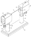
図1を参照するに、本発明の光学測定装置を、例えば工作機械上で用いるのに適した工具設定装置として作動するように構成した組立の一部分として示す。この装置は、光ビーム12を放出する光放出ユニット10と光ビーム12を検出する光検出ユニット14とを有する。光放出ユニット10および検出ユニット14への、電源ケーブルおよび信号制御ケーブルを、入口ポート16を介して取りまわす。ユニット10および14の双方を、柱18を介して機械の基台に取り付けるが、ここで、これらユニットの双方を取り付ける基台20を介して、あるいは、これらユニットを用いる機械の基台に直接取り付けるのが有効である。作動にあたっては、光ビーム12が伝播する方向を横切る方向に工具を動かすようにこの装置を取り付けた機械を作動させることにより、この装置を用いて工具の設定を行なう。光ビームが、予め定められたレベルの遮断を示すと、検出ユニット14はトリガ信号を発生し、このトリガ信号を、機械によって用いて、その相対的に移動可能な部分の相対位置を決定し、それにより、工具の寸法を決定することができる。このような装置の一例の機械的および光学的な、それ以上の詳細は、本特許出願人による欧州特許出願00303749.6号に記載されており(この出願を参照することにより本明細書の一部分とする)、従ってここではその詳細を再掲しない。
【0013】
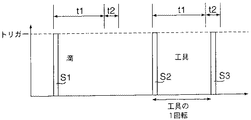
図2は、種々の状態における検出器からの出力を示す。光ビームが予め定めた範囲に遮断されると、電圧パルスで示されるように、検出器の出力が高レベルとなる(すなわち、検出信号を発生する)。図の左側における第1パルスS1からわかるように、クーラントの滴が光ビームを通過すると、このパルスが生じる。しかし、この第1の場合には、クーラントの滴は1回発生するのみであって、単一の短い持続時間のパルスが発生する。
【0014】
回転切断工具の刃が光路を遮断すると、上記と同様に、短い持続時間のパルスS2が発生するが、この場合には、同じ切断工具の刃が再び光路を遮断することに起因するパルスS3が発生する。なお、回転切刃がビーム中に到来するか、あるいは多数の刃をもつ工具の他の切刃がビームを順次に遮断するのにつれて、このパルスS2の後に他のパルスS3(1つしか図示していない)が続く。
【0015】
滴によるビームの遮断と、切断工具の刃が第1回目としてビームを遮断すること(これは切刃の位置を測定するために検出が必要となる事象である)との差異を区別できるようにするために、本発明の光学測定装置においては、検出器におけるタイマーによって、検出器がその検出信号を発生するのと同時に、第1の時間間隔t1を設定する。特定の実施例においては、時間間隔t1は、工具が1回転するのに要する時間に等しく設定される。時間間隔t1の終了時に、タイマーはt1よりも短い時間間隔t2を設定する。
【0016】
検出器は、時間間隔t2において第2の検出信号が得られるか否かをモニタする。第1の検出信号が滴であれば、この第2検出信号は生じることはない。これは、信号出力の高レベル状態、若しくは立上り端によって検出される。第2の検出信号が存在すると、検出器は、時間間隔t2の終了時に、「スキップ」信号若しくはトリガ信号を形成する。
【0017】
時間間隔t1およびt2は正確に知られているので、工具の切刃がビームを遮断することに起因する検出器出力の、第1の立上り端の生起瞬時を算出することができる。
【0018】
これらのタイミングを計算するためには、機械のスピンドル、従って切断工具の回転速度を設定する必要がある。測定動作に要する時間を妥当な水準に抑えるために、実験中は、スピンドルの回転速度を1000rpmとし、時間間隔t1を見かけ上60msとした。しかし、時間間隔t2は、スピンドルの回転速度の僅かな変化、例えば、最大5%(この場合には、時間間隔t1の変動は3msとなる)にも対応可能となるように充分大きく設定する必要がある。
【0019】
時間間隔t2におけるトリガ信号を、その中心に位置させるためには、t2を、t1+1/2・tにおいて設定し、これが60msに等しくなるようにする必要がある。従って、t1は実際には58.5msに設定される。
【0020】
工具の回転速度は、測定に先立って既知である必要はない。その理由は、検出器によって発生させられた連続するパルスの列から、最初の2つの連続するパルスの立上り端間の距離にタイミングを合わせることによって回転速度を測定することができるからである。時間間隔(t1)は、第2および第3の立上り端の間に設定することができ、およびt2は、第3の立上り端から計時される。
【0021】
本発明装置の基本的な構成要素をブロック図の形態で図3に示す。送出器10からの光ビーム12は検出器14に入射し、検出回路72中の光検出素子に入射し、ビームが遮断されたときに信号を発生する。検出回路72において発生した信号は、信号分析のための必要なタイミングデバイスを含む信号プロセッサ74に供給される。検出器の出力信号は、機械コントローラ80に直接に供給される。このコントローラは、機械を停止させ、そして機械のスケールの読み取りを評価して、機械の位置を決定する。
【0022】
図4は、他の実施例を示し、ここでは、検出器において1つまたは2つ以上のクロックを用い、各クロックによって、検出器により開始させられたパルス列を発生させ、ビームが遮断されたことを示す信号を発する。
【0023】
図4aは、ビームを遮断する歯および滴の混合により生成された事象の列の例を示す。
【0024】
図4bは、これらの事象により生成された信号を、検出器の信号プロセッサにおけるコンパレータの出力端においてパルスに変換したものを示す。
【0025】
図4cは、単一クロックを用いるときに検出器に生じる状態を示す。
【0026】
図4dは、第2のクロックを用いるときに検出器に生じる状態を示す。
【0027】
図4eおよびfは、コンパレータの出力を、第1および第2クロック出力と組み合わせた結果をそれぞれ示す。
【0028】
図4aからわかるように、滴は不規則な時間間隔で生起してビームを遮断するのに対して、工具の刃によるビームの遮断は規則的な時間間隔で起こる。各ビームの遮断を、番号付けられた事象Eと呼ぶ。
【0029】
図4bは、それらの事象に対応する、コンパレータの出力パルスを示す。
【0030】
図4cは、第1クロックは、事象E1が生起するときに開始するが、第2のクロックパルスが信号プロセッサに供給されるときに何らの事象も生じていないので、クロックは停止することを示している。同じく滴による事象E3の生起時に、第1クロックは、再度、開始するが、その第2パルスは、再び事象E4と事象E5との間に生起するので、そのクロックは事象E4を認識せず、停止する。事象E5において再び第1クロックが開始するときも上記と同様である。事象E7において、再度、第1クロックが開始するときにのみ、そのパルスは工具の切刃が事象E9においてビームを遮断するのと同期し、事象E7についてのトリガ信号が発生する。この信号は、事象E6において切刃が最初にビームを遮断したことを見逃しており、誤った読み取りを生じてしまう。
【0031】
しかし、図4dに示すように、2つのクロックを用いる実施例では、事象E6において第2クロックが開始する。その理由は、そのときに第1クロックが走っているからである。事象E6は切断工具の刃によるビーム遮断であるので、クロックパルスが発生しているときに、次の事象E7が生じる。信号プロセッサは、これらのクロックパルスと事象とが今や同期したことを認識し、そして、パルスの立上り端においてトリガ信号を発生させる。クロックパルスの発生とビーム遮断とは同期しているので、最初のビーム遮断が生じた時刻を容易に決定することができる。
【0032】
第1の事象が工具の切刃により生じる場合には、この状況はさほど複雑ではない。その理由は、第1クロックが開始し、その最初のパルスの間に同期した事象を認識し、その時刻にトリガ信号が発生するからである。
【0033】
第1事象と第2事象との間に滴が生じると、これは第1クロックによって無視される。その理由は、この滴が最初のパルスの間に生じないからである。従って、これらの状況下では、滴はトリガ信号の生成に影響を及ぼさない。
【0034】
これまでは、1または2のクロックを用いるものとして本発明を説明してきたが、異なる周波数のさらに多くのクロックを用いると、他の利点を達成することもできる。
【0035】
例えば、スピンドルの回転を種々の速度としたときにも、既存のクロックのタイミングを再設定する必要なく装置を用いることができ、しかも、追加のクロックによって、この装置が多数の滴が予想される雰囲気に対処できる。クロックの個数は、得られる利点と追加の信号処理に要する費用との兼ね合いにより決定される。
【0036】
本発明は、工具が回転しないで、その工具の長さや直径を工具の設定中に測定したり、あるいは、工具の破損の検知にも用いることができる。このような実施例においては、工具をビームに対して適当な角度となるように移動させ、工具の先端や側面によりビームを遮断するようにする。検出器により発生された信号を用いて、信号プロセッサにおけるクロックを開始させて、時間t経過後に検出器の出力を評価する。時間t経過後に検出器の出力が依然として高レベルであり、信号が依然として存在すると認識された場合には、信号プロセッサによりトリガ信号が発生される。
【0037】
また、別の実施態様においては、信号プロセッサに、同期事象を識別するデバイスを組み込んでもよい。かかるデバイスへの入力は、規則的間隔におけるサンプルであり、それらサンプルは固定長のバッファにストアされ、新たな内容によって、既にストアされている過去のサンプルをいつも置き換える。バッファは、検出器の出力を監視し、サンプリングがなされる度毎に検出器出力の現在の状態をストアするシフトレジスタを用いて実施することが可能である。このバッファが2バイトにわたって分割されているときには、半部を比較することにより、繰り返しパターンに対するテストを行うことができる。例えば、仮に繰返しパターンのサンプル速度が工具の回転速度の8倍であり、しかも各サンプルの結果が、2つの8ビットレジスタを介してシフトされるとすると、最初の信号が生じるときに、これはレジスタの第1セル中に高レベル(1)として現れる。そのサンプルはレジスタ中を移動して、第2半部の第1セルへと送られる。もし、同期する事象がない場合には、サンプルはレジスタを最後まで素通りすることになる。しかしながら、第1のサンプルが、レジスタの第2半部の第1セルに移動するときに、丁度別の高レベルのサンプルが、レジスタの第1半部の第1セルに受信されると、2つの半部は、再度一致することとなり、トリガ信号が発生する。
【0038】
本発明を、工作機械の光学的測定装置における擬似トリガ信号の除去の場合について説明してきたが、本発明の要旨は、他の形式の機械における他の形態の光学的測定装置を用いる広範な用途をもつものである。従って、本発明の範囲は、添付の請求の範囲によって規定されるべきものである。
【図面の簡単な説明】
本発明の例を、添付図面を参照して説明するが、これらの例はあくまでも例のみである。
【図1】 本発明を組み込んだ光学測定装置の斜視図である。
【図2】 図1の検出器の出力の表示である。
【図3】 装置の基本構成要素を示すブロック図である。
【図4】 4aから4fの直線に、検出器の信号処理回路の種々の部分で発生される信号を示している。
【符号の説明】
10 送出器
12 光路
14 検出器
72 検出回路
74 信号処理
80 機械コントローラ[0001]
The present invention relates to an optical measurement device that enables a coordinate positioning machine (such as a machine tool) to determine the position of an object relative to a reference point.
[0002]
A conventionally known tool setting device for a machine tool includes a light source that generates a thin light beam incident on a detector. During the tool setting operation, the machine is operated to move the tool in a direction perpendicular to the direction of propagation of the light beam until a portion of the tool interrupts the optical path of the light beam. This blockage detection is used to generate a trigger signal in the detection unit, which trigger signal is used by the machine to determine the relative position of the moving part in order to determine the dimensions of the tool. Such devices are disclosed in, for example, German patents DE 4238504 and DE 4244869, French patent 2343555, European patent 98930, and US Pat. No. 4,518,257. Furthermore, such a device may be used to measure the length and diameter of a tool in order to monitor tool breakage and wear.
[0003]
The devices disclosed in the above mentioned patent specifications use a thin light beam through which a tool enters or passes. As the tool enters the beam, the detection unit detects from the resulting decrease in the amount of light incident on it. When the tool enters the beam, a trigger signal can be generated as a result of the amount of light incident on the detector decreasing to a predetermined amount.
[0004]
The problem with such an optical measuring device is that during the measurement, the coolant used in the machine drops through the beam or enters the beam with a rotating tool and creates a false trigger signal. It means that.
[0005]
One solution that solves this problem and is currently used is that of the machine controller to make several measurements until a pre-selected number of measurements are obtained that fall within a given tolerance. To program the software. The tool position is then estimated as the average of these measurements. This method has the problem that if a significant number of repeated measurements are required, the measurement cycle time will require an unacceptably long time.
[0006]
The present invention seeks to alleviate this problem by providing a measurement method that allows discrimination between true tool detection signals and signals generated by coolant drops.
[0007]
According to an aspect of the present invention, there is provided a method for measuring an object on a machine using an optical measurement device including a light source that emits a light beam incident on a detector, and each time the beam is interrupted. When a detection signal is generated in the detector, the frequency and / or duration of the detection signal is evaluated, and there is a further detection signal in the detector during a specific time interval from the generation of the previous detection signal Only, there is provided a method comprising the step of transmitting an output signal from the detector.
[0008]
The timing of the detection signal can be achieved by various methods.
[0009]
In one embodiment of the invention, the tool is preferably rotated at a specific known speed. This results in a regular sequence of the signals in the detector when the cutting edge (s) of the tool interrupts the beam. Generation of the first of the signals is used to initiate a timing sequence in the detector that sets a time interval (t 1 ) substantially equal to the time required for the tool to make one revolution, ( This is followed by a time interval (t 2 ) that is substantially shorter than t 1 ). If it is the tool that generated the signal at the detector, when the cutting edge of the tool has been turned back during the time interval t 2, the second signal is generated. When this event occurs, the detector emits an output signal.
[0010]
Alternatively, the generation of the detection signal by the detector can be used to start a clock that generates short time interval pulses that are synchronized with the rotational speed of the tool. Again, if a second detection signal is generated in the detector during the generation of such a pulse, the detector emits an output signal. A number of clocks may be used that begin operation when the detector generates its detection signal, each of which is a second in the detector during the next of the pulse. If no detection signal is generated, the operation is stopped.
[0011]
The present invention also includes an optical measurement device for performing the above-described method, the device comprising a light source that generates a light beam, and a detector that receives the beam and generates a signal when the beam is interrupted. The detector comprises a detection circuit that generates a signal each time a beam is interrupted, and the frequency and / or duration of generation of the signal, and within a specific time interval after generation of the signal, the detector Signal processing means for generating an output signal only when the second signal is generated by the detection circuit.
[0012]
Referring to FIG. 1, the optical measurement device of the present invention is shown as part of an assembly configured to operate as a tool setting device suitable for use on, for example, a machine tool. The apparatus includes a
[0013]
FIG. 2 shows the output from the detector in various states. When the light beam is blocked to a predetermined range, the output of the detector goes high (ie, generates a detection signal) as indicated by the voltage pulse. As can be seen from the first pulse S1 on the left side of the figure, this pulse occurs when a droplet of coolant passes through the light beam. However, in this first case, the coolant drop only occurs once and a single short duration pulse is generated.
[0014]
When the blade of the rotary cutting tool interrupts the optical path, a short duration pulse S2 is generated as described above. In this case, the pulse S3 caused by the same cutting tool blade interrupting the optical path again is generated. appear. Note that this pulse S2 is followed by another pulse S3 (only one is shown) as the rotary cutting edge arrives in the beam or as the other cutting edge of the tool with multiple blades sequentially blocks the beam. Not followed).
[0015]
To be able to distinguish the difference between the beam blocking by the drop and the cutting tool blade blocking the beam for the first time (this is an event that needs to be detected to measure the position of the cutting blade) Therefore, in the optical measurement apparatus of the present invention, the first time interval t 1 is set by the timer in the detector at the same time when the detector generates the detection signal. In a particular embodiment, the time interval t 1 is set equal to the time it takes for the tool to make one revolution. At the end of time interval t 1 , the timer sets a time interval t 2 that is shorter than t 1 .
[0016]
Detector monitors whether the second detection signal is obtained in the time interval t 2. If the first detection signal is a drop, this second detection signal will not occur. This is detected by the high level state of the signal output or the rising edge. In the presence of the second detection signal, the detector forms a “skip” signal or trigger signal at the end of time interval t 2 .
[0017]
Since the time intervals t 1 and t 2 are known exactly, it is possible to calculate the moment of occurrence of the first rising edge of the detector output resulting from the cutting edge of the tool blocking the beam.
[0018]
In order to calculate these timings, it is necessary to set the rotational speed of the machine spindle and hence the cutting tool. In order to keep the time required for the measurement operation to a reasonable level, the rotation speed of the spindle was set to 1000 rpm and the time interval t 1 was apparently set to 60 ms during the experiment. However, the time interval t 2 is set to be sufficiently large so as to be able to cope with a slight change in the rotation speed of the spindle, for example, a maximum of 5% (in this case, the fluctuation of the time interval t 1 is 3 ms). There is a need to.
[0019]
In order to center the trigger signal at time interval t 2, it is necessary to set t 2 at t 1 + 1/2 · t, which is equal to 60 ms. Therefore, t 1 is actually set to 58.5 ms.
[0020]
The rotational speed of the tool need not be known prior to measurement. The reason is that the rotational speed can be measured from the sequence of consecutive pulses generated by the detector by timing the distance between the rising edges of the first two consecutive pulses. The time interval (t 1 ) can be set between the second and third rising edges, and t 2 is timed from the third rising edge.
[0021]
The basic components of the inventive device are shown in block diagram form in FIG. The
[0022]
FIG. 4 shows another embodiment in which one or more clocks are used in the detector, each generating a pulse train initiated by the detector and the beam being interrupted. A signal indicating that
[0023]
FIG. 4a shows an example sequence of events generated by a mixture of teeth and drops that block the beam.
[0024]
FIG. 4b shows the signal generated by these events converted to a pulse at the output of the comparator in the detector signal processor.
[0025]
FIG. 4c shows what happens to the detector when using a single clock.
[0026]
FIG. 4d shows what happens to the detector when using the second clock.
[0027]
Figures 4e and f show the results of combining the output of the comparator with the first and second clock outputs, respectively.
[0028]
As can be seen from FIG. 4a, drops occur at irregular time intervals and block the beam, whereas beam blocking by the tool blade occurs at regular time intervals. The blockage of each beam is referred to as numbered event E.
[0029]
FIG. 4b shows the output pulses of the comparator corresponding to those events.
[0030]
FIG. 4c shows that the first clock starts when event E1 occurs, but the clock stops because no event has occurred when the second clock pulse is supplied to the signal processor. ing. Also at the occurrence of event E3 due to a drop, the first clock starts again, but its second pulse occurs again between events E4 and E5, so that the clock does not recognize event E4, Stop. The same applies when the first clock starts again at event E5. At event E7 again, only when the first clock starts, the pulse is synchronized with the cutting edge of the tool interrupting the beam at event E9 and a trigger signal for event E7 is generated. This signal misses the event that the cutting edge first interrupted the beam at event E6, resulting in an erroneous reading.
[0031]
However, as shown in FIG. 4d, in an embodiment using two clocks, the second clock starts at event E6. The reason is that the first clock is running at that time. Since event E6 is a beam interruption by the cutting tool blade, the next event E7 occurs when a clock pulse is occurring. The signal processor recognizes that these clock pulses and events are now synchronized, and generates a trigger signal at the rising edge of the pulses. Since the generation of the clock pulse and the beam block are synchronized, the time when the first beam block occurs can be easily determined.
[0032]
If the first event is caused by the cutting edge of the tool, this situation is less complicated. This is because the first clock starts, recognizes a synchronized event during the first pulse, and a trigger signal is generated at that time.
[0033]
If a drop occurs between the first event and the second event, this is ignored by the first clock. The reason is that this drop does not occur during the first pulse. Thus, under these circumstances, the drop does not affect the generation of the trigger signal.
[0034]
So far, the present invention has been described as using one or two clocks, but other advantages can be achieved using more clocks of different frequencies.
[0035]
For example, the device can be used even when the spindle rotates at various speeds without having to reset the timing of the existing clock, and the additional clock can cause the device to expect a large number of drops. Can handle the atmosphere. The number of clocks is determined by a tradeoff between the benefits obtained and the cost of additional signal processing.
[0036]
The present invention can be used to measure the length and diameter of a tool during the setting of the tool without rotating the tool, or to detect the breakage of the tool. In such an embodiment, the tool is moved at an appropriate angle with respect to the beam, and the beam is blocked by the tip and side surfaces of the tool. The signal generated by the detector is used to start a clock in the signal processor and evaluate the detector output after time t. If the detector output is still high after time t and it is recognized that the signal is still present, a trigger signal is generated by the signal processor.
[0037]
In another embodiment, the signal processor may incorporate a device that identifies the synchronization event. The inputs to such devices are samples at regular intervals, which are stored in a fixed length buffer, and new content always replaces the previously stored past samples. The buffer can be implemented with a shift register that monitors the output of the detector and stores the current state of the detector output each time it is sampled. When this buffer is divided over 2 bytes, it is possible to test a repetitive pattern by comparing the halves. For example, if the sample rate of the repeating pattern is 8 times the rotational speed of the tool, and the result of each sample is shifted through two 8-bit registers, Appears as high level (1) in the first cell of the register. The sample moves through the register and is sent to the first cell in the second half. If there is no event to synchronize, the sample will pass through the register to the end. However, if another high level sample is received in the first cell of the first half of the register when the first sample moves to the first cell of the second half of the register, 2 The two halves will coincide again and a trigger signal is generated.
[0038]
Although the present invention has been described with respect to the removal of a false trigger signal in an optical measurement device of a machine tool, the gist of the present invention is a wide range of applications using other forms of optical measurement device in other types of machines. It has something. Accordingly, the scope of the invention should be defined by the appended claims.
[Brief description of the drawings]
Examples of the present invention will be described with reference to the accompanying drawings, which are only examples.
FIG. 1 is a perspective view of an optical measuring apparatus incorporating the present invention.
2 is a display of the output of the detector of FIG.
FIG. 3 is a block diagram showing basic components of the apparatus.
FIG. 4 shows the signals generated in various parts of the signal processing circuit of the detector in the straight lines 4a to 4f.
[Explanation of symbols]
DESCRIPTION OF
Claims (20)
前記光ビームが入射し、前記光ビームの所定の遮断が発生すると出力信号を発する検出器と、
信号プロセッサと
を備え、前記信号プロセッサは、規則的間隔における前記検出器からの信号の状態を示すサンプルをストアし、前記ストアされたサンプルにおいて繰り返しパターンをテストし、前記ストアされたサンプルが繰り返しパターンを示しているときはトリガ信号を発生することを特徴とする機械上の回転する対象物の計測を行なう装置。A light source that generates a light beam;
A detector that emits an output signal when the light beam is incident and a predetermined interruption of the light beam occurs;
A signal processor, wherein the signal processor stores samples indicative of the state of the signal from the detector at regular intervals , tests a repetitive pattern on the stored samples, and the stored samples are repetitive patterns A device for measuring a rotating object on a machine, characterized by generating a trigger signal when
ビームが遮断される毎に検出信号を検出器内に発生させるステップと、
規則的間隔における前記検出器からの信号の状態を示すサンプルをストアするステップと、
前記ストアされたサンプルにおいて繰り返しパターンをテストし、前記ストアされたサンプルが繰り返しパターンを示しているときはトリガ信号を発生するステップと
を備えたことを特徴とする方法。A method of measuring on a machine using a device having a light source that generates a light beam incident on a detector,
Generating a detection signal in the detector each time the beam is interrupted;
Storing a sample indicative of the state of the signal from the detector at regular intervals;
Testing a repetitive pattern on the stored sample and generating a trigger signal when the stored sample indicates a repetitive pattern.
前記対象物を回転させるステップと、
前記光源から前記光ビームを射出させるステップと、
前記光源からの光ビームが遮断されると前記検出器内で第1の検出信号を発生するステップと、
前記第1の検出信号が発生する場合の第1の時間間隔を提供するステップと、
前記第1の時間間隔より短く、前記第1の時間間隔の終了から開始される第2の時間間隔を提供するステップと、
前記第2の時間間隔おいて、前記検出器内で検出信号がさらにあるときに、前記検出器から出力信号を発するステップと
を備え、
前記第1の時間間隔は、前記対象物が回転するとき該対象物の端部が回転して再度戻るのに要する時間に実質的に等しいことを特徴とする方法。A method of measuring an object using an optical measurement device including a light source that generates a light beam and a detector that enters the light beam,
Rotating the object;
Emitting the light beam from the light source;
Generating a first detection signal in the detector when the light beam from the light source is interrupted;
Providing a first time interval when the first detection signal occurs;
Providing a second time interval shorter than the first time interval and starting from the end of the first time interval;
Emitting an output signal from the detector when there is further a detection signal in the detector at the second time interval, and
The method of claim 1, wherein the first time interval is substantially equal to the time required for the end of the object to rotate and return again when the object rotates.
前記クロックに、各々存続期間が前記第2の時間間隔と同じであり、前記工具の回転速度に同期するパルス列であって、第1のパルスは検出器に発生されている検出信号と同時に発されるパルス列の発生を開始させるステップと、
前記クロックパルスの存続中にも、前記検出器内で検出信号があるときのみ、前記検出器から出力信号を発するステップと、
前記検出器内で検出信号がないときには、前記クロックを停止するステップと
をさらに備えたことを特徴とする請求項8に記載の方法。The optical measurement device further includes a clock,
Each of the clocks has a duration that is the same as the second time interval, and is a pulse train that is synchronized with the rotational speed of the tool, the first pulse being generated simultaneously with the detection signal generated by the detector. Starting the generation of a pulse train
Emitting an output signal from the detector only when there is a detection signal in the detector during the duration of the clock pulse;
9. The method of claim 8, further comprising: stopping the clock when there is no detection signal in the detector.
第1のクロックに、検出器内に検出信号が発生すると、前記パルスの第1の列の発生を開始させるステップと、
第2のクロックに、第1のクロックの2つの連続するパルスの間隔中に、検出器内でのさらなる検出信号の発生とともに前記パルスの第2の列の発生を開始させるステップと、
第2の列における次のパルスの存在中に、検出器内に検出信号があり、検出器がパルスの第1の列に基づく出力信号を発していないときに、検出器から出力信号を発させるステップと
をさらに備えたことを特徴とする請求項9に記載の方法。The optical measuring device comprises two clocks;
Starting a first sequence of pulses when a detection signal is generated in the detector at a first clock; and
Causing the second clock to initiate the generation of the second train of pulses during the interval of two consecutive pulses of the first clock with the generation of further detection signals in the detector;
In the presence of the next pulse in the second train, there is a detection signal in the detector and the detector emits an output signal when the detector is not emitting an output signal based on the first train of pulses. The method of claim 9, further comprising:
検出器内に検出信号が発生され、かつ、前に開始されたクロックの全てが作動中であるときに、前記パルスのそれぞれの列の発生を連続して開始させるステップをさらに備えたことを特徴とする請求項11に記載の方法。The optical measuring device includes an additional clock;
Further comprising the step of sequentially starting the generation of each train of pulses when a detection signal is generated in the detector and all of the previously started clocks are in operation. The method according to claim 11.
工具の異なる回転速度に一致して設定された異なる周波数のパルスのそれぞれの列を生成するようにクロックを設定するステップと、
前記パルスの列の発生の開始を工具の回転速度に適合させるステップと
をさらに備えたことを特徴とする請求項11に記載の方法。The optical measuring device includes an additional clock;
Setting the clock to generate a respective sequence of pulses of different frequencies set to match different rotational speeds of the tool;
The method of claim 11, further comprising adapting a start of generation of the train of pulses to a rotational speed of the tool.
前記光ビームを受け取り、前記光ビームが遮断されると信号を送信する検出器と
を備え、前記検出器は、
前記光源からの光ビームが遮断されると前記検出器内で第1の検出信号を発生し、
前記第1の検出信号が発生する場合の第1の時間間隔を提供し、
前記第1の時間間隔より短く、前記第1の時間間隔の終了から開始される第2の時間間隔を提供し、
前記第2の時間間隔おいて、前記検出器内で検出信号がさらにあるときに、前記検出器から出力信号を発し、
前記第1の時間間隔は、前記対象物が回転するとき該対象物の端部が回転して再度戻るのに要する時間に実質的に等しいことを特徴とする対象物の計測を行なう装置。A light source that generates a light beam;
A detector for receiving the light beam and transmitting a signal when the light beam is interrupted, the detector comprising:
When the light beam from the light source is interrupted, a first detection signal is generated in the detector,
Providing a first time interval when the first detection signal occurs;
Providing a second time interval shorter than the first time interval and starting from the end of the first time interval;
Emitting an output signal from the detector when there is more detection signal in the detector at the second time interval;
The apparatus for measuring an object, wherein the first time interval is substantially equal to a time required for an end of the object to rotate and return again when the object rotates.
前記光ビームを受信し、および前記光ビームの所定の遮断が発生すると信号を送信するか、前記受信した光の範囲を示す信号を送信する検出器と、
前記検出器からの信号を処理し、出力を生成する信号プロセッサと
を備え、前記信号プロセッサは、前記信号の生成に続いて、前記対象物の少なくとも1回転に要する時間にほぼ同じだけの遅延の後、かつ前記信号が前記遅延の終了において存在する場合、前記検出器からの信号を処理し、出力を生成するか、または
前記検出器によって生成された信号が所定の範囲または程度に達するたびに、前記対象物の少なくとも1回転にほぼ同じ存続期間を有するクロックパルスを開始し、および前記クロックパルスの存続期間の最後でのみ出力を生成することを特徴とする回転する対象物の位置を判定する装置。A light source that generates a light beam;
A detector that receives the light beam and transmits a signal when a predetermined blockage of the light beam occurs or transmits a signal indicative of the range of the received light;
A signal processor that processes the signal from the detector and generates an output, the signal processor having a delay approximately equal to the time required for at least one revolution of the object following generation of the signal. Later, and if the signal is present at the end of the delay, each time it processes the signal from the detector and produces an output, or the signal generated by the detector reaches a predetermined range or degree Determining the position of the rotating object, starting a clock pulse having approximately the same duration for at least one revolution of the object and generating an output only at the end of the duration of the clock pulse apparatus.
前記対象物を回転させるステップと、
前記光源から光ビームを照射させるステップと、
前記光ビームと相対的に前記対象物を移動するステップと、
前記検出器において、光ビームの範囲を検出するステップと、
前記検出器において所定の範囲の光が存在するときは、前記検出器から信号を生成するステップと、
前記信号の生成に続いて、前記対象物の少なくとも1回転だけ前記出力を遅延するステップと、
前記所定の範囲の光が前記遅延の終了において存在するときのみ、前記光学測定装置からの信号を生成させるか、前記検出器によって生成された信号が生成されるたびに、前記対象物の少なくとも1回転にほぼ同じ存続期間を有するクロックパルスを開始し、および前記クロックパルスの最後まで前記出力を遅延するか、または2つのモニタされた出力が、前記対象物がそれぞれのモニタ中に、少なくとも1回転を満了するのに必要となるのとほぼ同じ間隔をもって発生するときのみ前記光学測定装置からの信号を生成させるステップと、
を備えたことを特徴とする方法。A method of determining the position of a rotating object and generating an output using an optical measurement device comprising a light source that generates a light beam and a detector that receives the light beam,
Rotating the object;
Irradiating a light beam from the light source;
Moving the object relative to the light beam;
Detecting a range of the light beam in the detector;
Generating a signal from the detector when a predetermined range of light is present at the detector;
Following the generation of the signal, delaying the output by at least one revolution of the object;
Only when the predetermined range of light is present at the end of the delay, at least one of the objects is generated each time the signal from the optical measurement device is generated or the signal generated by the detector is generated. Start a clock pulse that has approximately the same duration in rotation and delay the output until the end of the clock pulse, or two monitored outputs, at least one rotation of the object during each monitor Generating a signal from the optical measurement device only when it occurs at approximately the same interval as is required to expire
A method characterized by comprising:
Applications Claiming Priority (5)
| Application Number | Priority Date | Filing Date | Title |
|---|---|---|---|
| GB9927471.4 | 1999-11-22 | ||
| GBGB9927471.4A GB9927471D0 (en) | 1999-11-22 | 1999-11-22 | Position determining apparatus for coordinate positioning machine |
| GB0020929A GB0020929D0 (en) | 2000-08-25 | 2000-08-25 | Optical measuring apparatus for measuring tools on machine |
| GB0020929.6 | 2000-08-25 | ||
| PCT/GB2000/004403 WO2001038822A1 (en) | 1999-11-22 | 2000-11-17 | Optical measuring apparatus for measuring objects on machines |
Publications (3)
| Publication Number | Publication Date |
|---|---|
| JP2003524154A JP2003524154A (en) | 2003-08-12 |
| JP2003524154A5 JP2003524154A5 (en) | 2008-01-17 |
| JP4695808B2 true JP4695808B2 (en) | 2011-06-08 |
Family
ID=26244900
Family Applications (1)
| Application Number | Title | Priority Date | Filing Date |
|---|---|---|---|
| JP2001540323A Expired - Lifetime JP4695808B2 (en) | 1999-11-22 | 2000-11-17 | Optical measuring device for measuring objects on machines |
Country Status (8)
| Country | Link |
|---|---|
| US (3) | US6635894B1 (en) |
| EP (2) | EP1562020B1 (en) |
| JP (1) | JP4695808B2 (en) |
| KR (1) | KR100746932B1 (en) |
| CN (2) | CN1202403C (en) |
| AT (2) | ATE371164T1 (en) |
| DE (2) | DE60019399T2 (en) |
| WO (1) | WO2001038822A1 (en) |
Families Citing this family (24)
| Publication number | Priority date | Publication date | Assignee | Title |
|---|---|---|---|---|
| WO2003018251A1 (en) | 2001-08-20 | 2003-03-06 | Blum-Novotest Gmbh | Method and device for determining the position of rotation-driven tools |
| CA2476067C (en) | 2002-03-13 | 2011-09-20 | Janssen Pharmaceutica N.V. | Carbonylamino-derivatives as novel inhibitors of histone deacetylase |
| GB0210175D0 (en) * | 2002-05-03 | 2002-06-12 | Renishaw Plc | Broken tool detector |
| US20050230605A1 (en) * | 2004-04-20 | 2005-10-20 | Hamid Pishdadian | Method of measuring using a binary optical sensor |
| KR20070053319A (en) * | 2004-09-08 | 2007-05-23 | 레니쇼우 피엘씨 | Detection device and method |
| GB0625387D0 (en) * | 2006-12-21 | 2007-01-31 | Renishaw Plc | Object detector and method |
| GB0708499D0 (en) | 2007-05-02 | 2007-06-06 | Renishaw Plc | Tool setting or analysis device |
| DE202007007160U1 (en) * | 2007-05-19 | 2007-08-02 | Leica Microsystems Nussloch Gmbh | Device for producing thin sections |
| DE102007047499B4 (en) * | 2007-10-04 | 2017-04-13 | E. Zoller GmbH & Co. KG Einstell- und Messgeräte | Method and device for acquiring information of a tool |
| EP2402714B1 (en) | 2010-07-02 | 2013-04-17 | Tesa Sa | Dimension measuring device |
| CN103433810B (en) * | 2013-07-19 | 2014-08-27 | 华中科技大学 | Complicated curve surface normal vector on-machine detection device and method |
| CN104439560B (en) * | 2013-10-24 | 2017-07-18 | 高桥金属制品(苏州)有限公司 | A kind of tapping machine light current induction controller |
| DE102016012727A1 (en) * | 2016-10-24 | 2018-04-26 | Blum-Novotest Gmbh | Measuring system for measuring on tools in a machine tool |
| DE102016012726A1 (en) * | 2016-10-24 | 2018-04-26 | Blum-Novotest Gmbh | Measuring system for measuring on tools in a machine tool |
| EP3450936A1 (en) * | 2017-09-05 | 2019-03-06 | Renishaw PLC | Optical apparatus and method for assessing the beam profile of a non-contact tool setting apparatus |
| EP3450909A1 (en) * | 2017-09-05 | 2019-03-06 | Renishaw PLC | Non-contact optical tool setting apparatus and method |
| EP3450097A1 (en) * | 2017-09-05 | 2019-03-06 | Renishaw PLC | Non-contact optical tool setting apparatus and method |
| EP3456469A1 (en) * | 2017-09-13 | 2019-03-20 | Renishaw PLC | Non-contact tool setting apparatus and method |
| CN110796209A (en) * | 2018-08-03 | 2020-02-14 | 杭州海康机器人技术有限公司 | Trigger detection method, device and system |
| DE102018006653A1 (en) * | 2018-08-22 | 2020-02-27 | Blum-Novotest Gmbh | Tool control in a workpiece processing machine |
| EP3637043A1 (en) | 2018-10-09 | 2020-04-15 | Renishaw PLC | Non-contact tool measurement apparatus |
| GB202016009D0 (en) * | 2020-10-09 | 2020-11-25 | Renishaw Plc | Method for measuring non-toothed tools using a non-contact tool setter |
| TWI749961B (en) * | 2020-12-22 | 2021-12-11 | 雷應科技股份有限公司 | Tool detector |
| CN113433129B (en) * | 2021-07-05 | 2023-01-06 | 无锡贝斯特精机股份有限公司 | Six-axis robot deburring cutter detection mechanism and method thereof |
Citations (6)
| Publication number | Priority date | Publication date | Assignee | Title |
|---|---|---|---|---|
| JPH0278904A (en) * | 1988-09-14 | 1990-03-19 | Toupure Kk | Measuring method for rotary tool |
| JPH0691427A (en) * | 1992-09-09 | 1994-04-05 | Nkk Corp | Missing tooth detection device for intermittent tooth-shaped body |
| JPH08197382A (en) * | 1995-01-30 | 1996-08-06 | Toshiba Mach Co Ltd | Chip attachment detection method for tool and its device |
| JPH10138099A (en) * | 1996-11-05 | 1998-05-26 | Toyoda Mach Works Ltd | Tool tip position detection device, and numerical control machine tool provided therewith |
| JPH11188577A (en) * | 1997-12-26 | 1999-07-13 | Okuma Corp | Run-out detecting method of cutter tool |
| JP2003512185A (en) * | 1999-10-19 | 2003-04-02 | ブルム‐ノヴォテスト・ゲゼルシャフト・ミット・ベシュレンクテル・ハフツング | Method and apparatus for testing the geometry of a cutting edge of a rotatably driven tool |
Family Cites Families (19)
| Publication number | Priority date | Publication date | Assignee | Title |
|---|---|---|---|---|
| FR2123753A5 (en) | 1971-01-29 | 1972-09-15 | Cometa Sa | |
| FR2343555A1 (en) | 1976-03-12 | 1977-10-07 | Dassault Avions | Milling machine cutting tool height setter - with tool lowered to interrupt laser beam and height accurately indicated by electronic voltmeter |
| US4373804A (en) * | 1979-04-30 | 1983-02-15 | Diffracto Ltd. | Method and apparatus for electro-optically determining the dimension, location and attitude of objects |
| US4502823A (en) | 1981-12-21 | 1985-03-05 | Sperry Corporation | Broken drill bit detector |
| DE3218754C2 (en) | 1982-05-18 | 1985-11-28 | Friedrich Deckel AG, 8000 München | Method and device for measuring a tool clamped in an adjustable tool holder of a machine tool |
| US4518257A (en) | 1982-07-28 | 1985-05-21 | General Electric Company | Optical inspection system and method |
| CH677892A5 (en) * | 1988-12-21 | 1991-07-15 | Rollomatic Sa | |
| DE3905949A1 (en) | 1989-02-25 | 1990-08-30 | Herbert Prof Dr Ing Schulz | METHOD FOR MEASURING CUTTING EDGES |
| DE69117715T2 (en) * | 1990-12-31 | 1996-07-18 | Excellon Automation | Monitoring the condition of a rotating tool |
| DE69223544T2 (en) | 1991-04-26 | 1998-07-09 | Nippon Telegraph & Telephone | Method and device for measuring the profile of an object |
| DE69205786T2 (en) * | 1991-08-21 | 1996-03-28 | Tokyo Seimitsu Co Ltd | Sheet position detection device. |
| DE59309003D1 (en) | 1992-08-25 | 1998-10-29 | Leuze Electronic Gmbh & Co | Device consisting of a transmitter and a receiver for detecting objects |
| DE4244869C2 (en) | 1992-11-14 | 1997-08-28 | Chiron Werke Gmbh | Tool measuring method for machine spindle |
| DE4323910C2 (en) | 1993-07-16 | 1995-08-10 | Leuze Electronic Gmbh & Co | Photoelectric sensor with evaluation electronics for the detection of interference signals |
| US5940787A (en) * | 1993-12-10 | 1999-08-17 | U.S. Tech Corporation | Apparatuses and methods of monitoring the condition of tools and workpieces |
| US5841662A (en) * | 1996-07-31 | 1998-11-24 | Coburn Optical Industries, Inc. | Method and apparatus for chucked work piece recognition |
| US6111262A (en) * | 1998-10-30 | 2000-08-29 | Sumitomo Metal Industries, Ltd. | Method for measuring a diameter of a crystal |
| US6496273B1 (en) | 1999-05-05 | 2002-12-17 | Renishaw Plc | Position determining apparatus for coordinate positioning machine |
| KR100906472B1 (en) * | 2002-05-21 | 2009-07-08 | 삼성전자주식회사 | Apparatus for reproducing the optical recordable medium using multiple dectector |
-
1999
- 1999-11-17 US US09/889,305 patent/US6635894B1/en not_active Expired - Lifetime
-
2000
- 2000-11-17 EP EP05075841A patent/EP1562020B1/en not_active Expired - Lifetime
- 2000-11-17 AT AT05075841T patent/ATE371164T1/en not_active IP Right Cessation
- 2000-11-17 DE DE60019399T patent/DE60019399T2/en not_active Expired - Lifetime
- 2000-11-17 AT AT00976187T patent/ATE293243T1/en not_active IP Right Cessation
- 2000-11-17 WO PCT/GB2000/004403 patent/WO2001038822A1/en active IP Right Grant
- 2000-11-17 DE DE60036144T patent/DE60036144T2/en not_active Expired - Lifetime
- 2000-11-17 JP JP2001540323A patent/JP4695808B2/en not_active Expired - Lifetime
- 2000-11-17 CN CNB008030014A patent/CN1202403C/en not_active Expired - Fee Related
- 2000-11-17 KR KR1020017009080A patent/KR100746932B1/en not_active IP Right Cessation
- 2000-11-17 EP EP00976187A patent/EP1144944B1/en not_active Expired - Lifetime
- 2000-11-17 CN CN200510064136XA patent/CN1660541B/en not_active Expired - Fee Related
-
2003
- 2003-10-06 US US10/678,075 patent/US6878953B2/en not_active Expired - Lifetime
-
2004
- 2004-09-23 US US10/947,345 patent/US7053392B2/en not_active Expired - Lifetime
Patent Citations (6)
| Publication number | Priority date | Publication date | Assignee | Title |
|---|---|---|---|---|
| JPH0278904A (en) * | 1988-09-14 | 1990-03-19 | Toupure Kk | Measuring method for rotary tool |
| JPH0691427A (en) * | 1992-09-09 | 1994-04-05 | Nkk Corp | Missing tooth detection device for intermittent tooth-shaped body |
| JPH08197382A (en) * | 1995-01-30 | 1996-08-06 | Toshiba Mach Co Ltd | Chip attachment detection method for tool and its device |
| JPH10138099A (en) * | 1996-11-05 | 1998-05-26 | Toyoda Mach Works Ltd | Tool tip position detection device, and numerical control machine tool provided therewith |
| JPH11188577A (en) * | 1997-12-26 | 1999-07-13 | Okuma Corp | Run-out detecting method of cutter tool |
| JP2003512185A (en) * | 1999-10-19 | 2003-04-02 | ブルム‐ノヴォテスト・ゲゼルシャフト・ミット・ベシュレンクテル・ハフツング | Method and apparatus for testing the geometry of a cutting edge of a rotatably driven tool |
Also Published As
| Publication number | Publication date |
|---|---|
| US6878953B2 (en) | 2005-04-12 |
| ATE371164T1 (en) | 2007-09-15 |
| US7053392B2 (en) | 2006-05-30 |
| US20040069936A1 (en) | 2004-04-15 |
| WO2001038822A1 (en) | 2001-05-31 |
| EP1144944B1 (en) | 2005-04-13 |
| KR20010101597A (en) | 2001-11-14 |
| DE60019399D1 (en) | 2005-05-19 |
| JP2003524154A (en) | 2003-08-12 |
| EP1562020A1 (en) | 2005-08-10 |
| CN1660541A (en) | 2005-08-31 |
| DE60036144D1 (en) | 2007-10-04 |
| CN1338040A (en) | 2002-02-27 |
| DE60019399T2 (en) | 2005-09-22 |
| EP1144944A1 (en) | 2001-10-17 |
| DE60036144T2 (en) | 2008-01-03 |
| KR100746932B1 (en) | 2007-08-08 |
| US20050167619A1 (en) | 2005-08-04 |
| CN1660541B (en) | 2010-12-01 |
| ATE293243T1 (en) | 2005-04-15 |
| US6635894B1 (en) | 2003-10-21 |
| EP1562020B1 (en) | 2007-08-22 |
| CN1202403C (en) | 2005-05-18 |
Similar Documents
| Publication | Publication Date | Title |
|---|---|---|
| JP4695808B2 (en) | Optical measuring device for measuring objects on machines | |
| US6597464B2 (en) | Method and device for testing a cutting-edge geometry of a rotatably drivable tool | |
| CN110879298B (en) | Speed acquisition method based on communication type encoder | |
| US6597205B2 (en) | High accuracy method for determining the frequency of a pulse input signal over a wide frequency range | |
| JPH0718692B2 (en) | Three-dimensional object shape detection device by optical cutting method | |
| CN101726625A (en) | Device for preventing rotating speed measured value from jumping off and method thereof | |
| JP2007163500A (en) | System and method for establishing decoder processing velocity, adjusting orthogonal encoder | |
| TW534976B (en) | Optical measuring apparatus for measuring objects on machines | |
| JP2008089409A (en) | Rotational speed detector | |
| JP2001133364A (en) | Contact detecting and monitoring device | |
| JP3599295B2 (en) | Optical dimension measuring device | |
| KR100206779B1 (en) | Method and system for calculating the remnant of tape | |
| JPH01304360A (en) | Method for detecting speed of motor | |
| JP2006329815A (en) | Tachometer | |
| SU1714340A1 (en) | Shaft angular position tester | |
| KR100494899B1 (en) | Apparatus for measuring rotation for valve in engines | |
| JPH0839298A (en) | Slide stop time measuring instrument of press machine | |
| SU951096A1 (en) | Device for revealing mechanism flaws | |
| JP3702103B2 (en) | Optical dimension measuring device | |
| JP4162426B2 (en) | Pass / fail judgment output method and apparatus for measuring machine | |
| SU1177741A1 (en) | Synchronizing device for ultrasonic flaw detector | |
| JP2005257482A (en) | Measurement controller | |
| KR0164046B1 (en) | Rotary speed tracking apparatus and method of motor by speed adaptive t method | |
| JP2595342B2 (en) | Laser measuring device | |
| JPH10304700A (en) | Power swing detection device of stepper motor |
Legal Events
| Date | Code | Title | Description |
|---|---|---|---|
| A521 | Request for written amendment filed |
Free format text: JAPANESE INTERMEDIATE CODE: A523 Effective date: 20071119 |
|
| A621 | Written request for application examination |
Free format text: JAPANESE INTERMEDIATE CODE: A621 Effective date: 20071119 |
|
| RD04 | Notification of resignation of power of attorney |
Free format text: JAPANESE INTERMEDIATE CODE: A7424 Effective date: 20071119 |
|
| A131 | Notification of reasons for refusal |
Free format text: JAPANESE INTERMEDIATE CODE: A131 Effective date: 20100216 |
|
| A601 | Written request for extension of time |
Free format text: JAPANESE INTERMEDIATE CODE: A601 Effective date: 20100514 |
|
| A602 | Written permission of extension of time |
Free format text: JAPANESE INTERMEDIATE CODE: A602 Effective date: 20100521 |
|
| A521 | Request for written amendment filed |
Free format text: JAPANESE INTERMEDIATE CODE: A523 Effective date: 20100616 |
|
| A02 | Decision of refusal |
Free format text: JAPANESE INTERMEDIATE CODE: A02 Effective date: 20100817 |
|
| A521 | Request for written amendment filed |
Free format text: JAPANESE INTERMEDIATE CODE: A523 Effective date: 20101217 |
|
| RD13 | Notification of appointment of power of sub attorney |
Free format text: JAPANESE INTERMEDIATE CODE: A7433 Effective date: 20101220 |
|
| A521 | Request for written amendment filed |
Free format text: JAPANESE INTERMEDIATE CODE: A821 Effective date: 20101220 |
|
| A911 | Transfer to examiner for re-examination before appeal (zenchi) |
Free format text: JAPANESE INTERMEDIATE CODE: A911 Effective date: 20110117 |
|
| TRDD | Decision of grant or rejection written | ||
| A01 | Written decision to grant a patent or to grant a registration (utility model) |
Free format text: JAPANESE INTERMEDIATE CODE: A01 Effective date: 20110218 |
|
| A01 | Written decision to grant a patent or to grant a registration (utility model) |
Free format text: JAPANESE INTERMEDIATE CODE: A01 |
|
| A61 | First payment of annual fees (during grant procedure) |
Free format text: JAPANESE INTERMEDIATE CODE: A61 Effective date: 20110228 |
|
| FPAY | Renewal fee payment (event date is renewal date of database) |
Free format text: PAYMENT UNTIL: 20140304 Year of fee payment: 3 |
|
| R150 | Certificate of patent or registration of utility model |
Ref document number: 4695808 Country of ref document: JP Free format text: JAPANESE INTERMEDIATE CODE: R150 Free format text: JAPANESE INTERMEDIATE CODE: R150 |
|
| R250 | Receipt of annual fees |
Free format text: JAPANESE INTERMEDIATE CODE: R250 |
|
| R250 | Receipt of annual fees |
Free format text: JAPANESE INTERMEDIATE CODE: R250 |
|
| R250 | Receipt of annual fees |
Free format text: JAPANESE INTERMEDIATE CODE: R250 |
|
| R250 | Receipt of annual fees |
Free format text: JAPANESE INTERMEDIATE CODE: R250 |
|
| R250 | Receipt of annual fees |
Free format text: JAPANESE INTERMEDIATE CODE: R250 |
|
| R250 | Receipt of annual fees |
Free format text: JAPANESE INTERMEDIATE CODE: R250 |
|
| R250 | Receipt of annual fees |
Free format text: JAPANESE INTERMEDIATE CODE: R250 |
|
| EXPY | Cancellation because of completion of term |