JP4695453B2 - Directional control valve - Google Patents
Directional control valve Download PDFInfo
- Publication number
- JP4695453B2 JP4695453B2 JP2005222162A JP2005222162A JP4695453B2 JP 4695453 B2 JP4695453 B2 JP 4695453B2 JP 2005222162 A JP2005222162 A JP 2005222162A JP 2005222162 A JP2005222162 A JP 2005222162A JP 4695453 B2 JP4695453 B2 JP 4695453B2
- Authority
- JP
- Japan
- Prior art keywords
- communication
- port
- movable member
- central axis
- axis direction
- Prior art date
- Legal status (The legal status is an assumption and is not a legal conclusion. Google has not performed a legal analysis and makes no representation as to the accuracy of the status listed.)
- Expired - Fee Related
Links
Images

Classifications
-
- F—MECHANICAL ENGINEERING; LIGHTING; HEATING; WEAPONS; BLASTING
- F16—ENGINEERING ELEMENTS AND UNITS; GENERAL MEASURES FOR PRODUCING AND MAINTAINING EFFECTIVE FUNCTIONING OF MACHINES OR INSTALLATIONS; THERMAL INSULATION IN GENERAL
- F16K—VALVES; TAPS; COCKS; ACTUATING-FLOATS; DEVICES FOR VENTING OR AERATING
- F16K11/00—Multiple-way valves, e.g. mixing valves; Pipe fittings incorporating such valves
- F16K11/02—Multiple-way valves, e.g. mixing valves; Pipe fittings incorporating such valves with all movable sealing faces moving as one unit
- F16K11/04—Multiple-way valves, e.g. mixing valves; Pipe fittings incorporating such valves with all movable sealing faces moving as one unit comprising only lift valves
- F16K11/048—Multiple-way valves, e.g. mixing valves; Pipe fittings incorporating such valves with all movable sealing faces moving as one unit comprising only lift valves with valve seats positioned between movable valve members
-
- Y—GENERAL TAGGING OF NEW TECHNOLOGICAL DEVELOPMENTS; GENERAL TAGGING OF CROSS-SECTIONAL TECHNOLOGIES SPANNING OVER SEVERAL SECTIONS OF THE IPC; TECHNICAL SUBJECTS COVERED BY FORMER USPC CROSS-REFERENCE ART COLLECTIONS [XRACs] AND DIGESTS
- Y10—TECHNICAL SUBJECTS COVERED BY FORMER USPC
- Y10T—TECHNICAL SUBJECTS COVERED BY FORMER US CLASSIFICATION
- Y10T137/00—Fluid handling
- Y10T137/8593—Systems
- Y10T137/86493—Multi-way valve unit
- Y10T137/86574—Supply and exhaust
- Y10T137/8667—Reciprocating valve
- Y10T137/86686—Plural disk or plug
-
- Y—GENERAL TAGGING OF NEW TECHNOLOGICAL DEVELOPMENTS; GENERAL TAGGING OF CROSS-SECTIONAL TECHNOLOGIES SPANNING OVER SEVERAL SECTIONS OF THE IPC; TECHNICAL SUBJECTS COVERED BY FORMER USPC CROSS-REFERENCE ART COLLECTIONS [XRACs] AND DIGESTS
- Y10—TECHNICAL SUBJECTS COVERED BY FORMER USPC
- Y10T—TECHNICAL SUBJECTS COVERED BY FORMER US CLASSIFICATION
- Y10T137/00—Fluid handling
- Y10T137/8593—Systems
- Y10T137/86919—Sequentially closing and opening alternately seating flow controllers
-
- Y—GENERAL TAGGING OF NEW TECHNOLOGICAL DEVELOPMENTS; GENERAL TAGGING OF CROSS-SECTIONAL TECHNOLOGIES SPANNING OVER SEVERAL SECTIONS OF THE IPC; TECHNICAL SUBJECTS COVERED BY FORMER USPC CROSS-REFERENCE ART COLLECTIONS [XRACs] AND DIGESTS
- Y10—TECHNICAL SUBJECTS COVERED BY FORMER USPC
- Y10T—TECHNICAL SUBJECTS COVERED BY FORMER US CLASSIFICATION
- Y10T137/00—Fluid handling
- Y10T137/8593—Systems
- Y10T137/87169—Supply and exhaust
- Y10T137/87217—Motor
- Y10T137/87225—Fluid motor
Landscapes
- Engineering & Computer Science (AREA)
- General Engineering & Computer Science (AREA)
- Mechanical Engineering (AREA)
- Multiple-Way Valves (AREA)
- Fuel-Injection Apparatus (AREA)
- Sliding Valves (AREA)
Description
本発明は、方向制御弁に関し、特に、第1及び第2連通切替ポートと連通対象ポートが形成された弁ボディと、弁ボディの内部で中心軸方向に移動して連通対象ポートに連通するポートを第1連通切替ポートと第2連通切替ポートの間で切り替える可動部材と、を備える方向制御弁に関する。 The present invention relates to a directional control valve, and in particular, a valve body in which first and second communication switching ports and a communication target port are formed, and a port that moves in a central axis direction inside the valve body and communicates with the communication target port. And a movable member that switches between the first communication switching port and the second communication switching port.
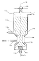
この種の方向制御弁の構成例を図13を用いて説明する。図13に示す方向制御弁は、連通切替ポート110a,110bと連通対象ポート110cとが形成された弁ボディ110と、弁ボディ110の内部でその中心軸116に平行な方向(以下、中心軸方向とする)に移動することで、連通対象ポート110cに連通するポートを連通切替ポート110aと連通切替ポート110bの間で切り替える可動部材112と、を備える三方弁である。連通切替ポート110aには作動油の圧力PLが供給され、連通切替ポート110bには作動油の圧力Pcが供給される。そして、連通対象ポート110cは、切替室(図示せず)に接続されている。ここで、連通切替ポート110bへの供給圧力Pcは、連通切替ポート110aへの供給圧力PLより高く設定されている。弁ボディ110の内部における可動部材112よりも中心軸方向の一方側(図13の上側)には制御室118が形成されており、制御室118内に供給される作動油の圧力によって可動部材112に中心軸方向の他方側(図13の下側)への推力を作用させることができる。制御室118内の圧力は、パイロット弁120の開閉動作により制御される。また、可動部材112には、ばね126により中心軸方向の一方側への付勢力が作用している。
A configuration example of this type of directional control valve will be described with reference to FIG. The directional control valve shown in FIG. 13 includes a
パイロット弁120が閉じている場合は、可動部材112は、制御室118内の圧力によって中心軸方向の他方側へ押圧されており、弁ボディ110に形成されたシート部110dに密着している。そのため、連通切替ポート110bと連通対象ポート110cが連通し且つ連通切替ポート110aと連通対象ポート110cの連通が遮断され、切替室内の圧力はPcとなる。次に、パイロット弁120を開けると、制御室118内の圧力が低下するため、可動部材112は、ばね126の付勢力によりシート部110dから離れて中心軸方向の一方側へ移動する。これによって、連通切替ポート110aと連通対象ポート110cが連通する。そして、可動部材112が弁ボディ110に形成されたシート部110eに密着することで、連通切替ポート110bと連通対象ポート110cの連通が遮断される。このように、パイロット弁120を閉状態から開状態に切り替えることで、連通対象ポート110cに連通するポートが連通切替ポート110bから連通切替ポート110aへ切り替えられる。その結果、切替室内の圧力がPcからPLへ低下する。
When the
次に、パイロット弁120を閉じると、制御室118内の圧力が増大するため、可動部材112は、制御室118内の圧力によりシート部110eから離れて中心軸方向の他方側へ移動する。これによって、連通切替ポート110bと連通対象ポート110cが連通する。そして、可動部材112が弁ボディ110に形成されたシート部110dに密着することで、連通切替ポート110aと連通対象ポート110cの連通が遮断される。このように、パイロット弁120を開状態から閉状態に切り替えることで、連通対象ポート110cに連通するポートが連通切替ポート110aから連通切替ポート110bへ切り替えられる。その結果、切替室内の圧力がPLからPcへ増大する。なお、この種の方向制御弁は、下記特許文献1にも開示されている。
Next, when the
また、その他の背景技術として、下記特許文献2〜5による燃料噴射装置が開示されている。 Moreover, the fuel injection apparatus by the following patent documents 2-5 is disclosed as other background art.
図13に示す方向制御弁においては、連通対象ポート110cに連通するポートを切り替える際に、連通切替ポート110a,110bの両方が連通対象ポート110cに連通する期間が存在する。例えば連通対象ポート110cに連通するポートを連通切替ポート110aから連通切替ポート110bへ切り替えるよう可動部材112が中心軸方向の他方側へ移動する行程では、可動部材112は、シート部110eに対し離れた後にシート部110dに密着する。そのため、図14に示すように、可動部材112がシート部110eに対し離れてからシート部110dに密着するまでの期間は、連通切替ポート110a,110bの両方が連通対象ポート110cに連通することになる。これによって、高圧側の連通切替ポート110bへ供給された作動油が低圧側の連通切替ポート110aへ流出し、作動油のエネルギー損失が増大してしまう。同様に、連通対象ポート110cに連通するポートを連通切替ポート110bから連通切替ポート110aへ切り替えるよう可動部材112が中心軸方向の一方側へ移動する行程でも、可動部材112がシート部110dに対し離れてからシート部110eに密着するまでの期間は、連通切替ポート110a,110bの両方が連通対象ポート110cに連通することになる。以上のように、図13に示す方向制御弁においては、連通対象ポート110cに連通するポートを切り替える際に、高圧側の連通切替ポート110bへ供給された作動油が低圧側の連通切替ポート110aへ流出し、作動油のエネルギー損失が増大してしまうという問題点がある。
In the directional control valve shown in FIG. 13, there is a period during which both the
本発明は、連通するポートを切り替える際に生じる作動流体のエネルギー損失を低減することができる方向制御弁を提供することを目的とする。 An object of this invention is to provide the direction control valve which can reduce the energy loss of the working fluid which arises when switching the port which communicates.
本発明に係る方向制御弁は、上述した目的を達成するために以下の手段を採った。 The direction control valve according to the present invention employs the following means in order to achieve the above-described object.
本発明に係る方向制御弁は、第1及び第2連通切替ポートと連通対象ポートが形成された弁ボディと、弁ボディの内部で中心軸方向に移動して連通対象ポートに連通するポートを第1連通切替ポートと第2連通切替ポートの間で切り替える可動部材と、を備える方向制御弁であって、可動部材は、中心軸方向の一方側へ移動して第1連通切替ポートと連通対象ポートを連通させ、中心軸方向の他方側へ移動して第1連通切替ポートと連通対象ポートの連通を遮断する第1可動部材と、中心軸方向の他方側へ移動して第2連通切替ポートと連通対象ポートを連通させ、中心軸方向の一方側へ移動して第2連通切替ポートと連通対象ポートの連通を遮断する第2可動部材と、を含み、弁ボディには、第1連通切替ポートと連通対象ポートの連通を遮断するために第1可動部材が中心軸方向の一方側から当接する第1シート部と、第2連通切替ポートと連通対象ポートの連通を遮断するために第2可動部材が中心軸方向の他方側から当接する第2シート部と、が設けられており、第1可動部材には、第2可動部材に対し中心軸方向の一方側から当接して中心軸方向の他方側への押圧力を作用させることが可能な押圧部と、第1シート部に対し中心軸方向の一方側から当接可能な第1当接部と、が設けられており、押圧部は、第1連通切替ポートと連通対象ポートが連通し且つ第2連通切替ポートと連通対象ポートの連通が遮断された状態では、第2可動部材に対し中心軸方向の一方側へ第1所定量離れており、第1可動部材に作用する中心軸方向の他方側への推力により第1連通切替ポートと連通対象ポートの連通を遮断し且つ第2連通切替ポートと連通対象ポートを連通させるよう第1及び第2可動部材が中心軸方向の他方側へ移動する行程では、第1可動部材は、中心軸方向の他方側へ第1所定量移動してから、押圧部にて第2可動部材を中心軸方向の他方側へ押圧し、第1可動部材または第2可動部材には、第1シート部と第1当接部の距離が第2所定量以下のときに第1連通切替ポートと連通対象ポートとの間の通路を塞ぐ遮断部が設けられており、第2連通切替ポートと連通対象ポートの連通を遮断し且つ第1連通切替ポートと連通対象ポートを連通させるよう第1及び第2可動部材が中心軸方向の一方側へ移動する行程では、遮断部は、第1当接部が第1シート部に対し中心軸方向の一方側へ第2所定量を超えて離れてから、第1連通切替ポートと連通対象ポートを連通させることを要旨とする。 The direction control valve according to the present invention includes a valve body in which the first and second communication switching ports and the communication target port are formed, and a port that moves in the central axis direction inside the valve body and communicates with the communication target port. A directional control valve comprising a movable member that switches between a first communication switching port and a second communication switching port, wherein the movable member moves to one side in the central axis direction to move to the first communication switching port and the communication target port A first movable member that moves to the other side in the central axis direction to block communication between the first communication switching port and the communication target port, and moves to the other side in the central axis direction to move to the second communication switching port. A second movable member that communicates the communication target port and moves to one side in the central axis direction to block communication between the second communication switching port and the communication target port, and the valve body includes a first communication switching port. To communicate with the target port The first movable member abuts from one side in the central axis direction to disconnect, and the second movable member is the other in the central axis direction to block communication between the second communication switching port and the communication target port. A second sheet portion that abuts from the side, and the first movable member abuts against the second movable member from one side in the central axis direction and applies a pressing force to the other side in the central axis direction. A pressing portion that can be actuated and a first abutting portion that can abut against the first sheet portion from one side in the central axis direction are provided, and the pressing portion is connected to the first communication switching port. In a state where the communication target port communicates and the communication between the second communication switching port and the communication target port is blocked, the first movable member is separated from the second movable member by a first predetermined amount toward one side in the central axis direction. The first communication switching port is driven by the thrust toward the other side of the central axis acting on In the stroke in which the first and second movable members move to the other side in the central axis direction so as to cut off the communication between the communication target port and the second communication switching port and the communication target port, the first movable member After the first predetermined amount is moved to the other side in the axial direction, the second movable member is pressed to the other side in the central axial direction by the pressing portion, and the first sheet member is provided on the first movable member or the second movable member. When the distance between the first contact portion and the first contact portion is equal to or less than the second predetermined amount, a blocking portion is provided to block the passage between the first communication switching port and the communication target port, and the second communication switching port and the communication target port are provided. In the stroke in which the first and second movable members move to one side in the central axis direction so as to block communication between the first communication switching port and the communication target port, the first contact portion is the first contact portion. A distance exceeding the second predetermined amount toward one side in the central axis direction with respect to one sheet portion Then, the gist is to make the first communication switching port communicate with the communication target port .
また、本発明の一態様では、弁ボディには、第1シート部と第1当接部の距離が第2所定量以下のときに遮断部が嵌め合わされる嵌合部が設けられており、遮断部が嵌合部に嵌め合わされることで第1連通切替ポートと連通対象ポートとの間の通路が塞がれることが好適である。 In one aspect of the present invention, the valve body is provided with a fitting portion into which the blocking portion is fitted when the distance between the first seat portion and the first contact portion is equal to or less than the second predetermined amount, It is preferable that the passage between the first communication switching port and the communication target port is closed by fitting the blocking portion to the fitting portion.
また、本発明の一態様では、第1可動部材または第2可動部材には、第1シート部と第1当接部の距離が第2所定量より長いときに嵌合部に対し接触しながら第1連通切替ポートと連通対象ポートを連通させる摺動案内部が設けられていることが好適である。 In one aspect of the present invention, the first movable member or the second movable member is in contact with the fitting portion when the distance between the first sheet portion and the first contact portion is longer than the second predetermined amount. It is preferable that a sliding guide portion that communicates between the first communication switching port and the communication target port is provided.
また、本発明の一態様では、第1シート部は、中心軸方向において第1連通切替ポートと連通対象ポートとの間に設けられており、遮断部は、第1連通切替ポートと連通対象ポートとの間の通路を、中心軸方向において第1シート部と連通対象ポートとの間で塞ぐことが好適である。 In one aspect of the present invention, the first seat portion is provided between the first communication switching port and the communication target port in the central axis direction, and the blocking portion is the first communication switching port and the communication target port. It is preferable to close the passage between the first seat portion and the communication target port in the central axis direction.
また、本発明の一態様では、第1シート部は、中心軸方向において第1連通切替ポートと連通対象ポートとの間に設けられており、遮断部は、第1連通切替ポートと連通対象ポートとの間の通路を、中心軸方向において第1連通切替ポートと第1シート部との間で塞ぐことが好適である。 In one aspect of the present invention, the first seat portion is provided between the first communication switching port and the communication target port in the central axis direction, and the blocking portion is the first communication switching port and the communication target port. It is preferable to close the passage between the first communication switching port and the first seat portion in the central axis direction.
また、本発明の一態様では、遮断部の径が、第1可動部材の弁ボディに対する摺動径に等しく設定されていることが好適である。 In one aspect of the present invention, it is preferable that the diameter of the blocking portion is set equal to the sliding diameter of the first movable member with respect to the valve body.
また、本発明の一態様では、遮断部は、第1可動部材に設けられており、第2所定量は、第2可動部材が中心軸方向に移動するときの行程長より長く設定されていることが好適である。 In one aspect of the present invention, the blocking portion is provided in the first movable member, and the second predetermined amount is set longer than a stroke length when the second movable member moves in the central axis direction. Is preferred.
また、本発明の一態様では、第2可動部材には、第2シート部に対し中心軸方向の他方側から当接可能な第2当接部が設けられており、弁ボディには、第2シート部として中心軸方向に垂直な平面が形成されており、第2可動部材には、第2当接部として中心軸方向に垂直な平面が形成されていることが好適である。 In one aspect of the present invention, the second movable member is provided with a second abutting portion that can abut against the second seat portion from the other side in the central axis direction, and the valve body includes a second abutting portion. It is preferable that a plane perpendicular to the central axis direction is formed as the two sheet portions, and a plane perpendicular to the central axis direction is formed as the second abutting portion on the second movable member.
また、本発明の一態様では、第1可動部材には、中心軸方向の他方側から第2可動部材が内挿される内挿穴が形成されており、押圧部が、この内挿穴の底面により構成されることが好適である。この態様では、第2可動部材には、第2連通切替ポートと内挿穴を連通させるための貫通穴が形成されていることが好適である。 In one aspect of the present invention, the first movable member has an insertion hole into which the second movable member is inserted from the other side in the central axis direction, and the pressing portion is a bottom surface of the insertion hole. It is suitable that it is comprised. In this aspect, it is preferable that the second movable member is formed with a through hole for communicating the second communication switching port and the insertion hole.
また、本発明の一態様では、第2可動部材に中心軸方向の一方側への付勢力を作用させる付勢手段が設けられており、第1可動部材に作用させる中心軸方向の他方側への推力を調整することで、連通対象ポートに連通するポートを第1連通切替ポートと第2連通切替ポートの間で切り替えることが好適である。 Also, in one aspect of the present invention, biasing means for applying a biasing force to one side in the central axis direction is provided on the second movable member, and to the other side in the central axis direction acting on the first movable member. It is preferable to switch the port communicating with the communication target port between the first communication switching port and the second communication switching port by adjusting the thrust.
また、本発明の参考例に係る方向制御弁は、第1及び第2連通切替ポートと連通対象ポートが形成された弁ボディと、弁ボディの内部で中心軸方向に移動して連通対象ポートに連通するポートを第1連通切替ポートと第2連通切替ポートの間で切り替える可動部材と、を備える方向制御弁であって、弁ボディには、第1連通切替ポートと連通対象ポートの連通を遮断するために可動部材が中心軸方向の一方側から当接する第1シート部と、第2連通切替ポートと連通対象ポートの連通を遮断するために可動部材が中心軸方向の他方側から当接する第2シート部と、が設けられており、可動部材は、中心軸方向の一方側へ移動して第2連通切替ポートと連通対象ポートの連通を遮断し且つ第1連通切替ポートと連通対象ポートを連通させ、中心軸方向の他方側へ移動して第1連通切替ポートと連通対象ポートの連通を遮断し且つ第2連通切替ポートと連通対象ポートを連通させ、可動部材には、第1シート部に対し中心軸方向の一方側から当接可能な当接部と、第1シート部と当接部の距離が所定量以下のときに第1連通切替ポートと連通対象ポートとの間の通路を塞ぐ遮断部と、が設けられており、第2連通切替ポートと連通対象ポートの連通を遮断し且つ第1連通切替ポートと連通対象ポートを連通させるよう可動部材が中心軸方向の一方側へ移動する行程では、可動部材は、当接部が第1シート部に対し中心軸方向の一方側へ所定量を超えて離れてから、第1連通切替ポートと連通対象ポートを連通させることを要旨とする。
In addition, the direction control valve according to the reference example of the present invention includes a valve body in which the first and second communication switching ports and the communication target port are formed, and moves to the communication target port by moving in the central axis direction inside the valve body. A directional control valve having a movable member that switches a communicating port between a first communication switching port and a second communication switching port, wherein the valve body blocks communication between the first communication switching port and the communication target port. The movable member abuts from the other side in the central axis direction in order to cut off the communication between the first sheet portion where the movable member abuts from one side in the central axis direction and the second communication switching port and the communication target port. And the movable member moves to one side in the central axis direction to block communication between the second communication switching port and the communication target port, and to connect the first communication switching port and the communication target port. Communicate and center The first communication switching port and the communication target port are disconnected, the second communication switching port and the communication target port are communicated, and the movable member has a central axis direction with respect to the first seat portion. An abutting portion capable of abutting from one side, a blocking portion for closing a passage between the first communication switching port and the communication target port when the distance between the first sheet portion and the abutting portion is a predetermined amount or less, The movable member is movable in a stroke in which the movable member moves to one side in the central axis direction so as to block the communication between the second communication switching port and the communication target port and to connect the first communication switching port and the communication target port. The gist of the member is that the first communication switching port and the communication target port are communicated after the contact portion is separated from the first sheet portion by more than a predetermined amount toward one side in the central axis direction.
本発明によれば、連通対象ポートに連通するポートを第1連通切替ポートと第2連通切替ポートの間で切り替える際に、第1及び第2連通切替ポートの両方が連通対象ポートに連通する期間を短縮することができる。その結果、連通対象ポートに連通するポートを切り替える際に生じる作動流体のエネルギー損失を低減することができる。 According to the present invention, when the port communicating with the communication target port is switched between the first communication switching port and the second communication switching port, both the first and second communication switching ports communicate with the communication target port. Can be shortened. As a result, it is possible to reduce the energy loss of the working fluid that occurs when the port communicating with the communication target port is switched.
以下、本発明を実施するための形態(以下実施形態という)を図面に従って説明する。 DESCRIPTION OF EMBODIMENTS Hereinafter, embodiments for carrying out the present invention (hereinafter referred to as embodiments) will be described with reference to the drawings.
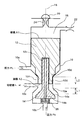
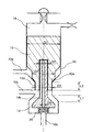
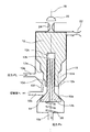
図1,2は、本発明の実施形態に係る方向制御弁の内部構成の概略を示す図である。本実施形態に係る方向制御弁は、以下に説明する弁ボディ10と第1の可動部材12と第2の可動部材14とを備えている。
1 and 2 are diagrams schematically illustrating an internal configuration of a directional control valve according to an embodiment of the present invention. The direction control valve according to the present embodiment includes a
弁ボディ10には、第1の連通切替ポート10aと第2の連通切替ポート10bと連通対象ポート10cとが形成されている。連通切替ポート10aには作動流体の圧力PLが供給され、連通切替ポート10bには作動流体の圧力Pcが供給される。そして、連通対象ポート10cは、切替室(図示せず)に接続されている。ここで、連通切替ポート10bへの供給圧力Pcは、連通切替ポート10aへの供給圧力PLより高く設定されている。また、ここでの作動流体は、非圧縮性流体であり、例えば作動油を用いることもできるし、内燃機関用の燃料を用いることもできる。
The
可動部材12,14は、弁ボディ10の内部でその中心軸16に平行な方向(以下、中心軸方向とする)に移動することで、連通対象ポート10cに連通するポートを連通切替ポート10aと連通切替ポート10bの間で切り替える。連通切替ポート10aと連通対象ポート10cが連通し且つ連通切替ポート10bと連通対象ポート10cの連通が遮断されている場合(図2に示す場合)は、連通切替ポート10aから連通対象ポート10c(切替室)に作動流体の圧力PLが供給される。一方、連通切替ポート10bと連通対象ポート10cが連通し且つ連通切替ポート10aと連通対象ポート10cの連通が遮断されている場合(図1に示す場合)は、連通切替ポート10bから連通対象ポート10c(切替室)に作動流体の圧力Pcが供給される。このように、本実施形態に係る方向制御弁は、連通対象ポート10c(切替室)に連通するポートを、連通切替ポート10aと連通切替ポート10bの間で切り替えることが可能な三方弁である。なお、連通切替ポート10a,10bと連通対象ポート10cの中心軸方向における位置関係は、中心軸方向の一方側(図1,2の上側)から他方側(図1,2の下側)にかけて、連通切替ポート10a、連通対象ポート10c、連通切替ポート10bの順に配置されている。
The
可動部材12は、中心軸方向の一方側へ移動して連通切替ポート10aと連通対象ポート10cを連通させ、中心軸方向の他方側へ移動して連通切替ポート10aと連通対象ポート10cの連通を遮断する。一方、可動部材14は、中心軸方向の他方側へ移動して連通切替ポート10bと連通対象ポート10cを連通させ、中心軸方向の一方側へ移動して連通切替ポート10bと連通対象ポート10cの連通を遮断する。中心軸方向において連通切替ポート10aと連通対象ポート10cの間に位置する弁ボディ10の内周面の径が中心軸方向の一方側から他方側にかけて減少することで第1のシート部10dが形成されており、中心軸方向において連通切替ポート10bと連通対象ポート10cの間に位置する弁ボディ10の内周面の径が中心軸方向の他方側から一方側にかけて減少することで第2のシート部10eが形成されている。このように、シート部10dの中心軸方向における形成位置は、連通切替ポート10aと連通対象ポート10cの間であり、シート部10eの中心軸方向における形成位置は、連通対象ポート10cと連通切替ポート10bの間である。可動部材12には、外周面の径が中心軸方向の一方側から他方側にかけて減少する形状の第1の当接部12aが形成されており、連通切替ポート10aと連通対象ポート10cの連通を遮断するために可動部材12の当接部12aが中心軸方向の一方側からシート部10dに当接する。そして、可動部材12が当接部12aにてシート部10dに当接することで、可動部材12の中心軸方向の他方側への移動が拘束される。一方、可動部材14には、外周面の径が中心軸方向の他方側から一方側にかけて減少する形状の第2の当接部14aが形成されており、連通切替ポート10bと連通対象ポート10cの連通を遮断するために可動部材14の当接部14aが中心軸方向の他方側からシート部10eに当接する。そして、可動部材14が当接部14aにてシート部10eに当接することで、可動部材14の中心軸方向の一方側への移動が拘束される。
The
弁ボディ10の内部における可動部材12よりも中心軸方向の一方側には制御室18が形成されており、供給側オリフィス22を介して制御室18内に供給される作動流体の圧力によって可動部材12に中心軸方向の他方側への推力を作用させることができる。ここで、作動流体の圧力Pcは、連通切替ポート10bの他に、供給側オリフィス22にも供給されている。そして、パイロット弁20の開閉制御によって制御室18内の作動流体の圧力を制御することで、可動部材12に作用させる中心軸方向の他方側への推力を制御することができる。より具体的には、パイロット弁20を閉じて制御室18から排出側オリフィス24を介しての作動流体の排出を遮断することで、制御室18内の圧力がPcに制御され、可動部材12に作用させる中心軸方向の他方側への推力がPc×A1に制御される。ここで、A1は、可動部材12における制御室18内の圧力を中心軸方向の他方側へ受ける面の面積を表す。一方、パイロット弁20を開けて制御室18から排出側オリフィス24を介しての作動流体の排出を許容することで、制御室18内の圧力がPm(Pm<Pc)に制御され、可動部材12に作用させる中心軸方向の他方側への推力がPm×A1に制御される。ここでのパイロット弁20の開閉動作については、例えば電磁力により行うことができ、その駆動力は小さくて済む。そして、圧力Pmの値については、供給側オリフィス22の径、排出側オリフィス24の径、及びパイロット弁20の開度の設定により調整が可能である。なお、排出側オリフィス24は、パイロット弁20が開くときの流路断面積をより正確に設定するために設けられており、排出側オリフィス24を省略することも可能である。
A
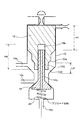
本実施形態では、可動部材12には、中心軸方向の他方側に開口する内挿穴12bが形成されている。内挿穴12bには、可動部材14が中心軸方向の他方側から内挿されており、可動部材14は、内挿穴12bの内側面に対し中心軸方向に摺動可能である。そして、可動部材14には、中心軸方向の一方側及び他方側に開口する貫通穴14bが形成されている。この貫通穴14bにより、内挿穴12b(より具体的には可動部材14が内挿穴12bに内挿されることで形成される空間)と連通切替ポート10bが連通する。ここでの内挿穴12b及び貫通穴14bの中心軸は、可動部材12,14の中心軸16に一致している。可動部材12は、連通切替ポート10bから供給される作動流体の圧力Pcを内挿穴12bの底面12cにて中心軸方向の一方側へ受け、可動部材12には中心軸方向の一方側への力Pc×A3が作用する。ここで、A3は、内挿穴12bの底面12cの面積を表す。また、可動部材12の内挿穴12bの底面12cは、可動部材14に対し中心軸方向の一方側から当接して中心軸方向の他方側への押圧力を作用させることが可能である。さらに、図2に示すように、連通切替ポート10aと連通対象ポート10cが連通し且つ連通切替ポート10bと連通対象ポート10cの連通が遮断された状態では、可動部材12の内挿穴12bの底面12cが可動部材14に対し中心軸方向の一方側へ所定量L0離れるように、可動部材12の内挿穴12bの深さ及び可動部材14の中心軸方向の長さが設定されている。ここでの所定量L0は、可動部材12が中心軸方向に移動するときの行程長(可動部材12のリフト量)L3よりも短く設定されている。そのため、連通切替ポート10aと連通対象ポート10cの連通を遮断し且つ連通切替ポート10bと連通対象ポート10cを連通させるよう可動部材12,14が中心軸方向の他方側へ移動する行程(図2に示す状態から図1に示す状態へ移行する行程)では、可動部材12は、中心軸方向の他方側へ所定量L0移動してから、内挿穴12bの底面12cにて可動部材14に当接して可動部材14を中心軸方向の他方側へ押圧する。そして、押圧された可動部材14は、可動部材12とともに中心軸方向の他方側へ移動する。可動部材14が中心軸方向に移動するときの行程長(可動部材14のリフト量)L1は、L1=L3−L0となり、可動部材12が中心軸方向に移動するときの行程長L3よりも短くなる。
In the present embodiment, the
さらに、本実施形態では、可動部材12における当接部12aよりも中心軸方向の他方側には、連通切替ポート10aと連通対象ポート10cとの間の通路を塞ぐための摺動遮断部12dが設けられている。弁ボディ10には、摺動遮断部12dが嵌合可能な嵌合部10fが中心軸方向においてシート部10dと連通対象ポート10cの間の位置に形成されている。摺動遮断部12dの中心軸方向の長さはL2であり、シート部10dと可動部材12の当接部12aとの距離が所定量L2以下のときに、摺動遮断部12dが中心軸方向の一方側から嵌合部10fに嵌め合わされることで、連通切替ポート10aと連通対象ポート10cとの間の通路が、中心軸方向においてシート部10dと連通対象ポート10cとの間の位置で塞がれる。ここでの所定量(摺動遮断部12dの中心軸方向の長さ)L2は、可動部材14が中心軸方向に移動するときの行程長L1(=L3−L0)よりも長く、且つ可動部材12が中心軸方向に移動するときの行程長L3よりも短く設定されている。また、可動部材12は、連通対象ポート10cから供給される作動流体の圧力Pdを摺動遮断部12dにおける中心軸方向の他方側の端面にて中心軸方向の一方側へ受け、可動部材12には中心軸方向の一方側への力Pd×A2が作用する。ここで、A2は、摺動遮断部12dにおける中心軸方向の他方側の端面の面積を表す。また、可動部材14には、ばね26により中心軸方向の一方側への付勢力Fが作用している。
Furthermore, in the present embodiment, a sliding
また、本実施形態では、以下の(1)〜(3)式が成立するように、ばね26の付勢力F、圧力Pm、及び面積A1,A2,A3の値が設定されている。
In the present embodiment, the urging force F, the pressure Pm, and the areas A1, A2, and A3 of the
Pc×A1>Pc×(A2+A3)+F (1)
Pm×A1<Pc×(A2+A3)+F (2)
Pm×A1<PL×A2+Pc×A3 (3)
Pc × A1> Pc × (A2 + A3) + F (1)
Pm × A1 <Pc × (A2 + A3) + F (2)
Pm × A1 <PL × A2 + Pc × A3 (3)
次に、本実施形態に係る方向制御弁の動作、特に、連通対象ポート10cに連通するポートを連通切替ポート10aと連通切替ポート10bの間で切り替える動作について説明する。本実施形態では、可動部材12に作用させる中心軸方向の他方側の推力を調整することで、連通対象ポート10cに連通するポートを連通切替ポート10aと連通切替ポート10bの間で切り替えることができる。
Next, the operation of the directional control valve according to the present embodiment, particularly the operation of switching the port communicating with the
パイロット弁20が閉じている場合は、制御室18内の圧力がPcに制御されている。ここで、(1)式が成立するようばね26の付勢力F及び面積A1,A2,A3の値が設定されているため、図1に示すように、可動部材12は、推力Pc×A1によって中心軸方向の他方側へ押圧されており、摺動遮断部12dが嵌合部10fに嵌め合わされているとともに、当接部12aがシート部10dに密着している。したがって、連通切替ポート10aと連通対象ポート10cの連通は遮断されている。さらに、前述の所定量L0が、可動部材12が中心軸方向に移動するときの行程長L3よりも短く設定されているため、図1に示すように、可動部材12の当接部12aがシート部10dに密着している状態では、可動部材12の内挿穴12bの底面12cが可動部材14に当接して可動部材14を中心軸方向の他方側へ押圧している。したがって、可動部材14の当接部14aはシート部10eから離れており、連通切替ポート10bと連通対象ポート10cが連通している。以上のように、パイロット弁20が閉じている場合は、連通切替ポート10bと連通対象ポート10cが連通し且つ連通切替ポート10aと連通対象ポート10cの連通が遮断される。その結果、切替室内の圧力はPcとなる。
When the
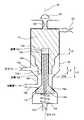
次に、パイロット弁20を開けると、制御室18内の圧力がPcから低下してPmに制御される。ここで、(2)式が成立するようばね26の付勢力F、圧力Pm、及び面積A1,A2,A3の値が設定されているため、可動部材12,14が中心軸方向の一方側へ押圧されて移動し始める。図3に示すように、可動部材14は、ばね26の付勢力Fにより中心軸方向の一方側へ行程長L1移動して、当接部14aにてシート部10eに当接する。これによって、連通切替ポート10bと連通対象ポート10cの連通が遮断される。一方、可動部材12においては、当接部12aがシート部10dから離れても、摺動遮断部12dが嵌合部10fに嵌め合わされている状態では、連通切替ポート10aと連通対象ポート10cとの間の通路が摺動遮断部12dによって塞がれているため、連通切替ポート10aと連通対象ポート10cは連通しない。ここで、摺動遮断部12dの中心軸方向の長さL2が可動部材14の行程長L1よりも長く設定されているため、図3に示すように、可動部材14の当接部14aがシート部10eに当接して連通切替ポート10bと連通対象ポート10cの連通が遮断されても、摺動遮断部12dの一部が嵌合部10fに嵌め合わされている。したがって、連通切替ポート10aと連通対象ポート10cはまだ連通しない。
Next, when the
可動部材14の当接部14aがシート部10eに当接して中心軸方向の一方側への移動が拘束された後においても、可動部材12は弁ボディ10の内周面に対し中心軸方向の一方側へ摺動し続ける。そのため、可動部材12の内挿穴12bの底面12cは、可動部材14に対し中心軸方向の一方側へ離れる。そして、可動部材12の当接部12aがシート部10dに対し中心軸方向の一方側へ所定量L2を超えて離れると、摺動遮断部12dが嵌合部10fから抜けるため、連通切替ポート10aと連通対象ポート10cが連通し始める。さらに、(3)式が成立するよう圧力Pm及び面積A1,A2,A3の値が設定されているため、図2に示すように、可動部材12は中心軸方向の一方側へさらに摺動し続け、連通切替ポート10aと連通対象ポート10cが完全に連通する。このとき、可動部材12の内挿穴12bの底面12cと可動部材14との距離はL0となる。以上のように、パイロット弁20を閉状態から開状態に切り替えることで、連通対象ポート10cに連通するポートを連通切替ポート10bから連通切替ポート10aへ切り替えることができる。その結果、切替室内の圧力をPcからPLへ低下させることができる。
Even after the
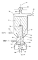
次に、パイロット弁20を閉じると、制御室18内の圧力がPmから増大してPcに制御されるため、可動部材12は、推力Pc×A1によって中心軸方向の他方側へ摺動し始める。一方、可動部材14は、ばね26の付勢力Fにより当接部14aにてシート部10eに密着したままであり、可動部材12の摺動に伴い内挿穴12bの作動流体が貫通穴14bを通って排出される。したがって、可動部材12が中心軸方向の他方側へ摺動し始めても、連通切替ポート10bと連通対象ポート10cはまだ連通しない。ここで、摺動遮断部12dの中心軸方向の長さL2が可動部材14の行程長L1(=L3−L0)よりも長く設定されているため、シート部10dと可動部材12の当接部12aとの距離が所定量L2よりも短くなり摺動遮断部12dが嵌合部10fに嵌合し始めても、可動部材12の中心軸方向の他方側への移動量は所定量L0よりも短く、内挿穴12bの底面12cは可動部材14にまだ当接しない。したがって、連通切替ポート10bと連通対象ポート10cが連通する前に、連通切替ポート10aと連通対象ポート10cの連通が摺動遮断部12dにより遮断される。
Next, when the
摺動遮断部12dが嵌合部10fに嵌合し始めた後に、可動部材12の中心軸方向の他方側への移動量が所定量L0に達すると、図4に示すように、可動部材12の内挿穴12bの底面12cが可動部材14に当接する。そして、可動部材12は、内挿穴12bの底面12cにて可動部材14を中心軸方向の他方側へ押圧し、可動部材14は、可動部材12とともに中心軸方向の他方側へ移動する。これによって、図1に示すように、可動部材14の当接部14aがシート部10eから離れ、連通切替ポート10bと連通対象ポート10cが連通する。可動部材12,14の中心軸方向の他方側への移動は、可動部材12の当接部12aがシート部10dに当接するまで続いて行われる。以上のように、パイロット弁20を開状態から閉状態に切り替えることで、連通対象ポート10cに連通するポートを連通切替ポート10aから連通切替ポート10bへ切り替えることができる。その結果、切替室内の圧力をPLからPcへ増大させることができる。
When the movement amount of the
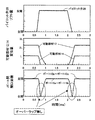
次に、本願発明者が行った解析の結果について説明する。 Next, the results of analysis performed by the inventor will be described.
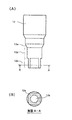
解析対象とする方向制御弁の仕様については以下の通りである。図5,6に示すように、可動部材12の寸法については、制御室18内の圧力を受ける部分の直径D1はd(dは定数)、連通切替ポート10aと連通対象ポート10cの間の通路を形成する部分の直径D2は0.9×d、摺動遮断部12dの直径D3は0.8d、摺動遮断部12dの中心軸方向の長さL2は1.2×L(Lは定数)、内挿穴12bの直径D4は0.5×d、内挿穴12bの深さ(摺動長)H4は80×L、直径D1(=d)の部分における弁ボディ10の内周面に対する摺動長H1は46×Lである。また、可動部材14の寸法については、貫通穴14bの直径は0.2×dである。また、可動部材12が中心軸方向に移動するときの行程長(可動部材12のリフト量)L3は2.2×L、可動部材14が中心軸方向に移動するときの行程長(可動部材14のリフト量)L1はLである。また、可動部材12の当接部12aがシート部10dに当接している状態におけるばね26のプリロードは30[N]である。
The specifications of the directional control valve to be analyzed are as follows. As shown in FIGS. 5 and 6, regarding the dimensions of the
以上説明した仕様の方向制御弁の動作を市販の汎用計算ソフトを用いて計算した結果を図7に示す。ここで、図7の上段はパイロット弁20のリフト量の時系列波形を示し、図7の中段は可動部材12,14の中心軸方向に関する変位量(パイロット弁20が全開のときを変位量0とする)の時系列波形を示し、図7の下段は連通切替ポート10a〜連通対象ポート10c間及び連通切替ポート10b〜連通対象ポート10c間の開口面積の時系列波形を示す。図7に示すように、パイロット弁20を全閉から全開に切り替える場合、及びパイロット弁20を全開から全閉に切り替える場合の両方において、連通切替ポート10a,10bの両方が連通対象ポート10cに同時に連通するのを防止(開口面積のオーバーラップを防止)できていることがわかる。
FIG. 7 shows the result of calculating the operation of the directional control valve having the specifications described above using commercially available general-purpose calculation software. Here, the upper part of FIG. 7 shows a time-series waveform of the lift amount of the
以上説明した本実施形態によれば、連通切替ポート10aと連通対象ポート10cの連通を遮断し且つ連通切替ポート10bと連通対象ポート10cを連通させるよう可動部材12,14が中心軸方向の他方側へ移動する行程では、可動部材12は、中心軸方向の他方側へ所定量L0移動してから、内挿穴12bの底面12cにて可動部材14に当接して可動部材14を中心軸方向の他方側へ押圧する。これによって、可動部材12の移動開始時期に対して、可動部材14の移動開始時期、すなわち連通切替ポート10bと連通対象ポート10cの連通開始時期を遅らせることができるので、連通切替ポート10a,10bの両方が連通対象ポート10cに同時に連通するのを抑制することができる。その結果、連通対象ポート10cに連通するポートを連通切替ポート10aから連通切替ポート10bへ切り替える際に、高圧側の連通切替ポート110bへ供給された作動流体が低圧側の連通切替ポート110aへ流出するのを抑制することができ、作動流体のエネルギー損失を低減することができる。
According to the embodiment described above, the
さらに、本実施形態では、可動部材12の内挿穴12bの底面12cが可動部材14に当接する前に、摺動遮断部12dが嵌合部10fに内挿されることで連通切替ポート10aと連通対象ポート10cとの間の通路が塞がれる。そのため、連通切替ポート10aと連通対象ポート10cの連通が遮断された後に、連通切替ポート10bと連通対象ポート10cが連通する。すなわち、連通切替ポート10a,10bの両方が連通対象ポート10cに同時に連通するのが防止される。その結果、連通対象ポート10cに連通するポートを連通切替ポート10aから連通切替ポート10bへ切り替える際に生じる作動流体のエネルギー損失を無くすことができる。
Furthermore, in this embodiment, before the
また、本実施形態によれば、連通切替ポート10bと連通対象ポート10cの連通を遮断し且つ連通切替ポート10aと連通対象ポート10cを連通させるよう可動部材12,14が中心軸方向の一方側へ移動する行程では、摺動遮断部12dは、当接部12aがシート部10dに対し中心軸方向の一方側へ所定量L2を超えて離れてから、連通切替ポート10aと連通対象ポート10cを連通させる。これによって、可動部材14の移動開始時期に対して、連通切替ポート10aと連通対象ポート10cの連通開始時期を遅らせることができるので、連通切替ポート10a,10bの両方が連通対象ポート10cに同時に連通するのを抑制することができる。その結果、連通対象ポート10cに連通するポートを連通切替ポート10bから連通切替ポート10aへ切り替える際に生じる作動流体のエネルギー損失を低減することができる。
Further, according to the present embodiment, the
さらに、本実施形態では、摺動遮断部12dの中心軸方向の長さL2が可動部材14の行程長L1よりも長く設定されていることで、可動部材14の当接部14aがシート部10eに当接した後に、摺動遮断部12dが嵌合部10fから抜ける。そのため、連通切替ポート10bと連通対象ポート10cの連通が遮断された後に、連通切替ポート10aと連通対象ポート10cが連通する。すなわち、連通切替ポート10a,10bの両方が連通対象ポート10cに同時に連通するのが防止される。その結果、連通対象ポート10cに連通するポートを連通切替ポート10bから連通切替ポート10aへ切り替える際に生じる作動流体のエネルギー損失を無くすことができる。
Furthermore, in the present embodiment, the length L2 of the sliding blocking
以上のように、本実施形態によれば、連通対象ポート10cに連通するポートを連通切替ポート10aから連通切替ポート10bへ切り替える場合と連通切替ポート10bから連通切替ポート10aへ切り替える場合の両方において、連通切替ポート10a,10bの両方が連通対象ポート10cに同時に連通するのを防止することができ、作動流体のエネルギー損失を無くすことができる。
As described above, according to the present embodiment, in both the case of switching the port communicating with the
次に、本実施形態の他の構成例について説明する。 Next, another configuration example of this embodiment will be described.
以上の説明では、摺動遮断部12dを可動部材12に設けるものとしたが、本実施形態では、摺動遮断部12dを可動部材14における当接部14aよりも中心軸方向の一方側に設けることもできる。その場合は、摺動遮断部12dの中心軸方向の長さL2を、可動部材14が中心軸方向に移動するときの行程長L1よりも短く設定する。これによって、連通切替ポート10a,10bの両方が同時に開く期間を短縮することができ、作動流体のエネルギー損失を大幅に減少することができる。
In the above description, the sliding blocking
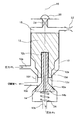
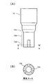
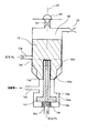
また、図8に示す構成例では、図1,2に示す構成例と比較して、可動部材12における摺動遮断部12dよりも中心軸方向の他方側に摺動案内部12eが設けられている。ここで、図8(A)は可動部材12の側面図を示し、図8(B)は図8(A)のA−A断面図を示す。摺動案内部12eは、嵌合部10fに対し中心軸方向に摺動可能であり、さらに、嵌合部10fに嵌め合わされたときに嵌合部10fとの間に連通切替ポート10aと連通対象ポート10cを連通させるための通路が形成されるよう、その外周面に中心軸方向に延伸する溝が複数形成されている。そのため、図9に示すように、シート部10dと可動部材12の当接部12aとの距離が所定量L2よりも長くなり摺動遮断部12dが嵌合部10fから抜けたときには、摺動案内部12eは、嵌合部10fに対し接触しながら連通切替ポート10aと連通対象ポート10cを連通させる。
Further, in the configuration example shown in FIG. 8, compared to the configuration examples shown in FIGS. 1 and 2, the sliding
図1,2に示す構成例では、連通切替ポート10aと連通対象ポート10cが連通しているときは、可動部材12(摺動遮断部12d)が嵌合部10fから完全に抜けている。そのため、可動部材12が中心軸方向の他方側へ移動する行程において摺動遮断部12dが嵌合部10fに内挿されるときに引っ掛かりが生じる可能性があり、可動部材12の滑らかな摺動が妨げられる可能性がある。これに対して図8に示す構成例では、連通切替ポート10aと連通対象ポート10cが連通しているときでも、図9に示すように、可動部材12(摺動案内部12e)が嵌合部10fに内挿されて接触している。そのため、可動部材12が中心軸方向の他方側へ移動する行程において摺動遮断部12dが嵌合部10fに内挿されるときに引っ掛かりが生じるのを抑止することができる。したがって、可動部材12の滑らかな摺動を実現することができる。
In the configuration example shown in FIGS. 1 and 2, when the
なお、摺動案内部12eの外周面に形成する溝の形状については、図8に示す形状に限るものではなく、例えば図10に示すように、周方向に延伸する溝をさらに形成することもできる。ここで、図10(A)は可動部材12の側面図を示し、図10(B)は可動部材12(摺動案内部12e)の下面図を示す。さらに、例えば図11に示すように、摺動案内部12eの外周面の一部が削り取られていることによっても、連通切替ポート10aと連通対象ポート10cを連通させるための通路を形成することができる。ここで、図11(A)は可動部材12の側面図を示し、図11(B)は図11(A)のA−A断面図を示す。さらに、摺動遮断部12dを可動部材14の方に設ける場合は、摺動案内部12eを可動部材14における摺動遮断部12dよりも中心軸方向の他方側に設けることもできる。
The shape of the groove formed on the outer peripheral surface of the sliding
また、図12に示す構成例では、図1,2に示す構成例と比較して、連通切替ポート10aと連通対象ポート10cとの間の通路を塞ぐための摺動遮断部12dが可動部材12における当接部12aよりも中心軸方向の一方側に配設されている。そして、シート部10dと当接部12aの距離が所定量L2以下のときに摺動遮断部12dが嵌め合わされる嵌合部10fが中心軸方向において連通切替ポート10aとシート部10dとの間に配設されている。ここでの摺動遮断部12dは、その直径が可動部材12の弁ボディ10に対する摺動径(可動部材12の最大直径)に等しく設定されており、連通切替ポート10aと連通対象ポート10cとの間の通路を、中心軸方向において連通切替ポート10aとシート部10dとの間の位置で塞ぐ。さらに、弁ボディ10には、シート部10eとして中心軸方向(中心軸16)に垂直な平面が形成されており、可動部材14には、当接部14aとして中心軸方向に垂直な(シート部10eの平面に平行な)平面が形成されている。
In the configuration example shown in FIG. 12, compared to the configuration examples shown in FIGS. 1 and 2, the sliding blocking
図1,2に示す構成例では、摺動遮断部12dの直径が可動部材12の弁ボディ10に対する摺動径(最大直径)よりも小さく、可動部材12は、弁ボディ10に対し最大直径部分と摺動遮断部12dの直径の異なる2つの部分にて摺動する。そのため、これら2つの摺動部分と当接部12aの3箇所に同芯であることが要求される。さらに、可動部材14の当接部14aとも同軸であることが要求される。したがって、可動部材12,14の加工に高い精度が要求される。これに対して図12に示す構成例では、摺動遮断部12dの直径が可動部材12の弁ボディ10に対する摺動径(最大直径)に等しいため、可動部材12の摺動部分の同芯加工を無くすことができる。さらに、弁ボディ10のシート部10eと可動部材14の当接部14aがともに中心軸方向に垂直な平面となるため、可動部材12に対する可動部材14の当接部14aの同軸が不要となる。したがって、可動部材12,14の寸法公差を大きくするのを許容することができる。
In the configuration example shown in FIGS. 1 and 2, the diameter of the sliding blocking
以上の本実施形態の説明では、パイロット弁20の開閉制御により制御室18内の圧力を制御することで、可動部材12に作用させる推力を制御するものとした。ただし、本実施形態では、パイロット弁20の開閉制御以外の手段によっても可動部材12に作用させる推力を制御することができ、例えば可動部材12に作用させる推力を電磁力により直接制御することも可能である。
In the above description of the present embodiment, the thrust applied to the
以上、本発明を実施するための形態について説明したが、本発明はこうした実施形態に何等限定されるものではなく、本発明の要旨を逸脱しない範囲内において、種々なる形態で実施し得ることは勿論である。 As mentioned above, although the form for implementing this invention was demonstrated, this invention is not limited to such embodiment at all, and it can implement with a various form in the range which does not deviate from the summary of this invention. Of course.
10 弁ボディ、10a,10b 連通切替ポート、10c 連通対象ポート、10d,10e シート部、10f 嵌合部、12,14 可動部材、12a,14a 当接部、12b 内挿穴、12c 底面、12d 摺動遮断部、12e 摺動案内部、14b 貫通穴、18 制御室、20 パイロット弁、26 ばね。 10 valve body, 10a, 10b communication switching port, 10c communication target port, 10d, 10e seat portion, 10f fitting portion, 12, 14 movable member, 12a, 14a abutting portion, 12b insertion hole, 12c bottom surface, 12d sliding Dynamic blocking part, 12e Sliding guide part, 14b Through hole, 18 Control chamber, 20 Pilot valve, 26 Spring.
Claims (11)
可動部材は、
中心軸方向の一方側へ移動して第1連通切替ポートと連通対象ポートを連通させ、中心軸方向の他方側へ移動して第1連通切替ポートと連通対象ポートの連通を遮断する第1可動部材と、
中心軸方向の他方側へ移動して第2連通切替ポートと連通対象ポートを連通させ、中心軸方向の一方側へ移動して第2連通切替ポートと連通対象ポートの連通を遮断する第2可動部材と、
を含み、
弁ボディには、第1連通切替ポートと連通対象ポートの連通を遮断するために第1可動部材が中心軸方向の一方側から当接する第1シート部と、第2連通切替ポートと連通対象ポートの連通を遮断するために第2可動部材が中心軸方向の他方側から当接する第2シート部と、が設けられており、
第1可動部材には、第2可動部材に対し中心軸方向の一方側から当接して中心軸方向の他方側への押圧力を作用させることが可能な押圧部と、第1シート部に対し中心軸方向の一方側から当接可能な第1当接部と、が設けられており、
押圧部は、第1連通切替ポートと連通対象ポートが連通し且つ第2連通切替ポートと連通対象ポートの連通が遮断された状態では、第2可動部材に対し中心軸方向の一方側へ第1所定量離れており、
第1可動部材に作用する中心軸方向の他方側への推力により第1連通切替ポートと連通対象ポートの連通を遮断し且つ第2連通切替ポートと連通対象ポートを連通させるよう第1及び第2可動部材が中心軸方向の他方側へ移動する行程では、第1可動部材は、中心軸方向の他方側へ第1所定量移動してから、押圧部にて第2可動部材を中心軸方向の他方側へ押圧し、
第1可動部材または第2可動部材には、第1シート部と第1当接部の距離が第2所定量以下のときに第1連通切替ポートと連通対象ポートとの間の通路を塞ぐ遮断部が設けられており、
第2連通切替ポートと連通対象ポートの連通を遮断し且つ第1連通切替ポートと連通対象ポートを連通させるよう第1及び第2可動部材が中心軸方向の一方側へ移動する行程では、遮断部は、第1当接部が第1シート部に対し中心軸方向の一方側へ第2所定量を超えて離れてから、第1連通切替ポートと連通対象ポートを連通させることを特徴とする方向制御弁。 The valve body in which the first and second communication switching ports and the communication target port are formed, and the port that moves in the central axis direction within the valve body and communicates with the communication target port are switched to the first communication switching port and the second communication switching. A directional control valve comprising a movable member that switches between ports,
The movable member is
Move to one side in the central axis direction to connect the first communication switching port and the communication target port, and move to the other side in the central axis direction to block communication between the first communication switching port and the communication target port Members,
A second movable member that moves to the other side in the central axis direction to connect the second communication switching port and the communication target port, and moves to one side in the central axis direction to block communication between the second communication switching port and the communication target port. Members,
Including
The valve body includes a first seat portion with which the first movable member abuts from one side in the central axis direction to block communication between the first communication switching port and the communication target port, a second communication switching port, and a communication target port. The second movable member is in contact with the second movable member from the other side in the central axis direction,
The first movable member has a pressing portion capable of contacting the second movable member from one side in the central axis direction and applying a pressing force to the other side in the central axis direction, and the first sheet portion A first abutting portion capable of abutting from one side in the central axis direction is provided,
In the state where the first communication switching port and the communication target port communicate with each other and the communication between the second communication switching port and the communication target port is blocked, the pressing portion is first to the one side in the central axis direction with respect to the second movable member. A certain amount away,
First and second so as to block communication between the first communication switching port and the communication target port and to communicate between the second communication switching port and the communication target port by thrust toward the other side in the central axis direction acting on the first movable member. In the stroke in which the movable member moves to the other side in the central axis direction, the first movable member moves the first predetermined amount to the other side in the central axis direction and then moves the second movable member in the central axis direction at the pressing portion. Press to the other side ,
The first movable member or the second movable member is blocked by blocking a passage between the first communication switching port and the communication target port when the distance between the first sheet portion and the first contact portion is a second predetermined amount or less. Part is provided,
In the stroke in which the first and second movable members move to one side in the central axis direction so as to block the communication between the second communication switching port and the communication target port and to connect the first communication switching port and the communication target port. Is a direction in which the first communication switching port and the communication target port are communicated with each other after the first abutting portion is separated from the first seat portion toward the one side in the central axis direction by a second predetermined amount. Control valve.
弁ボディには、第1シート部と第1当接部の距離が第2所定量以下のときに遮断部が嵌め合わされる嵌合部が設けられており、
遮断部が嵌合部に嵌め合わされることで第1連通切替ポートと連通対象ポートとの間の通路が塞がれることを特徴とする方向制御弁。 The directional control valve according to claim 1,
The valve body is provided with a fitting portion into which the blocking portion is fitted when the distance between the first seat portion and the first contact portion is equal to or less than the second predetermined amount ,
A direction control valve characterized in that the passage between the first communication switching port and the communication target port is closed by fitting the blocking portion to the fitting portion .
第1可動部材または第2可動部材には、第1シート部と第1当接部の距離が第2所定量より長いときに嵌合部に対し接触しながら第1連通切替ポートと連通対象ポートを連通させる摺動案内部が設けられていることを特徴とする方向制御弁。 A directional control valve according to claim 2,
The first movable member or the second movable member includes a first communication switching port and a communication target port while contacting the fitting portion when the distance between the first sheet portion and the first contact portion is longer than a second predetermined amount. A directional control valve characterized in that a sliding guide part is provided for communicating with each other .
第1シート部は、中心軸方向において第1連通切替ポートと連通対象ポートとの間に設けられており、
遮断部は、第1連通切替ポートと連通対象ポートとの間の通路を、中心軸方向において第1シート部と連通対象ポートとの間で塞ぐことを特徴とする方向制御弁。 The direction control valve according to any one of claims 1 to 3 ,
The first seat portion is provided between the first communication switching port and the communication target port in the central axis direction.
The blocking part closes the passage between the first communication switching port and the communication target port between the first seat part and the communication target port in the central axis direction .
第1シート部は、中心軸方向において第1連通切替ポートと連通対象ポートとの間に設けられており、
遮断部は、第1連通切替ポートと連通対象ポートとの間の通路を、中心軸方向において第1連通切替ポートと第1シート部との間で塞ぐことを特徴とする方向制御弁。 The direction control valve according to any one of claims 1 to 4 ,
The first seat portion is provided between the first communication switching port and the communication target port in the central axis direction.
The blocking unit closes a passage between the first communication switching port and the communication target port between the first communication switching port and the first seat portion in the central axis direction .
遮断部の径が、第1可動部材の弁ボディに対する摺動径に等しく設定されていることを特徴とする方向制御弁。 The direction control valve according to any one of claims 1 to 5,
A direction control valve characterized in that the diameter of the blocking portion is set equal to the sliding diameter of the first movable member relative to the valve body .
遮断部は、第1可動部材に設けられており、
第2所定量は、第2可動部材が中心軸方向に移動するときの行程長より長く設定されていることを特徴とする方向制御弁。 The direction control valve according to any one of claims 1 to 6,
The blocking part is provided on the first movable member,
The second predetermined amount is set to be longer than a stroke length when the second movable member moves in the central axis direction .
第2可動部材には、第2シート部に対し中心軸方向の他方側から当接可能な第2当接部が設けられており、
弁ボディには、第2シート部として中心軸方向に垂直な平面が形成されており、
第2可動部材には、第2当接部として中心軸方向に垂直な平面が形成されていることを特徴とする方向制御弁。 The directional control valve according to any one of claims 1 to 7,
The second movable member is provided with a second contact portion that can contact the second sheet portion from the other side in the central axis direction,
The valve body is formed with a plane perpendicular to the central axis direction as the second seat portion,
A direction control valve characterized in that the second movable member is formed with a plane perpendicular to the central axis direction as a second contact portion .
第1可動部材には、中心軸方向の他方側から第2可動部材が内挿される内挿穴が形成されており、
押圧部が、この内挿穴の底面により構成されることを特徴とする方向制御弁。 The direction control valve according to any one of claims 1 to 8,
The first movable member is formed with an insertion hole into which the second movable member is inserted from the other side in the central axis direction.
A directional control valve , wherein the pressing portion is constituted by a bottom surface of the insertion hole .
第2可動部材には、第2連通切替ポートと内挿穴を連通させるための貫通穴が形成されていることを特徴とする方向制御弁。 The directional control valve according to claim 9 ,
The second movable member is formed with a through hole for communicating the second communication switching port with the insertion hole .
第2可動部材に中心軸方向の一方側への付勢力を作用させる付勢手段が設けられており、
第1可動部材に作用させる中心軸方向の他方側への推力を調整することで、連通対象ポートに連通するポートを第1連通切替ポートと第2連通切替ポートの間で切り替えることを特徴とする方向制御弁。 The direction control valve according to any one of claims 1 to 10,
An urging means for applying an urging force to one side in the central axis direction on the second movable member is provided,
The port communicating with the communication target port is switched between the first communication switching port and the second communication switching port by adjusting the thrust to the other side in the central axis direction applied to the first movable member. Directional control valve.
Priority Applications (3)
| Application Number | Priority Date | Filing Date | Title |
|---|---|---|---|
| JP2005222162A JP4695453B2 (en) | 2005-07-29 | 2005-07-29 | Directional control valve |
| DE102006000376.4A DE102006000376B4 (en) | 2005-07-29 | 2006-07-28 | Directional control valve |
| US11/494,796 US7784492B2 (en) | 2005-07-29 | 2006-07-28 | Direction control valve |
Applications Claiming Priority (1)
| Application Number | Priority Date | Filing Date | Title |
|---|---|---|---|
| JP2005222162A JP4695453B2 (en) | 2005-07-29 | 2005-07-29 | Directional control valve |
Publications (2)
| Publication Number | Publication Date |
|---|---|
| JP2007040323A JP2007040323A (en) | 2007-02-15 |
| JP4695453B2 true JP4695453B2 (en) | 2011-06-08 |
Family
ID=37650461
Family Applications (1)
| Application Number | Title | Priority Date | Filing Date |
|---|---|---|---|
| JP2005222162A Expired - Fee Related JP4695453B2 (en) | 2005-07-29 | 2005-07-29 | Directional control valve |
Country Status (3)
| Country | Link |
|---|---|
| US (1) | US7784492B2 (en) |
| JP (1) | JP4695453B2 (en) |
| DE (1) | DE102006000376B4 (en) |
Families Citing this family (6)
| Publication number | Priority date | Publication date | Assignee | Title |
|---|---|---|---|---|
| JP4506744B2 (en) * | 2006-11-20 | 2010-07-21 | 株式会社デンソー | Three-way switching valve and injector provided with the same |
| US8606281B2 (en) * | 2007-04-26 | 2013-12-10 | Nokia Corporation | System and method for requesting uplink resources in a communication system |
| GB2451695B (en) * | 2007-08-10 | 2011-09-21 | Honeywell Normalair Garrett Ltd | Fluid control valve |
| DE102008014250A1 (en) * | 2008-03-13 | 2009-09-17 | Man Diesel Se | Fuel supply system of an internal combustion engine |
| DE102009059900A1 (en) * | 2009-12-21 | 2011-06-22 | Knorr-Bremse Systeme für Nutzfahrzeuge GmbH, 80809 | Valve means, electrically operated parking brake system and method of controlling an electrically actuated parking brake system |
| DE102013107389B4 (en) * | 2013-07-12 | 2023-06-01 | Svm Schultz Verwaltungs-Gmbh & Co. Kg | pressure control valve |
Family Cites Families (18)
| Publication number | Priority date | Publication date | Assignee | Title |
|---|---|---|---|---|
| DE538705C (en) * | 1931-11-20 | Edmund Uher Jun | Piston valve with cover | |
| US2606739A (en) * | 1948-04-30 | 1952-08-12 | Lawrence H Gardner | Fluid control valve |
| GB1009729A (en) * | 1962-05-12 | 1965-11-10 | Charles Louis William Abegglen | Valve devices for controlling liquids |
| US3521852A (en) * | 1966-12-12 | 1970-07-28 | Thomas S Gillis Jr | Throttle and shutoff valve |
| US4067357A (en) * | 1974-06-14 | 1978-01-10 | Herion-Werke Kg | Pilot-operated directional control valve |
| US4454892A (en) * | 1982-09-13 | 1984-06-19 | Combustion Engineering, Inc. | Atomizing oil valve improvement |
| US5558125A (en) * | 1994-09-06 | 1996-09-24 | Ingersoll-Rand Company | Air winch control valve |
| JPH08184382A (en) * | 1994-12-29 | 1996-07-16 | Smc Corp | Poppet type direction switching valve |
| DE19504364C2 (en) * | 1995-02-10 | 1998-08-27 | Festo Ag & Co | Pressure control valve |
| JPH0989142A (en) * | 1995-09-27 | 1997-03-31 | Smc Corp | Direct-acting electromagnetic valve |
| DE19910970A1 (en) | 1999-03-12 | 2000-09-28 | Bosch Gmbh Robert | Fuel injector |
| JP3452850B2 (en) * | 1999-09-22 | 2003-10-06 | 株式会社日本自動車部品総合研究所 | Injection valve for internal combustion engine |
| JP2002227747A (en) * | 2001-01-31 | 2002-08-14 | Denso Corp | Control valve and fuel injection valve provided with the same |
| DE10141110A1 (en) * | 2001-08-22 | 2003-03-20 | Bosch Gmbh Robert | Fuel injection device for internal combustion engines |
| JP2003343744A (en) * | 2002-05-29 | 2003-12-03 | Ckd Corp | Switching valve for high temperature fluid |
| DE10229419A1 (en) * | 2002-06-29 | 2004-01-29 | Robert Bosch Gmbh | Pressure-translated fuel injector with rapid pressure reduction at the end of injection |
| JP3994871B2 (en) * | 2002-12-19 | 2007-10-24 | いすゞ自動車株式会社 | Pressure proportional control valve |
| JP4286770B2 (en) * | 2004-12-02 | 2009-07-01 | 株式会社日本自動車部品総合研究所 | Control valve and fuel injection valve having the same |
-
2005
- 2005-07-29 JP JP2005222162A patent/JP4695453B2/en not_active Expired - Fee Related
-
2006
- 2006-07-28 DE DE102006000376.4A patent/DE102006000376B4/en not_active Expired - Fee Related
- 2006-07-28 US US11/494,796 patent/US7784492B2/en not_active Expired - Fee Related
Also Published As
| Publication number | Publication date |
|---|---|
| US7784492B2 (en) | 2010-08-31 |
| US20070023092A1 (en) | 2007-02-01 |
| JP2007040323A (en) | 2007-02-15 |
| DE102006000376B4 (en) | 2016-11-24 |
| DE102006000376A1 (en) | 2007-02-01 |
Similar Documents
| Publication | Publication Date | Title |
|---|---|---|
| EP2094949B1 (en) | Dual lift rocker arm latch mechanism andactuation arrangement therefor | |
| JP5483567B2 (en) | Relief valve with relief pressure change function | |
| JP4695453B2 (en) | Directional control valve | |
| KR20140045541A (en) | Slide valve having a valve slide | |
| KR20020020852A (en) | Relief valve | |
| EP3002463B1 (en) | Aircraft hydraulic valve | |
| JP5561528B2 (en) | Relief valve with relief pressure change function | |
| JP4463028B2 (en) | Spool valve | |
| CN212028216U (en) | Hydraulic control valve and variable displacement hydraulic pump with hydraulic control valve | |
| JPH0419483A (en) | Electromagnetic switching valve | |
| KR20150127754A (en) | Valve arrangement, particularly in an automatic transmission of a motor vehicle | |
| KR100965041B1 (en) | Actuator control unit | |
| US20140137968A1 (en) | Hydraulic pressure control valve | |
| EP2689142B1 (en) | Valve | |
| KR20140080438A (en) | Slide valve, especially for controlling the automatic gearbox of a vehicle | |
| JP2013221614A (en) | Hydraulic control valve and hydraulic control device | |
| CN116265792B (en) | Electrohydraulic quick-break valve | |
| JP2510475Y2 (en) | Solenoid pressure control valve | |
| JP2017020562A (en) | Relief valve | |
| CN223524397U (en) | Gear shifting assembly | |
| JPH0722499Y2 (en) | Clutch actuation circuit with electromagnetic proportional pressure control valve | |
| JP5826145B2 (en) | Variable valve operating device for internal combustion engine | |
| JPWO2013108352A1 (en) | Hydraulic control circuit | |
| JP4695004B2 (en) | Clutch hydraulic control device for torque converter with transmission | |
| CN113530904A (en) | Hydraulic control valve and variable displacement hydraulic pump with hydraulic control valve |
Legal Events
| Date | Code | Title | Description |
|---|---|---|---|
| A621 | Written request for application examination |
Free format text: JAPANESE INTERMEDIATE CODE: A621 Effective date: 20071120 |
|
| A977 | Report on retrieval |
Free format text: JAPANESE INTERMEDIATE CODE: A971007 Effective date: 20100715 |
|
| A131 | Notification of reasons for refusal |
Free format text: JAPANESE INTERMEDIATE CODE: A131 Effective date: 20100810 |
|
| A521 | Request for written amendment filed |
Free format text: JAPANESE INTERMEDIATE CODE: A523 Effective date: 20100921 |
|
| TRDD | Decision of grant or rejection written | ||
| A01 | Written decision to grant a patent or to grant a registration (utility model) |
Free format text: JAPANESE INTERMEDIATE CODE: A01 Effective date: 20110222 |
|
| A01 | Written decision to grant a patent or to grant a registration (utility model) |
Free format text: JAPANESE INTERMEDIATE CODE: A01 |
|
| A61 | First payment of annual fees (during grant procedure) |
Free format text: JAPANESE INTERMEDIATE CODE: A61 Effective date: 20110225 |
|
| FPAY | Renewal fee payment (event date is renewal date of database) |
Free format text: PAYMENT UNTIL: 20140304 Year of fee payment: 3 |
|
| R150 | Certificate of patent or registration of utility model |
Ref document number: 4695453 Country of ref document: JP Free format text: JAPANESE INTERMEDIATE CODE: R150 Free format text: JAPANESE INTERMEDIATE CODE: R150 |
|
| S531 | Written request for registration of change of domicile |
Free format text: JAPANESE INTERMEDIATE CODE: R313532 |
|
| FPAY | Renewal fee payment (event date is renewal date of database) |
Free format text: PAYMENT UNTIL: 20140304 Year of fee payment: 3 |
|
| R350 | Written notification of registration of transfer |
Free format text: JAPANESE INTERMEDIATE CODE: R350 |
|
| R250 | Receipt of annual fees |
Free format text: JAPANESE INTERMEDIATE CODE: R250 |
|
| R250 | Receipt of annual fees |
Free format text: JAPANESE INTERMEDIATE CODE: R250 |
|
| R250 | Receipt of annual fees |
Free format text: JAPANESE INTERMEDIATE CODE: R250 |
|
| R250 | Receipt of annual fees |
Free format text: JAPANESE INTERMEDIATE CODE: R250 |
|
| R250 | Receipt of annual fees |
Free format text: JAPANESE INTERMEDIATE CODE: R250 |
|
| R250 | Receipt of annual fees |
Free format text: JAPANESE INTERMEDIATE CODE: R250 |
|
| LAPS | Cancellation because of no payment of annual fees |