JP4693363B2 - Television apparatus and control method thereof - Google Patents
Television apparatus and control method thereof Download PDFInfo
- Publication number
- JP4693363B2 JP4693363B2 JP2004131410A JP2004131410A JP4693363B2 JP 4693363 B2 JP4693363 B2 JP 4693363B2 JP 2004131410 A JP2004131410 A JP 2004131410A JP 2004131410 A JP2004131410 A JP 2004131410A JP 4693363 B2 JP4693363 B2 JP 4693363B2
- Authority
- JP
- Japan
- Prior art keywords
- electronic device
- data
- unit
- control
- storage unit
- Prior art date
- Legal status (The legal status is an assumption and is not a legal conclusion. Google has not performed a legal analysis and makes no representation as to the accuracy of the status listed.)
- Expired - Fee Related
Links
Images


Classifications
-
- H—ELECTRICITY
- H04—ELECTRIC COMMUNICATION TECHNIQUE
- H04H—BROADCAST COMMUNICATION
- H04H60/00—Arrangements for broadcast applications with a direct linking to broadcast information or broadcast space-time; Broadcast-related systems
- H04H60/09—Arrangements for device control with a direct linkage to broadcast information or to broadcast space-time; Arrangements for control of broadcast-related services
- H04H60/13—Arrangements for device control affected by the broadcast information
-
- H—ELECTRICITY
- H04—ELECTRIC COMMUNICATION TECHNIQUE
- H04N—PICTORIAL COMMUNICATION, e.g. TELEVISION
- H04N21/00—Selective content distribution, e.g. interactive television or video on demand [VOD]
- H04N21/40—Client devices specifically adapted for the reception of or interaction with content, e.g. set-top-box [STB]; Operations thereof
- H04N21/43—Processing of content or additional data, e.g. demultiplexing additional data from a digital video stream; Elementary client operations, e.g. monitoring of home network or synchronising decoder's clock; Client middleware
- H04N21/436—Interfacing a local distribution network, e.g. communicating with another STB or one or more peripheral devices inside the home
-
- H—ELECTRICITY
- H04—ELECTRIC COMMUNICATION TECHNIQUE
- H04H—BROADCAST COMMUNICATION
- H04H20/00—Arrangements for broadcast or for distribution combined with broadcast
- H04H20/28—Arrangements for simultaneous broadcast of plural pieces of information
-
- H—ELECTRICITY
- H04—ELECTRIC COMMUNICATION TECHNIQUE
- H04H—BROADCAST COMMUNICATION
- H04H20/00—Arrangements for broadcast or for distribution combined with broadcast
- H04H20/86—Arrangements characterised by the broadcast information itself
- H04H20/91—Arrangements characterised by the broadcast information itself broadcasting computer programmes
-
- H—ELECTRICITY
- H04—ELECTRIC COMMUNICATION TECHNIQUE
- H04H—BROADCAST COMMUNICATION
- H04H60/00—Arrangements for broadcast applications with a direct linking to broadcast information or broadcast space-time; Broadcast-related systems
- H04H60/09—Arrangements for device control with a direct linkage to broadcast information or to broadcast space-time; Arrangements for control of broadcast-related services
-
- H—ELECTRICITY
- H04—ELECTRIC COMMUNICATION TECHNIQUE
- H04H—BROADCAST COMMUNICATION
- H04H60/00—Arrangements for broadcast applications with a direct linking to broadcast information or broadcast space-time; Broadcast-related systems
- H04H60/25—Arrangements for updating broadcast information or broadcast-related information
-
- H—ELECTRICITY
- H04—ELECTRIC COMMUNICATION TECHNIQUE
- H04H—BROADCAST COMMUNICATION
- H04H60/00—Arrangements for broadcast applications with a direct linking to broadcast information or broadcast space-time; Broadcast-related systems
- H04H60/76—Arrangements characterised by transmission systems other than for broadcast, e.g. the Internet
- H04H60/78—Arrangements characterised by transmission systems other than for broadcast, e.g. the Internet characterised by source locations or destination locations
- H04H60/80—Arrangements characterised by transmission systems other than for broadcast, e.g. the Internet characterised by source locations or destination locations characterised by transmission among terminal devices
-
- H—ELECTRICITY
- H04—ELECTRIC COMMUNICATION TECHNIQUE
- H04H—BROADCAST COMMUNICATION
- H04H60/00—Arrangements for broadcast applications with a direct linking to broadcast information or broadcast space-time; Broadcast-related systems
- H04H60/76—Arrangements characterised by transmission systems other than for broadcast, e.g. the Internet
- H04H60/81—Arrangements characterised by transmission systems other than for broadcast, e.g. the Internet characterised by the transmission system itself
- H04H60/93—Wired transmission systems
- H04H60/95—Wired transmission systems for local area
-
- H—ELECTRICITY
- H04—ELECTRIC COMMUNICATION TECHNIQUE
- H04L—TRANSMISSION OF DIGITAL INFORMATION, e.g. TELEGRAPHIC COMMUNICATION
- H04L12/00—Data switching networks
- H04L12/28—Data switching networks characterised by path configuration, e.g. LAN [Local Area Networks] or WAN [Wide Area Networks]
- H04L12/40—Bus networks
- H04L12/40052—High-speed IEEE 1394 serial bus
- H04L12/40071—Packet processing; Packet format
-
- H—ELECTRICITY
- H04—ELECTRIC COMMUNICATION TECHNIQUE
- H04L—TRANSMISSION OF DIGITAL INFORMATION, e.g. TELEGRAPHIC COMMUNICATION
- H04L12/00—Data switching networks
- H04L12/28—Data switching networks characterised by path configuration, e.g. LAN [Local Area Networks] or WAN [Wide Area Networks]
- H04L12/40—Bus networks
- H04L12/40052—High-speed IEEE 1394 serial bus
- H04L12/40097—Interconnection with other networks
-
- H—ELECTRICITY
- H04—ELECTRIC COMMUNICATION TECHNIQUE
- H04L—TRANSMISSION OF DIGITAL INFORMATION, e.g. TELEGRAPHIC COMMUNICATION
- H04L12/00—Data switching networks
- H04L12/28—Data switching networks characterised by path configuration, e.g. LAN [Local Area Networks] or WAN [Wide Area Networks]
- H04L12/40—Bus networks
- H04L12/40052—High-speed IEEE 1394 serial bus
- H04L12/40117—Interconnection of audio or video/imaging devices
-
- H—ELECTRICITY
- H04—ELECTRIC COMMUNICATION TECHNIQUE
- H04N—PICTORIAL COMMUNICATION, e.g. TELEVISION
- H04N21/00—Selective content distribution, e.g. interactive television or video on demand [VOD]
- H04N21/20—Servers specifically adapted for the distribution of content, e.g. VOD servers; Operations thereof
- H04N21/23—Processing of content or additional data; Elementary server operations; Server middleware
- H04N21/236—Assembling of a multiplex stream, e.g. transport stream, by combining a video stream with other content or additional data, e.g. inserting a URL [Uniform Resource Locator] into a video stream, multiplexing software data into a video stream; Remultiplexing of multiplex streams; Insertion of stuffing bits into the multiplex stream, e.g. to obtain a constant bit-rate; Assembling of a packetised elementary stream
- H04N21/23614—Multiplexing of additional data and video streams
-
- H—ELECTRICITY
- H04—ELECTRIC COMMUNICATION TECHNIQUE
- H04N—PICTORIAL COMMUNICATION, e.g. TELEVISION
- H04N21/00—Selective content distribution, e.g. interactive television or video on demand [VOD]
- H04N21/40—Client devices specifically adapted for the reception of or interaction with content, e.g. set-top-box [STB]; Operations thereof
- H04N21/41—Structure of client; Structure of client peripherals
- H04N21/4104—Peripherals receiving signals from specially adapted client devices
- H04N21/4112—Peripherals receiving signals from specially adapted client devices having fewer capabilities than the client, e.g. thin client having less processing power or no tuning capabilities
-
- H—ELECTRICITY
- H04—ELECTRIC COMMUNICATION TECHNIQUE
- H04N—PICTORIAL COMMUNICATION, e.g. TELEVISION
- H04N21/00—Selective content distribution, e.g. interactive television or video on demand [VOD]
- H04N21/40—Client devices specifically adapted for the reception of or interaction with content, e.g. set-top-box [STB]; Operations thereof
- H04N21/43—Processing of content or additional data, e.g. demultiplexing additional data from a digital video stream; Elementary client operations, e.g. monitoring of home network or synchronising decoder's clock; Client middleware
- H04N21/434—Disassembling of a multiplex stream, e.g. demultiplexing audio and video streams, extraction of additional data from a video stream; Remultiplexing of multiplex streams; Extraction or processing of SI; Disassembling of packetised elementary stream
- H04N21/4348—Demultiplexing of additional data and video streams
-
- H—ELECTRICITY
- H04—ELECTRIC COMMUNICATION TECHNIQUE
- H04N—PICTORIAL COMMUNICATION, e.g. TELEVISION
- H04N21/00—Selective content distribution, e.g. interactive television or video on demand [VOD]
- H04N21/40—Client devices specifically adapted for the reception of or interaction with content, e.g. set-top-box [STB]; Operations thereof
- H04N21/43—Processing of content or additional data, e.g. demultiplexing additional data from a digital video stream; Elementary client operations, e.g. monitoring of home network or synchronising decoder's clock; Client middleware
- H04N21/436—Interfacing a local distribution network, e.g. communicating with another STB or one or more peripheral devices inside the home
- H04N21/43615—Interfacing a Home Network, e.g. for connecting the client to a plurality of peripherals
-
- H—ELECTRICITY
- H04—ELECTRIC COMMUNICATION TECHNIQUE
- H04N—PICTORIAL COMMUNICATION, e.g. TELEVISION
- H04N21/00—Selective content distribution, e.g. interactive television or video on demand [VOD]
- H04N21/40—Client devices specifically adapted for the reception of or interaction with content, e.g. set-top-box [STB]; Operations thereof
- H04N21/47—End-user applications
- H04N21/488—Data services, e.g. news ticker
- H04N21/4882—Data services, e.g. news ticker for displaying messages, e.g. warnings, reminders
-
- H—ELECTRICITY
- H04—ELECTRIC COMMUNICATION TECHNIQUE
- H04N—PICTORIAL COMMUNICATION, e.g. TELEVISION
- H04N21/00—Selective content distribution, e.g. interactive television or video on demand [VOD]
- H04N21/60—Network structure or processes for video distribution between server and client or between remote clients; Control signalling between clients, server and network components; Transmission of management data between server and client, e.g. sending from server to client commands for recording incoming content stream; Communication details between server and client
- H04N21/63—Control signaling related to video distribution between client, server and network components; Network processes for video distribution between server and clients or between remote clients, e.g. transmitting basic layer and enhancement layers over different transmission paths, setting up a peer-to-peer communication via Internet between remote STB's; Communication protocols; Addressing
- H04N21/633—Control signals issued by server directed to the network components or client
- H04N21/6332—Control signals issued by server directed to the network components or client directed to client
-
- H—ELECTRICITY
- H04—ELECTRIC COMMUNICATION TECHNIQUE
- H04N—PICTORIAL COMMUNICATION, e.g. TELEVISION
- H04N21/00—Selective content distribution, e.g. interactive television or video on demand [VOD]
- H04N21/60—Network structure or processes for video distribution between server and client or between remote clients; Control signalling between clients, server and network components; Transmission of management data between server and client, e.g. sending from server to client commands for recording incoming content stream; Communication details between server and client
- H04N21/65—Transmission of management data between client and server
- H04N21/654—Transmission by server directed to the client
-
- H—ELECTRICITY
- H04—ELECTRIC COMMUNICATION TECHNIQUE
- H04N—PICTORIAL COMMUNICATION, e.g. TELEVISION
- H04N21/00—Selective content distribution, e.g. interactive television or video on demand [VOD]
- H04N21/80—Generation or processing of content or additional data by content creator independently of the distribution process; Content per se
- H04N21/81—Monomedia components thereof
- H04N21/8166—Monomedia components thereof involving executable data, e.g. software
- H04N21/8186—Monomedia components thereof involving executable data, e.g. software specially adapted to be executed by a peripheral of the client device, e.g. by a reprogrammable remote control
Landscapes
- Engineering & Computer Science (AREA)
- Signal Processing (AREA)
- Multimedia (AREA)
- Computer Networks & Wireless Communication (AREA)
- General Engineering & Computer Science (AREA)
- Software Systems (AREA)
- Television Signal Processing For Recording (AREA)
- Television Systems (AREA)
- Selective Calling Equipment (AREA)
- Circuits Of Receivers In General (AREA)
- Computer And Data Communications (AREA)
Description
本発明は、放送信号を利用して電子機器を制御する技術に関する。 The present invention relates to a technique for controlling an electronic device using a broadcast signal.
昨今、デジタル放送が注目されている。欧州においては、DVB規格による商業放送が既に始まっており、日本国内においても衛星によるデジタル放送が存在する。 Recently, digital broadcasting has attracted attention. In Europe, commercial broadcasting based on the DVB standard has already begun, and digital broadcasting by satellite exists in Japan.
デジタル放送を利用した技術としては、次のものが知られている。例えば特許文献1には、CMが視聴されたときに視聴者にCMポイントを付与し、蓄積されたCMポイントに応じてその視聴者にサービスを提供したり、割引クーポンを発行したりする受信装置が開示されている。
The following are known as technologies using digital broadcasting. For example,
また、特許文献2には、デジタル放送を利用してソフトウェアの更新を行うリモートメンテナンス方法が開示されている。この方法では、プログラムデータを受信可能なハードウェアのバージョンを示す機種コード、機種コードに対応したソフトウェアのバージョンを示すバージョン情報、ソフトウェアのバージョンに依存して入れ換え或いは追加されるプログラムの名称であるプログラム名、及び、プログラムのプログラムコード、を含むプログラム情報を、デジタル放送によって送信する。デジタル放送を受信したハードウェアは、自身の機種コード及びバージョン情報を、プログラム情報に含まれている機種コード及びバージョン情報と比較することにより、バージョンアップ済みか否かを確認する。バージョンアップしていないとき、ハードウェアは、プログラムコードを格納し、バージョンを上げる。
また、特許文献3には、TV受信機等のAV機器とパーソナルコンピュータとが接続されたホームネットワークにおいて、AV機器の起動時に、AV機器に記憶されているユーザインターフェース情報がパーソナルコンピュータに自動的に転送される構成が開示されている。
しかしながら、従来は、複数の電子機器が接続されているネットワークにおいて、放送信号に含まれるデータを有効に活用する構成は知られていなかった。 However, conventionally, there has been no known configuration for effectively utilizing data included in a broadcast signal in a network in which a plurality of electronic devices are connected.
本発明の目的は、放送信号を有効に利用して電子機器に所定の処理を実行させるための技術を提供することである。 An object of the present invention is to provide a technique for causing an electronic device to execute a predetermined process by effectively using a broadcast signal.
本発明のテレビジョン装置は、電子機器が接続可能なテレビジョン装置であって、電子機器を識別するための識別データ、及び、電子機器を制御するための制御データを含む放送信号を受信する受信手段と、前記テレビジョン装置に接続されている電子機器の固有情報を格納する第1記憶部と、前記受信手段が受信した前記制御データを格納するための第2記憶部と、前記受信手段が受信した前記識別データと、前記第1記憶部に格納されている前記固有情報とを比較する比較手段と、前記比較手段による比較の結果、前記受信手段が受信した前記識別データと、前記第1記憶部に格納されている前記固有情報が一致する場合、接続されている前記電子機器が使用可能かどうかを示す使用可能情報を前記電子機器から取得する取得手段と、前記電子機器に前記制御データに基づいて、前記電子機器が保有しているソフトウェアのバージョンアップ処理を実行させる制御手段と、を有し、
前記接続されている前記電子機器が使用可能であることを、前記取得手段が取得した前記使用可能情報が示す場合には、前記制御手段は、接続されている前記電子機器に前記受信手段が受信した前記制御データに基づいて、前記電子機器が保有しているソフトウェアのバージョンアップ処理を実行させ、前記接続されている前記電子機器が使用不可能であることを、前記取得手段が取得した使用可能情報が示す場合には、前記制御手段は前記制御データを前記第2記憶部に格納し、前記電子機器が使用可能になったことに応じて、前記第2記憶部に格納された前記制御データに基づいて、前記電子機器が保有しているソフトウェアのバージョンアップ処理を前記電子機器に実行させることを特徴とする。
本発明のテレビジョン装置の制御方法は、電子機器が接続可能なテレビジョン装置の制御方法であって、電子機器を識別するための識別データ、及び、電子機器を制御するための制御データを含む放送信号を受信する受信ステップと、前記受信ステップで受信した前記識別データと、第1記憶部に格納されている前記テレビジョン装置に接続されている電子機器の固有情報とを比較する比較ステップと、前記比較ステップによる比較の結果、前記受信ステップで受信した前記識別データと、前記第1記憶部に格納されている前記固有情報が一致する場合、接続されている前記電子機器が使用可能かどうかを示す使用可能情報を前記電子機器から取得する取得ステップと、前記電子機器に前記制御データに基づいて、前記電子機器が保有しているソフトウェアのバージョンアップ処理を実行させる制御ステップと、を有し、前記接続されている前記電子機器が使用可能であることを、前記取得ステップで取得した前記使用可能情報が示す場合には、前記制御ステップでは、接続されている前記電子機器に受信ステップで受信した前記制御データに基づいて、前記電子機器が保有しているソフトウェアのバージョンアップ処理を実行させ、前記接続されている前記電子機器が使用不可能であることを、前記取得ステップで取得した使用可能情報が示す場合には、前記制御ステップでは、前記制御データを第2記憶部に格納し、前記電子機器が使用可能になったことに応じて、前記第2記憶部に格納された前記制御データに基づいて、前記電子機器が保有しているソフトウェアのバージョンアップ処理を前記電子機器に実行させることを特徴とする。
The television device of the present invention is a television device to which an electronic device can be connected, and receives a broadcast signal including identification data for identifying the electronic device and control data for controlling the electronic device. Means, a first storage unit storing unique information of an electronic device connected to the television apparatus, a second storage unit storing the control data received by the receiving unit, and the receiving unit Comparison means for comparing the received identification data with the unique information stored in the first storage unit, the identification data received by the reception means as a result of comparison by the comparison means, and the first An acquisition unit that acquires, from the electronic device, usable information indicating whether or not the connected electronic device is usable when the specific information stored in the storage unit matches; On the basis of the control data to the electronic device, and a control means for executing the upgrade process of the software the electronic device is held,
When the availability information acquired by the acquisition unit indicates that the connected electronic device is usable, the control unit receives the reception unit from the connected electronic device. Based on the control data, the software upgrade process of the electronic device is executed, and the use means acquired by the acquisition means that the connected electronic device is unusable When the information indicates, the control means stores the control data in the second storage unit, and the control data stored in the second storage unit when the electronic device becomes usable Based on the above, the electronic device is caused to execute an upgrade process of software held by the electronic device.
The television device control method of the present invention is a television device control method to which an electronic device can be connected, and includes identification data for identifying the electronic device and control data for controlling the electronic device. A reception step of receiving a broadcast signal, a comparison step of comparing the identification data received in the reception step with unique information of an electronic device connected to the television device stored in a first storage unit; As a result of the comparison in the comparison step, if the identification data received in the reception step matches the unique information stored in the first storage unit, whether or not the connected electronic device is usable an acquisition step of acquiring the available information indicating from the electronic device, on the basis of the control data to the electronic device, the electronic device is not held And a control step of executing the upgrade process of the software, the said electronic equipment connected is available, if the indicated acquires the available information obtained in step, the control In the step, based on the control data received in the reception step, the connected electronic device is caused to execute a software upgrade process held by the electronic device , and the connected electronic device is used. If the availability information acquired in the acquisition step indicates that it is not possible, the control step stores the control data in the second storage unit, and the electronic device becomes usable. in response, on the basis of the stored control data in the second storage section, version of the software the electronic device is held Characterized in that to execute up process to the electronic device.
本発明によれば、放送信号を有効に利用して電子機器に自動的に所定の処理、例えば電子機器が保有しているソフトウェアのバージョンアップ処理、印刷処理、表示処理等を実行させることができる。 According to the present invention, it is possible to automatically use a broadcast signal to cause an electronic device to automatically perform predetermined processing, for example, software upgrade processing, printing processing, display processing, etc. held by the electronic device. .
以下、図面を参照して、本発明のネットワークシステム、電子機器、コンピュータプログラム、及び放送方法の実施の形態について説明する。図1は、本実施の形態のネットワークシステム(ホームバスシステム)の全体構成を表すブロック図である。ネットワークシステムは、ネットワーク11に相互に接続された複数の電子機器、図1ではTV装置1、VTR2、プリンタ3及びDVDプレーヤ4を備えている。
Hereinafter, embodiments of a network system, an electronic device, a computer program, and a broadcasting method according to the present invention will be described with reference to the drawings. FIG. 1 is a block diagram showing the overall configuration of the network system (home bus system) of the present embodiment. The network system includes a plurality of electronic devices connected to the
TV装置1はデジタル放送信号(以下、単に"デジタルTV放送"ともいう。)を受信可能な電子機器であって、TV受信部1a、表示及び制御部1bを備えている。TV装置1は、デジタルTV放送の受信、リモコン5との信号の送受信、ネットワーク11に接続された他の電子機器とのデータの送受信、それら電子機器の制御等を行う。TV装置1は、これらの処理を通じて得られたTV画像データ、機器画像データ、各種アイコンデータ、制御情報等を表示する。
The
VTR2は、TV画像をはじめとする画像データ、音声データの録画、再生を行う電子機器である。また、VTR2は、VTR動作のための機器情報データ等も記録、読み出しできる。これらのデータは、TV受信部1a、並びに、ネットワーク11を通じて入出力される。
The
プリンタ3は、ネットワーク11を通じて入力された各種データを印刷する電子機器である。プリンタ3には、例えば、TV画面のキャプチャ画像、電子番組ガイド(EPG)データ、後述するCM放送付加データが、TV装置1から入力される。
The
DVDプレーヤ4は、DVDメディアの画像、音声等を再生し、その再生信号をネットワーク11を通じてTV装置1に出力する電子機器である。
The DVD player 4 is an electronic device that plays back images, sounds, and the like of DVD media and outputs the playback signals to the
視聴者(ユーザ)は、リモコン5を利用してTV装置1やVTR2等を制御することができる。
A viewer (user) can control the
ネットワーク11は、TV装置1、VTR2、プリンタ3、DVDプレーヤ4を接続し、データの送受信を可能にするものである。本実施の形態においてはIEEE1394規格に準じたものが使用される。
The
ここで、本実施の形態で使用するネットワーク「IEEE1394高速シリアルバス(以下、IEEE1394I/F)」に関して説明する。IEEE1394I/Fは、デイジーチェーン方式、ノード分岐方式、及びこの組み合わせに対応し、自由度の高い接続を可能としたネットワークバスである。 Here, the network “IEEE1394 high-speed serial bus (hereinafter referred to as IEEE1394 I / F)” used in the present embodiment will be described. IEEE1394 I / F is a network bus that supports a daisy chain method, a node branching method, and a combination thereof, and enables a highly flexible connection.
また、IEEE1394I/Fは、100MHz、200MHz、400MHzのビットレートでシリアル転送を行うデータ転送方式である。上位の転送速度を有する機器は下位のデータ転送速度をサポートするため、異なる転送速度を有する機器が混在可能である。 IEEE1394 I / F is a data transfer system that performs serial transfer at bit rates of 100 MHz, 200 MHz, and 400 MHz. Devices with higher transfer rates support lower data transfer rates, so devices with different transfer rates can be mixed.
また、IEEE1394I/Fでは、電源がonのまま、機器の接続、切断(いわゆるHot plug)が可能である。また、機器の接続、電源のON/OFF等によって、バス全体にリセットが生じ、接続構成の再構築と再認識を行い、接続機器に対するIDの割り当てが可能である。 In IEEE1394 I / F, devices can be connected and disconnected (so-called hot plug) while the power is on. In addition, resetting of the entire bus occurs due to device connection, power ON / OFF, etc., and the connection configuration can be reconstructed and re-recognized, and an ID can be assigned to the connected device.
また、IEEE1394I/Fは、すべての機器が接続構成等のバス情報を認識可能である。 Further, IEEE1394 I / F allows all devices to recognize bus information such as connection configuration.
また、IEEE1394I/Fの転送モードには、パケットデータを1回だけ転送するAsynchronous転送と、連続したデータを一定期間(125μs)ごとに転送するIsochronous転送の2つがある。Asynchronous・転送は、制御信号、ファイルデータといった必要に応じて非同期で転送されるデータの転送に有効である。また、Isochronous・転送は、ビデオデータや音声信号(いわゆるストリーム・データ)等の時間的に連続性を要求されるデータの転送に有効である。このために、Isochronous・転送では転送帯域が保証される。 There are two IEEE1394 I / F transfer modes: Asynchronous transfer in which packet data is transferred only once, and Isochronous transfer in which continuous data is transferred at regular intervals (125 μs). Asynchronous / transfer is effective for transferring data that is transferred asynchronously as required, such as control signals and file data. Isochronous transfer is effective for transferring data such as video data and audio signals (so-called stream data) that require temporal continuity. For this reason, a transfer band is guaranteed in isochronous / transfer.
また、IEEE1394I/Fにおいては、データ転送はすべて32bitを単位(quadlet)として行われる。したがって、32bitに満たないデータの場合は、"0"を加えて32bit構成の転送パケットが作られる。 In the IEEE1394 I / F, all data transfer is performed in units of 32 bits. Therefore, in the case of data less than 32 bits, a transfer packet having a 32-bit configuration is created by adding “0”.
図2は、TV装置1の構成をより詳細に示すブロック図である。なお、本実施の形態においては当該TV装置1が本発明の電子機器に相当するものである。TV装置1のTV受信部1aは、アンテナ101、チューナ部102、Demultiplex部(Demux部)103、スイッチ部104、TSデコード部105、データバッファ部106、TV受信制御部107を備える。TV装置1の表示及び制御部1bは、1394I/F部120、1394Isochronousバッファ部121、1394Asynchronous plugバッファ部122、configuration ROM部123、接続機器情報格納部124、印刷制御部125、静止画バッファ部126、DVCRデコード部127、付加データ格納部128、表示合成制御部130、表示器131、音声合成制御部132、音声出力部133、リモコン制御部140、TVシステム制御部150を備える。これらの要素は内部バス1101で接続されている。
FIG. 2 is a block diagram showing the configuration of the
アンテナ101は、外部よりデジタルTV放送の電波を受信して高周波電気信号に変換し、チューナ部102へと導く。
The
チューナ部102は、アンテナ101よりの高周波TV信号を増幅し、希望局を選局し、搬送波により変調されている高周波TV信号を復調し、デジタルのストリーム(以下、TS)データに変換する役割を有する。
The
Demux部103は、チューナ部102より得られたTS信号から、希望する番組TSデータを選択するとともに、課金情報(以下、CA)データ、電子番組ガイド(以下、EPG)データ、及び、後述するCM放送付加データを分離する。番組TSデータはスイッチ部104を通じてTSデコード部105へ、その他のデータはデータバッファ部106へ転送される。
The Demux
スイッチ部104は、TSデコード部105への入力を、Demux部103よりの番組TSデータにするか、ネットワーク11よりの番組TSデータにするかの選択を行う。また、番組TSデータを1394I/F部120へ出力する機能も有する。
The
TSデコード部105は、スイッチ部104より入力された番組TSデータをデコードし、デジタルの動画像データとPCM音声データとを再生し、表示合成制御部130、音声合成制御部132へ出力する。
The
データバッファ部106は、番組TSデータから分離されたCAデータ、EPGデータ、CM放送付加データ等のデータを格納する。
The
TV受信制御部107は、アンテナ101からTSデコード部105までの制御を行い、チャネル切り替え、課金制御、EPGデータに関する制御等を行う。この際、TVシステム制御部150との間で、後述するリモコンデータ等の必要データの送受信を行う。
The TV
1394I/F部120は、IEEE1394に規格化されている高速シリアルI/Fの制御、管理を行い、ネットワーク11と、1394Isoバッファ部121、1394 plugバッファ部122等との間でデータの送受信を行う。
The 1394 I /
1394Isoバッファ部121は、1394I/F部120で受信されたIsochronousデータを一時格納し、スイッチ部104を通じてTSデコード部105へ供給する。また、Demux部103及びスイッチ部104を通じて受け取った番組TSデータを一時格納し、1394I/F部120へ共有する。
The 1394
1394plugバッファ部122は、AV/C asynchronous転送時に必要な、plug registerとsegment bufferからなり、asynchronous転送時のフロー制御に関するデータ及びasynchronousデータの一時格納場所として使用される。データバッファ部106から転送されたCM放送付加データ、又、各種制御情報データ等は、ここを経由して必要個所へ再転送される。
The
configuration ROM部123は、TV装置1のメー力名、機器名、製造番号、制御部のソフトウェアのバージョン情報、といった機器の固有情報が格納された読み出し専用メモリである。これら情報は、1394I/F部120、ネットワーク11を通じて他の機器より読み出すことができる。
The
接続機器情報格納部124は、ネットワーク11に接続された各機器のメーカ名、機器名、製造番号、制御部のソフトウェアのバージョン情報、といった機器の固有情報と、現在これらの機器が電源ONで使用可能かどうかといった使用可能情報との2種類の接続機器情報が格納される。
The connected device
印刷制御部125は、TVシステム制御部150の指示によって、ネットワーク11に接続されたプリンタ3の制御を行い、データバッファ部106、静止画バッファ部126等よりのデータを印刷する。
The
静止画バッファ部126は、データバッファ部106内のCM放送付加データ、EPGデータ等のデジタルTV放送付加データ、TV装置1内で生成される制御情報、また、1394I/F部120を通じて入力される各種静止画情報等を、内部バス1101を通じて受け取り、表示合成制御部130へ供給するために一時格納しておくバッファメモリである。
The still
DVCRデコード部127は、ネットワーク11、1394I/F部120、1394Isoバッファ部121を経由してデジタルビデオコーダ(以下、DVCR)から受け取ったデータをデコードし、デジタル動画像データとPCM音声データとを再生し、表示合成制御部130、音声合成制御部132へ出力する。
The
付加データ格納部128は、データバッファ部106に格納されているTV受信された付加データのうち、機器が使用不可能等で実行不可能なデータを保存するための保存用メモリである。これは、Flash ROMであり、記憶された内容はTV装置1の電源がOFFになっても消滅しない。
The additional
表示合成制御部130は、TSデコード部105、DVCRデコード部127よりの動画データと、静止画データバッファ部126よりの静止画データを、システム制御部150の制御によって切り替え或いは合成し、デジタルRGB画像データと水平、垂直同期信号として、表示器131へ出力する。
The display
表示器131は、表示合成制御部130より入力されたRGB画像データと、水平、垂直同期信号とに基づいて、画像を表示する。この表示器131は、垂直解像度1080本、水平解像度1920本以上を表示できる高解像度のドットマトリクスディスプレイである。
音声合成制御部132は、TSデコード部105よりのPCM音声データと、DVCRデコード部127よりのPCM音声データとを、切り替え或いは合成し、また、音量、音質、臨場感等を制御し、音声出力部133へ出力する。
The
The voice
音声出力部133は、音声合成制御部132より入力されたPCM音声データをアナログ信号にD/A変換し、その信号を増幅した後、スピーカより出力する。
The voice output unit 133 D / A converts the PCM voice data input from the voice
リモコン制御部140は、TV視聴者の操作に応じリモコン5から送信されるリモコンデータを受信し、該データをTVシステム制御部150へ転送する。
The remote
TVシステム制御部150は、内部バス1101に接続されているTV装置1内各部を統括的に制御する。TVシステム制御部150は、リモコンデータの解析;リモコンデータに応じた各部の制御;TV受信制御部107へのリモコンデータの転送;情報の送受信;データバッファ部106内のCM放送付加データの解析;その解析結果と接続機器情報に応じたネットワーク11を通じてのデータ送信;印刷処理;静止画バッファ126ヘの書き込み;静止画バッファ126及び表示合成制御部130の制御;TV受信部1a、VTR等の画像と各種情報表示等の表示制御;を行う。また、TVシステム制御部150は、音声合成制御部132を制御し、音声の各種制御を行う。また、1394I/F120の制御、1394Isoバッファ部121の管理、1394plugバッファ部122の管理等を行い、これによって、ネットワーク11を通じて該ネットワークに接続されたVTR2、プリンタ3とデータの送受信を行い、VTR2の制御等も行う。
The TV
内部バス1101は、データバス及び制御バスであり、上述したように、画像、音声データの転送、各部情報の転送に使用されるTV装置1内のバスである。
The internal bus 1101 is a data bus and a control bus. As described above, the internal bus 1101 is a bus in the
図3は、VTR2の構成をより詳細に示すブロック図である。VTR2は、1394I/F部201、1394Isochronousバッファ部202、1394Asynchronous plugバッファ部203、configuration ROM204、Flash ROM205、VTR制御部206、VTR部207を備える。
FIG. 3 is a block diagram showing the configuration of the
1394I/F部201は、上述した1394I/F部120と同様のものであり、ネットワーク11とVTR2内のデータの送受信を制御、管理する。
The 1394 I /
1394Isochronousバッファ部202は、上述した1394Isochronousバッファ部121と同様のものであり、ネットワーク11よりの或いはVTR部207よりのデジタルビデオ画像データの一時格納場所である。
The 1394
1394Asynchronous plugバッファ部203は、上述した1394Asynchronous plugバッファ部122と同様のものであり、asynchronousデータの一時格納場所として使用される。
The 1394 Asynchronous
configuration ROM204は、上述したconfiguration ROM123と同様のものであり、その中にはVTR2のメーカ名、機器名、製造年月日、機能、といった機器の固有情報が格納されている。
The
Flash ROM205は、不揮発性の書き換え可能なメモリである。VTR制御206は内部バスを通じてFlash ROM205を書き換えることができ、また、他の機器もネットワーク11を通じてFlash ROM205を書き換えることができる。該Flash ROM205には、VTR制御部206にて実行されるプログラム、変換されたアイコンデータ等が格納されている。
The
VTR制御部206は、ネットワーク11、1394I/F部201、1394plugバッファ部203を通じて受け取ったVTR制御情報に基づき、VTR部207の制御を行う。また、VTR制御部206は、VTR部207の制御状況に応じたアイコン等の表示データを、Flash ROM205、1394plugバッファ部203、1394I/F部201、ネットワーク11を通じてTV装置1へ送信する。
The
VTR部207は、ビデオのテープ走行系機構部、その機構の制御部、ビデオ信号の変復調部等からなり、VTR制御部206により制御される。
The
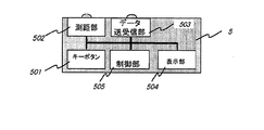
図4は、リモコン5の構成をより詳細に示すブロック図である。リモコン5は、キーボタン501、測距部502、データ送受信部503、表示部504、制御部505を備える。ユーザはキーボタン501を押して、所望の動作の実行を指示することができる。
FIG. 4 is a block diagram showing the configuration of the
測距部502は、カメラ等に使用されるいわゆる反射型の測距部であり、測距対象に対し赤外線を放射し、その反射を利用して距離を測定するものである。キーボタン501が押されると、測距部502がTV装置1とリモコン5との距離を測定する。
The
データ送受信部503は、キーコード及び距離データをTV装置1内のリモコン制御部140へ送信する。また、データ送受信部503は、TV装置1からresponse等を受信する。
The data transmission /
表示部504は、キーボタン操作がTV装置1に受信されなかった場合のエラー表示等を行う。
The
制御部505は、押されたキーボタン501の検出、その検出されたキーボタン501に基づくキーコードのエンコード、該キーコードのTV装置1への送信、response等の受信を制御する。また制御部505は、測距部502の距離測定、得られた距離データの送信を制御する。
The
図5は、プリンタ3の構成をより詳細に示すブロック図である。プリンタ3は、1394I/F部301、1394Asynchronous plugバッファ部302、configuration ROM304、Flash ROM305、プリンタ制御部306、プリンタ機構部307を備える。これらの要素は内部バス1301で接続されている。
FIG. 5 is a block diagram showing the configuration of the
1394I/F部301は、上述した1394I/F部120と同様のものであり、ネットワーク11とプリンタ3内のデータの送受信を制御、管理する。
The 1394 I /
1394Asynchronous plugバッファ部302は、上述した1394Asynchronous plugバッファ部122と同様のものであり、印刷データ等のasynchronousデータの一時格納場所として使用される。
The 1394 Asynchronous
configuration ROM304は、上述したconfiguration ROM123と同様のものであり、その中にはプリンタ3のメーカ名、機器名、製造年月日、ソフトウェアのバージョン、といった機器の固有情報が格納されている。
The
Flash ROM305は、不揮発性の書き換え可能なメモリである。プリンタ制御部306は内部バス1301を通じてFlash ROM305を書き換えることができ、また、他の機器もネットワーク11を通じてFlash ROM305を書き換えることができる。該Flash ROM305には、プリンタ制御部306にて実行されるプログラム、制御コマンド、フォントデータ等が格納されている。
The
プリンタ制御部306は、ネットワーク11、1394I/F部301、1394plugバッファ部302を通じて受け取ったプリンタ制御情報と印刷データに基づき、プリンタ機構部307を制御して印刷を実行させる。
The
プリンタ機構部307は、具体的には図示しないが、プリンタ機構部、印字ヘッド部、該機構及び印字ヘッドの制御部からなり、プリンタ制御部306により制御され、印刷を実行する。
Although not specifically illustrated, the
次に、デジタルTV放送のTS信号について説明する。図6には、放送電波として送出されるTS信号の生成のための生成装置を示す。あるチャネルの信号生成部7には、映像信号s1701、音声信号s1702、付加データs1703が入力される。これらデータは、それぞれビデオエンコーダ701、オーディオエンコーダ702、データエンコーダ730によってエンコードされ、ヘッダが付加されパケット化され、ビデオPES(Packetized Elementary Stream)信号s1704、音声PES信号s1705、データPES信号s1706となる。
Next, a TS signal for digital TV broadcasting will be described. FIG. 6 shows a generation device for generating a TS signal transmitted as a broadcast radio wave. A video signal s1701, audio signal s1702, and additional data s1703 are input to the
その後、TSパケット生成器704が映像、音声、付加データのPES信号s1704〜s1706をまとめて(多重して)一つのチャネルのTS信号s1708(TS1)を生成する。
Thereafter, the
他のチャネル751、752でも同様にして、映像、音声、付加データがまとめられ(多重され)、TS信号s1709(TS2)、s1710(TS3)が生成される。チャネルの数は、1つであってもよく、もっと多い数であってもよい。
Similarly, video, audio, and additional data are collected (multiplexed) in the
3つのTS信号s1708、s1709、s1710は、TS多重化装置753により再度まとめられ(多重され)、TS信号(TS4)s1711が生成される。
The three TS signals s1708, s1709, and s1710 are recombined (multiplexed) by the
また、TS信号には、パケット化、多重化に際し、再生の際の識別子として、PID(Program ID)、PMT(Program Map Table)、table_ID、tag_value等を含むヘッダが付加される。 In addition, a header including PID (Program ID), PMT (Program Map Table), table_ID, tag_value, etc. is added to the TS signal as an identifier at the time of packetization and multiplexing.
なお、上記エンコード法、パケット化法、多重化法に関しては、IEC 13818-1、IEC 13818-2、IEC 13818-3で規定されているものが一般的であるが、その詳細は省略する。 The encoding method, packetizing method, and multiplexing method are generally defined in IEC 13818-1, IEC 13818-2, and IEC 13818-3, but details thereof are omitted.
1つになったTS信号s1711(TS4)は、変調器754で変調された後、アンテナ755より送出される。
The combined TS signal s1711 (TS4) is modulated by the
図7には、TS信号s1711(TS4)より、TS信号s1708(TS1)の付加データs1703を再生(抽出)する過程を模式的に表わす。多重化されたTS4より、まずTS1のみを分離する。これには、video部、audio部、data部の3つが含まれるので、その中からdata部のみを収集し、ヘッダ部を削除して、元のdata(付加データ)を生成する。これらの分離、収集には、PID、PMT、table_ID、tag_value等のヘッダの識別子が使用される。 FIG. 7 schematically shows a process of reproducing (extracting) the additional data s1703 of the TS signal s1708 (TS1) from the TS signal s1711 (TS4). First, only TS1 is separated from the multiplexed TS4. This includes three parts, a video part, an audio part, and a data part, so that only the data part is collected from among them, the header part is deleted, and the original data (additional data) is generated. For the separation and collection, header identifiers such as PID, PMT, table_ID, and tag_value are used.
図8は、付加データのデータ構造について示す。付加データは、ヘッダ(Header)部とデータ(Data)部とに分かれており、ヘッダ部の内容をTVシステム制御部150が解析して、データ部の処理を行う。図8には、ヘッダ部の構成の一例が示されている。ヘッダ部は、target情報、action情報、data情報、CRC dataを含んでいる。
FIG. 8 shows the data structure of the additional data. The additional data is divided into a header section and a data section, and the TV
target情報は、後述するactionの対象となる電子機器(target機器)を特定するための情報を含む。target情報は、target機器を特定する情報であれば、どのような情報であってもよい。例えば、上述のconfiguration ROMに格納されている機器固有の情報(メー力名、機器名、製造番号、製造年月日、ソフトウェアのバージョン等)と比較できる情報であってもよい。 The target information includes information for specifying an electronic device (target device) that is a target of an action described later. The target information may be any information as long as the information specifies the target device. For example, it may be information that can be compared with device-specific information stored in the above-described configuration ROM (such as mail name, device name, serial number, manufacturing date, software version, etc.).
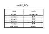
action情報は、図9に示すように、target機器に対して行う処理(動作)を定義する部分である。例えば、データの書き換え、CMデータを用いた宣伝、表示、印刷、といったactionがある。 The action information is a part that defines a process (operation) to be performed on the target device, as shown in FIG. For example, there are actions such as data rewriting, advertisement using CM data, display, and printing.
data情報は、図10に示すように、データ部に格納されたデータの種類―例えば、プログラムデータなのか、印刷データなのか―を表すアプリケーション情報を含む。 As shown in FIG. 10, the data information includes application information indicating the type of data stored in the data part—for example, program data or print data.
(第1の動作例)
次に、図11のフローチャートを参考して、図1に示したネットワークシステムにおける処理動作例について説明する。本例では、TV装置1(A社製品)、VTR2(B社製品)、プリンタ3(C社製品であり、機器名c777、製造年月98年3月、ソフトウェアバージョンc100である。なお、プリンタ3の制御ソフトウェアは、Flash ROM305に格納されている)がネットワーク11に接続されているものとする。
(First operation example)
Next, a processing operation example in the network system shown in FIG. 1 will be described with reference to the flowchart of FIG. In this example, TV apparatus 1 (A company product), VTR 2 (B company product), printer 3 (C company product, device name c777, manufacturing date March 1998, software version c100.
また、本例における放送信号は、図6で説明したように、TS1(TS信号s1708)、TS2(TS信号s1709)、TS3(TS信号s1710)の3つのTS信号が多重化されたTS4(TS信号s1711)となっており、このうちTS1にC社のCM放送が含まれており、そのCM放送に付加データが存在するものとする。 In addition, as described with reference to FIG. 6, the broadcast signal in this example is TS4 (TS signal TS1 (TS signal s1708), TS2 (TS signal s1709), TS3 (TS signal s1710)), which is multiplexed. Signal s1711) of which CM1's CM broadcast is included in TS1, and additional data exists in the CM broadcast.
具体的には、C杜のCM放送データに、機器名c777、製造年月98年1月〜6月、ソフトウェアバージョンc100を有するC社製プリンタを対象として、そのバージョンc100の制御ソフトウェアをバージョンアップデータc101に書き換えるような付加データが含まれているとする。図12は、その付加データのデータ構造を示す。同図に示すように、ヘッダ部の各情報には付加データの内容を示す値が格納されており、データ部には書き換えソフトウェアデータ(バージョンアップデータc101)が格納されている。 Specifically, version C100 of the control software for version C100 is targeted for C 杜 CM broadcast data for a printer manufactured by company C having device name c777 and date of manufacture January-June 1998, software version c100. Assume that additional data that can be rewritten to c101 is included. FIG. 12 shows the data structure of the additional data. As shown in the figure, each piece of information in the header portion stores a value indicating the content of the additional data, and the data portion stores rewrite software data (version upgrade data c101).
いま、VTR2とプリンタ3の電源は既にONとなっており、使用可能であるとする。これらは、以前にもTV装置1に接続されて使用され、TV装置1に認識されたことがあるものとする。
Now, it is assumed that the power sources of the
また、TV装置1とDVDプレーヤ4の電源はOFFになっているものとする。ただし、DVDプレーヤ4は、以前にもTV装置1に接続されて使用された(ONになっていた)ことがあり、TV装置1に認識されたことがあるものとする。
In addition, it is assumed that the
ここで、TV装置1の電源スイッチをONにすると(st601.01)、バスリセットが発生し、IEEE1394I/Fは初期化され、接続情報が再構築されて、接続機器の再認識が行われる。したがって、電源がONで使用可能なVTR2とプリンタ3は、1394I/F部120によって認識され、TVシステム制御部150により認識される(st601.02)。
Here, when the power switch of the
次に、TVシステム制御部150は、1394plugバッファ部122、1394I/F部120を制御し、ネットワーク11に接続されているVTR2及びプリンタ3との間で、TV装置1がconsumer、VTR2及びプリンタ3がproducerとなるように、asynchronous connectionを形成する(st601.03)。
Next, the TV
そして、TVシステム制御部150は、各機器に対して機器固有情報の転送要求を出し(st601.04)、該情報を受信すると、接続機器情報格納部124へ格納する(st601.05)。また、TVシステム制御部150は、TV装置1自身の機器固有情報を、内部バス1101を通じて接続機器情報格納部124へ格納する。
Then, the TV
この際、新たに受信した機器固有情報が以前のバスリセット時に受信した機器固有情報と同じ値であれば、TVシステム制御部150は、以前の値をそのまま残し、異なるところがあれば、その部分を書き直す。また、バスリセット時に、以前受信した機器が認識されなかった場合、TVシステム制御部150は、該機器の固有情報の使用可能情報のみを使用不可とし、それ以外の部分はそのまま残す。本例では、VTR2とプリンタ3の機器情報はそのままであり、DVDプレーヤ4に関する機器情報のうち使用可能情報が使用不可となる。
At this time, if the newly received device specific information is the same value as the device specific information received at the time of the previous bus reset, the TV
上記処理動作(st601.02)の一方で、電源ON後、TV装置1は、アンテナ101により、図6で説明したように送出された放送信号(電波)を受信する。受信された放送信号は、チューナ部102において、同調、増幅、復調され、図7に示したような多重化されたTS信号(TS4)となる(st601.11)。
In the processing operation (st601.02), after the power is turned on, the
ここで、TS信号(TS1)の放送でC杜のCMが始まったとする。この場合、Demux部103が、図7で説明したように、まずTS1を分離し、次にこのTS1を、Video部、audio部、Data部(付加データ)に分離する(st601.12、st601.13)。なお、付加データがない場合は、未処理で終了する(st601.12、st601.51)。
Here, it is assumed that CM of C 杜 starts with broadcasting of the TS signal (TS1). In this case, as described with reference to FIG. 7, the
その後、Video部のデータとaudio部のデータとは、スイッチ部104を通じてTSデコード部105へ送られて、デコードされる。
Thereafter, the data in the video part and the data in the audio part are sent to the
一方、分離された付加データは、データバッファ部106へ送られる。データバッファ部106に付加データが入力されると、TVシステム制御部150は該データをデコードし、ヘッダ部を解析する(st601.14)。TVシステム制御部150は、その付加データが接続機器の対応actionかどうかをヘッダ部内データの整合性によって判別する(st601.15)。なお、接続機器の対応actionでない場合、例えば、EPGデータである、CAデータであるような場合、或いは、解析できない場合は、それに対応する別処理へ移る(st601.52)。
On the other hand, the separated additional data is sent to the
接続機器の対応actionの場合、ヘッダ部内をさらに解析し、該付加データが、C社製品で、機器名c777、製造番号c123、ソフトウェアバージョンc100を対象にしたものであることを判別し、接続機器情報格納部124に該情報と一致する機器固有情報があるかどうかを検索する(st601.16)。なお、存在しない場合は、未処理として、該付加データは破棄され、終了する。(st601.53) In the case of the action for the connected device, the header portion is further analyzed, and it is determined that the additional data is a product of Company C, the device name c777, the serial number c123, and the software version c100. It is searched whether there is device-specific information that matches the information in the information storage unit 124 (st601.16). If it does not exist, the additional data is discarded and the processing ends. (St601.53)
接続機器情報格納部124に一致する機器固有情報がある場合、その使用可能情報を参照することで当該機器が使用可能であるかどうか調べる(st601.17)。使用不可能になっている場合は、その付加データを付加データ格納部128へ保存し、この情報は表示器131に表示される。例えば、『あなたのご使用になっているC杜のプリンタc777に関する情報が受信されました。プリンタの電源をONにして下さい。』のごとくである。
If there is device-specific information that matches the connected device
なお、保存された付加データは、機器が使用可能になった際に、その内容が実行される(st601.54)。また、保存された付加データは、TVシステム制御部150によって管理され、ある一定時間以上たっても実行されない場合は破棄(消去)されるようになっている。
The stored additional data is executed when the device becomes usable (st601.54). The stored additional data is managed by the TV
本例では、プリンタ3(C社製品であり、機器名c777、製造年月98年3月、ソフトウェアバージョンc100)があり、電源ONで使用可能であるので、先へ進み、付加データのヘッダ部のaction情報から、action動作がソフトウェアの書き換えであることを判別する(st601.18)。なお、そうでない場合は、ヘッダ部のaction情報に従った別処理を行う(st601.55)。 In this example, there is a printer 3 (C company product, device name c777, manufacturing date March 1998, software version c100), which can be used when the power is turned on. From the action information, it is determined that the action operation is software rewriting (st601.18). Otherwise, another process is performed according to the action information in the header part (st601.55).
次に、TVシステム制御部150は、付加データがソフトウェアデータの書き換え処理に関係することを判別したので、TV装置1がproducer、プリンタ3がconsumerとなるように、asynchronous connectionを形成する(st601.19)。
Next, since the TV
そして、TVシステム制御部150は、ネットワーク11を通じて、プリンタ3の1394plugバッファ部302内のsegment buffer内に、付加データのデータ部で与えられたデータを書き込む(st601.20)。
Then, the TV
データ転送が終了すると、TVシステム制御部150は、プリンタ3との間に形成したasynchronous connectionを切断して終了する(st601.21)。
When the data transfer ends, the TV
一方、プリンタ3のプリンタ制御部306は、1394plugバッファ部302内のsegment buffer内に受信したデータを解析し、自分のプリンタの制御ソフトウェアのバージョンアップデータであることを判別し、該データをFlash ROM305内のプログラム部へ転送する(st601.22)。
On the other hand, the
以上述べたように、本動作例によれば、放送信号に含まれる付加データを利用して、ホームネットワーク11に接続されたプリンタ3の制御ソフトウェアが自動的にバージョンアップされる。
As described above, according to this operation example, the control software of the
(第2の動作例)
次に、図13のフローチャートを参考して、図1に示したネットワークシステムにおける処理動作例について説明する。本例では、TV装置1(A社製品)、VTR2(B社製品であり、カテゴリVHS Video、機器名b123、製造年月92年7月)、プリンタ3(C社製品)がネットワーク11に接続されているものとする。
(Second operation example)
Next, a processing operation example in the network system shown in FIG. 1 will be described with reference to the flowchart of FIG. In this example, a TV device 1 (A company product), VTR 2 (B company product, category VHS Video, device name b123, date of manufacture July 1992), and printer 3 (C company product) are connected to the
また、本例における放送信号は、上述した動作例1と同様に、TS1(TS信号s1708)にCM放送が含まれており、そのCM放送に付加データが存在するものとする。 In the broadcast signal in this example, it is assumed that the CM broadcast is included in TS1 (TS signal s1708), and additional data exists in the CM broadcast, as in the first operation example.
具体的には、S杜のCM放送データに、カテゴリVHS Video、製造年月93年1月以前、或いは、S社製品s123類似品を対象として、S杜新製品の買い替えキャンペーンの広告データが含まれており、プリンタがあれば、印刷するように設定されているとする。図14には、その付加データのデータ構造を示す。同図に示すように、ヘッダ部には付加データの内容を示す値が格納され、データ部には印刷データが格納されている。 Specifically, S 杜 CM broadcast data includes advertisement data for the campaign for replacement of S 杜 new products targeting category VHS Video, date of manufacture before January 1993, or S product s123 similar products. If there is a printer, it is set to print. FIG. 14 shows the data structure of the additional data. As shown in the figure, a value indicating the content of the additional data is stored in the header portion, and print data is stored in the data portion.
TV装置1の電源スイッチをONにすると(st602.01)、上述した動作例1と同様、バスリセットが発生し、IEEE1394I/Fは初期化され、接続情報が再構築されて、TVシステム制御部150がネットワーク11に接続された電子機器を認識する。(st602.02)
When the power switch of the
次に、TVシステム制御部150は、1394plugバッファ部122、1394I/F部120を制御し、ネットワーク11に接続されているVTR2及びプリンタ3との間で、TV装置1がconsumer、VTR2及びプリンタ3がproducerとなるように、asynchronous connectionを形成する(st602.03)。
Next, the TV
そして、TVシステム制御部150は、各機器に対して機器固有情報の転送要求を出し(st602.04)、該情報を受信すると、接続機器情報格納部124へ格納する(st602.05)。VTR2について説明すれば、B社製品で、カテゴリVHS Video、機器名b123、製造年月92年7月であるといった情報が格納される。また、TV装置1自身の機器固有情報が、内部バス1101を通じて機器情報格納部124へ格納される。
Then, the TV
上記処理動作(st602.02)の一方で、電源ON後、TV装置1は、アンテナ101により、図6で説明したように送出された放送信号を受信する。受信された放送信号は、チューナ部102において、同調、増幅、復調され、図7に示したような多重化されたTS信号(TS4)となる(st602.11)。
On the other hand, after the power is turned on in the above processing operation (st602.02), the
ここで、TS信号(TS1)の放送でS杜のCMが始まったとする。この場合、Demux部103が、図7で説明したように、まずTS1を分離し、次にこのTS1を、Video部、audio部、Data部(付加データ)に分離する(st602.12、st602.13)。なお、付加データがない場合は、未処理で終了する(st602.12、st602.51)。
Here, it is assumed that the CM of S 杜 starts with the broadcasting of the TS signal (TS1). In this case, as described with reference to FIG. 7, the
その後、Video部のデータとaudio部のデータとは、スイッチ部104を通じてTSデコード部105へ送られて、デコードされる。
Thereafter, the data in the video part and the data in the audio part are sent to the
一方、分離された付加データは、データバッファ部106へ送られる。データバッファ部106に付加データが入力されると、TVシステム制御部150は該データをデコードし、ヘッダ部を解析する(st602.14)。TVシステム制御部150は、その付加データが接続機器の対応actionかどうかをヘッダ部内データの整合性によって判別する(st602.15)。なお、接続機器の対応actionでない場合、例えば、EPGデータである、CAデータであるような場合、或いは、解析できない場合は、それに対応する別処理へ移る(st602.52)。
On the other hand, the separated additional data is sent to the
接続機器の対応actionの場合、ヘッダ部内をさらに解析し、該付加データが、カテゴリVHS Video、製造年月93年1月以前を対象にしたものであることを判別し、接続機器情報格納部124に該情報と一致する機器固有情報があるかどうかを検索する(st602.16)。なお、存在しない場合は、未処理として、該付加データは破棄され、終了する。(st602.53)
In the case of the action corresponding to the connected device, the inside of the header portion is further analyzed, it is determined that the additional data is for the category VHS Video, the date of manufacture before January 1993, and the connected
本例では、VTR2が対象となる(機器情報格納部124内に、一致する機器固有情報がある)ので(st602.17)、先へ進み、付加データのヘッダ部のaction情報から、action動作がデータ印刷であることを判別する(st602.18)。なお、そうでない場合は、ヘッダ部のaction情報に従った別処理を行う(st602.55)。
In this example, since VTR2 is the target (the device
次に、TVシステム制御部150は、付加データが印刷処理に関係することを判別したので、ネットワーク上にプリンタがあるかどうかを検索する(st602.19)。本例の場合、ネットワーク上にプリンタ3がある。よって、TVシステム制御部150は、プリンタ3に印刷を実行させるために、TV装置1がproducer、プリンタ3がconsumerとなるように、asynchronous connectionを形成する(st602.20)。
Next, since the TV
そして、TVシステム制御部150は、印刷制御部125を使用し、データバッファ部106内のデータをIEEE1394ネットワークを通じてプリンタ3に転送する。このデータは、プリンタ3の1394plugバッファ部302内のsegment buffer内に書き込まれる(st602.21)。
Then, the TV
データ転送が終了すると、TVシステム制御部150は、プリンタ3との間に形成したasynchronous connectionを切断して終了する(st602.22)。
When the data transfer ends, the TV
一方、プリンタ3のプリンタ制御部306は、1394plugバッファ部302内のsegment buffer内に受信したデータを解析し、自分のプリンタの印刷データであることを判別し、該データをプリンタ機構部307へ転送し、印刷を実行する(st602.23)。
On the other hand, the
以上述べたように、本動作例によれば、付加データとVTR2の機器固有情報とを照合した結果に応じて、別の機器であるプリンタ3に印刷処理を実行させることができる。
As described above, according to this operation example, it is possible to cause the
なお、上記実施の形態においては、各機器を接続するためのネットワークとしてIEEE1394を使用したが、12Cバス、イーサネット(R)、USB等を使用し、接続機器の認識手段を設けてもかまわない。ネットワークは有線でも無線でもよい。電送媒体も、電気信号に限らず、光ファイバケーブル、赤外線、電波等であってもよい。また、1種類とせずに、複数のネットワークを結合することも可能である。すなわち、ネットワークは、別々の筐体を有する複数の電子機器を相互に接続できる手段であればよい。 In the above embodiment, IEEE1394 is used as a network for connecting each device. However, a 12C bus, Ethernet (R), USB, or the like may be used, and connected device recognition means may be provided. The network may be wired or wireless. The transmission medium is not limited to an electrical signal, and may be an optical fiber cable, infrared rays, radio waves, or the like. It is also possible to combine a plurality of networks without using one type. That is, the network may be any means that can connect a plurality of electronic devices having different housings to each other.
また、本実施の形態においては、TV装置の電源スイッチONによって、IEEE1394I/Fにバスリセットをかけ接続機器の認識を行ったが、これは、他の機器の電源ON/OFF、コネクタの挿抜等、IEEE1394I/Fにバスリセットをかけることができればどのようなものでもよい。 In this embodiment, the IEEE1394 I / F is reset by the power switch ON of the TV device and the connected device is recognized. However, this includes power ON / OFF of other devices, connector insertion / extraction, etc. Any device can be used as long as a bus reset can be applied to the IEEE1394 I / F.
また、本実施の形態においては、TV装置1、VTR2、プリンタ3、DVDプレーヤ4が接続されたネットワークシステムを説明したが、他の電子機器、例えば、TVチューナ、FMチューナ、オーディオカセットレコーダ、アンプ等のAV機器や、PC(パーソナルコンピュータ)、スキャナ、FAX、電話、モデム、ディスプレイモニタ、プリンタ、複写機等のOA機器や、冷蔵庫、洗濯機、アイロン等の家庭電化製品や、ドアホン、浴室管理システム、防犯システム等の家庭内ネットワークシステムまで応用することができる。
In the present embodiment, the network system to which the
また、本実施の形態におけるTV装置1は、チューナ部、Demux部、TVシステム制御部等の多くの機能を有しているが、これら各機能は、IEEE1394I/Fによって接続された機器、例えばプリンタ内に存在し、統括的に制御するようにしてもかまわない。
The
また、本実施の形態では、電子機器に実行させる「所定の処理」の一例として、データの書き換え(ソフトウェアのバージョンアップ)処理と印刷処理を示した。しかし、上述したように、本発明は種々の電子機器に適用可能であるため、対象とする電子機器の種類や機能に応じて、様々な処理を実行させることができる。例えば、「所定の処理」として、TV装置やPCに対する表示処理(バージョンアップを促す表示、バージョンアップ作業を行うことを告知する表示、接続された電子機器が広告対象となることを示す表示等)や、AV機器に対する音声出力処理を実行させることもできる。また、TV装置1も電子機器の一つなので、TV装置1が付加データに基づきTV装置1自身に所定の処理を実行させてもよい。
In this embodiment, data rewrite (software version upgrade) processing and printing processing are shown as examples of “predetermined processing” to be executed by the electronic device. However, as described above, since the present invention can be applied to various electronic devices, various processes can be executed according to the type and function of the target electronic device. For example, as “predetermined processing”, display processing for a TV device or a PC (display for prompting upgrade, display for notifying that upgrade work is performed, display indicating that a connected electronic device is an advertisement target, etc.) Or, audio output processing for an AV device can be executed. Since the
なお、本実施の形態では、付加データに基づき電子機器を制御する処理回路がTV装置1の筐体内部に設けられている。しかし、放送信号を受信する手段と、上記処理回路とを同一の筐体に設ける必要はなく、別の筐体として、すなわち処理回路を独立の装置もしくはTV装置1以外の電子機器の内部に設けてもよい。
In the present embodiment, a processing circuit that controls the electronic device based on the additional data is provided inside the casing of the
(その他の実施の形態)
上述した実施の形態の機能を実現するべく各種のデバイスを動作させるように、該各種デバイスと接続された装置或いはシステム内のコンピュータに対し、上記実施の形態の機能を実現するためのソフトウェアのプログラムコードを供給し、そのシステム或いは装置のコンピュータ(CPU或いはMPU)に格納されたプログラムに従って上記各種デバイスを動作させることによって実施したものも、本発明の範疇に含まれる。
(Other embodiments)
Software program for realizing the functions of the above-described embodiment for an apparatus or a computer in the system connected to the various devices so as to operate the various devices to realize the functions of the above-described embodiments. What was implemented by supplying the code and operating the various devices in accordance with a program stored in a computer (CPU or MPU) of the system or apparatus is also included in the scope of the present invention.
また、この場合、上記ソフトウェアのプログラムコード自体が上述した実施の形態の機能を実現することになり、そのプログラムコード自体は本発明を構成する。そのプログラムコードの伝送媒体としては,プログラム情報を搬送波として伝搬させて供給するためのコンピュータネットワーク(LAN、インターネット等のWAN、無線通信ネットワーク等)システムにおける通信媒体(光ファイバ等の有線回線や無線回線等)を用いることができる。 In this case, the program code of the software itself realizes the functions of the above-described embodiments, and the program code itself constitutes the present invention. As a transmission medium of the program code, a communication medium (wired line or wireless line such as an optical fiber) in a computer network (LAN, WAN such as the Internet, wireless communication network, etc.) system for propagating and supplying program information as a carrier wave Etc.) can be used.
さらに、上記プログラムコードをコンピュータに供給するための手段、例えばかかるプログラムコードを格納した記録媒体は本発明を構成する。かかるプログラムコードを記憶する記録媒体としては、例えばフレキシブルディスク、ハードディスク、光ディスク、光磁気ディスク、CD−ROM、磁気テープ、不揮発性のメモリカード、ROM等を用いることができる。 Further, means for supplying the program code to the computer, for example, a recording medium storing the program code constitutes the present invention. As a recording medium for storing the program code, for example, a flexible disk, a hard disk, an optical disk, a magneto-optical disk, a CD-ROM, a magnetic tape, a nonvolatile memory card, a ROM, or the like can be used.
また、コンピュータが供給されたプログラムコードを実行することにより、上述の実施の形態の機能が実現されるだけでなく、そのプログラムコードがコンピュータにおいて稼働しているOS(オペレーティングシステム)或いは他のアプリケーションソフト等と共同して上述の実施の形態の機能が実現される場合にもかかるプログラムコードは本発明の実施の形態に含まれることはいうまでもない。 Further, by executing the program code supplied by the computer, not only the functions of the above-described embodiments are realized, but also the OS (operating system) or other application software in which the program code is running on the computer. Needless to say, the program code is also included in the embodiment of the present invention even when the functions of the above-described embodiment are realized in cooperation with the above.
さらに、供給されたプログラムコードがコンピュータの機能拡張ボードやコンピュータに接続された機能拡張ユニットに備わるメモリに格納された後、そのプログラムコードの指示に基づいてその機能拡張ボードや機能拡張ユニットに備わるCPU等が実際の処理の一部又は全部を行い、その処理によって上述した実施の形態の機能が実現される場合にも本発明に含まれることはいうまでもない。 Further, after the supplied program code is stored in the memory provided in the function expansion board of the computer or the function expansion unit connected to the computer, the CPU provided in the function expansion board or function expansion unit based on the instruction of the program code Needless to say, the present invention also includes the case where the functions of the above-described embodiment are realized by performing part or all of the actual processing.
なお、上記実施の形態において示した各部の形状及び構造は、何れも本発明を実施するにあたっての具体化のほんの一例を示したものに過ぎず、これらによって本発明の技術的範囲が限定的に解釈されてはならないものである。すなわち、本発明はその精神、又はその主要な特徴から逸脱することなく、様々な形で実施することができる。 It should be noted that the shapes and structures of the respective parts shown in the above embodiments are merely examples of implementation in carrying out the present invention, and these limit the technical scope of the present invention. It should not be interpreted. That is, the present invention can be implemented in various forms without departing from the spirit or main features thereof.
1 TV装置
2 VTR
3 プリンタ
4 DVDプレーヤ
5 リモコン
101 アンテナ
102 チューナ部
103 Demultiplex部(Demux部)
104 スイッチ部
105 TSデコード部
106 データバッファ部
107 TV受信制御部
120 1394I/F部
121 1394Isochronousバッファ部
122 1394Asynchronous plugバッファ部
123 configuration ROM部
124 接続機器情報格納部
125 印刷制御部
126 静止画バッファ部
127 DVCRデコード部
128 付加データ格納部
130 表示合成制御部
131 表示器
132 音声合成制御部
133 音声出力部
140 リモコン制御部
150 TVシステム制御部
1
3 Printer 4
Claims (5)
電子機器を識別するための識別データ、及び、電子機器を制御するための制御データを含む放送信号を受信する受信手段と、
前記テレビジョン装置に接続されている電子機器の固有情報を格納する第1記憶部と、
前記受信手段が受信した前記制御データを格納するための第2記憶部と、
前記受信手段が受信した前記識別データと、前記第1記憶部に格納されている前記固有情報とを比較する比較手段と、
前記比較手段による比較の結果、前記受信手段が受信した前記識別データと、前記第1記憶部に格納されている前記固有情報が一致する場合、接続されている前記電子機器が使用可能かどうかを示す使用可能情報を前記電子機器から取得する取得手段と、
前記電子機器に前記制御データに基づいて、前記電子機器が保有しているソフトウェアのバージョンアップ処理を実行させる制御手段と、を有し、
前記接続されている前記電子機器が使用可能であることを、前記取得手段が取得した前記使用可能情報が示す場合には、前記制御手段は、接続されている前記電子機器に前記受信手段が受信した前記制御データに基づいて、前記電子機器が保有しているソフトウェアのバージョンアップ処理を実行させ、
前記接続されている前記電子機器が使用不可能であることを、前記取得手段が取得した使用可能情報が示す場合には、前記制御手段は前記制御データを前記第2記憶部に格納し、前記電子機器が使用可能になったことに応じて、前記第2記憶部に格納された前記制御データに基づいて、前記電子機器が保有しているソフトウェアのバージョンアップ処理を前記電子機器に実行させることを特徴とするテレビジョン装置。 A television device to which an electronic device can be connected,
Receiving means for receiving broadcast data including identification data for identifying an electronic device and control data for controlling the electronic device;
A first storage unit storing unique information of an electronic device connected to the television device;
A second storage unit for storing the control data received by the receiving means;
Comparing means for comparing the identification data received by the receiving means with the unique information stored in the first storage unit;
As a result of the comparison by the comparison means, if the identification data received by the reception means matches the unique information stored in the first storage unit, whether or not the connected electronic device is usable Acquisition means for acquiring usable information to be shown from the electronic device;
Wherein based on the control data to the electronic device, and a control means for executing the upgrade process of the software the electronic device is held,
When the availability information acquired by the acquisition unit indicates that the connected electronic device is usable, the control unit receives the reception unit from the connected electronic device. Based on the control data, the software upgrade process of the electronic device is executed,
When the use information acquired by the acquisition unit indicates that the connected electronic device is unusable, the control unit stores the control data in the second storage unit, and In response to the availability of the electronic device, causing the electronic device to execute a software upgrade process held by the electronic device based on the control data stored in the second storage unit. A television apparatus characterized by the above.
電子機器を識別するための識別データ、及び、電子機器を制御するための制御データを含む放送信号を受信する受信ステップと、
前記受信ステップで受信した前記識別データと、第1記憶部に格納されている前記テレビジョン装置に接続されている電子機器の固有情報とを比較する比較ステップと、
前記比較ステップによる比較の結果、前記受信ステップで受信した前記識別データと、前記第1記憶部に格納されている前記固有情報が一致する場合、接続されている前記電子機器が使用可能かどうかを示す使用可能情報を前記電子機器から取得する取得ステップと、
前記電子機器に前記制御データに基づいて、前記電子機器が保有しているソフトウェアのバージョンアップ処理を実行させる制御ステップと、を有し、
前記接続されている前記電子機器が使用可能であることを、前記取得ステップで取得した前記使用可能情報が示す場合には、前記制御ステップでは、接続されている前記電子機器に受信ステップで受信した前記制御データに基づいて、前記電子機器が保有しているソフトウェアのバージョンアップ処理を実行させ、
前記接続されている前記電子機器が使用不可能であることを、前記取得ステップで取得した使用可能情報が示す場合には、前記制御ステップでは、前記制御データを第2記憶部に格納し、前記電子機器が使用可能になったことに応じて、前記第2記憶部に格納された前記制御データに基づいて、前記電子機器が保有しているソフトウェアのバージョンアップ処理を前記電子機器に実行させることを特徴とするテレビジョン装置の制御方法。 A control method of a television device to which an electronic device can be connected,
A reception step of receiving broadcast data including identification data for identifying the electronic device and control data for controlling the electronic device;
A comparison step of comparing the identification data received in the reception step with unique information of an electronic device connected to the television set stored in the first storage unit;
As a result of the comparison in the comparison step, if the identification data received in the reception step matches the unique information stored in the first storage unit, whether or not the connected electronic device is usable Obtaining the usable information to be obtained from the electronic device;
Wherein based on the control data to the electronic device, and a control step of executing the upgrade process of the software the electronic device is held,
When the usable information obtained in the obtaining step indicates that the connected electronic device is usable, the control step receives the connected electronic device in the receiving step. Based on the control data, to execute a software upgrade process held by the electronic device ,
When the availability information acquired in the acquisition step indicates that the connected electronic device is unusable, the control step stores the control data in a second storage unit, and In response to the availability of the electronic device, causing the electronic device to execute a software upgrade process held by the electronic device based on the control data stored in the second storage unit. A control method for a television device.
Priority Applications (4)
| Application Number | Priority Date | Filing Date | Title |
|---|---|---|---|
| JP2004131410A JP4693363B2 (en) | 2003-05-28 | 2004-04-27 | Television apparatus and control method thereof |
| CNB2004100432552A CN100355236C (en) | 2003-05-28 | 2004-05-14 | Network system and electronic device |
| US10/845,176 US7610609B2 (en) | 2003-05-28 | 2004-05-14 | Network system and electronic device |
| KR1020040037752A KR20040103340A (en) | 2003-05-28 | 2004-05-27 | Network system and electronic device |
Applications Claiming Priority (3)
| Application Number | Priority Date | Filing Date | Title |
|---|---|---|---|
| JP2003151174 | 2003-05-28 | ||
| JP2003151174 | 2003-05-28 | ||
| JP2004131410A JP4693363B2 (en) | 2003-05-28 | 2004-04-27 | Television apparatus and control method thereof |
Publications (3)
| Publication Number | Publication Date |
|---|---|
| JP2005012766A JP2005012766A (en) | 2005-01-13 |
| JP2005012766A5 JP2005012766A5 (en) | 2007-05-17 |
| JP4693363B2 true JP4693363B2 (en) | 2011-06-01 |
Family
ID=33455560
Family Applications (1)
| Application Number | Title | Priority Date | Filing Date |
|---|---|---|---|
| JP2004131410A Expired - Fee Related JP4693363B2 (en) | 2003-05-28 | 2004-04-27 | Television apparatus and control method thereof |
Country Status (4)
| Country | Link |
|---|---|
| US (1) | US7610609B2 (en) |
| JP (1) | JP4693363B2 (en) |
| KR (1) | KR20040103340A (en) |
| CN (1) | CN100355236C (en) |
Families Citing this family (8)
| Publication number | Priority date | Publication date | Assignee | Title |
|---|---|---|---|---|
| KR100736032B1 (en) * | 2005-02-02 | 2007-07-06 | 삼성전자주식회사 | Mobile storage, video equipment and channel limiting method for video equipment using mobile storage |
| EP1715603A3 (en) | 2005-04-18 | 2009-11-25 | LG Electronics, Inc. | Apparatus and method for controlling electric appliances using broadcast wave, and apparatus and method for controlling home network |
| JP2007050566A (en) | 2005-08-16 | 2007-03-01 | Canon Inc | Image forming apparatus and its control method |
| KR100781523B1 (en) * | 2006-04-25 | 2007-12-03 | 삼성전자주식회사 | Apparatus and method for structuring IP identification packet and allotting IP |
| KR100791304B1 (en) * | 2006-07-24 | 2008-01-04 | 삼성전자주식회사 | Apparatus, system and method for software upgrading |
| JP4775400B2 (en) * | 2008-04-15 | 2011-09-21 | 船井電機株式会社 | Audiovisual system |
| MX2011012970A (en) * | 2009-06-05 | 2012-02-01 | Sharp Kk | Software updating system, electronic devices, and software updating method. |
| CN102663885B (en) * | 2012-03-23 | 2017-11-07 | 中兴通讯股份有限公司 | A kind of method operated to display device, system and relevant device |
Citations (6)
| Publication number | Priority date | Publication date | Assignee | Title |
|---|---|---|---|---|
| JPH10257451A (en) * | 1997-03-07 | 1998-09-25 | Sony Corp | Data transmitter, receiver, system and method for transmitting data |
| JPH1124899A (en) * | 1997-07-04 | 1999-01-29 | Sony Corp | Electronic instrument and electronic instrument system |
| JPH11237966A (en) * | 1998-02-23 | 1999-08-31 | Seiko Epson Corp | Method and system for printing television broadcast multiplexed data, and recording medium recorded with television broadcast multiplexed data processing program |
| JP2002152650A (en) * | 2000-11-10 | 2002-05-24 | Sharp Corp | Digital broadcast receiving system |
| JP2002196943A (en) * | 2000-12-27 | 2002-07-12 | Victor Co Of Japan Ltd | Digital broadcasting down load system |
| JP2004173128A (en) * | 2002-11-22 | 2004-06-17 | Clarion Co Ltd | Digital broadcasting system, digital broadcasting receiver and digital broadcasting terminal device |
Family Cites Families (20)
| Publication number | Priority date | Publication date | Assignee | Title |
|---|---|---|---|---|
| US4633309A (en) * | 1985-05-06 | 1986-12-30 | Oak Industries Inc. | Cable television master/slave decoder control |
| US4695880A (en) * | 1985-07-30 | 1987-09-22 | Postron Corp. | Electronic information dissemination system |
| US5886732A (en) * | 1995-11-22 | 1999-03-23 | Samsung Information Systems America | Set-top electronics and network interface unit arrangement |
| EP0783229A1 (en) | 1995-12-28 | 1997-07-09 | U.S. Narrow Networks, Inc. | Method and apparatus for providing coupons and information printouts to a consumer |
| TW304251B (en) * | 1996-10-04 | 1997-05-01 | Cheng Shen Co Ltd | Consumer electric apparatus control system |
| JP3870983B2 (en) | 1997-02-17 | 2007-01-24 | ソニー株式会社 | Electronic device control apparatus and method, and electronic device |
| US6263497B1 (en) * | 1997-07-31 | 2001-07-17 | Matsushita Electric Industrial Co., Ltd. | Remote maintenance method and remote maintenance apparatus |
| JP3261399B2 (en) | 1997-07-31 | 2002-02-25 | 松下電器産業株式会社 | Remote maintenance method and remote maintenance device |
| KR100385966B1 (en) | 1998-05-06 | 2003-08-19 | 삼성전자주식회사 | Method and apparatus for granting the right of control command for digital device in home network |
| US6038425A (en) * | 1998-08-03 | 2000-03-14 | Jeffrey; Ross A. | Audio/video signal redistribution system |
| US6282713B1 (en) * | 1998-12-21 | 2001-08-28 | Sony Corporation | Method and apparatus for providing on-demand electronic advertising |
| US6311206B1 (en) * | 1999-01-13 | 2001-10-30 | International Business Machines Corporation | Method and apparatus for providing awareness-triggered push |
| US6588017B1 (en) * | 1999-01-27 | 2003-07-01 | Diva Systems Corporation | Master and slave subscriber stations for digital video and interactive services |
| JP2001134581A (en) * | 1999-11-02 | 2001-05-18 | Nec Corp | Method, device, and receiver for advertisement, and recording medium |
| JP4265053B2 (en) * | 1999-11-04 | 2009-05-20 | ソニー株式会社 | Digital broadcast receiving system, digital broadcast receiving apparatus, receiving apparatus, printing apparatus, and printing method |
| JP2002290853A (en) * | 2001-03-22 | 2002-10-04 | Canon Inc | Receiver, method, and program for television broadcast reception |
| KR100403300B1 (en) | 2001-07-26 | 2003-10-23 | 전자부품연구원 | Equipment for extracting the control signal of entertainment equipment in digital broadcasting signal and extracting method therein |
| JP2003046986A (en) | 2001-08-03 | 2003-02-14 | Matsushita Electric Ind Co Ltd | Receiver |
| JP3863118B2 (en) * | 2002-04-01 | 2006-12-27 | 松下電器産業株式会社 | Receiving device, printing device, and firmware update system |
| JP4401721B2 (en) | 2002-09-26 | 2010-01-20 | キヤノン株式会社 | Video receiver |
-
2004
- 2004-04-27 JP JP2004131410A patent/JP4693363B2/en not_active Expired - Fee Related
- 2004-05-14 CN CNB2004100432552A patent/CN100355236C/en not_active Expired - Fee Related
- 2004-05-14 US US10/845,176 patent/US7610609B2/en not_active Expired - Fee Related
- 2004-05-27 KR KR1020040037752A patent/KR20040103340A/en active Search and Examination
Patent Citations (6)
| Publication number | Priority date | Publication date | Assignee | Title |
|---|---|---|---|---|
| JPH10257451A (en) * | 1997-03-07 | 1998-09-25 | Sony Corp | Data transmitter, receiver, system and method for transmitting data |
| JPH1124899A (en) * | 1997-07-04 | 1999-01-29 | Sony Corp | Electronic instrument and electronic instrument system |
| JPH11237966A (en) * | 1998-02-23 | 1999-08-31 | Seiko Epson Corp | Method and system for printing television broadcast multiplexed data, and recording medium recorded with television broadcast multiplexed data processing program |
| JP2002152650A (en) * | 2000-11-10 | 2002-05-24 | Sharp Corp | Digital broadcast receiving system |
| JP2002196943A (en) * | 2000-12-27 | 2002-07-12 | Victor Co Of Japan Ltd | Digital broadcasting down load system |
| JP2004173128A (en) * | 2002-11-22 | 2004-06-17 | Clarion Co Ltd | Digital broadcasting system, digital broadcasting receiver and digital broadcasting terminal device |
Also Published As
| Publication number | Publication date |
|---|---|
| KR20040103340A (en) | 2004-12-08 |
| JP2005012766A (en) | 2005-01-13 |
| US20040240475A1 (en) | 2004-12-02 |
| US7610609B2 (en) | 2009-10-27 |
| CN1574743A (en) | 2005-02-02 |
| CN100355236C (en) | 2007-12-12 |
Similar Documents
| Publication | Publication Date | Title |
|---|---|---|
| EP0873009B1 (en) | Multimedia system for transferring and receiving program number and methods therefor | |
| JPH11346166A (en) | Portable viewing system | |
| JP5045535B2 (en) | Receiving apparatus and receiving method | |
| JP2000324472A (en) | Method and device for control | |
| JP2007511960A (en) | Interchangeable media input cartridge for home entertainment | |
| CN101483756A (en) | Television system and method convenient for recording and playing programme | |
| JP4693363B2 (en) | Television apparatus and control method thereof | |
| EP2103112B1 (en) | Image signal processing apparatus for detaching a plurality of modules and control method thereof | |
| EP1455533A1 (en) | Information processing apparatus and data transfer method for use in the same | |
| JP4734828B2 (en) | Display device and playback device | |
| JP4016160B2 (en) | Data receiving / recording method and data receiving apparatus | |
| JP2003198999A (en) | Broadcast receiving device with video-recorder control function | |
| EP1359751A2 (en) | Digital broadcast receiving apparatus and control method thereof | |
| JP2006054022A (en) | Device and method for controlling recording | |
| CN101304509A (en) | Recording control apparatus, method for controlling recording control apparatus and recording control system | |
| JP2000333043A (en) | Information processing unit and its method | |
| JP2003319279A (en) | Digital tv broadcasting receiver | |
| JP4016159B2 (en) | Data receiving apparatus and data receiving method | |
| JP2007266815A (en) | Broadcast system and broadcast transmitter and broadcast receiver configuring the same | |
| JP2019024152A (en) | Electronic apparatus and reception method | |
| JP2001101789A (en) | Unit and method for processing information, and recording medium | |
| KR20070036315A (en) | Method for pvr to digital image data of backup | |
| JP2000010906A (en) | Audiovisual equipment and its control method | |
| JP2010041681A (en) | Av equipment | |
| JP2009124281A (en) | Hard disk device |
Legal Events
| Date | Code | Title | Description |
|---|---|---|---|
| A521 | Request for written amendment filed |
Free format text: JAPANESE INTERMEDIATE CODE: A523 Effective date: 20070322 |
|
| A621 | Written request for application examination |
Free format text: JAPANESE INTERMEDIATE CODE: A621 Effective date: 20070322 |
|
| A977 | Report on retrieval |
Free format text: JAPANESE INTERMEDIATE CODE: A971007 Effective date: 20100201 |
|
| A131 | Notification of reasons for refusal |
Free format text: JAPANESE INTERMEDIATE CODE: A131 Effective date: 20100216 |
|
| A521 | Request for written amendment filed |
Free format text: JAPANESE INTERMEDIATE CODE: A523 Effective date: 20100414 |
|
| A02 | Decision of refusal |
Free format text: JAPANESE INTERMEDIATE CODE: A02 Effective date: 20100928 |
|
| A521 | Request for written amendment filed |
Free format text: JAPANESE INTERMEDIATE CODE: A523 Effective date: 20101214 |
|
| A911 | Transfer to examiner for re-examination before appeal (zenchi) |
Free format text: JAPANESE INTERMEDIATE CODE: A911 Effective date: 20101221 |
|
| TRDD | Decision of grant or rejection written | ||
| A01 | Written decision to grant a patent or to grant a registration (utility model) |
Free format text: JAPANESE INTERMEDIATE CODE: A01 Effective date: 20110215 |
|
| A01 | Written decision to grant a patent or to grant a registration (utility model) |
Free format text: JAPANESE INTERMEDIATE CODE: A01 |
|
| A61 | First payment of annual fees (during grant procedure) |
Free format text: JAPANESE INTERMEDIATE CODE: A61 Effective date: 20110222 |
|
| FPAY | Renewal fee payment (event date is renewal date of database) |
Free format text: PAYMENT UNTIL: 20140304 Year of fee payment: 3 |
|
| R150 | Certificate of patent or registration of utility model |
Free format text: JAPANESE INTERMEDIATE CODE: R150 |
|
| LAPS | Cancellation because of no payment of annual fees |