JP4265053B2 - Digital broadcast receiving system, digital broadcast receiving apparatus, receiving apparatus, printing apparatus, and printing method - Google Patents
Digital broadcast receiving system, digital broadcast receiving apparatus, receiving apparatus, printing apparatus, and printing method Download PDFInfo
- Publication number
- JP4265053B2 JP4265053B2 JP31428999A JP31428999A JP4265053B2 JP 4265053 B2 JP4265053 B2 JP 4265053B2 JP 31428999 A JP31428999 A JP 31428999A JP 31428999 A JP31428999 A JP 31428999A JP 4265053 B2 JP4265053 B2 JP 4265053B2
- Authority
- JP
- Japan
- Prior art keywords
- image data
- receiving
- printing
- unit
- signal
- Prior art date
- Legal status (The legal status is an assumption and is not a legal conclusion. Google has not performed a legal analysis and makes no representation as to the accuracy of the status listed.)
- Expired - Fee Related
Links
- 238000000034 method Methods 0.000 title claims description 69
- 238000012545 processing Methods 0.000 claims description 104
- 230000008054 signal transmission Effects 0.000 claims description 103
- 238000006243 chemical reaction Methods 0.000 claims description 72
- 230000008569 process Effects 0.000 claims description 51
- 230000005540 biological transmission Effects 0.000 claims description 26
- 230000002194 synthesizing effect Effects 0.000 claims description 2
- 238000012937 correction Methods 0.000 description 35
- 230000006870 function Effects 0.000 description 29
- 238000010586 diagram Methods 0.000 description 19
- 238000013075 data extraction Methods 0.000 description 16
- 238000000926 separation method Methods 0.000 description 16
- 239000000976 ink Substances 0.000 description 11
- 230000006866 deterioration Effects 0.000 description 10
- 238000004891 communication Methods 0.000 description 9
- 238000000605 extraction Methods 0.000 description 9
- 239000000284 extract Substances 0.000 description 8
- 238000012546 transfer Methods 0.000 description 7
- 238000002156 mixing Methods 0.000 description 5
- 230000005236 sound signal Effects 0.000 description 5
- 238000004364 calculation method Methods 0.000 description 4
- 238000012790 confirmation Methods 0.000 description 4
- 238000004042 decolorization Methods 0.000 description 4
- 230000000873 masking effect Effects 0.000 description 3
- 230000000694 effects Effects 0.000 description 2
- 230000007613 environmental effect Effects 0.000 description 2
- 239000004973 liquid crystal related substance Substances 0.000 description 2
- 239000013307 optical fiber Substances 0.000 description 2
- 230000011664 signaling Effects 0.000 description 2
- 238000010521 absorption reaction Methods 0.000 description 1
- 230000008901 benefit Effects 0.000 description 1
- 230000015556 catabolic process Effects 0.000 description 1
- 230000008859 change Effects 0.000 description 1
- 239000003086 colorant Substances 0.000 description 1
- 230000000295 complement effect Effects 0.000 description 1
- 239000000470 constituent Substances 0.000 description 1
- 230000003247 decreasing effect Effects 0.000 description 1
- 238000006731 degradation reaction Methods 0.000 description 1
- 238000001514 detection method Methods 0.000 description 1
- 238000011161 development Methods 0.000 description 1
- 230000018109 developmental process Effects 0.000 description 1
- 238000009792 diffusion process Methods 0.000 description 1
- 238000009499 grossing Methods 0.000 description 1
- 230000010365 information processing Effects 0.000 description 1
- 230000010363 phase shift Effects 0.000 description 1
- 230000008929 regeneration Effects 0.000 description 1
- 238000011069 regeneration method Methods 0.000 description 1
- 230000003595 spectral effect Effects 0.000 description 1
- 238000000859 sublimation Methods 0.000 description 1
- 230000008022 sublimation Effects 0.000 description 1
- 230000009897 systematic effect Effects 0.000 description 1
- 230000007704 transition Effects 0.000 description 1
- 230000000007 visual effect Effects 0.000 description 1
Images


Classifications
-
- H—ELECTRICITY
- H04—ELECTRIC COMMUNICATION TECHNIQUE
- H04N—PICTORIAL COMMUNICATION, e.g. TELEVISION
- H04N7/00—Television systems
- H04N7/16—Analogue secrecy systems; Analogue subscription systems
- H04N7/162—Authorising the user terminal, e.g. by paying; Registering the use of a subscription channel, e.g. billing
- H04N7/163—Authorising the user terminal, e.g. by paying; Registering the use of a subscription channel, e.g. billing by receiver means only
-
- H—ELECTRICITY
- H04—ELECTRIC COMMUNICATION TECHNIQUE
- H04N—PICTORIAL COMMUNICATION, e.g. TELEVISION
- H04N1/00—Scanning, transmission or reproduction of documents or the like, e.g. facsimile transmission; Details thereof
- H04N1/00127—Connection or combination of a still picture apparatus with another apparatus, e.g. for storage, processing or transmission of still picture signals or of information associated with a still picture
- H04N1/00281—Connection or combination of a still picture apparatus with another apparatus, e.g. for storage, processing or transmission of still picture signals or of information associated with a still picture with a telecommunication apparatus, e.g. a switched network of teleprinters for the distribution of text-based information, a selective call terminal
- H04N1/00283—Connection or combination of a still picture apparatus with another apparatus, e.g. for storage, processing or transmission of still picture signals or of information associated with a still picture with a telecommunication apparatus, e.g. a switched network of teleprinters for the distribution of text-based information, a selective call terminal with a television apparatus
- H04N1/00291—Connection or combination of a still picture apparatus with another apparatus, e.g. for storage, processing or transmission of still picture signals or of information associated with a still picture with a telecommunication apparatus, e.g. a switched network of teleprinters for the distribution of text-based information, a selective call terminal with a television apparatus with receiver circuitry
- H04N1/00294—Connection or combination of a still picture apparatus with another apparatus, e.g. for storage, processing or transmission of still picture signals or of information associated with a still picture with a telecommunication apparatus, e.g. a switched network of teleprinters for the distribution of text-based information, a selective call terminal with a television apparatus with receiver circuitry for printing images at a television receiver
-
- H—ELECTRICITY
- H04—ELECTRIC COMMUNICATION TECHNIQUE
- H04N—PICTORIAL COMMUNICATION, e.g. TELEVISION
- H04N21/00—Selective content distribution, e.g. interactive television or video on demand [VOD]
- H04N21/40—Client devices specifically adapted for the reception of or interaction with content, e.g. set-top-box [STB]; Operations thereof
- H04N21/41—Structure of client; Structure of client peripherals
- H04N21/4104—Peripherals receiving signals from specially adapted client devices
- H04N21/4117—Peripherals receiving signals from specially adapted client devices for generating hard copies of the content, e.g. printer, electronic paper
-
- H—ELECTRICITY
- H04—ELECTRIC COMMUNICATION TECHNIQUE
- H04N—PICTORIAL COMMUNICATION, e.g. TELEVISION
- H04N21/00—Selective content distribution, e.g. interactive television or video on demand [VOD]
- H04N21/40—Client devices specifically adapted for the reception of or interaction with content, e.g. set-top-box [STB]; Operations thereof
- H04N21/41—Structure of client; Structure of client peripherals
- H04N21/426—Internal components of the client ; Characteristics thereof
-
- H—ELECTRICITY
- H04—ELECTRIC COMMUNICATION TECHNIQUE
- H04N—PICTORIAL COMMUNICATION, e.g. TELEVISION
- H04N21/00—Selective content distribution, e.g. interactive television or video on demand [VOD]
- H04N21/40—Client devices specifically adapted for the reception of or interaction with content, e.g. set-top-box [STB]; Operations thereof
- H04N21/43—Processing of content or additional data, e.g. demultiplexing additional data from a digital video stream; Elementary client operations, e.g. monitoring of home network or synchronising decoder's clock; Client middleware
- H04N21/436—Interfacing a local distribution network, e.g. communicating with another STB or one or more peripheral devices inside the home
- H04N21/4363—Adapting the video stream to a specific local network, e.g. a Bluetooth® network
-
- H—ELECTRICITY
- H04—ELECTRIC COMMUNICATION TECHNIQUE
- H04N—PICTORIAL COMMUNICATION, e.g. TELEVISION
- H04N21/00—Selective content distribution, e.g. interactive television or video on demand [VOD]
- H04N21/40—Client devices specifically adapted for the reception of or interaction with content, e.g. set-top-box [STB]; Operations thereof
- H04N21/43—Processing of content or additional data, e.g. demultiplexing additional data from a digital video stream; Elementary client operations, e.g. monitoring of home network or synchronising decoder's clock; Client middleware
- H04N21/44—Processing of video elementary streams, e.g. splicing a video clip retrieved from local storage with an incoming video stream or rendering scenes according to encoded video stream scene graphs
- H04N21/4402—Processing of video elementary streams, e.g. splicing a video clip retrieved from local storage with an incoming video stream or rendering scenes according to encoded video stream scene graphs involving reformatting operations of video signals for household redistribution, storage or real-time display
- H04N21/440263—Processing of video elementary streams, e.g. splicing a video clip retrieved from local storage with an incoming video stream or rendering scenes according to encoded video stream scene graphs involving reformatting operations of video signals for household redistribution, storage or real-time display by altering the spatial resolution, e.g. for displaying on a connected PDA
-
- H—ELECTRICITY
- H04—ELECTRIC COMMUNICATION TECHNIQUE
- H04N—PICTORIAL COMMUNICATION, e.g. TELEVISION
- H04N21/00—Selective content distribution, e.g. interactive television or video on demand [VOD]
- H04N21/40—Client devices specifically adapted for the reception of or interaction with content, e.g. set-top-box [STB]; Operations thereof
- H04N21/47—End-user applications
- H04N21/472—End-user interface for requesting content, additional data or services; End-user interface for interacting with content, e.g. for content reservation or setting reminders, for requesting event notification, for manipulating displayed content
- H04N21/4722—End-user interface for requesting content, additional data or services; End-user interface for interacting with content, e.g. for content reservation or setting reminders, for requesting event notification, for manipulating displayed content for requesting additional data associated with the content
-
- H—ELECTRICITY
- H04—ELECTRIC COMMUNICATION TECHNIQUE
- H04N—PICTORIAL COMMUNICATION, e.g. TELEVISION
- H04N5/00—Details of television systems
- H04N5/44—Receiver circuitry for the reception of television signals according to analogue transmission standards
- H04N5/4448—Receiver circuitry for the reception of television signals according to analogue transmission standards for frame-grabbing
-
- H—ELECTRICITY
- H04—ELECTRIC COMMUNICATION TECHNIQUE
- H04N—PICTORIAL COMMUNICATION, e.g. TELEVISION
- H04N5/00—Details of television systems
- H04N5/76—Television signal recording
- H04N5/78—Television signal recording using magnetic recording
- H04N5/782—Television signal recording using magnetic recording on tape
-
- H—ELECTRICITY
- H04—ELECTRIC COMMUNICATION TECHNIQUE
- H04N—PICTORIAL COMMUNICATION, e.g. TELEVISION
- H04N9/00—Details of colour television systems
- H04N9/64—Circuits for processing colour signals
Landscapes
- Engineering & Computer Science (AREA)
- Multimedia (AREA)
- Signal Processing (AREA)
- Human Computer Interaction (AREA)
- Computer Security & Cryptography (AREA)
- Computer Networks & Wireless Communication (AREA)
- Databases & Information Systems (AREA)
- Television Signal Processing For Recording (AREA)
- Accessory Devices And Overall Control Thereof (AREA)
- Two-Way Televisions, Distribution Of Moving Picture Or The Like (AREA)
Description
【0001】
【発明の属する技術分野】
本発明は、デジタル放送を受信する受信装置と、受信装置によって受信したデジタル放送を表示する表示装置と、受信装置によって受信したデジタル放送に含まれる画像を印刷する印刷装置とを備えるデジタル放送受信システムに関する。また、本発明は、デジタル放送を受信する受信部と、受信したデジタル放送に含まれる画像を印刷する印刷部を備えるデジタル放送受信装置に関する。さらに、本発明は、デジタル放送を受信する受信装置、及びデジタル放送に含まれる画像を印刷する印刷装置に関する。さらにまた、本発明は、デジタル放送を受信装置によって受信し、このデジタル放送に含まれる画像を印刷装置によって印刷する印刷方法に関する。
【0002】
【従来の技術】
従来より、CRT(Cathode Ray Tube)ディスプレイ等の表示装置に表示されたテレビジョン放送等の表示画像をプリントアウトするためには、アナログビデオプリンタが用いられている。
【0003】
アナログビデオプリンタは、例えば、図23に示すように、表示装置500から出力されるアナログ映像信号が入力される。すなわち、図23に示す例では、表示装置500に対して、テレビジョン信号や映像信号等が入力されており、表示装置500は、これらの信号から生成した画像を表示する。そして、アナログビデオプリンタ501には、表示装置500が表示する画像に相当するアナログ映像信号が入力される。
【0004】
アナログビデオプリンタ501は、入力されたアナログ映像信号に基づいてデジタル化処理を施し、フレームメモリ502に画像データとして随時記録及び更新する。そして、外部からの印刷指示が入力されると、フレームメモリ502に記録する画像データの更新を中止し、このフレームメモリ502に記録された画像データを読み出して、プリントエンジン503により印刷処理を行う。
【0005】
また、アナログビデオプリンタ501には、印刷する画像データを確認するために、例えば液晶ディスプレイ等を用いた印刷確認用表示部504が設けられている。そして、フレームメモリ502に記録及び更新されている画像データに対してアナログ化処理を施すことにより、アナログ映像信号として印刷確認用表示部504に出力する。印刷確認用表示部504は、入力されたアナログ映像信号から生成した画像を表示する。
【0006】
このようなアナログビデオプリンタ501は、通常、連続する動画データに含まれる特定の画像を印刷する用途に用いられている。そのため、外部から入力される印刷指示としては、動画データの中から印刷する画像を確定する指示と、確定した画像について印刷処理を開始させる指示との2段階の指示とされている。また、アナログビデオプリンタ501は、印刷確認用表示部504を備えない構成とされる場合があるが、この場合には印刷する画像を予め確認することができない。
【0007】
上述したような従来のアナログビデオプリンタ501では、入力されるアナログ映像信号として、例えば、NTSC(National Television System Committee)信号、PAL(Phase Alternation by Line)信号、RGB映像信号、S端子映像信号等のような、従来から一般的に利用されている信号が用いられている。
【0008】
また、パーソナルコンピュータ(以下、PCという。)等の情報処理装置の表示画像をプリントアウトするためには、アナログマルチスキャンプリンタやPCプリンタが用いられている。
【0009】
アナログマルチスキャンプリンタ510は、例えば、図24に示すように、PC本体511から表示装置512に対して出力されるアナログCRTインタフェース信号が入力される。アナログマルチスキャンプリンタ510は、入力されたアナログCRTインタフェース信号を分岐して、一方を表示装置512に出力しながら、他方に対してデジタル化処理を施し、フレームメモリ513に画像データとして随時記録及び更新する。そして、外部からの印刷指示が入力されると、フレームメモリ513に記録する画像データの更新を中止し、このフレームメモリ513に記録された画像データを読み出して、プリントエンジン514により印刷処理を行う。
【0010】
なお、アナログマルチスキャンプリンタ510には、上述したアナログビデオプリンタ501と同様に、印刷画像確認用の表示部を備える構成とされる場合もある。また、アナログCRTインタフェース信号としては、例えば、RGB映像信号、及びその同期信号が用いられ、信号モードとしては、以下の範囲内の信号が一般に用いられている。
【0011】
水平解像度:640〜1600ドット
垂直解像度:480〜1200ライン
水平偏向周波数:30〜107kHz
垂直偏向周波数:48〜160Hz
アナログマルチスキャンプリンタ510は、このような各種信号モードに対してマルチスキャン機能を有しており、印刷する画像に適したサイズの画像データを取得して、印刷することが可能とされている。
【0012】
PCプリンタ520は、例えば、図25に示すように、PC本体521から表示装置522に対して出力される映像信号とは別に、このPC本体521から汎用プリンタインタフェースを介して印刷データが入力される。
【0013】
PCプリンタ520では、PC本体521で動作するアプリケーションプログラムが文字データや画像データを生成し、このアプリケーションプログラムが生成した文字データや画像データがOS(Operation System)に渡されて、表示装置522に表示している。OSは、印刷指示が入力されると、PC本体521内でプリンタドライバを起動する。プリンタドライバは、文字データや画像データを、PC本体521に接続されているPCプリンタ520に適した形式の印刷データに変換して、この印刷データをPCプリンタ520に送出する。PCプリンタ520は、送出された印刷データを解釈して、プリンタエンジン523により印刷処理を行う。
【0014】
このようなPCプリンタ520では、汎用プリンタインタフェースとして、例えば、Bi-Centronics(IEEE-1284)、RS−232C、SCSI、Ir−DA、USB等が用いられている。
【0015】
【発明が解決しようとする課題】
ところで、従来、例えばテレビジョン放送を受信して表示する際には、受信装置によってアナログテレビジョン信号を受信し、このアナログテレビジョン信号をアナログ電子回路にて処理して、表示装置で表示していた。しかしながら、このようなテレビジョン放送は、従来のようにアナログ信号ではなく、デジタル信号によって放送されるようになることが予想されている。
【0016】
具体的には、例えば、日本国において、平成8年10月からCSデジタル放送が開始され、さらに、CATV、BS放送、地上波放送でも順次デジタル放送が開始されようとしている。このように、テレビジョン放送がデジタル化されると、従来よりも高品質な映像の提供がなされるようになる。また、デジタル化によって、映像信号の他に、SI(Service Information)信号と呼ばれる各種情報を含む信号が提供され、このSI信号によって、EPG(Electronic Program Guide)、すなわち、表示装置に表示可能な番組ガイド情報を利用することが可能となる。
【0017】
このように、テレビジョン放送のデジタル化により、表示装置には、従来のような番組映像だけでなく、各種のコンテンツ情報を組み合わせて表示することが可能となる。したがって、テレビジョン放送の表示装置は、例えば文字情報も高精細に表示可能であることが求められるようになる。また、受信装置は、受信したデジタル信号を、デジタルデータのまま各種の処理を行い、表示装置に対してもデジタルデータのまま送出することが求められるようになる。
【0018】
一方、近年では、パーソナルコンピュータやセットトップボックス(以下、STBという。)を初めとする各種応用機器のビデオポートに接続される表示装置におけるデジタルデータインタフェース規格が各種団体で検討されるようになってきている。このようなデジタルデータインタフェース規格の一例として、社団法人日本電子工業振興協会(JEIDA)では、平成11年1月に、デジタルモニタインタフェース標準(Digital Interface Standards for Monitor)のVersion1.0を制定している。
【0019】
このような現在の実状のなかで、テレビジョン放送等の画像や各種コンテンツ情報を印刷するに際して、上述した従来のアナログビデオプリンタ501、アナログマルチスキャンプリンタ510、及びPCプリンタ520を用いる場合には、印刷品質や印刷速度、及び印刷装置のコストなどの面で、問題が多い。
【0020】
具体的には、例えば、上述したアナログビデオプリンタ501を用いる場合には、NTSC信号等のような従来から用いられているアナログ映像信号を利用することとなってしまう。この場合に、アナログ映像信号によって送出可能な画素数としては600ドット×450ドット程度が限界である。また、人間の視覚特性で動画像では細部まで認識しにくい色情報に関して、高精度に送出するには限界があり、静止画像としてプリントアウトするために十分な信号情報を得ることが困難である。さらに、このようなアナログ映像信号は、伝送可能な信号線の長さも制限されており、印刷装置を、表示装置から離れた位置に設置することが困難である。
【0021】
例えば、上述したアナログマルチスキャンプリンタ510を用いる場合には、信号モードによっては1600ドット×1200ドット程度までの画像情報を得ることができる。しかしながら、この場合においても、アナログCRTインタフェース信号の特性上、アナログビデオプリンタ501と同様に、伝送可能な信号線の長さが制限されてしまう。また、アナログマルチスキャンプリンタ510に、A/D変換を行う回路やD/A変換を行う回路などが必要となるだけでなく、信号劣化対策及びノイズ対策が重要となり、装置構成が複雑となって低コスト化を図ることが困難となってしまう。
【0022】
また、上述したPCプリンタ520を用いる場合には、汎用プリンタインタフェースが比較的高速であることから、印刷画像の解像度や印刷品質に制限のない画像データを転送することが可能である。しかしながら、この場合には、PCプリンタ520のプリンタエンジン523で印刷処理を行うために必要な画像処理の大部分を、PC本体521で行うことが必要となってしまう。そのため、PC本体521が印刷画像の解像度や印刷品質に応じて、RAMやハードディスク装置等のような記憶手段の容量を十分に備えることが必要となる。また、印刷画像の解像度や印刷品質に応じた画像データを処理するために、高速演算が可能なCPU、及びその動作環境をPC本体521が備えることが必要となる。
【0023】
さらに、例えば、テレビジョン放送を受信して表示するテレビ受像機と印刷装置とを接続するに際して、上述したPCプリンタ520と同様な汎用プリンタインタフェースを利用して画像データを送出するとした場合には、このテレビ受像機側に、高速演算能力、大容量記憶手段、及び高速な汎用プリンタインタフェースの出力ポートを備える必要がある。このため、テレビ受像機が高コスト化してしまうといった問題が生じる。しかも、このようなテレビ受像機に印刷装置を接続しない場合には、これらの高速演算能力、大容量記憶手段、及び高速な汎用プリンタインタフェース等が不要なものとなってしまう。
【0024】
そこで、本発明は、上述したような問題を解決して、デジタル放送に含まれる画像を印刷する際に、画像データを高速に転送することが可能であるとともに、無駄となってしまう回路や機能を備える必要がなく、低コストで実現することが可能なデジタル放送受信システム、デジタル放送受信装置、受信装置、印刷装置、並びに印刷方法を提供することを目的とする。
【0025】
【課題を解決するための手段】
本発明に係るデジタル放送受信システムは、デジタル放送を受信する受信装置と、上記受信装置によって受信したデジタル放送を表示する表示装置と、上記受信装置によって受信したデジタル放送に含まれる画像を印刷する印刷装置とを備えるデジタル放送受信システムにおいて、上記受信装置と、上記表示装置及び印刷装置とは、デジタル信号を伝送する第1の信号伝送手段によって接続されている。上記受信装置は、デジタル放送を受信する受信手段と、上記受信手段によって受信したデジタル放送の信号に基づいて所定の描画処理を行うことにより画像データを生成する描画手段と、上記描画手段により生成された画像データを上記印刷装置の受信手段が画像データを受信し終えるまでの間に、上記画像データを一時保持する画像用記憶手段と、上記描画手段により生成された画像データを上記画像用記憶手段より読み出して上記第1の信号伝送手段を介して伝送する出力手段とを備えている。上記印刷装置は、上記第1の信号伝送手段を介して伝送された画像データを受信する受信手段と、上記受信手段によって受信した画像データを処理して、印刷用画像データを生成する変換処理手段と、上記変換処理手段が生成する印刷用画像データを一時保持する印刷画像用記憶手段と、上記変換処理手段によって生成された印刷用画像データを上記印刷画像用記憶手段から読み出して印刷する印刷手段とを備えている。上記受信装置と印刷装置とは、上記第1の信号伝送手段よりも伝送速度が遅い第2の信号伝送手段によって接続されてなり、上記受信装置及び印刷装置は、上記第2の信号伝送手段を介して、上記画像データよりも情報量が少ないコードデータの送受信を行う送受信手段をそれぞれ備えている。更に、上記受信装置は、所定の選択情報を含むコードデータを生成するコードデータ生成手段を備え、上記印刷装置は、上記送受信手段によって受信したコードデータに含まれる選択情報に応じてデジタル放送を受信する受信手段と、上記受信手段により受信したデジタル放送の信号に基づいて所定の処理を施すことにより、サービス情報及び/又は文字情報を生成する情報生成手段と、上記情報生成手段により生成したサービス情報及び/又は文字情報と、上記画像データとを合成して合成済み画像を生成する合成手段とを備え、上記印刷手段において、上記合成手段により生成された合成済み画像を印刷する。
【0026】
以上のように構成された本発明に係るデジタル放送受信システムは、印刷装置が受信装置から画像データを受信するに際して、受信装置から表示装置に対して画像データを伝送するために用いている第1の信号伝送手段を用いることから、印刷する画像データを高速に転送することができる。また、デジタル放送に含まれる画像データを、デジタル信号を伝送する第1の信号伝送手段によって伝送していることから、例えばD/A変換回路やA/D変換回路等の回路を設ける必要がないとともに、信号劣化やノイズの混入を防止することができ、低コストで高品質な印刷を行うことが可能となる。また、変換処理手段が生成する印刷用画像データを一時保持する印刷画像用記憶手段を設けたことで、印刷画像用記憶手段を備えていることにより、受信装置から送信される画像データを一時保持することができるため、プリントする画像データが印刷画像用記憶手段に十分に記録された段階で、プリント動作の完了を待つことなく、受信装置の画像用記憶手段の更新を再開することが可能となり、番組放送の視聴を中断する時間を低減することができるようになる。また、受信装置とは別に、印刷装置側にもデジタル放送の受信機能を備えて構成されている。これにより、印刷装置は、表示装置で表示する画像データとは異なる所定の番組放送からサービス情報及び/又は文字情報を取得することが可能となる。したがって、印刷装置は、表示装置で表示する画像データをプリントするだけでなく、番組放送及び/又は情報アドレスに独自にアクセスすることが可能となり、より柔軟なプリント動作を行うことが可能となる。
【0027】
また、本発明に係るデジタル放送受信装置は、デジタル放送を受信する受信部と、上記受信部に対して、デジタル信号を伝送する第1の信号伝送手段によって接続されてなり、当該受信部によって受信したデジタル放送に含まれる画像を印刷する印刷部とを備えている。上記受信部は、デジタル放送を受信する受信手段と、上記受信手段により受信したデジタル放送の信号に基づいて所定の描画処理を行うことにより画像データを生成する描画手段と、上記描画手段により生成された画像データを上記印刷装置の受信手段が画像データを受信し終えるまでの間に、上記画像データを一時保持する画像用記憶手段と、上記描画手段により生成された画像データを、上記画像用記憶手段より読み出して上記第1の信号伝送手段を介して上記印刷部、及び外部に接続された表示装置に伝送する出力手段とを備えている。上記印刷部は、上記第1の信号伝送手段を介して伝送された画像データを受信する受信手段と、上記受信手段によって受信した画像データを処理して、印刷用画像データを生成する変換処理手段と、上記変換処理手段が生成する印刷用画像データを一時保持する印刷画像用記憶手段と、上記変換処理手段によって生成された印刷用画像データを上記印刷画像用記憶手段から読み出して印刷する印刷手段とを備えている。上記受信部と印刷部とは、上記第1の信号伝送手段よりも伝送速度が遅い第2の信号伝送手段によって接続されてなり、上記受信部及び印刷部は、上記第2の信号伝送手段を介して、上記画像データよりも情報量が少ないコードデータの送受信を行う送受信手段をそれぞれ備えている。更に、上記受信部は、所定の選択情報を含むコードデータを生成するコードデータ生成手段を備え、上記印刷部は、上記送受信手段によって受信したコードデータに含まれる選択情報に応じてデジタル放送を受信する受信手段と、上記受信手段により受信したデジタル放送の信号に基づいて所定の処理を施すことにより、サービス情報及び/又は文字情報を生成する情報生成手段と、上記情報生成手段により生成したサービス情報及び/又は文字情報と、上記画像データとを合成して合成済み画像を生成する合成手段とを備え、上記印刷手段において、上記合成手段により生成された合成済み画像を印刷する。
【0028】
以上のように構成された本発明に係るデジタル放送受信装置は、印刷部が受信部から画像データを受信するに際して、受信部から外部に接続される表示装置に対して画像データを伝送するために用いている第1の信号伝送手段を用いることから、印刷する画像データを高速に転送することができる。また、デジタル放送に含まれる画像データを、デジタル信号を伝送する第1の信号伝送手段によって伝送していることから、例えばD/A変換回路やA/D変換回路等の回路を設ける必要がないとともに、信号劣化やノイズの混入を防止することができ、低コストで高品質な印刷を行うことが可能となる。また、変換処理手段が生成する印刷用画像データを一時保持する印刷画像用記憶手段を設けたことで、印刷画像用記憶手段を備えていることにより、受信装置から送信される画像データを一時保持することができるため、プリントする画像データが印刷画像用記憶手段に十分に記録された段階で、プリント動作の完了を待つことなく、受信装置の画像用記憶手段の更新を再開することが可能となり、番組放送の視聴を中断する時間を低減することができるようになる。また、受信部とは別に、印刷部側にもデジタル放送の受信機能を備えて構成されている。これにより、印刷部は、表示装置で表示する画像データとは異なる所定の番組放送からサービス情報及び/又は文字情報を取得することが可能となる。したがって、印刷部は、表示装置で表示する画像データをプリントするだけでなく、番組放送及び/又は情報アドレスに独自にアクセスすることが可能となり、より柔軟なプリント動作を行うことが可能となる。
【0031】
本発明に係る印刷装置は、受信装置がデジタル放送を受信して生成した画像データを印刷する印刷装置において、上記受信装置は、デジタル放送を受信する受信手段と、上記受信手段によって受信したデジタル放送の信号に基づいて所定の描画処理を行うことにより画像データを生成する描画手段と、上記描画手段により生成された画像データを上記印刷装置の受信手段が画像データを受信し終えるまでの間に、上記画像データを一時保持する画像用記憶手段と、上記描画手段により生成された画像データを上記画像用記憶手段より読み出して上記第1の信号伝送手段を介して伝送する出力手段とを備えている。更に、上記受信装置の出力手段から、デジタル放送を表示する表示装置、及び当該印刷装置に対して、デジタル信号を伝送する第1の信号伝送手段により伝送された画像データを受信する受信手段と、上記受信手段によって受信した画像データを処理して、印刷用画像データを生成する変換処理手段と、上記変換処理手段が生成する印刷用画像データを一時保持する印刷画像用記憶手段と、上記変換処理手段によって生成された印刷用画像データを上記印刷画像用記憶手段から読み出して印刷する印刷手段と、上記受信装置に対して、上記第1の信号伝送手段よりも伝送速度が遅い第2の信号伝送手段によって接続されてなり、上記第2の信号伝送手段を介して、上記画像データよりも情報量が少ないコードデータの送受信を行う送受信手段とを備えている。上記送受信手段は、上記受信装置が生成した、所定の選択情報を含むコードデータを受信する。更に、印刷装置は、上記送受信手段によって受信したコードデータに含まれる選択情報に応じてデジタル放送を受信する受信手段と、上記受信手段により受信したデジタル放送の信号に基づいて所定の処理を施すことにより、サービス情報及び/又は文字情報を生成する情報生成手段と、上記情報生成手段により生成したサービス情報及び/又は文字情報と、上記画像データとを合成して合成済み画像を生成する合成手段とを備え、上記印刷手段において、上記合成手段により生成された合成済み画像を印刷する。
【0032】
以上のように構成された本発明に係る印刷装置は、受信装置から表示装置に画像データを伝送する第1の信号伝送手段を介して、当該印刷装置にも画像データを伝送されることができる。そのため、印刷する画像データを高速に伝送されることができる。また、デジタル放送に含まれる画像データを伝送するに際して、デジタル信号を伝送する第1の信号伝送手段を用いることから、例えばD/A変換回路やA/D変換回路等の回路を設ける必要がないとともに、信号劣化やノイズの混入を防止することができ、低コストで高品質な印刷を行うことが可能となる。また、印刷用画像データを一時保持する印刷画像用記憶手段を設けたことで、印刷画像用記憶手段を備えていることにより、受信装置から送信される画像データを一時保持することができるため、プリントする画像データが印刷画像用記憶手段に十分に記録された段階で、プリント動作の完了を待つことなく、受信装置の画像用記憶手段の更新を再開することが可能となり、番組放送の視聴を中断する時間を低減することができるようになる。また、受信装置とは別に、印刷装置側にもデジタル放送の受信機能を備えて構成されている。これにより、印刷装置は、表示装置で表示する画像データとは異なる所定の番組放送からサービス情報及び/又は文字情報を取得することが可能となる。したがって、印刷装置は、表示装置で表示する画像データをプリントするだけでなく、番組放送及び/又は情報アドレスに独自にアクセスすることが可能となり、より柔軟なプリント動作を行うことが可能となる。
【0033】
本発明に係る印刷方法は、デジタル放送を受信装置によって受信し、上記受信装置によって受信したデジタル放送に含まれる画像を印刷装置によって印刷する際に、上記受信装置と、上記受信装置によって受信したデジタル放送を表示する表示装置、及び上記印刷装置とを、デジタル信号を伝送する第1の信号伝送手段によって接続するとともに、上記受信装置において、デジタル放送を受信し、受信したデジタル放送の信号に基づいて、所定の描画処理を行うことにより画像データを生成し、生成された画像データを印刷装置が画像データを受信し終えるまでの間に、上記画像データを画像用記憶手段に一時保持し、生成した画像データを、上記第1の信号伝送手段を介して伝送し、上記印刷装置において、上記第1の信号伝送手段を介して伝送された画像データを受信し、受信した画像データを処理して、印刷用画像データを生成し、生成する印刷用画像データを印刷画像用記憶手段に一時保持し、生成された印刷用画像データを上記印刷画像用記憶手段から読み出して印刷し、上記受信装置と印刷装置とを、上記第1の信号伝送手段よりも伝送速度が遅い第2の信号伝送手段によって接続し、上記受信装置及び印刷装置において、上記第2の信号伝送手段を介して、上記画像データよりも情報量が少ないコードデータの送受信を行い、上記受信装置において、所定の選択情報を含むコードデータを生成するとともに、上記印刷装置において、受信したコードデータに含まれる選択情報に応じてデジタル放送を受信し、受信したデジタル放送の信号に基づいて所定の処理を施すことにより所定の処理を施すことにより、サービス情報及び/又は文字情報を生成し、生成したサービス情報及び/又は文字情報と、上記画像データとを合成して合成済み画像を生成し、生成した合成済み画像を印刷する。
【0034】
以上のような本発明に係る印刷方法は、印刷装置が受信装置から画像データを受信するに際して、受信装置から表示装置に対して画像データを伝送するために用いている第1の信号伝送手段を用いることから、印刷する画像データを高速に転送することができる。また、デジタル放送に含まれる画像データを、デジタル信号を伝送する第1の信号伝送手段によって伝送していることから、例えばD/A変換回路やA/D変換回路等の回路を設ける必要がないとともに、信号劣化やノイズの混入を防止することができ、低コストで高品質な印刷を行うことが可能となる。また、印刷用画像データを一時保持する印刷画像用記憶手段を設けたことで、印刷画像用記憶手段を備えていることにより、受信装置から送信される画像データを一時保持することができるため、プリントする画像データが印刷画像用記憶手段に十分に記録された段階で、プリント動作の完了を待つことなく、受信装置の画像用記憶手段の更新を再開することが可能となり、番組放送の視聴を中断する時間を低減することができるようになる。また、受信装置とは別に、印刷装置側にもデジタル放送の受信機能を備えて構成されている。これにより、印刷装置は、表示装置で表示する画像データとは異なる所定の番組放送からサービス情報及び/又は文字情報を取得することが可能となる。したがって、印刷装置は、表示装置で表示する画像データをプリントするだけでなく、番組放送及び/又は情報アドレスに独自にアクセスすることが可能となり、より柔軟なプリント動作を行うことが可能となる。
【0035】
【発明の実施の形態】
以下、本発明の実施の形態について、図面を参照しながら詳細に説明する。以下では、まず、本発明について、デジタル放送を受信する受信部と、デジタル放送を表示する表示部と、デジタル放送に含まれる画像を印刷する印刷部との組み合わせの構成を様々に変えた場合について説明する。
【0036】
なお、以下の説明において、デジタル放送とは、放送局からデジタル信号によって送出される放送のことを示す。また、デジタル放送は、デジタル信号の送出形態に限定されるものではなく、例えば、従来から広く利用されている地上波放送、BS放送・CS放送のように人工衛星を介して信号を送出する衛星放送、ケーブルテレビのように信号線を介して信号を送出する有線放送などのように、様々な形態により送出されたものであってもよい。
【0037】
本発明は、図1に示すように、デジタルテレビ受像機10に適用することができる。デジタルテレビ受像機10は、デジタル放送を受信する受信部11と、デジタル放送を表示する表示部12と、デジタル放送に含まれる画像を印刷する印刷部13とを一体に構成した場合の例である。
【0038】
また、本発明は、図2に示すように、デジタルテレビ受像機20と、このデジタルテレビ受像機20に接続されて用いられる印刷装置21とに対して適用することができる。デジタルテレビ受像機20は、デジタル放送を受信する受信部22と、デジタル放送を表示する表示部23とを備えて一体に構成されている。すなわち、図2に示す例は、図1に示すデジタルテレビ受像機10のうち、印刷部13を外部に設けて構成した場合の例である。
【0039】
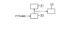
また、本発明は、図3に示すように、セットトップボックス(以下、STB:Set Top Box と称する。)30と、このSTB30に接続されて用いられる表示装置31及び印刷装置32とに対して適用することができる。STB30は、デジタル放送を受信する機能を備えている。すなわち、図3に示す例は、図1に示すデジタルテレビ受像機10のうち、受信部11、表示部12、及び印刷部13を一体とせずに、それぞれ別々に構成した場合の例である。
【0040】
また、本発明は、図4に示すように、セットトップボックス(以下、STB:Set Top Box と称する。)40と、このSTB40に接続されて用いられる表示装置41とに対して適用することができる。STB40は、デジタル放送を受信する受信部42と、デジタル放送に含まれる画像を印刷する印刷部43とを備えている。すなわち、図4に示す例は、図3に示すSTB30と印刷装置32とを一体として構成した場合の例である。
【0041】
上述したように、本発明は、デジタル放送を受信する受信部と、デジタル放送を表示する表示部と、デジタル放送に含まれる画像を印刷する印刷部とを様々に組み合わせた構成に対して適用することができる。そして、本発明では、受信部で受信したデジタル放送に含まれる画像データを印刷部に伝送するに際して、このデジタル放送に含まれる画像データを受信部から表示装置に対してデジタル信号によって伝送する第1の信号伝送手段を利用している。
【0042】
すなわち、本発明では、印刷部が受信部から画像データを取得するために、受信部から表示部に画像データを伝送するための、比較的高速で、且つデジタル信号を伝送する第1の信号伝送手段を用いていることが特徴的である。これにより、本発明は、印刷部で印刷する画像データを受信部から高速に転送することができる。また、デジタル放送に含まれる画像データを、デジタル信号を伝送する第1の信号伝送手段によって伝送していることから、受信部と印刷部とに対して、画像データを送受信するために、例えばD/A変換回路やA/D変換回路等の回路を設ける必要がない。また、デジタル信号を伝送する第1の信号伝送手段によって画像データを伝送することから、信号劣化やノイズの混入を防止することができ、低コストで高品質な印刷を行うことが可能となる。
【0043】
このような第1の信号伝送手段としては、例えば、導線や光ファイバ等の信号線を相互に接続する、いわゆる有線型の信号伝送手段であってもよいし、電波や赤外線等によって信号を伝送する、いわゆる無線型の信号伝送手段であってもよい。
【0044】
本発明は、上述したように、受信部、表示部、及び印刷部を様々に組み合わせた構成に対して適用することができるため、以下の説明においては、図3に示すように、これら各部をそれぞれ別々な構成として、STB30、表示装置31、及び印刷装置32とした場合における第1の実施例に基づいて詳細に説明することとする。
【0045】
第1の実施例
STB30は、例えば、図5に示すように、ダウンコンバータ50と、チューナ51と、デジタル復調部52と、誤り訂正部53と、デスクランブル部54と、パケット分離部55と、映像デコーダ56と、音声デコーダ57と、データデコーダ58と、合成器59と、ビデオRAM60と、デジタルビデオ信号出力部61と、モニタ制御信号出力部62とを備える。また、STB30は、I/O制御部63と、モデム64と、CPUシステム65と、プリンタ制御信号インタフェース66とを備える。なお、図5においては、STB30を構成する各部の間で送受信される各種信号の流れを矢印で示している。
【0046】
STB30は、地上波放送、衛星放送、有線放送などのように、様々な形態のデジタル放送を受信する構成とすることができるが、以下の説明においては、実用化が果たされているCSデジタル放送を受信する受信装置、いわゆるIRD(Integrated Receiver Decoder)として構成する場合について例示する。CSデジタル放送では、放送局や各種サービスプロバイダ及びコンテンツプロバイダなどの送信局によって、動画情報、静止画情報、及びSI情報(Service Information 情報)がデジタル信号として混在される。なお、SI信号とは、各種のサービス情報を記載したテーブルを所定の伝送フォーマットにした信号である。そして、送信局では、このデジタル信号を、地上波放送、衛星放送、又は有線放送として送出する。このデジタル信号は、必要に応じてスクランブル処理が施されて、送信局と所定の契約を交わしていない受信者が、デジタル放送を正しく再生することができないようにしてもよい。
【0047】
ダウンコンバータ50は、例えば、12GHz帯に割り当てられた電波を受信するアンテナに接続され、受信した電波を950MHz〜2GHz程度の中間周波数に変換する。なお、STB30において、ダウンコンバータ50は、上述したようなアンテナに接続されることに限定されるものではなく、デジタル放送が送出されてくる形態に応じて、例えば地上波放送を受信するアンテナや、衛星放送を受信するアンテナ、或いは、有線放送が送出されてくる信号線に接続されていればよい。
【0048】
チューナ51は、ダウンコンバータ50によって中間周波数に変換されたデジタル放送の信号に対して選局処理を行う。すなわち、デジタル放送の信号のうち、所定のチャンネルに相当する成分の信号を選択する。このチューナ51は、後述するように、例えば、使用者からのリモートコントローラによる指示に応じて、所定のチャンネルを選択することが可能とされている。
【0049】
デジタル復調器52は、チューナ51によって選局処理されたデジタル放送の信号に対して、QPSK(Quadrature Phase Shift Keying)復調を行う。このデジタル復調器52は、例えば、帯域幅を27MHzとし、出力ビットストリームを42.192Mbit/sの伝送レートとされる。
【0050】
誤り訂正部53は、デジタル復調器52によってQPSK復調が行われたデジタル放送の信号に対して、ビタビ復号、同期検出、リードソロモン復号(204,188)、デインタリーブ等を行い、例えば29.162Mbit/sのトランスポートストリーム(TS:Transport Stream)を抽出する。誤り訂正部53においては、例えば、ビタビ復号を行う際の畳み込みレートを1/2〜7/8程度とする。
【0051】
デスクランブル部54は、誤り訂正部53によって抽出されたトランスポートストリーム中に存在する特定のPID(Packet ID)を有するパケットについて、スクランブルの解除処理を行う。このようなスクランブルのアルゴリズムとしては、例えば、ブロック暗号に分類されるMULTI2等を利用することができる。また、STB30においては、このようにスクランブルの解除処理が行われた後の信号を、出力端子から高速にデータ出力を行うことによって、外部に取り出せるようにしてもよい。
【0052】
パケット分離部55は、デスクランブル部54によってスクランブルの解除処理が行われた後の信号の中から、所望とする番組のパケットだけを取り出す処理を行う。デスクランブル部54から得られる信号は、例えばMPEG2規格等によって、映像情報や音声情報が多重化されて送出されている信号である。パケット分離部55では、このように多重化されて送出された信号の中から、所望とする番組のパケットだけを取り出す。また、同時に、SI情報の取得、及びクロックの再生等を行う。パケット分離部55は、取り出したパケットを、映像デコーダ56、音声デコーダ57、及びデータデコーダ58に対して出力する。
【0053】
ところで、STB30においては、上述したダウンコンバータ50、チューナ51、デジタル復調器52、誤り訂正部53、デスクランブル部54、及びパケット分離部55が、デジタル放送を受信する受信手段として構成されている。なお、本発明において、STB30の受信手段は、係る構成に限定されるものではなく、デジタル放送を受信する機能を有していればよいことは云うまでもない。
【0054】
映像デコーダ56及び音声デコーダ57は、パケット分離部55から入力されたパケットに基づいて、例えばMPEG2規格により符号化された映像データ及び音声データをそれぞれ復号する。映像デコーダ56は、復号した映像データを合成器59に対して出力する。また、音声デコーダ57は、復号した音声データを、音声信号として外部に出力する。
【0055】
データデコーダ58は、パケット分離部55で取得されたSI情報、すなわち番組ガイド(EPG:Electronic Program Guide)情報や番組詳細情報等の各種データ情報の復号を行う。そして、復号後の信号のうち、表示可能なデータに直接展開できるSI情報を合成器59に出力するとともに、表示可能なデータに直接展開できないSI情報を、SI制御信号として、システムバスを介してCPUシステム65に出力する。このようにCPUシステム65に出力されたSI制御信号は、このCPUシステム65で処理された後に、SI表示信号として、合成器59に出力される。このとき、CPUシステム65では、SI制御信号に基づいて、例えば、フォントROMに備えるフォントデータを利用した変換処理を行うことにより、表示可能なSI表示信号に変換する。
【0056】
合成器59は、映像デコーダ56により復号された映像データ、データデコーダ58により復号されたSI情報、及びCPUシステム65から入力されるSI表示信号を合成して、表示装置31における1画面分の表示データを作成する。
【0057】
ところで、本発明においては、上述した映像デコーダ56、音声デコーダ57、データデコーダ58、合成器59、及びビデオRAM60が、STB30の描画手段として構成されている。なお、本発明において、STB30の描画手段は、係る構成に限定されるものではなく、上述した受信手段によって受信したデジタル放送の信号に基づいて所定の描画処理を行うことにより画像データを生成する機能を有していればよいことは云うまでもない。
【0058】
デジタルビデオ信号出力部61は、合成器59によって作成された表示データを、デジタル信号として外部に出力する。
【0059】
モニタ制御信号出力部62は、システムバスを介して、CPUシステム65から出力されたモニタ制御信号を、デジタル信号として外部に出力する。
【0060】
STB30においては、これらデジタルビデオ信号出力部61及びモニタ制御信号出力部62が、外部に接続される表示装置31に対してデジタル信号を送出する、いわゆるデジタルビデオインタフェースとして構成されている。なお、図5においては、デジタルビデオ信号出力部61とモニタ制御信号出力部62とを別々に示しているが、これらは一体に構成されていてもよく、所望とするデジタルビデオインタフェースに応じて構成すればよい。
【0061】
また、STB30では、デジタルビデオ信号出力部61及びモニタ制御信号出力部62で送出するデジタル信号の信号形式に限定されるものではないが、規格化された信号形式を用いることが望ましい。これにより、STB30は、同じ規格を有する表示装置31及び/又は印刷装置32に対して接続することが容易となる。
【0062】
規格化された信号形式としては、例えば、社団法人日本電子工業振興協会(JEIDA)が平成11年1月に制定したデジタルモニタインタフェース標準(Digital Interface Standards for Monitor)Version 1.0 がある。この規格では、次のような信号形式がサポートされている。
【0063】
1) デジタルデータ
TMDS(Transition Minimaized Differential Signaling)
LVDS(Low Voltage Differential Signaling)
GVIF(Giga-bit Video InterFace)
いずれか必須
2) 分離された水平・垂直同期信号 必須
3) データイネーブル信号 必須
4) DDC(Display Data Channel) 必須
5) VESAホットプラグ用信号(SENS) 必須
6) USB(Universal Serial Bus) オプション
そして、上述したような信号形式の組み合わせによって、以下の表1に示すような4つの標準が定められている。
【0064】
【表1】

なお、表1に示す4つの標準のうち、標準2b及び標準3は、同一の信号線を利用してビデオ信号と制御信号とを送出する標準である。STB30は、例えば、これら標準2b及び標準3に対応させる場合に、上述したように、デジタルビデオ信号出力部61とモニタ制御信号出力部62とを一体に構成し、同一の信号線を利用してビデオ信号と制御信号とを送出する構成とすることが望ましい。
【0066】
ところで、STB30においては、上述したデジタルビデオ信号出力部61及びモニタ制御信号出力部62が、上記描画手段により生成された画像データを、表示装置31及び印刷装置32に対して伝送する出力手段として構成されている。なお、本発明において、STB30の出力手段は、係る構成に限定されるものではなく、上述した描画手段により生成された画像データを画像データを、上述したように第1の信号伝送手段を介して伝送する機能を有していればよいことは云うまでもない。
【0067】
また、STB30において、I/O制御部63は、STB30内に設けられたシステムバスに接続され、例えばリモートコントローラによる使用者からの各種操作指示が入力される。また、I/O制御部63は、例えば、ICカードに対する記録再生を行う構成としてもよい。具体的には、例えば、スクランブル処理が施されたデジタル放送を受信する際に、使用者が送信局と所定の契約を交わしているか否かを示す情報や、有料デジタル放送を受信する際の課金情報などをICカードに記録しておき、このICカードから読み取った情報に基づいて、デジタル放送のスクランブル解除を行ったり、受信可能な残り時間を制御してもよい。また、I/O制御部63は、送信局に対する契約情報の取得や、モデム64を介して受信した電子メールの復号を行うとしてもよい。
【0068】
モデム64は、例えば電話回線やインターネット等の通信ネットワークを介して、各種情報を送受信する機能を有するとともに、STB30内に設けられたシステムバスに接続されている。STB30においては、必ずしもモデム64を備える必要はないが、モデム64を備えることにより、以下のような処理を行うことが可能となる。
【0069】
モデム64は、例えば、ICカードに対して記録再生を行う課金情報等を、デジタル放送の送信局や顧客管理センタなどに対して、通信ネットワークを介して送受信(アップリンク/ダウンリンク)する。あるいは、例えば、データデコーダ58から出力されたSI情報の中に、通信ネットワークを介して所定の情報アドレスにアクセスすることで所定の情報を取得する旨の指示が含まれている場合には、その情報をモデム64によって取得することが可能となる。このようにして取得した情報は、必要に応じてCPUシステム65により展開処理を行ってSI表示信号を生成してもよい。
【0070】
CPUシステム65は、例えば、CPU(Central Processing Unit)、プログラムROM(Read Only Memory)、フォントROM、RAM(Random Access Memory)、フラッシュメモリ等から構成されてなる。CPUシステム65は、STB30内に設けられたシステムバスに接続され、このシステムバスを介して各種制御信号の送受信を行うことにより、STB30を構成する各部に対する制御を行う。すなわち、CPUシステム65は、例えば、I/O制御部63に入力された使用者からの各種操作指示に応じて、STB30を構成する各部に対する制御を行う。なお、図5においては、システムバスとSTB30を構成する各部との間で送受信される各種制御信号の流れを示す矢印を、一部省略して示している。
【0071】
また、CPUシステム65は、上述したように、データデコーダ58から出力されたSI制御信号に基づいて、例えば、フォントROMに備えるフォントデータを利用した変換処理を行うことにより、表示可能なSI表示信号に変換する処理を行う。これにより、例えば、SI情報に基づいて、文字情報をオンスクリーン表示(OSD:On Screen Display)することが可能となる。
【0072】
プリンタ制御信号インタフェース66は、STB30内に設けられたシステムバスに接続され、印刷装置32に対してプリンタ制御信号の送受信を行う機能を有している。プリンタ制御信号は、STB30から外部に接続された印刷装置32に対して、例えば、印刷(プリント)動作の開始及び/又は中止を指示したり、プリントする画像のサイズや内容を指示する信号である。また、例えば、印刷装置32からSTB30に対して、プリント動作の完了や、用紙不足、用紙詰まり、インク不足などの情報を提供する信号である。
【0073】
プリンタ制御信号インタフェース66は、具体的な動作の一例を挙げると、例えば、I/O制御部63に入力された使用者からのプリント開始の指示を、システムバスを介して受信した場合に、印刷装置32に対して、プリント動作の開始を指示するプリンタ制御信号を送信する。そして、印刷装置32がプリント動作を正常に完了すると、この印刷装置32から送信されたプリント動作完了の情報を受信し、プリント動作が正常に完了したことを確認する。
【0074】
また、プリンタ制御信号インタフェース66は、印刷装置32が、例えば用紙不足や用紙詰まりなどによって、正常なプリント動作が不能となった場合に、この情報を受信して、プリント動作が正常に完了しなかったことを確認する。このとき、STB30においては、例えば、プリントが正常に完了していないことを示すSI制御信号をCPUシステム65によって生成し、合成器59及びデジタルビデオ信号出力部61を介して表示装置に所定の映像信号を送信することにより、プリント動作が正常に完了していないことを示す画像を表示装置31に表示させてもよい。
【0075】
ところで、本実施例においては、STB30と印刷装置32とが、上述した第1の信号伝送手段とは別に、この第1の信号伝送手段よりも伝送速度が遅い第2の信号伝送手段によって接続されている。そして、STB30のプリンタ制御信号インタフェース66は、この第2の信号伝送手段を介して印刷装置32に対してプリンタ制御信号を送受信する構成とされている。なお、本発明においては、係る構成に限定されるものではなく、例えば、STB30から送信される映像信号の隙間にプリンタ制御信号を混入させることにより、このプリンタ制御信号を第1の信号手段を介して送受信する構成とすることもできる。
【0076】
しかしながら、プリンタ制御信号は、第1の信号伝送手段によって送信される画像データと比較して、極めて情報量が少ないため、高速な第1の信号伝送手段を介して送受信する必要がない。そのため、STB30と印刷装置32とは、第1の信号伝送手段とは別に設けられた第2の信号伝送手段を用いてプリンタ制御信号の送受信を行うことによって、第1の信号伝送手段を画像データの伝送に占有することができ、この第1の信号伝送手段にプリント制御信号を混入させることによる伝送速度の低下などを防止することができる。
【0077】
また、本発明においては、後述する実施例で説明するように、この第2の信号伝送手段によって、プリント制御信号だけでなく、画像データよりも情報量の少ない各種信号を送受信するとしてもよい。
【0078】
このような第2の信号伝送手段としては、例えば、導線や光ファイバ等の信号線を相互に接続する、いわゆる有線型の信号伝送手段であってもよいし、電波や赤外線等によって信号を伝送する、いわゆる無線型の信号伝送手段であってもよい。具体的には、例えば、IEEE802.3(イーサネット)、IEEE1394、USB等の各種規格に基づいた信号伝送手段であってもよい。
【0079】
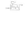
表示装置31は、例えば、図6に示すように、デジタルビデオ信号入力部70と、モニタ制御信号入力部71と、表示デバイス駆動部72と、表示デバイス73と、スピーカ74とを備える。なお、図6においては、表示装置31を構成する各部の間で送受信される各種信号の流れを矢印で示している。
【0080】
デジタルビデオ信号入力部70及びモニタ制御信号入力部71は、STB30から送信された映像信号、すなわちデジタルビデオ信号とモニタ制御信号とをそれぞれ受信して、この映像信号から表示装置31で表示する画像データを抽出する機能を有している。
【0081】
表示デバイス駆動部72は、デジタルビデオ信号入力部70及びモニタ制御信号入力部71によって抽出された画像データが入力され、この画像データに基づいて、表示デバイス73を駆動する駆動信号を生成する。駆動信号としては、例えば、RGB信号等である。
【0082】
表示デバイス73は、表示デバイス駆動部72によって生成された駆動信号に基づいて、所定の画像を表示する機能を有している。具体的には、例えば、CRT(Cathode Ray Tube)、LCD(Liquid Cristal Display)、プラズマディスプレイ等である。
【0083】
スピーカ74は、STB30から送信された音声信号を受信して、この音声信号を再生する機能を有している。
【0084】
つぎに、以下では、表示装置31における表示デバイス73上に表示される表示画像の一例について説明する。本発明は、上述したように、地上波放送、衛星放送、有線放送などの形態によって一般家庭に提供されるデジタル放送を受信するだけにとどまらず、例えば、既存のアナログ放送や、インターネット環境などのような様々なサービスの受信が可能な総合情報端末を提供する際に適用することができる。このような総合情報端末では、多数提供される番組の選択・視聴を容易且つ的確に実現するとともに、様々なサービスに対する容易な操作を実現することが重要となる。
【0085】
したがって、表示装置31における表示デバイス73上に表示される表示画像は、例えば、図7に示すような画像とすることが望ましい。なお、図7は、表示装置31を起動した直後に表示デバイス73上に表示される、初期画面の一例である。すなわち、表示装置31の初期画面においては、図7に示すように、例えば、受信中のハイビジョン放送を表示する領域S1、受信中のライブ番組の一覧を表示する領域S2、ホームサーバに記録されている番組の一覧を表示する領域S3、天気に関する情報を表示する領域S4、各種放送の番組表を表示する領域S5、テレビ新聞の見出し等のような文字情報を表示する領域S6などにより構成されている。
【0086】
また、表示装置31の初期画面は、例えば、各種ニュースや音楽などの音声サービスを選択する領域S7、電子メール等のような各種インターネット環境に対して選択・操作する領域S8、印刷装置32に対してプリント動作の指示を行う領域S9などにより構成されている。
【0087】
このように、様々な映像、音声、及びサービスを構成する表示画像は、STB30の合成器59によってひとつの画面に合成され、表示装置31の表示デバイス73上に表示される。そして、例えば、リモートコントローラ等によりI/O制御部63を介して、使用者から特定の操作指示が入力されると、STB30は、所定の映像、音声、又はサービスについて、拡大表示等の処理を行う。
【0088】
なお、表示装置31においては、表示装置31の起動後に所定の時間だけ図7に示すような初期画面が表示され、使用者からの操作指示がない場合に、自動的に特定の映像、音声、又はサービスを表示するように切り替えるとしてもよい。あるいは、使用者の要求に応じて、映像、音声、及びサービスの並びを自由にカスタマイズ可能とすることもできる。
【0089】
つぎに、表示装置31に表示される画面における、図7に示すような初期画面からのナビゲーションの一例について説明する。なお、図7においては、使用者から入力される所定の操作指示による、表示装置31に表示される内容の変化を矢印で示している。
【0090】
表示装置31は、その起動直後に、図8に示すように、初期画面が表示された状態S10とされている。この状態S10から、使用者により天気情報を表示する旨の操作指示が入力されると、表示装置31は、天気情報が表示デバイス73上に拡大表示された状態S11となる。なお、この状態S11から使用者により所定の操作指示が入力されると、初期画面が表示された状態S10に戻る。
【0091】
また、初期画面が表示された状態S10から、使用者により番組表を表示する旨の操作指示が入力されると、表示装置31は、番組表が表示デバイス73上に拡大表示された状態S12となる。
【0092】
この状態S12で、使用者から番組についての詳細な情報を表示する旨の操作指示が入力されると、STB30は、例えばモデム64等により、通信ネットワークを介してアクセスを行い、番組に関する詳細な情報を取得して、それを表示デバイス73上に表示した状態S13となる。
【0093】
また、初期画面が表示された状態S10、又は番組表が表示された状態S12において、使用者から所定の番組を選択する旨の操作指示が入力されると、特定の放送を表示デバイス73上に拡大表示した状態S14となる。
【0094】
番組表が表示デバイス73上に拡大表示された状態S12においては、使用者からの所定の操作指示により、特定の番組について録画予約を行う状態S15に移行してもよい。また、この状態S15において、予約を行った所定の時刻になった時点で、特定の放送を拡大表示した状態S14に移行してもよい。
【0095】
また、特定の放送を表示デバイス73上に拡大表示した状態S14において、使用者から所定の操作指示が入力されると、表示している放送に関連する情報を選択するリストを表示した状態S16となる。この状態S16から特定の関連情報を選択することにより、その関連情報を表示する状態S17となる。なお、このような関連情報は、STB30によって、例えばモデム64等により、通信ネットワークを介してアクセスを行い、特定の関連情報を取得する。
【0096】
また、初期画面が表示された状態S10において、使用者から所定の操作指示が入力されると、テレビ新聞の概要を表示した状態S18となる。この状態S18から、特定の記事の選択がなされると、その記事に関する本文を表示した状態S19となる。なお、このようなテレビ新聞の内容は、STB30におけるモデム64等により、通信ネットワークを介してアクセスを行って取得する。また、初期画面が表示された状態S10から直接、テレビ新聞の本文を表示した状態S19に移行するとしてもよい。
【0097】
また、初期画面が表示された状態S10において、使用者から所定の操作指示が入力されると、音声サービスがスピーカ74から音声出力された状態S20となる。あるいは、環境映像が表示された状態S21となる。なお、音声サービスが音声出力されるとともに、環境映像が表示された状態としてもよい。
【0098】
印刷装置32は、例えば、図9に示すように、デジタルビデオ信号入力部80と、モニタ制御信号入力部81と、プリントデータ抽出部と、プリント処理部83と、プリントヘッド駆動部84と、プリントヘッド85と、プリンタ制御信号インタフェース部86と、プリンタCPUシステム87とを備える。なお、図9においては、印刷装置32を構成する各部の間で送受信される各種信号の流れを矢印で示している。
【0099】
デジタルビデオ信号入力部80及びモニタ制御信号入力部81は、表示装置31におけるデジタルビデオ信号入力部70及びモニタ制御信号入力部71に相当し、STB30から送信された映像信号、すなわちデジタルビデオ信号とモニタ制御信号とをそれぞれ受信して、この映像信号から画像データを抽出する機能を有している。
【0100】
プリントデータ抽出部82は、デジタルビデオ信号入力部80及びモニタ制御信号入力部81によって抽出された画像データが入力されるとともに、この画像データから、印刷装置32でプリントする画像データだけを抽出する機能を有している。
【0101】
印刷装置32においては、このプリントデータ抽出部82によって、表示装置31で表示する画像データと同じ画像データを抽出してもよいが、例えば、STB30において、表示装置31で表示する画像データと印刷装置32でプリントする画像データとが混在された映像信号が送信されている場合には、このプリントデータ抽出部82によって、印刷装置32で印刷する画像データだけを抽出する。
【0102】
ところで、印刷装置32においては、デジタルビデオ信号入力部80、モニタ制御信号入力部81、及びプリントデータ抽出部82が、STB30から伝送された画像データを受信する受信手段として構成されている。なお、本発明において、印刷装置32の受信手段は、係る構成に限定されるものではなく、上述した第1の伝送手段により受信した画像データを受信する機能を有していればよいことは云うまでもない。
【0103】
プリント出力処理部83は、プリントデータ抽出部82によって変換処理された画像データに基づいて、プリントヘッドによってプリントするために適したプリントデータを生成する機能を有している。
【0104】
プリント出力処理部83は、具体的には例えば、LUT(ルックアップテーブル)による変換処理、積和演算等が高速に実行できる演算回路を利用した演算処理、高速演算処理アルゴリズムを持つソフトウエアによって実現する演算処理、及び/又は専用変換回路による処理等で実現されている。このように、プリント出力処理部83において演算処理を順次実行する場合には、入力される画像データにおける各データのビット数と同一のビット数で演算処理を行うと、各データの有効精度が悪化してしまう場合が多い。したがって、プリント出力処理部83では、入力される画像データのビット数に対して、演算処理の途中で、各データのビット数を増加させ、演算処理の最終段階において、増加させたビット数を元の状態に減少させることが望ましい。これにより、有効精度の悪化を回避することができる。
【0105】
ところで、印刷装置32においては、このプリント出力処理部83が、上述した印刷装置32の受信手段によって受信した画像データを処理して、印刷に適した印刷用画像データを生成する変換処理手段として構成されている。本発明においては、この変換処理手段は必須のものではないが、印刷装置32に変換処理手段を備えることにより、STB30から表示装置31に対して送信されている表示に適した画像データから、印刷に適した画像データを生成することができ、より高品質な印刷を行うことが可能となる。
【0106】
プリントヘッド駆動部84は、プリント出力処理部83によって生成されたプリントデータに基づいて、プリントヘッド85を駆動する駆動信号を生成する。
【0107】
プリントヘッド85は、プリントヘッド駆動部84によって生成された駆動信号に基づいて、駆動され、プリント用紙に所定の画像をプリントする機能を有している。なお、図9においては、図示を省略しているが、印刷装置32は、プリントヘッド85とともに、プリント用紙を供給する用紙供給部が備えられている。なお、用紙供給部は、従来から用いられている各種印刷装置と同様の構成であるため、説明を省略する。
【0108】
ところで、印刷装置32においては、これらプリントヘッド駆動部84及びプリントヘッド85が、画像データを印刷する印刷手段として構成されている。なお、本発明においては、係る構成に限定されるものではなく、上述した印刷装置32の受信手段により受信した画像データを印刷する機能を有していればよいことは云うまでもない。
【0109】
プリンタ制御信号インタフェース部86は、印刷装置32内に設けられたプリンタシステムバスに接続され、STB30に対してプリンタ制御信号の送受信を行う機能を有している。すなわち、プリンタ制御信号インタフェース部86は、STB30におけるプリンタ制御信号インタフェース66と同等のものであり、例えば、STB30から送信されるプリント動作の開始及び/又は中止の指示を受信したり、印刷装置32におけるプリント動作の完了や用紙不足などの情報をSTB30に送信する機能を有している。
【0110】
プリンタCPUシステム87は、例えば、CPU、プログラムROM、RAM、フラッシュメモリ等から構成されてなる。プリンタCPUシステム87は、印刷装置32内に設けられたプリンタシステムバスに接続され、このプリンタシステムバスを介して各種制御信号の送受信を行うことにより、印刷装置32を構成する各部に対する制御を行う。すなわち、プリンタCPUシステム87は、例えば、プリンタ制御信号インタフェース部86が受信したプリント動作の開始の指示に基づいて、印刷装置32を構成する各部に対する制御を行う。あるいは、プリンタCPUシステム87は、例えば、印刷装置32を構成する各部からの情報をプリンタシステムバスを介して受信し、プリント動作の完了や用紙不足などの情報を処理して、プリンタ制御信号インタフェース部86に送信する。
【0111】
なお、図9においては、プリンタシステムバスと印刷装置32を構成する各部との間で送受信される各種制御信号の流れを示す矢印を、一部省略して示している。
【0112】
つぎに、以下では、プリント出力処理部83の具体的な構成例について説明する。
【0113】
プリント出力処理部83は、図10に示すように、例えば、拡大部90と、RGB−CMY変換部91と、色補正部92と、黒抽出下色除去部93と、出力ガンマ補正及び階調修正部94と、シャープネス修正部95と、出力特性変換部96とを備える。なお、図10においては、プリント出力処理部83を構成する各部の間で送受信される各種信号の流れを矢印で示している。
【0114】
拡大部90は、プリントデータ抽出部82から例えばRGB信号によって出力された画像データの画素数が、プリントする画像の画素数と比較して少ない場合に、入力された画像データに対して拡大処理を行い、プリントするために適した画素数に変換する。
【0115】
拡大部90には、プリントデータ抽出部82から、例えば図11に示すように、上述したデジタル放送の動画画像の規格の一つである720p(720×1280画素)である画像データが入力される。このとき、拡大部90は、印刷装置32がA4サイズのプリント用紙に300dpiでプリントを行う場合に、図11に示すように、入力された画像データの縦横の構成画素数を2.675倍に拡大して、1926×3424画素である画像データに変換する。
【0116】
RGB−CMY変換部91は、拡大部90で変換処理された画像データに基づいて、この画像データを構成するRGB信号に変換処理を施し、プリントヘッド85で使用するC(Cyan)、M(Magenta)、Y(Yellow)の各色により構成されたインクやトナーに対応したCMY信号を生成する。この変換処理は、例えば、濃度Log変換、補色変換、又は線形マスキング変換などによって実現することができる。
【0117】
色補正部92は、RGB−CMY変換部91によって生成されたCMY信号に対して色補正処理を行う。これにより、印刷装置32は、プリントヘッド85で使用するインクやトナーの分光吸収特性が、減法混色による理想的な特性と異なっている場合に生じるプリント画像の色調、特に色相と彩度のずれを補正することができる。色補正部92において行う色補正処理は、具体的には、LUT(Look Up Table)を用いた演算による変換、線形マスキング演算による変換、又は非線形マスキング演算による演算などによって実現することができる。
【0118】
また、印刷装置32に入力される画像データにおける表現可能な色特性の範囲と、プリントヘッド85によってプリント用紙に再現可能な色特性の範囲とが異なる場合には、色補正部92において、画像データに対して色特性を圧縮処理やクリップ処理を行う。これにより、プリントヘッド85により再現可能な色特性の範囲を超える画像データが印刷装置32に入力された場合であっても、この画像データに含まれる色特性の情報を効率よく利用して最適なプリント処理を行うことが可能となる。
【0119】
黒抽出下色除去部93は、プリントヘッド85に黒色(以下、Kと記す。)のインク又はトナーが備えられている場合に、色補正部92によって色補正処理が行われた画像データに対して黒色の抽出及び下色の除去を行う。すなわち、黒抽出下色除去部93は、色補正部92から入力されたCMY信号中に含まれるK成分を抽出するとともに、C、M、Yの各成分から抽出したK成分に相当する値を減算し、C、M、Y、Kの各成分から構成されてなるCMYK信号を生成する。
【0120】
このように、CMY信号のうちK成分を抽出してCMYK信号に置換する方法としては、例えば、CMY信号中に含まれるK成分をすべて抽出する方法や、所定の割合のK成分を抽出・置換する方法、所定の濃度以上の領域でK成分を抽出・置換する方法など、様々な方法がある。
【0121】
印刷装置32においては、黒抽出下色除去部93によってCMY信号をCMYK信号に変換し、CMY信号中に含まれるK成分を黒色のインク又はトナーによってプリント処理することにより、C、M、Yの各インク又はトナーだけでは十分に再現することが困難な黒色部分を、最適な品質でプリントすることが可能となる。なお、印刷装置32において、プリントヘッド85に黒色のインク又はトナーが備えられていない場合には、黒色抽出除去部93は、上述した黒色抽出・置換処理を行わない。あるいは、この場合には、黒色抽出下色除去部93を備えずにプリント出力処理部83を構成してもよい。
【0122】
出力ガンマ補正及び階調修正部94は、黒抽出下色除去部93によってCMYK信号とされた画像データに対して、ガンマ補正処理、及び階調修正処理を行う。具体的には、プリントヘッド85における中間調の再現方法に特徴的な出力特性を有する場合に、入力された画像データに対して、その出力特性に適したガンマ補正処理、及び階調修正処理を行う。
【0123】
シャープネス修正部95は、出力ガンマ補正及び階調修正部94によって補正及び修正された画像データに対して、画像の輪郭部に対する強調処理、及びスムージング処理を行う。これにより、印刷装置32においては、プリントする画像の品質を向上させることができる。
【0124】
出力特性変換部96は、シャープネス修正部95によって処理された画像データに対して、プリントヘッド85の種類、プリントヘッド85の駆動方法、プリント用紙の種類、インク又はトナーの種類などに応じて、プリントする画像の品質が最適となるように、各種特性を変換する。また、プリント時の環境温度、プリントヘッド85における熱履歴特性、プリントヘッド85に備えられたプリント素子のばらつき等に応じて、各種特性を変換する。
【0125】
なお、画像データに対する各種特性の変換処理のうち、プリントヘッド駆動部84において、補正を行うことが適している変換処理については、このプリントヘッド駆動部84にて行うとすればよい。
【0126】
つぎに、プリントヘッド85において、黒色のインク又はトナーだけによってプリントする場合におけるプリント出力処理部82の構成の一例を、図12を参照しながら説明する。なお、図12において、図10に図示する部分と同一又は同等の部分については、図10と同一の符号を付し、詳細な説明を省略する。
【0127】
プリント出力処理部83は、プリントヘッド85において黒色のインク又はトナーだけによってプリントする場合に、図12に示すように、例えば、拡大部90と、RGB−K変換部100と、出力ガンマ補正及び階調修正部94と、シャープネス修正部95と、出力特性変換部96とを備える。すなわち、この場合にプリント出力処理部83は、上述したRGB−CMY変換部91、色補正部92、及び黒抽出下色除去部93との代わりに、RGB−K変換部を備えて構成される。
【0128】
RGB−K変換部100は、拡大部90からRGB信号によって出力された画像データに基づいて、所定の演算を行い、黒色(K)の濃度情報だけからなるK信号を生成する。このRGB−K変換部100では、例えば、以下の式1で求められる輝度情報Yに基づいてK信号を生成する。
【0129】
Y=0.2126×R+0.7152×G+0.0722×B (式1)
なお、上記式1において、R,G,Bは、それぞれ、RGB信号中のR成分、G成分、B成分の輝度を示す。
【0130】
また、図12に示すように、プリントヘッド85において黒色(K)だけでプリントを行うときには、プリントヘッド85が画像データに含まれる階調を全て再現することができない場合がある。この場合には、シャープネス修正部95又は出力特性変換部96において、プリントヘッド85で再現可能な階調の数に応じてディザ処理を行う。ディザ処理としては、例えば、組織的ディザ法や誤差拡散法などを利用して、疑似階調を表現する。
【0131】
つぎに、以下では、プリントヘッド85の具体的な構成例について説明する。なお、以下の説明では、印刷装置32のプリントヘッド85を、いわゆるモノクロレーザプリンタに適用した場合の一例について説明する。
【0132】
プリントヘッド85は、図13に示すように、例えば、レーザ出力部110と、ポリゴンミラー111と、モータ112と、レンズ113と、反射ミラー114と、感光ドラム115と、帯電チャージャ116と、現像器117と、転写チャージャ118と、一対の搬送ローラ119,120とを備える。
【0133】
このように、プリントヘッド85がモノクロレーザプリンタとして構成されている場合には、プリンタ出力処理部83によってK信号として変換された画像データが、プリントヘッド駆動部84(この場合には例えばレーザコントロール部やレーザドライバにより構成される。)によってレーザ出力信号に変換され、ポリゴンミラー111等と同期して、レーザ出力部110からレーザ光として出力される。
【0134】
レーザ出力部110から出力されたレーザ光は、ポリゴンミラー駆動部(図示せず。)によって駆動されるモータ112とともに回転するポリゴンミラー111に反射され、レンズ113及び反射ミラー114を経由して、感光ドラム115の主面を線状に走査する。感光ドラム115は、ドラム駆動モータ(図示せず。)によってレーザ光の走査方向を軸として回転駆動されている。また、感光ドラム115は、帯電チャージャ116によって帯電されており、レーザ光で走査されることで、画像データに応じた潜像が主面上に形成される。
【0135】
そして、感光ドラム115の主面上に形成された潜像に対して、現像器117によってトナーが供給され、トナー像が形成される。トナー像は、感光ドラム115の回転に伴って、転写チャージャ118に対向する位置までくると、図示を省略する給紙部から一対の搬送ローラ119,120によって搬送されてくるプリント用紙130に転写される。その後、プリント用紙130は、図示を省略する定着器によってトナーが定着され、印刷装置32の外に排出される。
【0136】
以上の説明では、印刷装置32におけるプリント方式として、従来から用いられているモノクロレーザプリンタを適用した場合について説明したが、本発明においては、このようなモノクロレーザプリンタ方式に限定されるものではなく、例えば、複数の感光ドラムを有するカラーレーザプリンタや、インクジェットプリンタ方式、感熱プリンタ、昇華型熱転写プリンタ等の各種プリント方式を適用することができることは云うまでもない。
【0137】
つぎに、以下では、上述したSTB30、表示装置31、及び印刷装置32の動作の一例について、図14乃至図16を参照しながら説明する。なお、以下の説明では、印刷装置32において、表示装置31に表示されている表示画像をそのままプリントする場合の例と、表示装置31に表示されている表示画像の一部、又はその表示画像に関連づけが行われているプリント画像をプリントする場合の例とについて説明する。
【0138】
前者の場合では、印刷装置32がデジタルビデオ信号入力部80及びモニタ制御信号入力部81によってSTB30から送信された映像信号を受信し、この映像信号から印刷装置32がプリントデータを生成する。また、後者の場合では、表示装置31に表示されている表示画像の一部、又はその表示画像に関連づけが行われているプリント画像を、STB30が生成し、表示装置31に対して送信する映像信号の間に、印刷装置32に対して送信するプリント画像に関する信号を送信している。そして、印刷装置32は、映像信号の間に送信されたプリント画像に関する信号を受信して、このプリント画像をプリントする。
【0139】
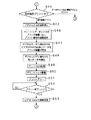
STB30は、動作開始後に、図14においてステップS30に示すように、各種放送を受信して合成器59によって各種画像を合成し、ビデオRAMにその画像を書き込む。このとき合成する画像は、例えば、図7に示すような初期画面とする。また、この初期画面を映像信号として表示装置31に送信し、表示装置31の表示デバイス73上に表示する。
【0140】
使用者からの操作指示が一定時間なかった場合には、ステップS31に示すように、前回選択された番組又は情報アドレスをCPUシステム65のフラッシュメモリ等から取得して、その番組放送又は情報アドレスを設定する。
【0141】
ステップS31において、番組放送の表示が設定された場合には、ステップS32に示すように、ダウンコンバータ50、チューナ51等により、所定の番組放送を受信する。
【0142】
次に、ステップS33に示すように、デスクランブル部54、映像デコーダ56等により、デコード処理を行う。
【0143】
次に、ステップS34に示すように、デコード処理が施された映像信号及びSI表示信号等を合成器59により合成して、ビデオRAM60に書き込む画像を更新する。
【0144】
また、ステップS31において、情報アドレスが設定された場合には、ステップS35に示すように、例えばモデム64等により、通信ネットワークにアクセスし、所定の情報を取得する。あるいは、ステップS35において、所定のデジタル放送を受信して所定の情報を取得する。
【0145】
次に、ステップS36に示すように、取得した所定の情報に対して、例えばデータデコーダ58やCPUシステム65によってデコード処理を行い、次のステップS34に処理を進める。
【0146】
ステップS34で更新された画像は、ステップS37に示すように、ビデオRAM60内で表示装置31に表示する画像として生成される。
【0147】
次に、ステップS38に示すように、ビデオRAM60内に生成された表示画像をデジタルビデオ信号出力部61を介して、映像信号として表示装置31に送信する。
【0148】
次に、ステップS39に示すように、表示装置31において、映像信号を受信し、表示デバイス73上に表示画像を表示する。
【0149】
次に、ステップS40に示すように、STB30のI/O制御部63は、例えば番組放送又は情報アドレスの選択操作が使用者により入力されたか否かを、判定する。入力された場合には、上述したステップS32又はステップS35に戻り、新たな番組放送又は情報アドレスを受信する。入力されていない場合には、次のステップS41に処理を進める。
【0150】
ステップS41において、I/O制御部63は、使用者からのプリント開始の操作指示が入力された否かを判定する。入力された場合には、図15に示すステップ42に処理を進める。入力されていない場合には、ステップS32又はステップS35に戻り、番組放送又は情報アドレスの受信を継続して、表示画像の更新を行う。
【0151】
次に、図15に示すステップS42において、使用者から入力されたプリント開始の指示が、表示装置31に表示されている表示画像をそのままプリントする指示であるか、又は、表示装置31の表示画像の一部、又はその表示画像に関連づけが行われているプリント画像をプリントする指示であるかを判定する。前者である場合には、次のステップS43に処理を進める。また、後者である場合には、図16に示すステップS44に処理を進める。
【0152】
次に、ステップS43において、STB30は、ビデオRAM60の更新を停止するとともに、表示装置31及び印刷装置32に対して送信する映像信号の内容を所定の画像に保ち、処理を次のステップS46に進める。
【0153】
ステップS46において、STB30は、プリンタ制御信号インタフェース66を介して、印刷装置32に対してプリント開始の指示を送信する。
【0154】
次に、ステップS47において、プリンタ装置32は、デジタルビデオ信号入力部80及びモニタ制御信号入力部81により、STB30から送信される映像信号を受信する。
【0155】
次に、ステップS48において、プリントデータ抽出部82により、受信した映像信号からプリントする画像データを抽出する。
【0156】
次に、ステップS49において、プリント出力処理部83により、抽出された画像データをプリントに適したプリントデータに変換処理する。
【0157】
次に、ステップS50において、プリントデータに基づいて、プリントヘッド駆動部84によりプリントヘッド85を駆動する。
【0158】
次に、ステップS51において、プリントヘッド85により、プリント動作を行う。
【0159】
次に、ステップS52において、プリンタCPUシステム87により、プリント動作が完了したか否かを判定する。完了した場合には、次のステップS53に処理を進める。完了していない場合には、プリント動作を継続するとともに、このステップS52における判定を繰り返す。
【0160】
次にステップS53において、印刷装置32は、プリンタ制御インタフェース部86を介して、プリント動作が完了した旨の情報をSTB30に送信する。STB30は、この情報をプリンタ制御インタフェース66によって受信すると、処理を図14に示したステップS32又はステップS35に戻し、ビデオRAM60の更新を再開する。
【0161】
また、上述したステップS42からステップS44に処理が進められた場合には、このステップS44において、STB30は、プリンタ制御信号インタフェース66を介して、印刷装置32に対してプリント開始の指示を送信する。
【0162】
次に、図16に示すステップS54において、印刷装置32のプリンタCPUシステム87は、プリントする画像を取得するために、新たに番組放送又は情報アドレスにアクセスする必要があるか否かを判定する。必要がある場合には、プリンタ制御信号インタフェース部86を介してSTB30に指示を送信し、次のステップS55又はステップS56に処理を進める。必要がない場合には、処理を次のステップS57に進める。
【0163】
ステップS55において、STB30は、プリンタ制御信号インタフェース66を介して印刷装置32からの指示を受信し、所定の番組放送を新たに受信し、次のステップS58に処理を進める。
【0164】
次に、ステップS58において、STB30は、受信した番組放送に対してデコード処理を施す。
【0165】
次に、ステップS59において、STB30は、デコード処理を施した番組放送に対して、データデコーダ58又はCPUシステム65等により、プリント用の画像データを生成し、処理を次のステップS57に進める。
【0166】
また、ステップS56において、STB30は、プリンタ制御信号インタフェース66を介して印刷装置32からの指示を受信し、所定の情報アドレスを新たに受信し、次のステップS60に処理を進める。
【0167】
次に、ステップS60において、STB30は、受信した情報アドレスに対してデコード処理を施し、処理をステップS59に進める。
【0168】
ステップS57において、STB30は、デジタルビデオ信号出力部61及びモニタ制御信号出力部62により、表示装置31に送信する画像データの送信期間外に、プリント用の画像データを映像信号として印刷装置に送信する。そして、処理を次のステップS61に進める。
【0169】
次に、ステップS61において、印刷装置32は、デジタルビデオ信号入力部80及びモニタ制御信号入力部81により、STB30から送信された映像信号を受信する。また、プリントデータ抽出部82により、受信した映像信号から、プリント用の画像データを抽出する。
【0170】
次に、ステップS62において、プリント出力処理部83により、抽出されたプリント用の画像データをプリントに適したプリントデータに変換処理する。
【0171】
次に、ステップS63において、プリントデータに基づいて、プリントヘッド駆動部84によりプリントヘッド85を駆動する。
【0172】
次に、ステップS64において、プリントヘッド85により、プリント動作を行う。
【0173】
次に、ステップS65において、プリンタCPUシステム87により、プリント動作が完了したか否かを判定する。完了した場合には、図14に示すステップS32又はステップS35に処理を進め、STB30における番組放送又は情報アドレスの受信、及びビデオRAM60の更新を再開する。完了していない場合には、プリント動作を継続するとともに、このステップS65における判定を繰り返す。
【0174】
第2の実施例
つぎに、以下では、本発明の第2の実施例について説明する。第2の実施例は、図17に示すように、上述した第1の実施例における印刷装置32に対して、プリントデータ抽出部82の後段にプリント画像RAM140を加えた構成とされている。なお、以下の説明においては、図7に示した印刷装置32と同一又は同等の部位についての説明を省略し、図17において同一の符号を付すこととする。
【0175】
プリント画像RAM140は、プリントデータ抽出部82によって抽出された画像データのうちの少なくとも一部を一時保持する機能を有している。そして、印刷装置32においては、プリント画像RAM140に保持された画像データがプリント出力処理部83に出力される構成とされている。
【0176】
印刷装置32においては、プリントする画像データをSTB30から受信する時間と比較して、プリント動作が完了するまでに多くの時間を要してしまう。したがって、上述した第1の実施例においては、図15においてステップS43で説明したように、印刷装置32のプリント動作が完了するまでSTB30のビデオRAM60の更新を停止し、このビデオRAM60に一時保持された所定の画像データを継続して送信している。そのため、第1の実施例では、印刷装置32がプリント動作を完了するまで、表示装置31に表示される表示画面の更新が行われず、所定の静止画像が表示されたままになってしまう。このことは、使用者にとって、印刷装置32によるプリント動作が行われていることを容易に確認できるという利点がある一方で、番組放送の視聴が中断されてしまうという欠点ともなり得る。
【0177】
しかしながら、第2の実施例における印刷装置32は、プリント画像RAM140を備えていることにより、STB30から送信される画像データのうちの少なくとも一部を一時保持することができるため、プリントする画像データがプリント画像RAM140に十分に記録された段階で、プリント動作の完了を待つことなくSTB30のビデオRAMの更新を再開することが可能となり、番組放送の視聴を中断する時間を低減することができるようになる。
【0178】
なお、本発明においては、プリント画像RAM140の記憶容量に限定されるものではないが、プリントする画像データの全てを一度に保持するに十分な記憶容量を備えていることが望ましい。これにより、プリント動作の完了までに所定の時間を要する場合であっても、STB30のビデオRAM60の更新を停止する必要がなくなり、番組放送の視聴を中断することなくプリント動作を行うことが可能となる。
【0179】
なお、プリント画像RAM140は、プリントデータ抽出部82の後段ではなく、プリント出力処理部83の後段に設けるとしてもよい。プリント出力処理部83における処理に要する時間が十分に短ければ、この場合であっても、上述と同様に、番組放送の視聴を中断する時間を低減することができる。
【0180】
第3の実施例
つぎに、以下では、本発明の第3の実施例について説明する。第3の実施例は、STB30で受信されたデジタル放送に含まれる情報の一部を、印刷装置32側で展開処理する場合の例である。
【0181】
この第3の実施例では、図18に示すように、上述した第1の実施例におけるSTB30に対して、SIプリント信号出力部150を加え、図19に示すように、上述した第1の実施例における印刷装置32に対して、SIプリント信号入力部151、データデコーダ152、合成器153、及びプリント画像RAM154を加えた構成とされている。また、印刷装置32のプリンタCPUシステム87は、フォントROMを備えた構成とされている。そして、STB30のSIプリント信号出力部150と、印刷装置32のSIプリント信号入力部151とは、上述した第2の信号伝送手段、又はこの第2の信号伝送手段と同等の信号伝送手段によって接続されている。
【0182】
なお、以下の説明においては、図5及び図7にそれぞれ示したSTB30及び印刷装置32と同一又は同等の部位についての説明を省略し、図18及び図19においては同一の符号を付すこととする。
【0183】
本実施例におけるSTB30は、パケット分離部55において、例えばMPEG−2規格によって映像信号や音声信号が多重化された入力ストリームの中から、目的とする番組のパケットが分離されるとともに、さらにデータデコーダ58によって映像信号や音声信号以外の情報、すなわちSI制御信号が分離されてCPUシステム65に出力される。STB30のCPUシステム65は、データデコーダ58から出力されたSI制御信号に基づいて、印刷装置32で展開処理する情報をSIプリント信号として生成・抽出し、SIプリント信号出力部150に出力する。SIプリント信号出力部150は、SIプリント信号を、第2の信号伝送手段、又はこの第2の信号伝送手段と同等の信号伝送手段を介して印刷装置32に送信する。
【0184】
なお、SIプリント信号は、画像データよりも情報量が少ない信号であり、例えば、印刷装置32のデータデコーダ152によって所定の処理が施されることにより、例えば、サービス情報や文字情報等が生成される信号である。
【0185】
印刷装置32は、STB30から送信されたSIプリント信号を、SIプリント信号入力部151によって受信する。そして、SIプリント信号入力部151によって受信されたSIプリント信号は、データデコーダ152に入力される。データデコーダ152は、SIプリント信号の復号を行い、復号後の信号のうち、表示可能なデータに直接展開できるSIプリント信号を合成器153に出力するとともに、表示可能なデータに直接展開できないSIプリント信号を、SI制御信号として、システムバスを介してプリンタCPUシステム87に出力する。
【0186】
このようにプリンタCPUシステム87に出力されたSI制御信号は、このプリンタCPUシステム87で処理された後に、SI記録信号として、合成器153に出力される。このとき、プリンタCPUシステム87では、SI制御信号に基づいて、例えば、フォントROMに備えるフォントデータを利用した変換処理を行うことにより、表示可能なSI記録信号に変換する。
【0187】
合成器153は、STB30における合成器59と同等なものであり、プリントデータ抽出部82で抽出された画像データ、データデコーダ152から出力されたSIプリント信号、及びプリンタCPUシステム87で変換処理されたSI記録信号が入力されるとともに、これらを合成し、プリント画像RAM154に書き込む。プリント画像RAM154に合成して書き込まれた画像データは、プリント出力処理部83に出力される。
【0188】
本実施例では、画像データのように情報量が比較的多いデータは、高速な第1の信号伝送手段を介してSTB30から印刷装置32に伝送されており、画像データよりも情報量が少ないサービス情報や文字情報などのようなデータは、第1の信号伝送手段よりも低速な第2の信号伝送手段を介してSTB30から印刷装置32に伝送されている。したがって、本実施例では、例えばサービス情報や文字情報などを、印刷装置32側で生成・合成することが可能であるとともに、をSTB30側で生成する必要がないとともに、第1の信号伝送手段を画像データの伝送に占有することができ、この第1の信号伝送手段に画像データ以外の信号を混入させることによる伝送速度の低下を防止することができる。
【0189】
第4の実施例
つぎに、以下では、本発明の第4の実施例について説明する。第4の実施例は、上述した第3の実施例のように、STB30で受信されたデジタル放送に含まれる情報の一部を、印刷装置32側で展開処理する場合の別の例である。
【0190】
この第4の実施例では、図20に示すように、上述した第1の実施例におけるSTB30に対して、データストリーム信号出力部160を加え、図21に示すように、上述した第1の実施例における印刷装置32に対して、データストリーム信号入力部161、パケット分離部162、データデコーダ163、合成器164、及びプリント画像RAM165を加えた構成とされている。また、印刷装置32のプリンタCPUシステム87は、フォントROMを備えた構成とされている。そして、STB30のデータストリーム信号出力部160と、印刷装置32のデータストリーム信号入力部161とは、上述した第2の信号伝送手段、又はこの第2の信号伝送手段と同等の信号伝送手段によって接続されている。
【0191】
なお、以下の説明においては、図5及び図7にそれぞれ示したSTB30及び印刷装置32と同一又は同等の部位についての説明を省略し、図20及び図21においては同一の符号を付すこととする。
【0192】
本実施例におけるSTB30は、デスクランブル部54においてスクランブルの解除処理が行われたデータストリーム信号を、パケット分離部55及びデータストリーム信号出力部160に出力する。データストリーム信号出力部160は、データストリーム信号を、第2の信号伝送手段、又はこの第2の信号伝送手段と同等の信号伝送手段を介して印刷装置32に送信する。
【0193】
なお、データストリーム信号は、パケット分離部55によって所望とする番組のパケットの取り出し処理が行われる以前の信号であり、印刷装置32のパケット分離部162により、例えば、サービス情報や文字情報等が生成される信号である。
【0194】
印刷装置32は、STB30から送信されたデータストリーム信号を、データストリーム信号入力部161によって受信する。そして、データストリーム信号入力部161によって受信されたデータストリーム信号は、パケット分離部162に入力される。パケット分離部162は、STB30におけるパケット分離部55と同等の機能を有するものであり、データストリーム信号の中から、所望とする情報を含むパケットだけを取り出す処理を行う。パケット分離部162は、取り出したパケットを、データデコーダ163に対して出力する。
【0195】
データデコーダ163は、パケット分離部162によって取り出されたパケットのの復号を行い、復号後の信号のうち、プリント可能なデータに直接展開できるSIプリント信号を合成器164に出力するとともに、プリント可能なデータに直接展開できないSI制御信号を、システムバスを介してプリンタCPUシステム87に出力する。
【0196】
このようにプリンタCPUシステム87に出力されたSI制御信号は、このプリンタCPUシステム87で処理された後に、SI記録信号として、合成器164に出力される。このとき、プリンタCPUシステム87では、SI制御信号に基づいて、例えば、フォントROMに備えるフォントデータを利用した変換処理を行うことにより、プリント可能なSI記録信号に変換する。
【0197】
合成器164は、STB30における合成器59と同等なものであり、プリントデータ抽出部82で抽出された画像データ、データデコーダ163から出力されたSIプリント信号、及びプリンタCPUシステム87で変換処理されたSI記録信号が入力されるとともに、これらを合成し、プリント画像RAM165に書き込む。プリント画像RAM165に合成して書き込まれた画像データは、プリント出力処理部83に出力される。
【0198】
本実施例では、上述した第3の実施例と同様に、画像データのように情報量が比較的多いデータは、高速な第1の信号伝送手段を介してSTB30から印刷装置32に伝送されており、画像データよりも情報量が少ないサービス情報や文字情報などのようなデータは、第1の信号伝送手段よりも低速な第2の信号伝送手段を介してSTB30から印刷装置32に伝送されている。したがって、本実施例では、例えばサービス情報や文字情報などを、印刷装置32側で生成・合成することが可能であるとともに、をSTB30側で生成する必要がないとともに、第1の信号伝送手段を画像データの伝送に占有することができ、この第1の信号伝送手段に画像データ以外の信号を混入させることによる伝送速度の低下を防止することができる。
【0199】
第5の実施例
つぎに、以下では、本発明の第5の実施例について説明する。第5の実施例は、STB30とは別に、印刷装置32側にもデジタル放送の受信機能を備えて構成した場合の例である。
【0200】
この第5の実施例では、図22に示すように、上述した第1の実施例における印刷装置32に対して、ダウンコンバータ170、チューナ171、デジタル復調部172、誤り訂正部173、デスクランブル部174、パケット分離部175、データデコーダ176、合成器、プリント画像RAM178、及びモデム179を加えた構成とされている。また、印刷装置32のプリンタCPUシステム87は、フォントROMを備えた構成とされている。
【0201】
なお、以下の説明においては、図7に示した印刷装置32と同一又は同等の部位についての説明を省略し、図22においては同一の符号を付すこととする。
【0202】
ダウンコンバータ170、チューナ171、デジタル復調部172、誤り訂正部173、デスクランブル部174、パケット分離部175、及びデータデコーダ176は、上述したSTB30におけるダウンコンバータ50、チューナ51、デジタル復調部52、誤り訂正部53、デスクランブル部54、パケット分離部55、及びデータデコーダ58にそれぞれ相当する。すなわち、本実施例では、印刷装置32においても、STB30に備えられたデジタル放送の受信手段と略同等なデジタル放送の受信手段が設けられている構成とされている。
【0203】
ただし、印刷装置32においては、パケット分離部175で取り出したパケットを、データデコーダ176だけに対して出力する。そして、データデコーダ176においては、映像データや音声データの復号を行わず、SI情報だけについての復号を行う。データデコーダ176は、復号後の信号のうち、プリント可能なデータに直接展開できるSI情報を合成器177に出力するとともに、プリント可能なデータに直接展開できないSI情報を、SI制御信号として、システムバスを介してプリンタCPUシステム87に出力する。
【0204】
このようにプリンタCPUシステム87に出力されたSI制御信号は、このプリンタCPUシステム87で処理された後に、SI記録信号として、合成器177に出力される。このとき、プリンタCPUシステム87では、SI制御信号に基づいて、例えば、フォントROMに備えるフォントデータを利用した変換処理を行うことにより、プリント可能なSI記録信号に変換する。
【0205】
合成器177は、STB30における合成器59と同等なものであり、プリントデータ抽出部82で抽出された画像データ、データデコーダ176から出力されたSIプリント信号、及びプリンタCPUシステム87で変換処理されたSI記録信号が入力されるとともに、これらを合成し、プリント画像RAM178に書き込む。プリント画像RAM178に合成して書き込まれた画像データは、プリント出力処理部83に出力される。
【0206】
以上のように、本実施例では、STB30とは別に、印刷装置32側にもデジタル放送の受信機能を備えて構成されている。これにより、印刷装置32は、例えば、プリンタ制御信号インタフェース部86によって受信したプリンタ制御信号に含まれる所定の信号に基づいて、表示装置31で表示する画像データとは異なる所定の番組放送からサービス情報及び/又は文字情報を取得することが可能となる。したがって、印刷装置32は、表示装置31で表示する画像データをプリントするだけでなく、番組放送及び/又は情報アドレスに独自にアクセスすることが可能となり、より柔軟なプリント動作を行うことが可能となる。
【0207】
また、モデム179は、上述したSTB30におけるモデム64と略同等のものであり、例えば電話回線等の通信ネットワークを介して、各種情報を送受信する機能を有するとともに、印刷装置32内に設けられたプリンタシステムバスに接続されている。
【0208】
本実施例では、印刷装置32がモデム179を備えていることにより、STB30のモデム64とは異なる通信ネットワークに対して独自にアクセスすることが可能となり、より柔軟にサービス情報及び/又は文字情報を取得することが可能となる。
【0209】
以上で第1乃至第5の実施例を挙げて説明したが、これら実施例は、冒頭で述べたような受信部、表示部、及び印刷部の組み合わせのうち、これら各部をそれぞれ別々な構成として、STB30、表示装置31、及び印刷装置32とした場合の例である。
【0210】
しかしながら、本発明は、受信部、表示部、及び印刷部をそれぞれ別々に構成した場合への適用に限定されるものではなく、例えば、図1に示したデジタルテレビ受像機10、図2に示したデジタルテレビ受像機20及び印刷装置21、図4に示したSTB40及び表示装置41などのように、受信部、表示部、及び印刷部のうちの少なくとも一部を一体に構成した場合に対しても適用することが可能である。このような場合であっても、以上で説明した第1乃至第5の実施例における本発明の効果を発揮することができる。
【0211】
なお、このように、受信部、表示部、及び印刷部のうちの少なくとも一部を一体に構成した場合には、以上の実施例で説明した各構成要素の一部を適宜省略することが可能となる。例えば、図4に示したSTB40及び表示装置41に対して本発明を適用する場合には、上述した第1の実施例におけるSTB30のシステムバスと印刷装置31のプリンタシステムバスとを接続し、プリンタCPUシステム87を省略して、STB30のCPUシステム65によって、印刷部を構成する各部の制御を行うとしてもよい。また、この場合には、STB30のプリンタ制御信号インタフェース66と印刷装置31のプリンタ制御信号インタフェース部86とを省略することができる。
【0212】
【発明の効果】
以上で説明したように、本発明に係るデジタル放送受信システムは、印刷装置が受信装置から画像データを受信するに際して、受信装置から表示装置に対して画像データを伝送するために用いている第1の信号伝送手段を用いることから、印刷する画像データを高速に転送することができる。また、デジタル放送に含まれる画像データを、デジタル信号を伝送する第1の信号伝送手段によって伝送していることから、例えばD/A変換回路やA/D変換回路等の回路を設ける必要がないとともに、信号劣化やノイズの混入を防止することができ、低コストで高品質な印刷を行うことが可能となる。また、印刷用画像データを一時保持する印刷画像用記憶手段を設けたことで、印刷画像用記憶手段を備えていることにより、受信装置から送信される画像データを一時保持することができるため、プリントする画像データが印刷画像用記憶手段に十分に記録された段階で、プリント動作の完了を待つことなく、受信装置の画像用記憶手段の更新を再開することが可能となり、番組放送の視聴を中断する時間を低減することができるようになる。また、受信装置とは別に、印刷装置側にもデジタル放送の受信機能を備えて構成されている。これにより、印刷装置は、表示装置で表示する画像データとは異なる所定の番組放送からサービス情報及び/又は文字情報を取得することが可能となる。したがって、印刷装置は、表示装置で表示する画像データをプリントするだけでなく、番組放送及び/又は情報アドレスに独自にアクセスすることが可能となり、より柔軟なプリント動作を行うことが可能となる。
【0213】
また、本発明に係るデジタル放送受信装置は、印刷部が受信部から画像データを受信するに際して、受信部から外部に接続される表示装置に対して画像データを伝送するために用いている第1の信号伝送手段を用いることから、印刷する画像データを高速に転送することができる。また、デジタル放送に含まれる画像データを、デジタル信号を伝送する第1の信号伝送手段によって伝送していることから、例えばD/A変換回路やA/D変換回路等の回路を設ける必要がないとともに、信号劣化やノイズの混入を防止することができ、低コストで高品質な印刷を行うことが可能となる。また、印刷用画像データを一時保持する印刷画像用記憶手段を設けたことで、印刷画像用記憶手段を備えていることにより、受信装置から送信される画像データを一時保持することができるため、プリントする画像データが印刷画像用記憶手段に十分に記録された段階で、プリント動作の完了を待つことなく、受信装置の画像用記憶手段の更新を再開することが可能となり、番組放送の視聴を中断する時間を低減することができるようになる。また、受信部とは別に、印刷部側にもデジタル放送の受信機能を備えて構成されている。これにより、印刷部は、表示装置で表示する画像データとは異なる所定の番組放送からサービス情報及び/又は文字情報を取得することが可能となる。したがって、印刷部は、表示装置で表示する画像データをプリントするだけでなく、番組放送及び/又は情報アドレスに独自にアクセスすることが可能となり、より柔軟なプリント動作を行うことが可能となる。
【0215】
また、本発明に係る印刷装置は、受信装置から表示装置に画像データを伝送する第1の信号伝送手段を介して、当該印刷装置にも画像データを伝送されることができる。また、デジタル放送に含まれる画像データを伝送するに際して、デジタル信号を伝送する第1の信号伝送手段を用いることから、例えばD/A変換回路やA/D変換回路等の回路を設ける必要がないとともに、信号劣化やノイズの混入を防止することができ、低コストで高品質な印刷を行うことが可能となる。また、印刷用画像データを一時保持する印刷画像用記憶手段を設けたことで、印刷画像用記憶手段を備えていることにより、受信装置から送信される画像データを一時保持することができるため、プリントする画像データが印刷画像用記憶手段に十分に記録された段階で、プリント動作の完了を待つことなく、受信装置の画像用記憶手段の更新を再開することが可能となり、番組放送の視聴を中断する時間を低減することができるようになる。また、受信装置とは別に、印刷装置側にもデジタル放送の受信機能を備えて構成されている。これにより、印刷装置は、表示装置で表示する画像データとは異なる所定の番組放送からサービス情報及び/又は文字情報を取得することが可能となる。したがって、印刷装置は、表示装置で表示する画像データをプリントするだけでなく、番組放送及び/又は情報アドレスに独自にアクセスすることが可能となり、より柔軟なプリント動作を行うことが可能となる。
【0216】
さらに、本発明に係る印刷方法は、印刷装置が受信装置から画像データを受信するに際して、受信装置から表示装置に対して画像データを伝送するために用いている第1の信号伝送手段を用いることから、印刷する画像データを高速に転送することができる。また、デジタル放送に含まれる画像データを、デジタル信号を伝送する第1の信号伝送手段を用いていることから、例えばD/A変換回路やA/D変換回路等の回路を設ける必要がないとともに、信号劣化やノイズの混入を防止することができ、低コストで高品質な印刷を行うことが可能となる。また、印刷用画像データを一時保持する印刷画像用記憶手段を設けたことで、印刷画像用記憶手段を備えていることにより、受信装置から送信される画像データを一時保持することができるため、プリントする画像データが印刷画像用記憶手段に十分に記録された段階で、プリント動作の完了を待つことなく、受信装置の画像用記憶手段の更新を再開することが可能となり、番組放送の視聴を中断する時間を低減することができるようになる。また、受信装置とは別に、印刷装置側にもデジタル放送の受信機能を備えて構成されている。これにより、印刷装置は、表示装置で表示する画像データとは異なる所定の番組放送からサービス情報及び/又は文字情報を取得することが可能となる。したがって、印刷装置は、表示装置で表示する画像データをプリントするだけでなく、番組放送及び/又は情報アドレスに独自にアクセスすることが可能となり、より柔軟なプリント動作を行うことが可能となる。
【図面の簡単な説明】
【図1】本発明を適用したデジタルテレビ受像機を示す概略構成図である。
【図2】本発明を適用したデジタルテレビ受像機及び印刷装置を示す概略構成図である。
【図3】本発明を適用したSTB、表示装置、及び印刷装置を示す概略構成図である。
【図4】本発明を適用したSTB及び表示装置を示す概略構成図である。
【図5】本発明を適用したSTBを示す概略構成図である。
【図6】本発明を適用した表示装置を示す概略構成図である。
【図7】本発明を適用した表示装置に表示される初期画面の一例を示す概略図である。
【図8】本発明を適用した表示装置に表示される画面におけるナビゲーションの一例を示す概略図である。
【図9】本発明を適用した印刷装置を示す概略構成図である。
【図10】本発明を適用した印刷装置におけるプリント出力処理部の一構成例を示す概略図である。
【図11】本発明を適用した印刷装置における拡大部での処理を説明するための概略図である。
【図12】本発明を適用した印刷装置におけるプリント出力処理部の別の構成例を示す概略図である。
【図13】本発明を適用した印刷装置におけるプリントヘッドの一構成例を示す概略図である。
【図14】本発明を適用したSTB、表示装置、及び印刷装置の動作の一例を説明するフローチャートである。
【図15】本発明を適用したSTB、表示装置、及び印刷装置の動作の一例を説明するフローチャートである。
【図16】本発明を適用したSTB、表示装置、及び印刷装置の動作の一例を説明するフローチャートである。
【図17】本発明を適用した印刷装置の別の構成例を示す概略図である。
【図18】本発明を適用したSTBの別の構成例を示す概略図である。
【図19】本発明を適用した印刷装置の別の構成例を示す概略図である。
【図20】本発明を適用したSTBの別の構成例を示す概略図である。
【図21】本発明を適用した印刷装置の別の構成例を示す概略図である。
【図22】本発明を適用した印刷装置の別の構成例を示す概略図である。
【図23】従来のアナログビデオプリンタの使用形態を示す概略図である。
【図24】従来のアナログマルチスキャンプリンタの使用形態を示す概略図である。
【図25】従来のPCプリンタの使用形態を示す概略図である。
【符号の説明】
30 STB、31 表示装置、32 印刷装置、50 ダウンコンバータ、51 チューナ、52 デジタル復調器、53 誤り訂正部、54 デスクランブル部、55 パケット分離部、56 映像デコーダ、57 音声デコーダ、58 データデコーダ、59 合成器、60 ビデオRAM、61デジタルビデオ信号出力部、62 モニタ制御信号出力部、63 I/O制御部、64 モデム、65 CPUシステム、66 プリンタ制御信号インタフェース、80デジタルビデオ信号入力部、81 モニタ制御信号入力部、82 プリントデータ抽出部、83 プリント出力処理部、84 プリントヘッド駆動部、85 プリントヘッド、86 プリンタ制御信号インタフェース部、87 プリンタCPUシステム[0001]
BACKGROUND OF THE INVENTION
The present invention relates to a digital broadcast receiving system including a receiving device that receives a digital broadcast, a display device that displays the digital broadcast received by the receiving device, and a printing device that prints an image included in the digital broadcast received by the receiving device. About. The present invention also relates to a digital broadcast receiving apparatus including a receiving unit that receives a digital broadcast and a printing unit that prints an image included in the received digital broadcast. Furthermore, the present invention relates to a receiving device that receives a digital broadcast and a printing device that prints an image included in the digital broadcast. Furthermore, the present invention relates to a printing method for receiving a digital broadcast by a receiving device and printing an image included in the digital broadcast by a printing device.
[0002]
[Prior art]
Conventionally, an analog video printer has been used to print out a display image of a television broadcast or the like displayed on a display device such as a CRT (Cathode Ray Tube) display.
[0003]
For example, as shown in FIG. 23, the analog video printer receives an analog video signal output from the
[0004]
The
[0005]
The
[0006]
Such an
[0007]
In the conventional
[0008]
An analog multi-scan printer or a PC printer is used to print out a display image of an information processing apparatus such as a personal computer (hereinafter referred to as a PC).
[0009]
For example, as shown in FIG. 24, the analog
[0010]
Note that the analog
[0011]
Horizontal resolution: 640-1600 dots
Vertical resolution: 480-1200 lines
Horizontal deflection frequency: 30 to 107 kHz
Vertical deflection frequency: 48-160Hz
The analog
[0012]
For example, as shown in FIG. 25, the
[0013]
In the
[0014]
In such a
[0015]
[Problems to be solved by the invention]
Conventionally, for example, when a television broadcast is received and displayed, an analog television signal is received by a receiving device, and the analog television signal is processed by an analog electronic circuit and displayed on a display device. It was. However, it is expected that such television broadcasting will be broadcast not by analog signals but by digital signals as in the past.
[0016]
Specifically, for example, in Japan, CS digital broadcasting is started from October 1996, and further digital broadcasting is about to be started sequentially by CATV, BS broadcasting, and terrestrial broadcasting. As described above, when the television broadcast is digitized, a higher quality video than before can be provided. In addition to the video signal, a signal including various information called an SI (Service Information) signal is provided by digitization, and an EPG (Electronic Program Guide), that is, a program that can be displayed on a display device by the SI signal. Guide information can be used.
[0017]
As described above, the digitization of the television broadcast makes it possible to display not only the program video as in the past but also various content information in combination on the display device. Accordingly, a television broadcast display device is required to be able to display, for example, character information with high definition. In addition, the receiving device is required to perform various processes on the received digital signal as digital data and send the digital signal as it is to the display device.
[0018]
On the other hand, in recent years, various organizations have been examining digital data interface standards for display devices connected to video ports of various application devices such as personal computers and set-top boxes (hereinafter referred to as STBs). ing. As an example of such a digital data interface standard, the Japan Electronic Industry Development Association (JEIDA) established Version 1.0 of the Digital Interface Standards for Monitor in January 1999. .
[0019]
In the case of using the above-described conventional
[0020]
Specifically, for example, when the above-described
[0021]
For example, when the above-described analog
[0022]
When the
[0023]
Further, for example, when connecting a television receiver that receives and displays a television broadcast and a printing apparatus, if image data is transmitted using a general-purpose printer interface similar to the
[0024]
Therefore, the present invention solves the above-described problems, and can transfer image data at a high speed when printing an image included in a digital broadcast, and a circuit or function that is wasted. It is an object to provide a digital broadcast receiving system, a digital broadcast receiving apparatus, a receiving apparatus, a printing apparatus, and a printing method that can be realized at low cost.
[0025]
[Means for Solving the Problems]
A digital broadcast receiving system according to the present invention includes:In a digital broadcast receiving system comprising: a receiving device that receives a digital broadcast; a display device that displays the digital broadcast received by the receiving device; and a printing device that prints an image included in the digital broadcast received by the receiving device. The receiving device is connected to the display device and the printing device by first signal transmission means for transmitting a digital signal. The receiving device is generated by a receiving unit that receives a digital broadcast, a drawing unit that generates image data by performing a predetermined drawing process based on a signal of the digital broadcast received by the receiving unit, and the drawing unit. Until the receiving means of the printing apparatus finishes receiving the image data, the image storage means for temporarily holding the image data, and the image data generated by the drawing means are the image storage means. And output means for reading out and transmitting via the first signal transmission means. The printing apparatus includes a receiving unit that receives the image data transmitted via the first signal transmission unit, and a conversion processing unit that processes the image data received by the receiving unit to generate image data for printing. A printing image storage means for temporarily storing the printing image data generated by the conversion processing means; and a printing means for reading out the printing image data generated by the conversion processing means from the printing image storage means for printing. And. The receiving device and the printing device are connected by a second signal transmission unit having a transmission speed slower than that of the first signal transmission unit, and the receiving device and the printing device include the second signal transmission unit. And transmitting / receiving means for transmitting / receiving code data having a smaller amount of information than the image data. Further, the receiving device includes code data generating means for generating code data including predetermined selection information, and the printing device receives a digital broadcast according to the selection information included in the code data received by the transmitting / receiving means. Receiving means, information generating means for generating service information and / or character information by performing predetermined processing based on a digital broadcast signal received by the receiving means, and service information generated by the information generating means And / or a combination unit that combines the character information and the image data to generate a combined image, and the printing unit prints the combined image generated by the combining unit.
[0026]
The digital broadcast receiving system according to the present invention configured as described above is used for transmitting image data from the receiving device to the display device when the printing device receives the image data from the receiving device. Therefore, the image data to be printed can be transferred at high speed. Further, since the image data included in the digital broadcast is transmitted by the first signal transmission means for transmitting the digital signal, there is no need to provide a circuit such as a D / A conversion circuit or an A / D conversion circuit. In addition, signal deterioration and noise can be prevented, and high-quality printing can be performed at low cost. Further, by providing the print image storage means for temporarily storing the print image data generated by the conversion processing means, the image data transmitted from the receiving device is temporarily stored by providing the print image storage means. Therefore, when the image data to be printed is sufficiently recorded in the print image storage means, it is possible to resume the update of the image storage means of the receiving device without waiting for the completion of the print operation. The time for interrupting the viewing of the program broadcast can be reduced.In addition to the receiving device, the printing device is also provided with a digital broadcast receiving function. Thereby, the printing apparatus can acquire service information and / or text information from a predetermined program broadcast different from the image data displayed on the display apparatus. Therefore, the printing apparatus can not only print the image data to be displayed on the display device, but also can independently access the program broadcast and / or the information address, and can perform a more flexible printing operation.
[0027]
The digital broadcast receiving apparatus according to the present invention isA receiving unit that receives a digital broadcast and a printing unit that is connected to the receiving unit by a first signal transmission unit that transmits a digital signal and prints an image included in the digital broadcast received by the receiving unit. And. The receiving unit is generated by a receiving unit that receives a digital broadcast, a drawing unit that generates image data by performing a predetermined drawing process based on a digital broadcast signal received by the receiving unit, and the drawing unit. The image storage means for temporarily holding the image data and the image data generated by the drawing means are stored in the image storage until the receiving means of the printing apparatus finishes receiving the image data. And an output means for reading out from the means and transmitting to the printing unit and a display device connected to the outside via the first signal transmission means. The printing unit includes a receiving unit that receives the image data transmitted via the first signal transmission unit, and a conversion processing unit that processes the image data received by the receiving unit to generate image data for printing. A printing image storage means for temporarily storing the printing image data generated by the conversion processing means; and a printing means for reading out the printing image data generated by the conversion processing means from the printing image storage means for printing. And. The receiving unit and the printing unit are connected by a second signal transmission unit having a transmission speed slower than that of the first signal transmission unit, and the receiving unit and the printing unit include the second signal transmission unit. And transmitting / receiving means for transmitting / receiving code data having a smaller amount of information than the image data. Furthermore, the receiving unit includes code data generating means for generating code data including predetermined selection information, and the printing unit receives a digital broadcast according to the selection information included in the code data received by the transmitting / receiving means. Receiving means, information generating means for generating service information and / or character information by performing predetermined processing based on a digital broadcast signal received by the receiving means, and service information generated by the information generating means And / or a combination unit that combines the character information and the image data to generate a combined image, and the printing unit prints the combined image generated by the combining unit.
[0028]
The digital broadcast receiving apparatus according to the present invention configured as described above is for transmitting image data from the receiving unit to an externally connected display device when the printing unit receives the image data from the receiving unit. Since the first signal transmission means used is used, image data to be printed can be transferred at high speed. Further, since the image data included in the digital broadcast is transmitted by the first signal transmission means for transmitting the digital signal, there is no need to provide a circuit such as a D / A conversion circuit or an A / D conversion circuit. In addition, signal deterioration and noise can be prevented, and high-quality printing can be performed at low cost. Further, by providing the print image storage means for temporarily storing the print image data generated by the conversion processing means, the image data transmitted from the receiving device is temporarily stored by providing the print image storage means. Therefore, when the image data to be printed is sufficiently recorded in the print image storage means, it is possible to resume the update of the image storage means of the receiving device without waiting for the completion of the print operation. The time for interrupting the viewing of the program broadcast can be reduced.In addition to the receiving unit, the printing unit is also provided with a digital broadcast receiving function. Accordingly, the printing unit can acquire service information and / or text information from a predetermined program broadcast different from the image data displayed on the display device. Therefore, the printing unit can not only print the image data to be displayed on the display device but also independently access the program broadcast and / or the information address, and can perform a more flexible printing operation.
[0031]
A printing apparatus according to the present invention includes:In a printing apparatus for printing image data generated by receiving a digital broadcast by the receiving apparatus, the receiving apparatus receives a predetermined broadcast based on a receiving means for receiving the digital broadcast and a digital broadcast signal received by the receiving means. An image that temporarily holds the image data until the receiving unit of the printing apparatus finishes receiving the image data of the drawing unit that generates image data by performing processing and the image data generated by the drawing unit Storage means, and output means for reading out the image data generated by the drawing means from the image storage means and transmitting it through the first signal transmission means. Furthermore, from the output means of the receiving device, a display device for displaying digital broadcast, and a receiving means for receiving image data transmitted by the first signal transmission means for transmitting a digital signal to the printing device, Conversion processing means for processing the image data received by the receiving means to generate printing image data, printing image storage means for temporarily storing the printing image data generated by the conversion processing means, and the conversion processing A printing means for reading out the print image data generated by the printing means from the printing image storage means and printing; and a second signal transmission having a transmission speed lower than that of the first signal transmission means for the receiving device. Means for transmitting and receiving code data having a smaller amount of information than the image data via the second signal transmission means. It is equipped with a. The transmission / reception means receives code data including predetermined selection information generated by the reception device. Further, the printing apparatus performs a predetermined process based on a receiving unit that receives the digital broadcast according to selection information included in the code data received by the transmitting / receiving unit, and a signal of the digital broadcast received by the receiving unit. Information generating means for generating service information and / or character information; and combining means for combining the service information and / or character information generated by the information generating means with the image data to generate a combined image; And the combined image generated by the combining unit is printed by the printing unit.
[0032]
The printing apparatus according to the present invention configured as described above can transmit image data to the printing apparatus via the first signal transmission unit that transmits the image data from the receiving apparatus to the display apparatus. . Therefore, image data to be printed can be transmitted at high speed. In addition, when transmitting image data included in digital broadcasting, since the first signal transmission means for transmitting a digital signal is used, there is no need to provide a circuit such as a D / A conversion circuit or an A / D conversion circuit. In addition, signal deterioration and noise can be prevented, and high-quality printing can be performed at low cost. Further, by providing the print image storage means for temporarily storing the print image data, by providing the print image storage means, the image data transmitted from the receiving apparatus can be temporarily stored. When the image data to be printed is sufficiently recorded in the print image storage means, it is possible to resume the update of the image storage means of the receiving device without waiting for the completion of the printing operation, and to watch the program broadcast. The interruption time can be reduced.In addition to the receiving device, the printing device is also provided with a digital broadcast receiving function. Thereby, the printing apparatus can acquire service information and / or text information from a predetermined program broadcast different from the image data displayed on the display apparatus. Therefore, the printing apparatus can not only print the image data to be displayed on the display device, but also can independently access the program broadcast and / or the information address, and can perform a more flexible printing operation.
[0033]
The printing method according to the present invention includes:A receiving device that receives the digital broadcast by the receiving device and prints an image included in the digital broadcast received by the receiving device by the printing device; and a display device that displays the digital broadcast received by the receiving device; and The printing apparatus is connected to the first signal transmission means for transmitting a digital signal, and the receiving apparatus receives the digital broadcast and performs a predetermined drawing process based on the received digital broadcast signal. Until the printing apparatus finishes receiving the image data, the image data is temporarily stored in the image storage means, and the generated image data is stored in the first image data. The image data transmitted through the signal transmission means and transmitted through the first signal transmission means in the printing apparatus And processing the received image data to generate print image data, temporarily storing the generated print image data in the print image storage means, and storing the generated print image data in the print image storage The printing apparatus is read out from the printing unit, and the receiving apparatus and the printing apparatus are connected by a second signal transmission unit having a transmission speed slower than that of the first signal transmission unit. Code data having a smaller amount of information than the image data is transmitted and received through the signal transmission means, and the receiving device generates code data including predetermined selection information, and the printing device receives the received code. The digital broadcast is received according to the selection information included in the data, and the predetermined process is performed based on the received digital broadcast signal. It allows to generate service information and / or character information, and the generated service information and / or character information, by synthesizing the above-described image data to generate the synthesized image, printing the generated synthetic completed image.
[0034]
In the printing method according to the present invention as described above, when the printing apparatus receives image data from the receiving apparatus, the first signal transmission means used for transmitting the image data from the receiving apparatus to the display apparatus is provided. As a result, the image data to be printed can be transferred at high speed. Further, since the image data included in the digital broadcast is transmitted by the first signal transmission means for transmitting the digital signal, there is no need to provide a circuit such as a D / A conversion circuit or an A / D conversion circuit. In addition, signal deterioration and noise can be prevented, and high-quality printing can be performed at low cost. Further, by providing the print image storage means for temporarily storing the print image data, by providing the print image storage means, the image data transmitted from the receiving apparatus can be temporarily stored. When the image data to be printed is sufficiently recorded in the print image storage means, it is possible to resume the update of the image storage means of the receiving device without waiting for the completion of the printing operation, and to watch the program broadcast. The interruption time can be reduced.In addition to the receiving device, the printing device is also provided with a digital broadcast receiving function. Thereby, the printing apparatus can acquire service information and / or text information from a predetermined program broadcast different from the image data displayed on the display apparatus. Therefore, the printing apparatus can not only print the image data to be displayed on the display device, but also can independently access the program broadcast and / or the information address, and can perform a more flexible printing operation.
[0035]
DETAILED DESCRIPTION OF THE INVENTION
Hereinafter, embodiments of the present invention will be described in detail with reference to the drawings. In the following, first, regarding the present invention, when the configuration of a combination of a receiving unit that receives a digital broadcast, a display unit that displays the digital broadcast, and a printing unit that prints an image included in the digital broadcast is variously changed. explain.
[0036]
In the following description, digital broadcasting refers to broadcasting transmitted from a broadcasting station by a digital signal. Digital broadcasting is not limited to the form of digital signal transmission. For example, satellites that transmit signals via artificial satellites such as terrestrial broadcasting, BS broadcasting, and CS broadcasting that have been widely used conventionally. It may be transmitted in various forms such as broadcasting, cable broadcasting that transmits a signal via a signal line such as cable television.
[0037]
The present invention can be applied to a
[0038]
Further, as shown in FIG. 2, the present invention can be applied to a
[0039]
Further, as shown in FIG. 3, the present invention relates to a set top box (hereinafter referred to as “STB”) 30, and a
[0040]
Further, as shown in FIG. 4, the present invention can be applied to a set top box (hereinafter referred to as STB: Set Top Box) 40 and a
[0041]
As described above, the present invention is applied to a configuration in which a receiving unit that receives a digital broadcast, a display unit that displays the digital broadcast, and a printing unit that prints an image included in the digital broadcast are variously combined. be able to. In the present invention, when image data included in the digital broadcast received by the receiving unit is transmitted to the printing unit, the image data included in the digital broadcast is transmitted from the receiving unit to the display device by a digital signal. The signal transmission means is used.
[0042]
That is, in the present invention, the first signal transmission for transmitting the digital signal at a relatively high speed for transmitting the image data from the receiving unit to the display unit in order for the printing unit to acquire the image data from the receiving unit. It is characteristic to use means. Accordingly, the present invention can transfer image data to be printed by the printing unit from the receiving unit at high speed. In addition, since the image data included in the digital broadcast is transmitted by the first signal transmission unit that transmits the digital signal, for example, D is transmitted and received to the receiving unit and the printing unit. There is no need to provide a circuit such as an / A conversion circuit or an A / D conversion circuit. Further, since the image data is transmitted by the first signal transmission means for transmitting the digital signal, signal deterioration and noise can be prevented, and high-quality printing can be performed at low cost.
[0043]
As such a first signal transmission means, for example, a so-called wired signal transmission means for connecting signal lines such as conducting wires and optical fibers to each other may be used, or a signal is transmitted by radio waves or infrared rays. The so-called wireless signal transmission means may be used.
[0044]
As described above, the present invention can be applied to a configuration in which the receiving unit, the display unit, and the printing unit are combined in various ways. Therefore, in the following description, as shown in FIG. A detailed description will be given based on the first embodiment in which the
[0045]
First embodiment
As shown in FIG. 5, for example, the
[0046]
The
[0047]
The down
[0048]
The
[0049]
The
[0050]
The
[0051]
The descrambling
[0052]
The
[0053]
In the
[0054]
The
[0055]
The
[0056]
The
[0057]
By the way, in the present invention, the
[0058]
The digital video
[0059]
The monitor control
[0060]
In the
[0061]
The
[0062]
As a standardized signal format, for example, there is a digital monitor interface standard (Digital Interface Standards for Monitor) Version 1.0 established in January 1999 by the Japan Electronics Industry Promotion Association (JEIDA). This standard supports the following signal formats:
[0063]
1) Digital data
TMDS (Transition Minimaized Differential Signaling)
LVDS (Low Voltage Differential Signaling)
GVIF (Giga-bit Video InterFace)
One required
2) Separate horizontal and vertical sync signals
3) Data enable signal required
4) DDC (Display Data Channel) required
5) VESA hot plug signal (SENS) required
6) USB (Universal Serial Bus) option
Then, four standards as shown in Table 1 below are determined by the combination of signal formats as described above.
[0064]
[Table 1]
Of the four standards shown in Table 1, standard 2b and standard 3 are standards for transmitting a video signal and a control signal using the same signal line. For example, when the
[0066]
Incidentally, in the
[0067]
Further, in the
[0068]
The
[0069]
The
[0070]
The
[0071]
In addition, as described above, the
[0072]
The printer
[0073]
For example, when the printer
[0074]
The printer
[0075]
By the way, in this embodiment, the
[0076]
However, since the printer control signal has an extremely small amount of information compared to the image data transmitted by the first signal transmission unit, it is not necessary to transmit / receive the printer control signal via the high-speed first signal transmission unit. For this reason, the
[0077]
In the present invention, as will be described in an embodiment described later, not only the print control signal but also various signals having a smaller amount of information than image data may be transmitted and received by the second signal transmission means.
[0078]
As such second signal transmission means, for example, a so-called wired signal transmission means for connecting signal lines such as conducting wires and optical fibers to each other may be used, or a signal is transmitted by radio waves, infrared rays or the like. The so-called wireless signal transmission means may be used. Specifically, for example, signal transmission means based on various standards such as IEEE 802.3 (Ethernet), IEEE 1394, and USB may be used.
[0079]
As shown in FIG. 6, for example, the
[0080]
The digital video signal input unit 70 and the monitor control signal input unit 71 receive the video signal transmitted from the
[0081]
The display device driver 72 receives the image data extracted by the digital video signal input unit 70 and the monitor control signal input unit 71 and generates a drive signal for driving the display device 73 based on the image data. The drive signal is, for example, an RGB signal.
[0082]
The display device 73 has a function of displaying a predetermined image based on the drive signal generated by the display device drive unit 72. Specifically, for example, a cathode ray tube (CRT), a liquid crystal display (LCD), a plasma display, or the like.
[0083]
The speaker 74 has a function of receiving the audio signal transmitted from the
[0084]
Below, an example of the display image displayed on the display device 73 in the
[0085]
Therefore, it is desirable that the display image displayed on the display device 73 in the
[0086]
In addition, the initial screen of the
[0087]
In this way, display images constituting various video, audio, and services are combined into one screen by the
[0088]
In the
[0089]
Next, an example of navigation from the initial screen as shown in FIG. 7 on the screen displayed on the
[0090]
The
[0091]
When an operation instruction for displaying the program guide is input by the user from the state S10 in which the initial screen is displayed, the
[0092]
In this state S12, when an operation instruction for displaying detailed information about the program is input from the user, the
[0093]
Further, when the user inputs an operation instruction for selecting a predetermined program in the state S10 in which the initial screen is displayed or the state S12 in which the program guide is displayed, a specific broadcast is displayed on the display device 73. The enlarged display state S14 is obtained.
[0094]
In the state S12 in which the program guide is enlarged and displayed on the display device 73, the process may proceed to a state S15 in which a recording reservation is made for a specific program according to a predetermined operation instruction from the user. Further, in this state S15, when it becomes a predetermined time when the reservation is made, the state may be shifted to a state S14 in which a specific broadcast is enlarged and displayed.
[0095]
In a state S14 in which a specific broadcast is enlarged and displayed on the display device 73, when a predetermined operation instruction is input from the user, a state S16 is displayed in which a list for selecting information related to the displayed broadcast is displayed. Become. By selecting specific related information from this state S16, it becomes the state S17 for displaying the related information. Note that such related information is accessed via the communication network by the
[0096]
In addition, when a predetermined operation instruction is input from the user in the state S10 in which the initial screen is displayed, the state becomes the state S18 in which the outline of the television newspaper is displayed. When a specific article is selected from this state S18, a state S19 in which the text relating to the article is displayed is displayed. The contents of such a television newspaper are obtained by accessing via the communication network by the
[0097]
In addition, when a predetermined operation instruction is input from the user in the state S10 in which the initial screen is displayed, the state is changed to a state S20 in which the voice service is output from the speaker 74. Alternatively, the state S21 is displayed in which the environmental video is displayed. The voice service may be output as voice and the environment video may be displayed.
[0098]
For example, as shown in FIG. 9, the
[0099]
The digital video
[0100]
The print
[0101]
In the
[0102]
Incidentally, in the
[0103]
The print
[0104]
Specifically, the print
[0105]
By the way, in the
[0106]
The print
[0107]
The
[0108]
By the way, in the
[0109]
The printer control
[0110]
The
[0111]
In FIG. 9, some arrows indicating the flow of various control signals transmitted / received between the printer system bus and each unit constituting the
[0112]
Next, a specific configuration example of the print
[0113]
As shown in FIG. 10, the print
[0114]
The
[0115]
For example, as shown in FIG. 11, image data that is 720p (720 × 1280 pixels), which is one of the above-described digital broadcast moving image standards, is input to the
[0116]
The RGB-CMY conversion unit 91 performs conversion processing on the RGB signals constituting the image data based on the image data converted by the
[0117]
The
[0118]
Further, when the range of color characteristics that can be expressed in the image data input to the
[0119]
When the
[0120]
As described above, as a method of extracting the K component from the CMY signal and replacing it with the CMYK signal, for example, a method of extracting all the K components included in the CMY signal, or extracting and replacing a predetermined proportion of K components. There are various methods, such as a method for extracting and replacing the K component in a region having a predetermined concentration or higher.
[0121]
In the
[0122]
The output gamma correction and
[0123]
The
[0124]
The output characteristic conversion unit 96 prints the image data processed by the
[0125]
Of the conversion processing of various characteristics for image data, the conversion processing suitable for correction in the print
[0126]
Next, an example of the configuration of the print
[0127]
When the
[0128]
The RGB-
[0129]
Y = 0.2126 × R + 0.7152 × G + 0.0722 × B (Formula 1)
In
[0130]
Also, as shown in FIG. 12, when the
[0131]
Next, a specific configuration example of the
[0132]
As shown in FIG. 13, the
[0133]
Thus, when the
[0134]
The laser beam output from the
[0135]
Then, toner is supplied to the latent image formed on the main surface of the
[0136]
In the above description, the case where a conventionally used monochrome laser printer is applied as the printing method in the
[0137]
Next, an example of the operation of the above-described
[0138]
In the former case, the
[0139]
After the operation starts, the
[0140]
If there is no operation instruction from the user for a certain period of time, as shown in step S31, the previously selected program or information address is acquired from the flash memory or the like of the
[0141]
When the display of the program broadcast is set in step S31, a predetermined program broadcast is received by the
[0142]
Next, as shown in step S33, a decoding process is performed by the descrambling
[0143]
Next, as shown in step S34, the video signal subjected to the decoding process, the SI display signal, and the like are synthesized by the
[0144]
If an information address is set in step S31, as shown in step S35, for example, the
[0145]
Next, as shown in step S36, the obtained predetermined information is decoded by, for example, the
[0146]
The image updated in step S34 is generated as an image to be displayed on the
[0147]
Next, as shown in step S <b> 38, the display image generated in the video RAM 60 is transmitted to the
[0148]
Next, as shown in step S <b> 39, the
[0149]
Next, as shown in step S40, the I /
[0150]
In step S41, the I /
[0151]
Next, in step S42 shown in FIG. 15, the print start instruction input by the user is an instruction to print the display image displayed on the
[0152]
Next, in step S43, the
[0153]
In step S <b> 46, the
[0154]
Next, in step S <b> 47, the
[0155]
Next, in step S48, the print
[0156]
In step S49, the print
[0157]
Next, in step S50, the
[0158]
Next, in step S51, the print operation is performed by the
[0159]
In step S52, the
[0160]
In step S <b> 53, the
[0161]
When the process proceeds from step S42 to step S44 described above, in step S44, the
[0162]
Next, in step S54 shown in FIG. 16, the
[0163]
In step S55, the
[0164]
Next, in step S58, the
[0165]
Next, in step S59, the
[0166]
In step S56, the
[0167]
Next, in step S60, the
[0168]
In step S57, the
[0169]
Next, in step S <b> 61, the
[0170]
In step S62, the print
[0171]
Next, in step S63, the
[0172]
Next, in step S64, a print operation is performed by the
[0173]
Next, in step S65, the
[0174]
Second embodiment
Next, a second embodiment of the present invention will be described below. As shown in FIG. 17, the second embodiment has a configuration in which a
[0175]
The
[0176]
In the
[0177]
However, since the
[0178]
In the present invention, the storage capacity of the
[0179]
Note that the
[0180]
Third embodiment
Next, a third embodiment of the present invention will be described below. The third embodiment is an example in which a part of information included in the digital broadcast received by the
[0181]
In the third embodiment, as shown in FIG. 18, an SI print
[0182]
In the following description, description of parts that are the same as or equivalent to those of the
[0183]
In the
[0184]
The SI print signal is a signal having a smaller amount of information than image data. For example, service data, character information, and the like are generated by performing predetermined processing by the data decoder 152 of the
[0185]
The
[0186]
The SI control signal output to the
[0187]
The
[0188]
In this embodiment, data having a relatively large amount of information, such as image data, is transmitted from the
[0189]
Fourth embodiment
Next, a fourth embodiment of the present invention will be described below. The fourth embodiment is another example in the case where a part of information included in the digital broadcast received by the
[0190]
In the fourth embodiment, as shown in FIG. 20, a data stream
[0191]
In the following description, descriptions of parts that are the same as or equivalent to those of the
[0192]
In this embodiment, the
[0193]
The data stream signal is a signal before the
[0194]
The
[0195]
The
[0196]
The SI control signal output to the
[0197]
The
[0198]
In the present embodiment, as in the third embodiment described above, data having a relatively large amount of information such as image data is transmitted from the
[0199]
Fifth embodiment
Next, a fifth embodiment of the present invention will be described below. The fifth embodiment is an example in which the
[0200]
In the fifth embodiment, as shown in FIG. 22, the
[0201]
In the following description, description of parts that are the same as or equivalent to those of the
[0202]
The down
[0203]
However, in the
[0204]
The SI control signal output to the
[0205]
The
[0206]
As described above, in this embodiment, in addition to the
[0207]
The
[0208]
In the present embodiment, since the
[0209]
The first to fifth embodiments have been described above. However, in these embodiments, these units are configured separately from each other in the combination of the receiving unit, the display unit, and the printing unit as described at the beginning. ,
[0210]
However, the present invention is not limited to the application to the case where the receiving unit, the display unit, and the printing unit are configured separately. For example, the
[0211]
In addition, when at least a part of the receiving unit, the display unit, and the printing unit is integrally configured as described above, some of the components described in the above embodiments can be appropriately omitted. It becomes. For example, when the present invention is applied to the
[0212]
【The invention's effect】
As described above, when the printing apparatus receives image data from the receiving apparatus, the digital broadcast receiving system according to the present invention is used to transmit image data from the receiving apparatus to the display apparatus. Therefore, the image data to be printed can be transferred at high speed. Further, since the image data included in the digital broadcast is transmitted by the first signal transmission means for transmitting the digital signal, there is no need to provide a circuit such as a D / A conversion circuit or an A / D conversion circuit. In addition, signal deterioration and noise can be prevented, and high-quality printing can be performed at low cost. Further, by providing the print image storage means for temporarily storing the print image data, by providing the print image storage means, the image data transmitted from the receiving apparatus can be temporarily stored. When the image data to be printed is sufficiently recorded in the print image storage means, it is possible to resume the update of the image storage means of the receiving device without waiting for the completion of the printing operation, and to watch the program broadcast. The interruption time can be reduced.In addition to the receiving device, the printing device is also provided with a digital broadcast receiving function. Thereby, the printing apparatus can acquire service information and / or text information from a predetermined program broadcast different from the image data displayed on the display apparatus. Therefore, the printing apparatus can not only print the image data to be displayed on the display device, but also can independently access the program broadcast and / or the information address, and can perform a more flexible printing operation.
[0213]
Further, the digital broadcast receiving apparatus according to the present invention is used for transmitting image data from the receiving unit to an externally connected display device when the printing unit receives the image data from the receiving unit. Therefore, the image data to be printed can be transferred at high speed. Further, since the image data included in the digital broadcast is transmitted by the first signal transmission means for transmitting the digital signal, there is no need to provide a circuit such as a D / A conversion circuit or an A / D conversion circuit. In addition, signal deterioration and noise can be prevented, and high-quality printing can be performed at low cost. Further, by providing the print image storage means for temporarily storing the print image data, by providing the print image storage means, the image data transmitted from the receiving apparatus can be temporarily stored. When the image data to be printed is sufficiently recorded in the print image storage means, it is possible to resume the update of the image storage means of the receiving device without waiting for the completion of the printing operation, and to watch the program broadcast. The interruption time can be reduced.In addition to the receiving unit, the printing unit is also provided with a digital broadcast receiving function. Accordingly, the printing unit can acquire service information and / or text information from a predetermined program broadcast different from the image data displayed on the display device. Therefore, the printing unit can not only print the image data to be displayed on the display device but also independently access the program broadcast and / or the information address, and can perform a more flexible printing operation.
[0215]
The printing apparatus according to the present invention can also transmit image data to the printing apparatus via the first signal transmission unit that transmits the image data from the receiving apparatus to the display apparatus. In addition, when transmitting image data included in digital broadcasting, since the first signal transmission means for transmitting a digital signal is used, there is no need to provide a circuit such as a D / A conversion circuit or an A / D conversion circuit. In addition, signal deterioration and noise can be prevented, and high-quality printing can be performed at low cost. Further, by providing the print image storage means for temporarily storing the print image data, by providing the print image storage means, the image data transmitted from the receiving apparatus can be temporarily stored. When the image data to be printed is sufficiently recorded in the print image storage means, it is possible to resume the update of the image storage means of the receiving device without waiting for the completion of the printing operation, and to watch the program broadcast. The interruption time can be reduced.In addition to the receiving device, the printing device is also provided with a digital broadcast receiving function. Thereby, the printing apparatus can acquire service information and / or text information from a predetermined program broadcast different from the image data displayed on the display apparatus. Therefore, the printing apparatus can not only print the image data to be displayed on the display device, but also can independently access the program broadcast and / or the information address, and can perform a more flexible printing operation.
[0216]
Further, the printing method according to the present invention uses the first signal transmission means used for transmitting the image data from the receiving device to the display device when the printing device receives the image data from the receiving device. Therefore, the image data to be printed can be transferred at high speed. Further, since the first signal transmission means for transmitting the digital signal is used for the image data included in the digital broadcast, there is no need to provide a circuit such as a D / A conversion circuit or an A / D conversion circuit. Signal degradation and noise can be prevented, and high-quality printing can be performed at low cost. Further, by providing the print image storage means for temporarily storing the print image data, by providing the print image storage means, the image data transmitted from the receiving apparatus can be temporarily stored. When the image data to be printed is sufficiently recorded in the print image storage means, it is possible to resume the update of the image storage means of the receiving device without waiting for the completion of the printing operation, and to watch the program broadcast. The interruption time can be reduced.In addition to the receiving device, the printing device is also provided with a digital broadcast receiving function. Thereby, the printing apparatus can acquire service information and / or text information from a predetermined program broadcast different from the image data displayed on the display apparatus. Therefore, the printing apparatus can not only print the image data to be displayed on the display device, but also can independently access the program broadcast and / or the information address, and can perform a more flexible printing operation.
[Brief description of the drawings]
FIG. 1 is a schematic configuration diagram showing a digital television receiver to which the present invention is applied.
FIG. 2 is a schematic configuration diagram showing a digital television receiver and a printing apparatus to which the present invention is applied.
FIG. 3 is a schematic configuration diagram showing an STB, a display device, and a printing device to which the present invention is applied.
FIG. 4 is a schematic configuration diagram showing an STB and a display device to which the present invention is applied.
FIG. 5 is a schematic configuration diagram showing an STB to which the present invention is applied.
FIG. 6 is a schematic configuration diagram showing a display device to which the present invention is applied.
FIG. 7 is a schematic diagram showing an example of an initial screen displayed on a display device to which the present invention is applied.
FIG. 8 is a schematic diagram showing an example of navigation on a screen displayed on a display device to which the present invention is applied.
FIG. 9 is a schematic configuration diagram illustrating a printing apparatus to which the present invention is applied.
FIG. 10 is a schematic diagram illustrating a configuration example of a print output processing unit in a printing apparatus to which the present invention has been applied.
FIG. 11 is a schematic diagram for explaining processing in an enlargement unit in the printing apparatus to which the invention is applied.
FIG. 12 is a schematic diagram illustrating another configuration example of a print output processing unit in a printing apparatus to which the present invention has been applied.
FIG. 13 is a schematic diagram illustrating a configuration example of a print head in a printing apparatus to which the present invention is applied.
FIG. 14 is a flowchart illustrating an example of operations of an STB, a display device, and a printing device to which the present invention is applied.
FIG. 15 is a flowchart illustrating an example of operations of an STB, a display device, and a printing device to which the present invention is applied.
FIG. 16 is a flowchart illustrating an example of operations of an STB, a display device, and a printing device to which the present invention is applied.
FIG. 17 is a schematic diagram illustrating another configuration example of a printing apparatus to which the present invention has been applied.
FIG. 18 is a schematic diagram showing another configuration example of an STB to which the present invention is applied.
FIG. 19 is a schematic diagram illustrating another configuration example of a printing apparatus to which the present invention has been applied.
FIG. 20 is a schematic diagram showing another configuration example of an STB to which the present invention is applied.
FIG. 21 is a schematic diagram illustrating another configuration example of a printing apparatus to which the present invention has been applied.
FIG. 22 is a schematic diagram illustrating another configuration example of a printing apparatus to which the present invention has been applied.
FIG. 23 is a schematic view showing a usage pattern of a conventional analog video printer.
FIG. 24 is a schematic view showing a usage pattern of a conventional analog multi-scan printer.
FIG. 25 is a schematic view showing a usage pattern of a conventional PC printer.
[Explanation of symbols]
30 STB, 31 display device, 32 printing device, 50 down converter, 51 tuner, 52 digital demodulator, 53 error correction unit, 54 descrambling unit, 55 packet separation unit, 56 video decoder, 57 audio decoder, 58 data decoder, 59 synthesizer, 60 video RAM, 61 digital video signal output unit, 62 monitor control signal output unit, 63 I / O control unit, 64 modem, 65 CPU system, 66 printer control signal interface, 80 digital video signal input unit, 81 Monitor control signal input unit, 82 Print data extraction unit, 83 Print output processing unit, 84 Print head drive unit, 85 Print head, 86 Printer control signal interface unit, 87 Printer CPU system
Claims (4)
上記受信装置と、上記表示装置及び印刷装置とは、デジタル信号を伝送する第1の信号伝送手段によって接続されてなり、
上記受信装置は、
デジタル放送を受信する受信手段と、
上記受信手段によって受信したデジタル放送の信号に基づいて所定の描画処理を行うことにより画像データを生成する描画手段と、
上記描画手段により生成された画像データを上記印刷装置の受信手段が画像データを受信し終えるまでの間に、上記画像データを一時保持する画像用記憶手段と、
上記描画手段により生成された画像データを上記画像用記憶手段より読み出して上記第1の信号伝送手段を介して伝送する出力手段とを備え、
上記印刷装置は、
上記第1の信号伝送手段を介して伝送された画像データを受信する受信手段と、
上記受信手段によって受信した画像データを処理して、印刷用画像データを生成する変換処理手段と、
上記変換処理手段が生成する印刷用画像データを一時保持する印刷画像用記憶手段と、
上記変換処理手段によって生成された印刷用画像データを上記印刷画像用記憶手段から読み出して印刷する印刷手段とを備え、
上記受信装置と印刷装置とは、上記第1の信号伝送手段よりも伝送速度が遅い第2の信号伝送手段によって接続されてなり、
上記受信装置及び印刷装置は、上記第2の信号伝送手段を介して、上記画像データよりも情報量が少ないコードデータの送受信を行う送受信手段をそれぞれ備え、
更に、上記受信装置は、
所定の選択情報を含むコードデータを生成するコードデータ生成手段を備え、
上記印刷装置は、
上記送受信手段によって受信したコードデータに含まれる選択情報に応じてデジタル放送を受信する受信手段と、
上記受信手段により受信したデジタル放送の信号に基づいて所定の処理を施すことにより、サービス情報及び/又は文字情報を生成する情報生成手段と、
上記情報生成手段により生成したサービス情報及び/又は文字情報と、上記画像データとを合成して合成済み画像を生成する合成手段とを備え、
上記印刷手段において、上記合成手段により生成された合成済み画像を印刷するデジタル放送受信システム。 In a digital broadcast receiving system comprising: a receiving device that receives a digital broadcast; a display device that displays the digital broadcast received by the receiving device; and a printing device that prints an image included in the digital broadcast received by the receiving device.
The receiving device, the display device and the printing device are connected by a first signal transmission means for transmitting a digital signal,
The receiving device is
Receiving means for receiving digital broadcasting;
Drawing means for generating image data by performing a predetermined drawing process based on a digital broadcast signal received by the receiving means;
Image storage means for temporarily holding the image data until the receiving means of the printing apparatus finishes receiving the image data of the image data generated by the drawing means;
An output unit that reads out the image data generated by the drawing unit from the image storage unit and transmits the image data through the first signal transmission unit;
The printing apparatus is
Receiving means for receiving image data transmitted via the first signal transmitting means;
Conversion processing means for processing the image data received by the receiving means to generate image data for printing;
Print image storage means for temporarily storing print image data generated by the conversion processing means;
Printing means for reading the print image data generated by the conversion processing means from the print image storage means and printing the print image data ;
The receiving device and the printing device are connected by a second signal transmission unit having a transmission speed slower than that of the first signal transmission unit,
The receiving device and the printing device each include transmission / reception means for transmitting / receiving code data having a smaller amount of information than the image data via the second signal transmission means,
Furthermore, the receiving device includes:
Code data generating means for generating code data including predetermined selection information;
The printing apparatus is
Receiving means for receiving a digital broadcast according to selection information included in the code data received by the transmitting / receiving means;
Information generating means for generating service information and / or text information by performing predetermined processing based on a digital broadcast signal received by the receiving means;
Combining the service information and / or the character information generated by the information generation unit and the image data to generate a combined image,
A digital broadcast receiving system for printing the combined image generated by the combining unit in the printing unit.
上記受信部に対して、デジタル信号を伝送する第1の信号伝送手段によって接続されてなり、当該受信部によって受信したデジタル放送に含まれる画像を印刷する印刷部とを備え、
上記受信部は、
デジタル放送を受信する受信手段と、
上記受信手段により受信したデジタル放送の信号に基づいて所定の描画処理を行うことにより画像データを生成する描画手段と、
上記描画手段により生成された画像データを上記印刷装置の受信手段が画像データを受信し終えるまでの間に、上記画像データを一時保持する画像用記憶手段と、
上記描画手段により生成された画像データを、上記画像用記憶手段より読み出して上記第1の信号伝送手段を介して上記印刷部、及び外部に接続された表示装置に伝送する出力手段とを備え、
上記印刷部は、
上記第1の信号伝送手段を介して伝送された画像データを受信する受信手段と、
上記受信手段によって受信した画像データを処理して、印刷用画像データを生成する変換処理手段と、
上記変換処理手段が生成する印刷用画像データを一時保持する印刷画像用記憶手段と、
上記変換処理手段によって生成された印刷用画像データを上記印刷画像用記憶手段から読み出して印刷する印刷手段とを備え、
上記受信部と印刷部とは、上記第1の信号伝送手段よりも伝送速度が遅い第2の信号伝送手段によって接続されてなり、
上記受信部及び印刷部は、上記第2の信号伝送手段を介して、上記画像データよりも情報量が少ないコードデータの送受信を行う送受信手段をそれぞれ備え、
更に、上記受信部は、所定の選択情報を含むコードデータを生成するコードデータ生成手段を備え、
上記印刷部は、
上記送受信手段によって受信したコードデータに含まれる選択情報に応じてデジタル放送を受信する受信手段と、
上記受信手段により受信したデジタル放送の信号に基づいて所定の処理を施すことにより、サービス情報及び/又は文字情報を生成する情報生成手段と、
上記情報生成手段により生成したサービス情報及び/又は文字情報と、上記画像データとを合成して合成済み画像を生成する合成手段とを備え、
上記印刷手段において、上記合成手段により生成された合成済み画像を印刷するデジタル放送受信装置。 A receiver for receiving digital broadcasting;
A printing unit that is connected to the reception unit by a first signal transmission unit that transmits a digital signal, and that prints an image included in the digital broadcast received by the reception unit;
The receiver is
Receiving means for receiving digital broadcasting;
Drawing means for generating image data by performing a predetermined drawing process based on a digital broadcast signal received by the receiving means;
Image storage means for temporarily holding the image data until the receiving means of the printing apparatus finishes receiving the image data of the image data generated by the drawing means;
Image data generated by the drawing means is read from the image storage means, and is provided with output means for transmitting to the printing unit and the externally connected display device via the first signal transmission means,
The printing section
Receiving means for receiving image data transmitted via the first signal transmitting means;
Conversion processing means for processing the image data received by the receiving means to generate image data for printing;
Print image storage means for temporarily storing print image data generated by the conversion processing means;
Printing means for reading the print image data generated by the conversion processing means from the print image storage means and printing the print image data ;
The receiving unit and the printing unit are connected by a second signal transmission unit having a transmission speed slower than that of the first signal transmission unit,
The receiving unit and the printing unit each include transmission / reception means for transmitting / receiving code data having a smaller amount of information than the image data via the second signal transmission means,
Further, the receiving unit includes code data generating means for generating code data including predetermined selection information,
The printing section
Receiving means for receiving a digital broadcast according to selection information included in the code data received by the transmitting / receiving means;
Information generating means for generating service information and / or text information by performing predetermined processing based on a digital broadcast signal received by the receiving means;
Combining the service information and / or the character information generated by the information generation unit and the image data to generate a combined image,
A digital broadcast receiving apparatus for printing the combined image generated by the combining unit in the printing unit.
上記受信装置は、デジタル放送を受信する受信手段と、
上記受信手段によって受信したデジタル放送の信号に基づいて所定の描画処理を行うことにより画像データを生成する描画手段と、
上記描画手段により生成された画像データを上記印刷装置の受信手段が画像データを受信し終えるまでの間に、上記画像データを一時保持する画像用記憶手段と、
上記描画手段により生成された画像データを上記画像用記憶手段より読み出して上記第1の信号伝送手段を介して伝送する出力手段とを備えており、
上記受信装置の出力手段から、デジタル放送を表示する表示装置、及び当該印刷装置に対して、デジタル信号を伝送する第1の信号伝送手段により伝送された画像データを受信する受信手段と、
上記受信手段によって受信した画像データを処理して、印刷用画像データを生成する変換処理手段と、
上記変換処理手段が生成する印刷用画像データを一時保持する印刷画像用記憶手段と、
上記変換処理手段によって生成された印刷用画像データを上記印刷画像用記憶手段から読み出して印刷する印刷手段と、
上記受信装置に対して、上記第1の信号伝送手段よりも伝送速度が遅い第2の信号伝送手段によって接続されてなり、上記第2の信号伝送手段を介して、上記画像データよりも情報量が少ないコードデータの送受信を行う送受信手段とを備え、
上記送受信手段は、上記受信装置が生成した、所定の選択情報を含むコードデータを受信するとともに、
更に、上記送受信手段によって受信したコードデータに含まれる選択情報に応じてデジタル放送を受信する受信手段と、
上記受信手段により受信したデジタル放送の信号に基づいて所定の処理を施すことにより、サービス情報及び/又は文字情報を生成する情報生成手段と、
上記情報生成手段により生成したサービス情報及び/又は文字情報と、上記画像データとを合成して合成済み画像を生成する合成手段とを備え、
上記印刷手段において、上記合成手段により生成された合成済み画像を印刷する印刷装 置。 In a printing apparatus for printing image data generated by receiving a digital broadcast by a receiving apparatus,
The receiving device includes a receiving means for receiving a digital broadcast;
Drawing means for generating image data by performing a predetermined drawing process based on a digital broadcast signal received by the receiving means;
Image storage means for temporarily holding the image data until the receiving means of the printing apparatus finishes receiving the image data of the image data generated by the drawing means;
Output means for reading out the image data generated by the drawing means from the image storage means and transmitting the image data via the first signal transmission means,
Receiving means for receiving the image data transmitted by the first signal transmission means for transmitting the digital signal to the display device for displaying the digital broadcast and the printing device from the output means of the receiving device;
Conversion processing means for processing the image data received by the receiving means to generate image data for printing;
Print image storage means for temporarily storing print image data generated by the conversion processing means;
Printing means for reading out the printing image data generated by the conversion processing means from the printing image storage means and printing ;
The receiving device is connected by a second signal transmission unit having a transmission speed slower than that of the first signal transmission unit, and the amount of information is larger than that of the image data via the second signal transmission unit. Transmission / reception means for transmitting / receiving code data with less
The transmission / reception means receives code data including predetermined selection information generated by the reception device,
Receiving means for receiving a digital broadcast according to selection information included in the code data received by the transmitting / receiving means;
Information generating means for generating service information and / or text information by performing predetermined processing based on a digital broadcast signal received by the receiving means;
Combining the service information and / or the character information generated by the information generation unit and the image data to generate a combined image,
In the printing unit, the printing equipment to print the synthesized image generated by the synthesizing means.
上記受信装置と、上記受信装置によって受信したデジタル放送を表示する表示装置、及び上記印刷装置とを、デジタル信号を伝送する第1の信号伝送手段によって接続するとともに、
上記受信装置において、
デジタル放送を受信し、
受信したデジタル放送の信号に基づいて、所定の描画処理を行うことにより画像データを生成し、
生成された画像データを印刷装置が画像データを受信し終えるまでの間に、上記画像データを画像用記憶手段に一時保持し、
生成した画像データを、上記第1の信号伝送手段を介して伝送し、
上記印刷装置において、
上記第1の信号伝送手段を介して伝送された画像データを受信し、
受信した画像データを処理して、印刷用画像データを生成し、
生成する印刷用画像データを印刷画像用記憶手段に一時保持し、
生成された印刷用画像データを上記印刷画像用記憶手段から読み出して印刷し、
上記受信装置と印刷装置とを、上記第1の信号伝送手段よりも伝送速度が遅い第2の信号伝送手段によって接続し、
上記受信装置及び印刷装置において、上記第2の信号伝送手段を介して、上記画像データよりも情報量が少ないコードデータの送受信を行い、
上記受信装置において、所定の選択情報を含むコードデータを生成するとともに、
上記印刷装置において、
受信したコードデータに含まれる選択情報に応じてデジタル放送を受信し、
受信したデジタル放送の信号に基づいて所定の処理を施すことにより所定の処理を施すことにより、サービス情報及び/又は文字情報を生成し、
生成したサービス情報及び/又は文字情報と、上記画像データとを合成して合成済み画像を生成し、
生成した合成済み画像を印刷する印刷方法。 When a digital broadcast is received by a receiving device and an image included in the digital broadcast received by the receiving device is printed by a printing device,
The receiving device, the display device for displaying the digital broadcast received by the receiving device, and the printing device are connected by a first signal transmission means for transmitting a digital signal,
In the above receiver,
Receive digital broadcasts,
Based on the received digital broadcast signal, image data is generated by performing a predetermined drawing process,
Until the printing device finishes receiving the generated image data, the image data is temporarily stored in the image storage means,
Transmit the generated image data via the first signal transmission means,
In the above printing apparatus,
Receiving image data transmitted via the first signal transmission means;
Process the received image data to generate print image data,
The print image data to be generated is temporarily stored in the print image storage means ,
The generated print image data is read from the print image storage means and printed ,
The receiving device and the printing device are connected by a second signal transmission unit having a transmission speed slower than that of the first signal transmission unit,
In the receiving apparatus and the printing apparatus, code data having a smaller amount of information than the image data is transmitted / received via the second signal transmission unit,
In the above receiving device, while generating code data including predetermined selection information,
In the above printing apparatus,
Receive digital broadcasting according to the selection information included in the received code data,
Service information and / or text information is generated by performing predetermined processing by performing predetermined processing based on the received digital broadcast signal,
The generated service information and / or character information and the image data are combined to generate a combined image,
A printing method for printing a generated synthesized image.
Priority Applications (4)
| Application Number | Priority Date | Filing Date | Title |
|---|---|---|---|
| JP31428999A JP4265053B2 (en) | 1999-11-04 | 1999-11-04 | Digital broadcast receiving system, digital broadcast receiving apparatus, receiving apparatus, printing apparatus, and printing method |
| US09/706,116 US6870571B1 (en) | 1999-11-04 | 2000-11-03 | Digital broadcasting reception system, digital broadcasting receiver, display, printer and printing method |
| US11/058,872 US7659941B2 (en) | 1999-11-04 | 2005-02-16 | Digital broadcasting reception system, digital broadcasting receiver, display, printer and printing method |
| US11/073,141 US6987540B2 (en) | 1999-11-04 | 2005-03-04 | Digital broadcasting reception system, digital broadcasting receiver, display, printer and printing method |
Applications Claiming Priority (1)
| Application Number | Priority Date | Filing Date | Title |
|---|---|---|---|
| JP31428999A JP4265053B2 (en) | 1999-11-04 | 1999-11-04 | Digital broadcast receiving system, digital broadcast receiving apparatus, receiving apparatus, printing apparatus, and printing method |
Publications (3)
| Publication Number | Publication Date |
|---|---|
| JP2001136467A JP2001136467A (en) | 2001-05-18 |
| JP2001136467A5 JP2001136467A5 (en) | 2006-05-11 |
| JP4265053B2 true JP4265053B2 (en) | 2009-05-20 |
Family
ID=18051582
Family Applications (1)
| Application Number | Title | Priority Date | Filing Date |
|---|---|---|---|
| JP31428999A Expired - Fee Related JP4265053B2 (en) | 1999-11-04 | 1999-11-04 | Digital broadcast receiving system, digital broadcast receiving apparatus, receiving apparatus, printing apparatus, and printing method |
Country Status (2)
| Country | Link |
|---|---|
| US (3) | US6870571B1 (en) |
| JP (1) | JP4265053B2 (en) |
Families Citing this family (35)
| Publication number | Priority date | Publication date | Assignee | Title |
|---|---|---|---|---|
| EP1120272A1 (en) * | 1999-07-05 | 2001-08-01 | Sony Corporation | Data printing system, data printing method and recording medium |
| JP2001045434A (en) * | 1999-08-03 | 2001-02-16 | Sony Corp | Digital broadcast receiver and image print method |
| JP4164227B2 (en) * | 2000-11-17 | 2008-10-15 | キヤノン株式会社 | Data receiving apparatus and method, and storage medium |
| JP4018332B2 (en) * | 2000-11-17 | 2007-12-05 | キヤノン株式会社 | Data broadcast receiving apparatus and print processing method for data broadcast receiving apparatus |
| US20020063731A1 (en) * | 2000-11-24 | 2002-05-30 | Fuji Photo Film Co., Ltd. | Method and system for offering commemorative image on viewing of moving images |
| US20020186404A1 (en) * | 2001-06-09 | 2002-12-12 | Gragg Brian D. | Printer including video encoder |
| US7301657B2 (en) * | 2001-06-09 | 2007-11-27 | Hewlett-Packard Development Company, L.P. | Printer including video decoder |
| WO2003009584A1 (en) * | 2001-07-16 | 2003-01-30 | Matsushita Electric Industrial Co., Ltd. | Data broadcast printing method, system, and program |
| AUPS049702A0 (en) * | 2002-02-13 | 2002-03-07 | Silverbrook Research Pty. Ltd. | Methods and systems (ap61) |
| AU2003203263A1 (en) * | 2002-02-25 | 2003-09-09 | Matsushita Electric Industrial Co., Ltd. | Receiving apparatus, printing system, and mobile telephone |
| JP2003324676A (en) * | 2002-05-08 | 2003-11-14 | Pioneer Electronic Corp | Digital image display stand, digital image display system, and method for using the digital image display stand |
| JP4902936B2 (en) * | 2002-11-20 | 2012-03-21 | ホットアルバムコム株式会社 | Information recording medium recording program with copy function |
| JP4192608B2 (en) * | 2003-01-27 | 2008-12-10 | コニカミノルタビジネステクノロジーズ株式会社 | Image forming apparatus, printing system, and data transmission program |
| JP4693363B2 (en) * | 2003-05-28 | 2011-06-01 | キヤノン株式会社 | Television apparatus and control method thereof |
| JP4261986B2 (en) * | 2003-05-30 | 2009-05-13 | キヤノン株式会社 | Control device, control method, and recording medium |
| US20040257320A1 (en) * | 2003-06-23 | 2004-12-23 | Ming-Chang Wang | Computer device capable of displaying television programs without the need of executing an operating system |
| JP2005286426A (en) * | 2004-03-26 | 2005-10-13 | Sharp Corp | Home network server, digital broadcast program distribution method, wireless terminal, home network system, program, and recording medium |
| JP2007534046A (en) * | 2004-04-23 | 2007-11-22 | 松下電器産業株式会社 | Server device, client device, and network system |
| US7793321B2 (en) * | 2004-08-13 | 2010-09-07 | Microsoft Corporation | Delivering a geographic-specific comprehensive program guide |
| US20060037046A1 (en) * | 2004-08-13 | 2006-02-16 | Microsoft Corporation | Aligning video data to create a comprehensive program guide |
| US7526506B2 (en) * | 2004-10-21 | 2009-04-28 | Microsoft Corporation | Interlinking sports and television program listing metadata |
| US7676225B2 (en) * | 2004-12-28 | 2010-03-09 | Livetv, Llc | Area entertainment system including digital radio service and associated methods |
| JP4490841B2 (en) * | 2005-02-02 | 2010-06-30 | 株式会社リコー | Document processing apparatus, image forming apparatus, document processing method, and document processing program |
| JP4850456B2 (en) * | 2005-08-31 | 2012-01-11 | キヤノン株式会社 | Digital broadcast receiving apparatus, information content printing method, program, and storage medium in the apparatus |
| US20070076006A1 (en) * | 2005-09-30 | 2007-04-05 | Knepper Lawrence E | Detection of displays for information handling system |
| US20070076005A1 (en) * | 2005-09-30 | 2007-04-05 | Knepper Lawrence E | Robust hot plug detection for analog displays using EDID |
| US20070150595A1 (en) * | 2005-12-23 | 2007-06-28 | Microsoft Corporation | Identifying information services and schedule times to implement load management |
| US7962937B2 (en) * | 2006-08-01 | 2011-06-14 | Microsoft Corporation | Media content catalog service |
| US20090063978A1 (en) * | 2007-09-05 | 2009-03-05 | Sony Corporation | Network status icon in navigable toolbar |
| JP5129533B2 (en) * | 2007-09-07 | 2013-01-30 | キヤノン株式会社 | Broadcast receiving apparatus and control method thereof |
| US8804606B2 (en) * | 2008-08-11 | 2014-08-12 | Gilat Satellite Networks Ltd. | Transparent mesh overlay in hub-spoke satellite networks |
| JP2010114798A (en) * | 2008-11-10 | 2010-05-20 | Mitsubishi Electric Corp | Wireless transmission system |
| EP2624462B1 (en) * | 2012-02-03 | 2017-07-12 | Telefonaktiebolaget LM Ericsson (publ) | Down-conversion circuit |
| EP2624463B1 (en) | 2012-02-03 | 2015-04-15 | Telefonaktiebolaget L M Ericsson (PUBL) | Down-conversion circuit with interference detection |
| JP2014233919A (en) * | 2013-06-03 | 2014-12-15 | コニカミノルタ株式会社 | Printing method, printing device, terminal device, printing program and recording medium |
Family Cites Families (22)
| Publication number | Priority date | Publication date | Assignee | Title |
|---|---|---|---|---|
| KR870001840B1 (en) * | 1983-06-08 | 1987-10-15 | 미쓰비시덴기 가부시기가이샤 | Printer device of television receiver |
| JPS59226576A (en) * | 1983-06-08 | 1984-12-19 | Mitsubishi Electric Corp | Printer of television receiver |
| JP2545381B2 (en) | 1987-02-02 | 1996-10-16 | 株式会社日立製作所 | Built-in monitor printer |
| US5109281A (en) * | 1987-05-25 | 1992-04-28 | Hitachi, Ltd. | Video printer with separately stored digital signals printed in separate areas to form a print of multiple images |
| JPH01264377A (en) * | 1988-04-15 | 1989-10-20 | Hitachi Ltd | Video printer |
| JPH0267883A (en) * | 1988-09-02 | 1990-03-07 | Hitachi Ltd | Video printer signal processing circuit |
| JPH02301295A (en) * | 1989-05-15 | 1990-12-13 | Dainippon Printing Co Ltd | Video printer device |
| US5070404A (en) * | 1990-05-15 | 1991-12-03 | Bullock Communications, Inc. | Method and apparatus for contemporaneous delivery of data |
| US5636315A (en) * | 1993-02-26 | 1997-06-03 | Fuji Photo Film Co., Ltd. | Video printer having a key simplified in operation |
| JPH0738830A (en) * | 1993-07-22 | 1995-02-07 | Fuji Photo Film Co Ltd | Video printer |
| JP3504690B2 (en) | 1993-09-20 | 2004-03-08 | 富士写真フイルム株式会社 | Printer |
| JPH09121313A (en) | 1995-10-25 | 1997-05-06 | Hitachi Ltd | Television receiver with built-in image print-out function |
| US5886732A (en) * | 1995-11-22 | 1999-03-23 | Samsung Information Systems America | Set-top electronics and network interface unit arrangement |
| JPH09214904A (en) | 1996-02-05 | 1997-08-15 | Matsushita Electric Ind Co Ltd | Television receiver and additional information transmitting method |
| US6298405B1 (en) * | 1997-02-14 | 2001-10-02 | Canon Kabushiki Kaisha | Data communication system, printing system and data communication apparatus |
| DE69835179T2 (en) * | 1997-03-12 | 2007-07-05 | Canon K.K. | Method, system and device for data transmission and program for data transmission method stored in a storage medium |
| JP4240554B2 (en) * | 1997-07-11 | 2009-03-18 | ソニー株式会社 | Image encoding apparatus, image encoding method, image decoding apparatus, and image decoding method |
| US6366359B1 (en) * | 1998-04-09 | 2002-04-02 | Canon Kabushiki Kaisha | Integrated digital television and video printer |
| JPH11355680A (en) | 1998-06-12 | 1999-12-24 | Sanyo Electric Co Ltd | Digital broadcasting receiver |
| US6481010B2 (en) * | 1999-03-01 | 2002-11-12 | Sony Corporation | TV planner for DSS |
| JP3091184B2 (en) * | 1999-03-03 | 2000-09-25 | 株式会社神戸製鋼所 | Communication system and communication device |
| US6456714B2 (en) * | 1999-03-18 | 2002-09-24 | Sony Corporation | Apparatus and method for interfacing between multimedia network and telecommunications network |
-
1999
- 1999-11-04 JP JP31428999A patent/JP4265053B2/en not_active Expired - Fee Related
-
2000
- 2000-11-03 US US09/706,116 patent/US6870571B1/en not_active Expired - Fee Related
-
2005
- 2005-02-16 US US11/058,872 patent/US7659941B2/en not_active Expired - Fee Related
- 2005-03-04 US US11/073,141 patent/US6987540B2/en not_active Expired - Fee Related
Also Published As
| Publication number | Publication date |
|---|---|
| US20050243207A1 (en) | 2005-11-03 |
| US6870571B1 (en) | 2005-03-22 |
| JP2001136467A (en) | 2001-05-18 |
| US7659941B2 (en) | 2010-02-09 |
| US6987540B2 (en) | 2006-01-17 |
| US20070002175A1 (en) | 2007-01-04 |
Similar Documents
| Publication | Publication Date | Title |
|---|---|---|
| JP4265053B2 (en) | Digital broadcast receiving system, digital broadcast receiving apparatus, receiving apparatus, printing apparatus, and printing method | |
| JP4192383B2 (en) | Digital broadcast receiving system, digital broadcast receiving apparatus, and digital broadcast printing apparatus | |
| US5793414A (en) | Interactive video communication system | |
| JP3962482B2 (en) | Mixed video image signal generator | |
| KR100685552B1 (en) | Image processing appatratus and method, and recording medium of image processing program | |
| KR100831125B1 (en) | Apparatus of image processing, it's method, and recording medium | |
| JP3966159B2 (en) | Video processing apparatus and television receiver | |
| US20030164973A1 (en) | Printing method, broadcast data generation device, reception device and printing device | |
| US20080074559A1 (en) | Display apparatus and broadcasting signal display method thereof | |
| US6925509B2 (en) | Outputting a packet of character data information of an electronic program guide compliant with IEEE 1394 standard to a printer independent of a vector font | |
| JP4289898B2 (en) | Printing method, receiving apparatus and printing apparatus | |
| US7079191B1 (en) | Digital broadcast reception apparatus and picture printing method | |
| JP2001218139A (en) | Digital broadcast reception system and digital broadcast receiver | |
| JP2002044539A (en) | Digital broadcast receiver | |
| JP5153218B2 (en) | Digital data broadcast receiving apparatus and control method thereof | |
| JP4427880B2 (en) | TRANSMISSION DEVICE, TRANSMISSION METHOD, RECEPTION DEVICE, RECEPTION METHOD, AND RECORDING MEDIUM | |
| JP2003150369A (en) | Video output device | |
| JP2005294907A (en) | Television receiver and image output method | |
| CA2501468C (en) | Systems and methods for adjusting image contrast | |
| JP4735231B2 (en) | Photo print system and photo print method | |
| KR20000028235A (en) | Up and down converting method of osd for digital television | |
| JP2010206386A (en) | Video signal processing apparatus and method of controlling same | |
| KR19980040113A (en) | Composite media processing system | |
| US20080092167A1 (en) | Display apparatus and information saving method thereof | |
| KR20050092186A (en) | Method for mode changing television of dvi |
Legal Events
| Date | Code | Title | Description |
|---|---|---|---|
| A521 | Request for written amendment filed |
Free format text: JAPANESE INTERMEDIATE CODE: A523 Effective date: 20060306 |
|
| A621 | Written request for application examination |
Free format text: JAPANESE INTERMEDIATE CODE: A621 Effective date: 20060306 |
|
| A977 | Report on retrieval |
Free format text: JAPANESE INTERMEDIATE CODE: A971007 Effective date: 20080411 |
|
| A131 | Notification of reasons for refusal |
Free format text: JAPANESE INTERMEDIATE CODE: A131 Effective date: 20080422 |
|
| A521 | Request for written amendment filed |
Free format text: JAPANESE INTERMEDIATE CODE: A523 Effective date: 20080606 |
|
| A131 | Notification of reasons for refusal |
Free format text: JAPANESE INTERMEDIATE CODE: A131 Effective date: 20081028 |
|
| A521 | Request for written amendment filed |
Free format text: JAPANESE INTERMEDIATE CODE: A523 Effective date: 20081229 |
|
| TRDD | Decision of grant or rejection written | ||
| A01 | Written decision to grant a patent or to grant a registration (utility model) |
Free format text: JAPANESE INTERMEDIATE CODE: A01 Effective date: 20090127 |
|
| A01 | Written decision to grant a patent or to grant a registration (utility model) |
Free format text: JAPANESE INTERMEDIATE CODE: A01 |
|
| A61 | First payment of annual fees (during grant procedure) |
Free format text: JAPANESE INTERMEDIATE CODE: A61 Effective date: 20090209 |
|
| FPAY | Renewal fee payment (event date is renewal date of database) |
Free format text: PAYMENT UNTIL: 20120227 Year of fee payment: 3 |
|
| FPAY | Renewal fee payment (event date is renewal date of database) |
Free format text: PAYMENT UNTIL: 20130227 Year of fee payment: 4 |
|
| LAPS | Cancellation because of no payment of annual fees |